EP2562734B1 - Particle detector - Google Patents
Particle detector Download PDFInfo
- Publication number
- EP2562734B1 EP2562734B1 EP12182834.7A EP12182834A EP2562734B1 EP 2562734 B1 EP2562734 B1 EP 2562734B1 EP 12182834 A EP12182834 A EP 12182834A EP 2562734 B1 EP2562734 B1 EP 2562734B1
- Authority
- EP
- European Patent Office
- Prior art keywords
- radiation
- scattering
- laser
- region
- capture device
- Prior art date
- Legal status (The legal status is an assumption and is not a legal conclusion. Google has not performed a legal analysis and makes no representation as to the accuracy of the status listed.)
- Not-in-force
Links
- 239000002245 particle Substances 0.000 title description 43
- 230000005855 radiation Effects 0.000 claims description 72
- 238000000034 method Methods 0.000 claims description 49
- 239000000779 smoke Substances 0.000 claims description 44
- 230000010354 integration Effects 0.000 claims description 21
- 238000001514 detection method Methods 0.000 claims description 16
- 230000000875 corresponding effect Effects 0.000 claims description 10
- 238000001914 filtration Methods 0.000 claims description 4
- 230000005484 gravity Effects 0.000 claims description 4
- 230000002596 correlated effect Effects 0.000 claims description 3
- 238000004458 analytical method Methods 0.000 claims description 2
- 238000012544 monitoring process Methods 0.000 claims description 2
- 238000000149 argon plasma sintering Methods 0.000 claims 1
- 238000012545 processing Methods 0.000 description 11
- 238000012937 correction Methods 0.000 description 5
- 230000035945 sensitivity Effects 0.000 description 5
- 238000012935 Averaging Methods 0.000 description 4
- 238000004364 calculation method Methods 0.000 description 4
- 230000005670 electromagnetic radiation Effects 0.000 description 4
- 230000002829 reductive effect Effects 0.000 description 4
- 230000000903 blocking effect Effects 0.000 description 3
- 238000004891 communication Methods 0.000 description 3
- 239000000463 material Substances 0.000 description 3
- 239000006096 absorbing agent Substances 0.000 description 2
- 230000001276 controlling effect Effects 0.000 description 2
- 239000000428 dust Substances 0.000 description 2
- 230000000694 effects Effects 0.000 description 2
- 238000009434 installation Methods 0.000 description 2
- 230000003287 optical effect Effects 0.000 description 2
- 230000004044 response Effects 0.000 description 2
- 239000000523 sample Substances 0.000 description 2
- 238000005070 sampling Methods 0.000 description 2
- 230000002123 temporal effect Effects 0.000 description 2
- 241000239290 Araneae Species 0.000 description 1
- 230000006978 adaptation Effects 0.000 description 1
- 238000004378 air conditioning Methods 0.000 description 1
- 238000013459 approach Methods 0.000 description 1
- 230000005540 biological transmission Effects 0.000 description 1
- 230000008859 change Effects 0.000 description 1
- 238000012790 confirmation Methods 0.000 description 1
- 230000001934 delay Effects 0.000 description 1
- 230000001419 dependent effect Effects 0.000 description 1
- 238000010586 diagram Methods 0.000 description 1
- 238000009826 distribution Methods 0.000 description 1
- 238000010304 firing Methods 0.000 description 1
- 231100001261 hazardous Toxicity 0.000 description 1
- 238000005286 illumination Methods 0.000 description 1
- 230000002452 interceptive effect Effects 0.000 description 1
- 230000000670 limiting effect Effects 0.000 description 1
- 230000000873 masking effect Effects 0.000 description 1
- 238000005259 measurement Methods 0.000 description 1
- 238000012986 modification Methods 0.000 description 1
- 230000004048 modification Effects 0.000 description 1
- 230000007935 neutral effect Effects 0.000 description 1
- 239000011236 particulate material Substances 0.000 description 1
- 230000008569 process Effects 0.000 description 1
- 210000001747 pupil Anatomy 0.000 description 1
- 230000000717 retained effect Effects 0.000 description 1
- 230000011218 segmentation Effects 0.000 description 1
- 238000005204 segregation Methods 0.000 description 1
- 238000012360 testing method Methods 0.000 description 1
- 238000012546 transfer Methods 0.000 description 1
- 230000007704 transition Effects 0.000 description 1
- 229910052724 xenon Inorganic materials 0.000 description 1
- FHNFHKCVQCLJFQ-UHFFFAOYSA-N xenon atom Chemical compound [Xe] FHNFHKCVQCLJFQ-UHFFFAOYSA-N 0.000 description 1
Images


Classifications
-
- G—PHYSICS
- G01—MEASURING; TESTING
- G01N—INVESTIGATING OR ANALYSING MATERIALS BY DETERMINING THEIR CHEMICAL OR PHYSICAL PROPERTIES
- G01N21/00—Investigating or analysing materials by the use of optical means, i.e. using sub-millimetre waves, infrared, visible or ultraviolet light
- G01N21/17—Systems in which incident light is modified in accordance with the properties of the material investigated
- G01N21/47—Scattering, i.e. diffuse reflection
- G01N21/49—Scattering, i.e. diffuse reflection within a body or fluid
- G01N21/53—Scattering, i.e. diffuse reflection within a body or fluid within a flowing fluid, e.g. smoke
-
- G—PHYSICS
- G01—MEASURING; TESTING
- G01N—INVESTIGATING OR ANALYSING MATERIALS BY DETERMINING THEIR CHEMICAL OR PHYSICAL PROPERTIES
- G01N15/00—Investigating characteristics of particles; Investigating permeability, pore-volume, or surface-area of porous materials
- G01N15/10—Investigating individual particles
- G01N15/14—Electro-optical investigation, e.g. flow cytometers
- G01N15/1434—Electro-optical investigation, e.g. flow cytometers using an analyser being characterised by its optical arrangement
-
- G—PHYSICS
- G01—MEASURING; TESTING
- G01N—INVESTIGATING OR ANALYSING MATERIALS BY DETERMINING THEIR CHEMICAL OR PHYSICAL PROPERTIES
- G01N21/00—Investigating or analysing materials by the use of optical means, i.e. using sub-millimetre waves, infrared, visible or ultraviolet light
- G01N21/84—Systems specially adapted for particular applications
- G01N21/85—Investigating moving fluids or granular solids
-
- G—PHYSICS
- G01—MEASURING; TESTING
- G01S—RADIO DIRECTION-FINDING; RADIO NAVIGATION; DETERMINING DISTANCE OR VELOCITY BY USE OF RADIO WAVES; LOCATING OR PRESENCE-DETECTING BY USE OF THE REFLECTION OR RERADIATION OF RADIO WAVES; ANALOGOUS ARRANGEMENTS USING OTHER WAVES
- G01S17/00—Systems using the reflection or reradiation of electromagnetic waves other than radio waves, e.g. lidar systems
- G01S17/88—Lidar systems specially adapted for specific applications
- G01S17/89—Lidar systems specially adapted for specific applications for mapping or imaging
-
- G—PHYSICS
- G01—MEASURING; TESTING
- G01S—RADIO DIRECTION-FINDING; RADIO NAVIGATION; DETERMINING DISTANCE OR VELOCITY BY USE OF RADIO WAVES; LOCATING OR PRESENCE-DETECTING BY USE OF THE REFLECTION OR RERADIATION OF RADIO WAVES; ANALOGOUS ARRANGEMENTS USING OTHER WAVES
- G01S7/00—Details of systems according to groups G01S13/00, G01S15/00, G01S17/00
- G01S7/48—Details of systems according to groups G01S13/00, G01S15/00, G01S17/00 of systems according to group G01S17/00
- G01S7/4802—Details of systems according to groups G01S13/00, G01S15/00, G01S17/00 of systems according to group G01S17/00 using analysis of echo signal for target characterisation; Target signature; Target cross-section
-
- G—PHYSICS
- G01—MEASURING; TESTING
- G01S—RADIO DIRECTION-FINDING; RADIO NAVIGATION; DETERMINING DISTANCE OR VELOCITY BY USE OF RADIO WAVES; LOCATING OR PRESENCE-DETECTING BY USE OF THE REFLECTION OR RERADIATION OF RADIO WAVES; ANALOGOUS ARRANGEMENTS USING OTHER WAVES
- G01S7/00—Details of systems according to groups G01S13/00, G01S15/00, G01S17/00
- G01S7/48—Details of systems according to groups G01S13/00, G01S15/00, G01S17/00 of systems according to group G01S17/00
- G01S7/481—Constructional features, e.g. arrangements of optical elements
- G01S7/4811—Constructional features, e.g. arrangements of optical elements common to transmitter and receiver
-
- G—PHYSICS
- G01—MEASURING; TESTING
- G01S—RADIO DIRECTION-FINDING; RADIO NAVIGATION; DETERMINING DISTANCE OR VELOCITY BY USE OF RADIO WAVES; LOCATING OR PRESENCE-DETECTING BY USE OF THE REFLECTION OR RERADIATION OF RADIO WAVES; ANALOGOUS ARRANGEMENTS USING OTHER WAVES
- G01S7/00—Details of systems according to groups G01S13/00, G01S15/00, G01S17/00
- G01S7/48—Details of systems according to groups G01S13/00, G01S15/00, G01S17/00 of systems according to group G01S17/00
- G01S7/497—Means for monitoring or calibrating
-
- G—PHYSICS
- G08—SIGNALLING
- G08B—SIGNALLING OR CALLING SYSTEMS; ORDER TELEGRAPHS; ALARM SYSTEMS
- G08B17/00—Fire alarms; Alarms responsive to explosion
- G08B17/10—Actuation by presence of smoke or gases, e.g. automatic alarm devices for analysing flowing fluid materials by the use of optical means
- G08B17/103—Actuation by presence of smoke or gases, e.g. automatic alarm devices for analysing flowing fluid materials by the use of optical means using a light emitting and receiving device
- G08B17/107—Actuation by presence of smoke or gases, e.g. automatic alarm devices for analysing flowing fluid materials by the use of optical means using a light emitting and receiving device for detecting light-scattering due to smoke
-
- G—PHYSICS
- G08—SIGNALLING
- G08B—SIGNALLING OR CALLING SYSTEMS; ORDER TELEGRAPHS; ALARM SYSTEMS
- G08B17/00—Fire alarms; Alarms responsive to explosion
- G08B17/12—Actuation by presence of radiation or particles, e.g. of infrared radiation or of ions
- G08B17/125—Actuation by presence of radiation or particles, e.g. of infrared radiation or of ions by using a video camera to detect fire or smoke
-
- G—PHYSICS
- G01—MEASURING; TESTING
- G01N—INVESTIGATING OR ANALYSING MATERIALS BY DETERMINING THEIR CHEMICAL OR PHYSICAL PROPERTIES
- G01N2201/00—Features of devices classified in G01N21/00
- G01N2201/06—Illumination; Optics
- G01N2201/061—Sources
- G01N2201/06113—Coherent sources; lasers
-
- G—PHYSICS
- G01—MEASURING; TESTING
- G01N—INVESTIGATING OR ANALYSING MATERIALS BY DETERMINING THEIR CHEMICAL OR PHYSICAL PROPERTIES
- G01N2201/00—Features of devices classified in G01N21/00
- G01N2201/12—Circuits of general importance; Signal processing
Definitions
- the present invention relates to an improved sensor apparatus and improved method of sensing.
- the present invention relates to an improved particle detector and method of detecting particles.
- a region such as a room, building, enclosure, or open space.
- Some methods involve sampling air from the region and passing the sampled air through a detection chamber, whereby particles are detected and an estimation is made of the amount of smoke in the region of interest.
- Such an apparatus is exemplified in aspirated smoke detectors like LaserPLUS TM sold by the applicant.
- detectors are placed in the region of interest, and use a sensor to detect particles adjacent the sensor.
- An example of such a detector is a point detector, in which air passes between an emitter and a sensor, and the smoke is detected directly in the region of interest.
- Beam Detector Another type of detector is known as a “Beam Detector", which measures the attenuation of the intensity of a signal from a projected light source caused by smoke particles suspended in the projected light. These detectors have relatively low sensitivity and are only capable of measuring the total attenuation within the illuminated region.
- JP 10 154 284 describes a smoke sensing system. That system includes a having a laser light source that emits a laser beam across an area in which smoke is to be sensed. A video camera is used to photograph the area at right angles to the beam direction and send images to a display monitor that projects a picture obtained. Each image captured is compared to a stored background image and the variation of the laser beam caused by the generation of smoke made into a picture from which smoke can be detected.
- JP 11 339 150 describes a smoke detection system that uses a camera to monitor a space across which a laser light is shone.
- the system includes an image processing system that analyses the captured image to determine if smoke is sensed.
- image processing system analyses the captured image to determine if smoke is sensed.
- various geometries of beam including planar and multiple linear beams, are used.
- further steps embodying the method and features of preferred embodiments may include identifying an area of interest in the images which represents a corresponding zone of the monitored region.
- Scattered radiation within the zone may be represented in one or more segments of a corresponding image, which allows for the location of the particles in the region to be identified.
- the location of the particles may be determined in accordance with a geometric relationship between the locations of a source of emitted radiation, a direction of the emitted radiation and a point of image detection wherein, the geometric relationship is determined from the images.
- the detected variation may be an increase in scattered radiation intensity.
- the increase in scattered radiation intensity may be assessed with reference to a threshold value.
- the threshold value may be calculated by averaging integrated intensity values from the images.
- the method may comprise assigning different threshold values for different spatial positions within the region.
- the method may comprise directing the radiation along a path and identifying a target in the images, the target representing a position at which the radiation is incident on an objective surface within the region.
- a location of the target in the images may be monitored and the emission of radiation may be ceased in response to a change in the location of the target.
- the method comprise identifying a location of an emitter in the images. Further, the method may comprise determining an operating condition of the emitter based on radiation intensity at the identified location of the emitter.
- the images may be processed as frames which are divided into sections which represent spatial positions within the monitored region. Also, the method may comprise monitoring intensity levels in associated sections of the images and assigning different threshold values for different spatial positions within the region which correspond to the associated sections.
- the processor may be adapted to determine the location of particles in accordance with a geometric relationship between the locations of the emitter, the directed beam of radiation and the image capture device wherein, the geometric relationship is determined from the analysed images.
- the apparatus may comprise a plurality of emitters, arranged to direct radiation along different respective beam paths.
- the apparatus may further comprise one or more filters for adapting the image capture device to capture radiation from the emitter in preference to radiation from other sources.
- the filters may be one or more or a combination of:
- the image capture device preferably comprises an attenuator.
- the attenuator may comprise a variable aperture device.
- a plurality of image-capturing devices may be used.
- the image capture device comprises a camera. It is also preferable that the emitter comprises a laser.
- FIG 1 an embodiment of a particle detector 10 is shown.
- the detector 10 is located in a region 12 to be monitored.
- the region could be a room, stadium, hallway, or other area. It is not necessary for the region to be enclosed or indoors.
- An image capture device 14 views at least a portion of the region 12, comprising a portion that contains electromagnetic radiation from emitter 16.
- the image capture device 14 may be a camera or one or more devices forming a directionally sensitive electromagnetic receiver such as photodiodes or CCD's, for example.
- the image capture device 14 is a camera.
- the camera 14 uses full frame capture to capture the images to send analogue video information along communications link 18 to a processor 20. It is not necessary to use full frame capture. However, it is preferable to use full frame capture for engineering simplicity in obtaining images, performance, and minimising installation restrictions.
- Another communication link 22 connects the emitter 16 to the processor 20.
- the processor 20 controls the output of emitter 16, and/or receives information about the output of emitter 16 through the communications link 22.
- the state of the emitter 16 may be sensed by the camera 14 or determined automatically as disclosed below.
- the emitter 16 is a laser producing visible, infra-red or other suitable radiation.
- the laser16 may incorporate a lens 21 and spatial filter such as a field of view restrictor 23.
- the laser 16 may be modulated, eg "laser on", laser "off” in a given sequence.
- the intensity of pixels in a captured image including the laser beam is the same regardless of the state of the laser.
- Optional filters are shown in figure 1 in the form of a polarizing filter 24 and a band pass filter 26.
- the polarising filter 24 is adapted to allow electromagnetic radiation emitted from the emitter 16 to pass through, while preventing some of the background light from entering the camera 14. This is useful if the emitter 16 is a laser emitting polarised light, then the polarising filter 24 can be aligned with the polarisation angle of the laser beam to allow maximum transmission of laser light, while removing some background light, which typically is from randomly or non polarised light sources.
- the second filter 26 is a band pass filter, which attempts to only allow light within a predetermined frequency range (i.e. the frequency of the electromagnetic radiation from the emitter 16).
- an interference filter or coloured gel may be used as the band pass filter 26.
- a band pass filter for example allowing substantially only light around 640 nm if a red laser of that frequency is used, significant background light will be removed, increasing the relative intensity of light scattered from particles suspended in the air in the region 12.
- the image capture device may employ an attenuator for controlling the radiation received.
- a controllable neutral density filter arrangement may be used.
- the attenuator could be in the form of controlling the intensity with a variable aperture.
- An optional, adjustable, iris 24a can be used to control exposure levels. It can be manually set at the time of installation, or the system could automatically set the exposure according to incident light levels. The reason for this is to minimise or avoid camera saturation, at least in the parts of the field of view that are used in subsequent processing.
- the iris 24a could be a mechanical iris or an LCD iris or any other means to reduce the amount of light entering the camera.
- Some electronic cameras incorporate an electronic shutter, and in this case the shutter time can be used to control exposure instead of an iris 24a.
- a spatial filter 24b is also shown, which may for example comprise a slit for effectively masking the incident light to the camera 14.
- a slit may mask the incident received light at the camera 14 to conform generally to the shape of the laser beam as it would be projected in the plane of the camera 14 lens.
- Items 26, 24a, 24b & 24 can be physically located in a variety of orders or combinations.
- electromagnetic radiation such as a red laser light from emitter 16 passes through the region 12 and impacts on a wall or an absorber 28.
- the field of view of the camera 14 comprises at least part of the path of the laser, and optionally, the impact point of the laser on the wall, which in this case impacts on an absorber 28.
- Particles in the air in the region that intersect the laser, in this case represented by particle cloud 30, will cause laser light to scatter. Some of the light scattered from particles will fall on the sensor of the camera 14, and be detected.
- the camera 14 outputs analogue information to a video capture card 32 of the processor 20.
- the video capture card 32 converts the analogue information to digital information which is then further processed by computer 34.
- the processing is undertaken by software 36 running on the computer 34, which will be described later.
- the processing is carried out in order to interpret the captured image(s) such that an image plane corresponds to or is mapped to corresponding positions on the laser beam. This may be achieved by relatively straightforward geometry and trigonometry once predetermined location or position information of the system's components is obtained.
- a camera 14 which would capture the data and transmit it digitally to the processor 20 without the need for a video capture card 32.
- the camera 14, filters 24,26, processor 20 and light source 16 could be integrated into a single unit or units.
- embedded systems may be employed to provide the functions of at least the processor 20.
- a number of camera 14 configurations are able to be used in this application, provided image information in the form of data can be supplied to the processor 20.
- a laser modulator 38 is used to vary the power of the emitter 16.
- the power level can be changed to suit lighting conditions, meet eye safety requirements and provide on/off modulation.
- the camera 14 captures 30 frames every second, the emitter 16 is cycled on for one frame and off for the next.
- the amount of light in a region is sensed for each frame, and the sum of the light in a region when the laser is off is subtracted from the sum of light received while the laser is on.
- the sums may be over several frames.
- the difference between the sum of light received when the laser is on compared to the light received when the laser is off is taken as a measure of the amount of scattering in that region.
- the detector 10 may act as a particle detector.
- the detector 10 may be used as a smoke detector. More detail on the cancellation, filtering and software is provided below.
- the detector 10 may be set to wait until the measured scattering exceeds a given threshold for a predetermined period of time, before indicating an alarm or pre-alarm condition.
- the manner for determining an alarm or pre-alarm condition for the detector 10 may be similar to the methods used in aspirated smoke detectors using a laser in a chamber, such as the VESDA TM LaserPLUS TM smoke detector sold by Vision Fire and Security Pty Ltd.
- FIG 2 shows a top view of the embodiment in figure 1 .
- the camera 14 has a field of view ⁇ , which in this case covers substantially all the region 12, which may be a room in a building.
- the light from emitter 16 is directed generally towards the camera 14, but not directly at the lens. There is therefore an angle subtended by an imaginary line between the camera 14 and the emitter 16, and the direction of the laser beam.
- the angle may be in the horizontal plane as shown by angle z in figure 2 , and/or the vertical plane as shown by angle x in figure 1 .
- the laser beam does not impact on the camera lens directly. Nonetheless, the laser beam path will be in the field of view of the camera 14, as shown in figure 3 .
- Figure 9 shows an arrangement whereby camera 50 is located within a region such a room 52. If detection was required across a large area, multiple lasers 54 and 55 could be spread around the room to provide coverage.
- Figure 9 shows the emitters grouped into two groups, with emitters from group 54 targeted at point 56 and emitters 55 targeted at point 57.
- the camera 50 may have the points 56 and 57 in view, or may not see the points 56 and 57.
- Camera 50 may have points 56 and 57 in view by way of an optical arrangement to project an image of points 56 and 57 into the field of view of camera 50, for example, rear view mirrors (not shown) placed forward of camera 50.
- the emitters 54 and 55 may all be on simultaneously, or may be cycled, so that if the camera 50 can detect the point at which the radiation lands, the radiation detected in the camera can be used to verify that the emitter is operating and not blocked. Detection of individual emitters is possible if they were switched on and off sequentially, or in any sequence of patterns that are not linearly dependant, so that using timing information, it is possible to detect which emitter is on at any one time. Further, knowing which emitter was firing would allow the detector to localise sub regions in the area to be protected and ascertain where any detected particles were located with respect to the sub regions. In effect the beam or beams that have been scattered by particles may be determined.
- the emitters 54 and 55 do not all need to intersect on targets 56 and 57, and may be distributed along a number of targets, or cross over each other onto other targets.
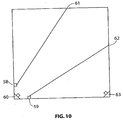
- FIG 10 An alternative is shown in figure 10 , where the lasers 58 and 59 are aimed away from the camera 60.
- the camera 60 can detect a light from the laser light hitting the wall at point 61 and 62. If either of these points disappears, then the detector system knows that either a laser is faulty or something is blocking the path of the laser light. If the laser is blocked, generally the object blocking the laser light will also reflect the light, and therefore the laser spot will shift from the known target area, that is original point 61 or 62.
- the camera can detect the shift in the spot and may sound an alarm or turn the laser off. This may be important, especially if the laser is not considered eye safe.
- Another means by which faults may be detected is when a spurious object such as a spider web intersects with a beam causing scattering. Occasional movement of the emitted beam, for example by translating the emitter in a lateral direction, will obviate such false detections of scattered radiation.
- a second camera 63 is shown which may be connected to the system to provide additional views.
- the additional view will provide scattering information for different scattering angles for the same particulate material. This data can be used to discriminate between materials with different particle size distributions or scattering properties. This in turn can be used to reduce the system sensitivity to nuisance particles that might otherwise cause false alarms such as dust, for example.
- variation in scattering angle; wavelength of emitted radiation; polarisation rotation; plane of polarisation of viewed scattering and varying the timing of emission and detection all provide means for discriminating between different types of particles.
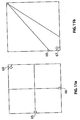
- a camera 64 views two lasers 65 and 66 that cross the room.
- Figure 11b uses a laser that is reflected back towards the camera 67, to provide better room coverage and capture both forward and backward scattered light.
- the processor 10 comprises a personal computer running a Pentium 4 chip, Windows 2000 operating system.
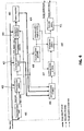
- FIG 4 is a data flow diagram, the layout of which, would be understood by the person skilled in the art.
- the signal processing in this embodiment is conducted using software for the detector 10, referred to as LVSD software.
- the data flow lines indicate image data flow, array data flow and simple numeric or structured data flow at different stages of the processing.
- some of the processing functions described may handle the more intensive image data or optionally, the less intensive numeric data, for example.
- engineering efficiencies may be attained by choice of the components and software entities used to carry out the processing functions at these respective stages.
- a determination of the laser state is performed.
- the LVSD software in this embodiment relies on having the laser source within the field of view of the camera in order to determine the state of the laser for a particular frame.
- a small region of interest is assigned that includes the laser source radiation.
- the centre of the region is set to an initial position of the laser source spot.
- the average pixel value in the region is computed. It is then compared with a threshold value to make the decision of whether the image records the laser on or off.
- the threshold value is the average of the outputs of a peak detector and a trough detector that are fed by the average. Each detector executes an exponential decay back to the current average in the case that a new peak or trough has not been made.
- the time constant is set in terms of frames, preferably with values of about 10.
- An alternative method is to look for one or more pixels that exceeded the average in the rectangle by a fixed threshold.
- this function may not be required. However, it can still serve a double check that the laser source is not obscured and is of the correct intensity.
- a centre of gravity algorithm estimates the pixel co-ordinates of the laser source within the area being monitored. This positional information is optionally updated at every "laser on" image to allow for drift in either the laser source or camera location due to movement of the mounts and/or building over time.
- the factors affecting the stability comprise movement of walls within the building, mounting point rigidity etc.
- the threshold established in the previous step is subtracted from the image and negatives are clipped to zero.
- the centre of gravity of the same rectangle used in the state determination then yields (x,y) co-ordinates of the laser spot.
- the pixel values are treated as weight.
- An alternative technique is to treat the previously described area as an image and calculate an average of a large number ( ⁇ 50) of known "emitter off state” images, then subtract the average from the latest image that is known to have been captured with the emitter on.
- the previously described centre of gravity algorithm is then applied to the image data to estimate the position of the spot.
- regions of interest are calculated.
- background cancellation is performed. A combination of interpolation and frame subtraction is used during background cancellation to reduce interfering temporally variant and invariant information from the image.
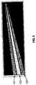
- the image is segmented into three regions of interest as shown in figure 5 .
- the background is segmented into background regions 101 and 103, and there is an integration region 102. These regions are updated periodically to reflect any detected changes in the laser source location.
- the choice of shape of the regions of interest reflects the uncertainty in the precise position in the image of the scattered radiation. In figure 5 the camera cannot see the point where the emitted radiation hits the wall, and therefore the exact path of the emitted radiation is unknown.
- a method of determining the path of the emitted radiation manually is to test the location of the emitted radiation by blocking the radiation temporarily and checking its position, then entering the data manually into the processor.
- one or more substantially transparent probes which may be in the form of articles such as plates, may be inserted into the beam. Some scattering will occur on entry and exit from the plate providing a reference point or points in the image from which the required integration area and background areas may be computed.
- the windows of such enclosures may act as the substantially transparent plates and, these therefore may establish the path of the beam without the need to intrude into the environments to install the detector system components.
- the purpose of a narrow integration area is to reduce the noise contributions from pixels that are not contributing a scattering signal and also to allow the background regions to be closer to the integration region thus allowing a better estimate of the correction factor that is used for correcting the illumination level in the laser off images.
- the integration region 102 contains the emitted radiation path, while the areas to each side, background region 101 and 103, are used during background cancellation.
- the regions are generally triangular, that is wider further away from the laser source. This is necessary because while the exact location of the radiation spot is known, the exact angle of the path is not, so a greater tolerance is needed at the other end of the path when the camera cannot see where the radiation terminates. There is more noise in a fatter section of integration region due to more pixels, inevitably, each pixel represents a shorter length of the path, so the larger number of samples per unit length allows more averaging. If the camera can see the radiation termination point, there would be less uncertainty of its position and the regions of interest would not need to diverge as much as shown in figure 5 .
- Two background regions 101, 103 are chosen for interpolation of the brightness compensation factor for correcting temporal variations in background lighting on either side of the radiation path in the laser off images. For example, changes in lighting due to two different, independent temporally varying light sources on either side of the radiation path. This principle could be further extended to allow for variations along the path, not just to either side of the path by subdividing the three areas 101, 102, 103 into segments along the length of the radiation path and performing the calculations for each subdivision.
- the background cancelling algorithm sums n "on frames” and m “off frames” - the sequence of these frames is arbitrary. Prior to the subtraction of the “emitter off” frames from the “emitter on” frames, the “emitter off” frames are scaled by a factor, f , to compensate for variance in lumination levels of the images. This may be useful with artificial lighting, the intensity of which varies rapidly.
- the resultant image contains any differences between the n "emitter on” and m “emitter off” images. This is shown graphically in figure 6 .
- a lock step synchronisation technique could be used so that the computer was fed information about the state of the laser with respect to the captured image.
- a minimum of one on frame and one off frame is required for the technique to work.
- An alternative to the cancellation scheme described above is to simply subtract laser on and laser off frames. Many on frames and off frames can be summed or averaged or low pass filtered, with the summing, averaging or filtering performed before and/or after the subtraction.
- the result of the background cancellation is an image that is predominantly composed of scattered light from the emitter, and some residual background light and noise.
- step 405 of figure 4 frame integration is performed.
- a number of background cancelled frames are summed, averaged or otherwise low pass filtered to obtain a scattered light image with reduced noise.
- interference that is not correlated with the laser on / off switching is reduced and the wanted (correlated) scattering information is retained.
- the total number of frames used in the background cancellation and frame integration steps is approximately 100 (i.e. approximately 3 seconds of video). Longer periods of integration or lower filter cut-off frequencies may yield an improved signal to noise ratio, and allow a higher sensitivity system at the expense of response time.
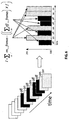
- the sequence of images shows the effect of background cancellation and integration in the detection of the scattered light.
- the image intensity has been scaled to allow for better visibility to the eye.
- the particle obscuration level over the entire beam was approximately 0.15% per metre as measured by a VESDA TM LaserPLUS TM detector, sold by the applicant.
- Figure 7a shows the raw video
- figure 7b highlights the region of integration
- figure 7c the scattered light in the presence of smoke after background cancellation and integration.
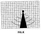
- step 406 of figure 4 computation of the scatter as a function of the radius from the emitter is performed. Variations in intensity along the beam due to system geometry and scattering may be remedied using this method.
- a data array is calculated containing scattered light levels in the integration region versus radius, for example measured in pixels in the captured image; from the laser source. Since a radius arc covers a number of pixels inside the integration, the intensity of each pixel within a given radius interval is summed together.
- Figure 8 is a graphical representation of how the integration region is segmented by arcs centred with respect to the emitter. In figure 8 , triangle 80 represents the expected integration area and the arcs represent different radii from the laser source.
- Each portion of the integration area lying between a pair of arcs has its pixels summed and the sum is entered into the scattered light data array. For pixels that are not clearly between two of the arcs, rounding or truncation of the calculated radius corresponding to such pixels can be used to resolve the ambiguity.
- each pixel as described above corresponds to a specific geometric configuration with respect to a scattering volume and the general case of such an image point is shown in figure 12 .
- the following parameters can therefore be determined:
- a corrected intensity of pixels corresponding to a given radius, r is then determined for a real world system, in which the intensity of pixels is multiplied by a predetermined scattering gain value, discussed below under Scattering Angle Correction, corresponding to the given radius and a given scattering angle relative to a lossless isotropic scattering calculation.
- a resultant scattered data array is formed.
- a correction for scatter angle is logically determined in accordance with step 409 of figure 4 .
- the program requires a scattering data file, which contains for a given material, the scattering angle and its corresponding gain.
- the data in this file is generated by an empirical calibration process, and is intended to contain average values for a variety of smoke types.
- the gain for every scattering angle is derived.
- the data from the input scattering data file is linearly interpolated so that for every scattering angle an approximation of the forward gain can be calculated.
- a determination of smoke for a given radius of the beam is performed at step 407 of figure 4 .
- To convert the scattered data array to smoke levels on a per pixel basis requires input of data D, d and ⁇ i , as shown in figure 12 . Any combination of lengths or angles that constrain the geometry can also be used.
- D is the distance from the camera 82 to the emitter 84
- ⁇ i is the angle made between the line from camera 82 and the emitter 84 and the line corresponding to the path of the radiation from the emitter 84
- d is the length of the line perpendicular to the emitted radiation that intersects the camera entrance pupil. From this information, all other necessary information can be determined by trigonometry and geometry. The geometry can be seen in figure 12 .
- L is the length of the beam that is visible to one camera pixel.
- step 410 of figure 4 integration over beam image sectors is performed to obtain the detected obscuration.
- the beam length is divided into a number of sectors to provide addressability along the beam.
- the pixels around the laser spot location cannot be included as part of a sector, as the intensity caused by scattering cannot be resolved, especially for an uncollimated source for which flaring may occur causing residual intensity in the pixels surrounding the source.
- the field of view of the camera allows the beam to be viewed to within a few meters of the camera.
- a simple moving average filter is implemented.
- the beam is divided into n+1 segments, and then a moving average is applied (of length two segments) resulting in n sectors.
- Each pixel along the beam captured image corresponds to a physical length along the beam see figures 8 and 12 . This physical length gets smaller as the beam approaches the camera. So starting at the laser end and ignoring the pixels that are outside the end boundaries, the obscuration for a particular sector is the sum of all the pixel intensities after the application of the correction noted above, which fall into the physical length and position as described by that sector.
- the beam length is divided into a number of segments to determine individual smoke levels for each segment effectively simulating a number of point detectors.
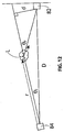
- the output of these notional point detectors can be provided to an addressable fire panel. This is based on the theory that scattered light emitted from each segment of the emitted radiation will provide a different light output for a given particle density based upon the angle from the radiation path to the camera and the number of pixels per segment. As the path of the emitted radiation comes closer to the camera that is as r increases in figure 12 the angle ⁇ r increases. The number of pixels that contain scattered light will also increase due to the apparent widening of the beam in the direction towards the camera 82. This increase in width is shown in figure 8 and figure 13.
- Figure 13 shows the emitted radiation from emitter 84.
- the angle of the radiation spread is amplified for clarity.
- the number of pixels that coincide with the location of potential scattered radiation increases.
- the light from these pixels is summed and placed into an array 90, being scattered_light(r), which comprises a n times 1 array of information, where n is the number of pixels across the screen.
- scattered_light(r) which comprises a n times 1 array of information, where n is the number of pixels across the screen.
- n is the number of pixels across the screen.
- Array 94 contains the actual radius of the light captured by the pixels.
- Array 96 comprises the length of the segment of the emitted radiation encompassed by, in this case, one horizontal pixel in the captured image in the frame of the camera. This information is used to ascertain the volume of the emitted radiation and is used to assist in the calculation of the radiation intensity. Also, array 96 contains data on the smoke intensity at each point r, defined as smoke [r].
- alarm states are calculated.
- the alarm states for each sector are determined based on thresholds and delays and a priority encoding scheme, as per standard aspirated smoke detectors, or other parameters determined by the user.
- the system may have provision for the detection of a fault condition, which is essentially the absence of the laser spot in the image.
- the laser on/off signal duty cycle may be checked to be within 33% to 66% over the number of frames used in one background cancellation cycle.
- the system described above could be used in applications where measurement of obscuration was important, such as airports where fog may cause planes to divert if visibility falls below a certain level.
- the system does not require ambient light to operate, and can therefore operate at night without additional lighting.
- An infrared camera could also be used with an infrared light source, where the light source, if of similar frequency to the detecting light, could be cycled so that the processor ignores frames illuminated for security purposes.
- a typical security camera may take 25 images or frames per second. Smoke detection may only require detecting 1 frame per second or less. Therefore the remaining images can be used for security purposes.
- video processing software operating within the detection sub-system (6,7) may be used to eliminate the contribution of nuisance changes in video signals which are not in the location known to be occupied by the light beam.
- Software based systems which perform a similar function of processing distinct areas of a video image are known, for example in video-based security systems such as Vision System's ADPRO TM products.
- the emitter may be a laser, emitting polarised radiation.
- the laser may emit visible radiation, infrared radiation or ultra violet radiation. Selection of the wavelength of the radiation may be dependent on the characteristics of the particles to be detected, as well as the characteristics of the apparatus and method to be employed in the detection of the particles.
- Other types of radiation emitter may comprise a xenon flash tube, other gas discharge tubes, or a laser diode or light emitting diode.
- the light is preferably collimated to at least some degree, but if the optional area segregation using regions of interest is employed, a broader radiation beam may be emitted.
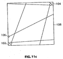
- FIG. 11c A further embodiment is shown in Figure 11c , which employs two cameras 102 and 104, and a single laser 106.
- one camera can view the emitter, and the other the position or target where the radiation hits the wall 108.
- the cameras 102, 104 are connected to the same processor or at least communicate with each other.
- This system provides many advantages, such as confirmation that the radiation is not blocked, and can be used to determine more accurately a position of the emitter radiation with respect to camera 104, which detects the forward scatter of light. As such, the degree of uncertainty of the position of the path of the emitted radiation is reduced, and the regions of interest can be reduced in size, increasing the sensitivity of the detector system.
Description
- The present invention relates to an improved sensor apparatus and improved method of sensing. In particular the present invention relates to an improved particle detector and method of detecting particles.
- There are a number of ways of detecting smoke in a region, such as a room, building, enclosure, or open space. Some methods involve sampling air from the region and passing the sampled air through a detection chamber, whereby particles are detected and an estimation is made of the amount of smoke in the region of interest. Such an apparatus is exemplified in aspirated smoke detectors like LaserPLUS™ sold by the applicant.
- Other detectors are placed in the region of interest, and use a sensor to detect particles adjacent the sensor. An example of such a detector is a point detector, in which air passes between an emitter and a sensor, and the smoke is detected directly in the region of interest.
- In both cases if the smoke does not enter a sampling point (of the aspirated detector) or pass between the sensor and emitter of the point detector, no smoke will be detected. As many buildings employ air handling means for extracting air from a region, such as air-conditioning, there is no guarantee that smoke will be detected rather than pass out of the region via the air handling ducts. It can be very difficult to use the aforementioned methods of detecting smoke in outdoor areas or very large indoor arenas where there may not be appropriate locations to place a point detector or a sample point and connecting tubing.
- Other devices used to detect smoke include the detector disclosed in
US 3,924,252, (Duston ) which uses a laser and a photodiode to detect light scattered from particles. This device uses a corner reflector to reflect the light back at the emitter. Duston requires a feedback circuit to detect whether the beam is emitted or blocked. - Another type of detector is known as a "Beam Detector", which measures the attenuation of the intensity of a signal from a projected light source caused by smoke particles suspended in the projected light. These detectors have relatively low sensitivity and are only capable of measuring the total attenuation within the illuminated region.
-
JP 10 154 284 -
JP 11 339 150 - Any discussion of documents, devices, acts or knowledge in this specification is included to explain the context of the invention. It should not be taken as an admission that any of the material forms a part of the prior art base or the common general knowledge in the relevant art in Australia or elsewhere on or before the priority date of the disclosure and claims herein.
- According to the present invention there is provided a method of detecting particles according to the appended claims.
- With respect to the above method, further steps embodying the method and features of preferred embodiments may include identifying an area of interest in the images which represents a corresponding zone of the monitored region. Scattered radiation within the zone may be represented in one or more segments of a corresponding image, which allows for the location of the particles in the region to be identified. The location of the particles may be determined in accordance with a geometric relationship between the locations of a source of emitted radiation, a direction of the emitted radiation and a point of image detection wherein, the geometric relationship is determined from the images. The detected variation may be an increase in scattered radiation intensity. The increase in scattered radiation intensity may be assessed with reference to a threshold value. The threshold value may be calculated by averaging integrated intensity values from the images. The method may comprise assigning different threshold values for different spatial positions within the region. The method may comprise directing the radiation along a path and identifying a target in the images, the target representing a position at which the radiation is incident on an objective surface within the region. A location of the target in the images may be monitored and the emission of radiation may be ceased in response to a change in the location of the target. The method comprise identifying a location of an emitter in the images. Further, the method may comprise determining an operating condition of the emitter based on radiation intensity at the identified location of the emitter. The images may be processed as frames which are divided into sections which represent spatial positions within the monitored region. Also, the method may comprise monitoring intensity levels in associated sections of the images and assigning different threshold values for different spatial positions within the region which correspond to the associated sections.
- In another aspect, there is provided an apparatus according to the appended claims.
- The processor may be adapted to determine the location of particles in accordance with a geometric relationship between the locations of the emitter, the directed beam of radiation and the image capture device wherein, the geometric relationship is determined from the analysed images. The apparatus may comprise a plurality of emitters, arranged to direct radiation along different respective beam paths. The apparatus may further comprise one or more filters for adapting the image capture device to capture radiation from the emitter in preference to radiation from other sources. The filters may be one or more or a combination of:
- a temporal filter.
- a spatial filter.
- a band-pass filter.
- a polarising filter.
- The image capture device preferably comprises an attenuator. The attenuator may comprise a variable aperture device. A plurality of image-capturing devices may be used. Preferably, the image capture device comprises a camera. It is also preferable that the emitter comprises a laser.
- Other aspects, advantages and features are disclosed in the specification and / or defined in the appended claims, forming a part of the description of the invention.
- Further scope of applicability of the present invention will become apparent from the detailed description given hereinafter. However, it should be understood that the detailed description and specific examples, while indicating preferred embodiments of the invention, are given by way of illustration only.
- Further disclosure, improvements, advantages, features and aspects of the present application may be better understood by those skilled in the relevant art by reference to the following description of preferred embodiments taken in conjunction with the accompanying drawings, which are given by way of illustration only, and thus are not limiting to the scope of the present invention, and in which:
-
Figure 1 shows a schematic representation of an embodiment of a detector system from a side view; -
Figure 2 shows a top plan view of an embodiment of an image capture device and emitter position of the detector system offigure 1 ; -
Figure 3 shows a schematic perspective representation of an image taken by an image capture device offigure 2 ; -
Figure 4 shows a system overview workflow for signal processing for the detector system offigure 1 ; -
Figure 5 shows a graphical representation of segmentation of data captured by the image capture device in the embodiment offigure 1 ; -
Figure.6 shows a graphical representation of the integration of the data captured by the image capture device of the embodiment offigure 1 ; -
Figure 7a-c shows images illustrating background cancellation performed by the detection system offigure 1 ; -
Figure 8 shows a graphical representation of a method used for calculating pixel radius in an embodiment of the software used in conjunction with the operation of the detector system offigure 1 ; -
Figure 9 is a top plan schematic view of a second embodiment of a detector system in accordance with the present invention; -
Figure 10 is a top plan schematic view of a third embodiment of a detector system in accordance with the present invention; -
Figures 11a-c are top plan schematic views of fourth, fifth and sixth embodiments of the detector system in accordance with the present invention; -
Figure 12 shows a schematic representation of a part of the detector system offigure 1 ; -
Figure 13 shows a schematic representation of captured image data from an image capture device of the detector system offigure 1 ; - In
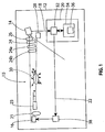
figure 1 , an embodiment of aparticle detector 10 is shown. Thedetector 10 is located in aregion 12 to be monitored. The region could be a room, stadium, hallway, or other area. It is not necessary for the region to be enclosed or indoors. - An
image capture device 14 views at least a portion of theregion 12, comprising a portion that contains electromagnetic radiation fromemitter 16. Theimage capture device 14 may be a camera or one or more devices forming a directionally sensitive electromagnetic receiver such as photodiodes or CCD's, for example. In the preferred embodiment, theimage capture device 14 is a camera. In the present embodiment, thecamera 14 uses full frame capture to capture the images to send analogue video information along communications link 18 to aprocessor 20. It is not necessary to use full frame capture. However, it is preferable to use full frame capture for engineering simplicity in obtaining images, performance, and minimising installation restrictions. As would be understood by the person skilled in the art, otherimage capture devices 14 such as line transfer cameras may be used and methods to compensate for the efficiency of full frame capture may be employed. Anothercommunication link 22 connects theemitter 16 to theprocessor 20. Theprocessor 20 controls the output ofemitter 16, and/or receives information about the output ofemitter 16 through the communications link 22. Alternatively, the state of theemitter 16 may be sensed by thecamera 14 or determined automatically as disclosed below. In the preferred embodiment, theemitter 16 is a laser producing visible, infra-red or other suitable radiation. The laser16 may incorporate a lens 21 and spatial filter such as a field ofview restrictor 23. When a beam of light travels thought a homogeneous medium there is no scattering, only when irregularities are present does the beam scatter. Therefore, in the presence of particles such as smoke particles the laser beam will scatter. Furthermore, in accordance with the preferred embodiment, thelaser 16 may be modulated, eg "laser on", laser "off" in a given sequence. When no smoke is present, the intensity of pixels in a captured image including the laser beam is the same regardless of the state of the laser. When smoke is present, there is a difference between the intensity of a captured image when thelaser 16 is on (due to scattering), compared to the intensity when thelaser 16 is turned off. - Optional filters are shown in
figure 1 in the form of apolarizing filter 24 and aband pass filter 26. The polarisingfilter 24 is adapted to allow electromagnetic radiation emitted from theemitter 16 to pass through, while preventing some of the background light from entering thecamera 14. This is useful if theemitter 16 is a laser emitting polarised light, then the polarisingfilter 24 can be aligned with the polarisation angle of the laser beam to allow maximum transmission of laser light, while removing some background light, which typically is from randomly or non polarised light sources. Thesecond filter 26 is a band pass filter, which attempts to only allow light within a predetermined frequency range (i.e. the frequency of the electromagnetic radiation from the emitter 16). For example, an interference filter or coloured gel may be used as theband pass filter 26. By using a band pass filter (for example allowing substantially only light around 640 nm if a red laser of that frequency is used), significant background light will be removed, increasing the relative intensity of light scattered from particles suspended in the air in theregion 12. - Other filtering methods comprise modulation of the laser and use of positional information with regard to the systems components as described below.
- The image capture device may employ an attenuator for controlling the radiation received. A controllable neutral density filter arrangement may be used. Alternatively, the attenuator could be in the form of controlling the intensity with a variable aperture. An optional, adjustable,
iris 24a can be used to control exposure levels. It can be manually set at the time of installation, or the system could automatically set the exposure according to incident light levels. The reason for this is to minimise or avoid camera saturation, at least in the parts of the field of view that are used in subsequent processing. Theiris 24a could be a mechanical iris or an LCD iris or any other means to reduce the amount of light entering the camera. Some electronic cameras incorporate an electronic shutter, and in this case the shutter time can be used to control exposure instead of aniris 24a. Aspatial filter 24b is also shown, which may for example comprise a slit for effectively masking the incident light to thecamera 14. For example, a slit may mask the incident received light at thecamera 14 to conform generally to the shape of the laser beam as it would be projected in the plane of thecamera 14 lens.Items - In use, electromagnetic radiation, such as a red laser light from
emitter 16, passes through theregion 12 and impacts on a wall or anabsorber 28. The field of view of thecamera 14 comprises at least part of the path of the laser, and optionally, the impact point of the laser on the wall, which in this case impacts on anabsorber 28. Particles in the air in the region that intersect the laser, in this case represented byparticle cloud 30, will cause laser light to scatter. Some of the light scattered from particles will fall on the sensor of thecamera 14, and be detected. - In the embodiment shown in
figure 1 thecamera 14 outputs analogue information to avideo capture card 32 of theprocessor 20. Thevideo capture card 32 converts the analogue information to digital information which is then further processed bycomputer 34. The processing is undertaken bysoftware 36 running on thecomputer 34, which will be described later. In the preferred embodiment, the processing is carried out in order to interpret the captured image(s) such that an image plane corresponds to or is mapped to corresponding positions on the laser beam. This may be achieved by relatively straightforward geometry and trigonometry once predetermined location or position information of the system's components is obtained. - In other embodiments it is possible to use a
camera 14 which would capture the data and transmit it digitally to theprocessor 20 without the need for avideo capture card 32. Further, thecamera 14, filters 24,26,processor 20 andlight source 16 could be integrated into a single unit or units. Also, embedded systems may be employed to provide the functions of at least theprocessor 20. - A number of
camera 14 configurations are able to be used in this application, provided image information in the form of data can be supplied to theprocessor 20. - In the example shown in
figure 1 , alaser modulator 38 is used to vary the power of theemitter 16. The power level can be changed to suit lighting conditions, meet eye safety requirements and provide on/off modulation. In this embodiment, thecamera 14captures 30 frames every second, theemitter 16 is cycled on for one frame and off for the next. The amount of light in a region is sensed for each frame, and the sum of the light in a region when the laser is off is subtracted from the sum of light received while the laser is on. The sums may be over several frames. The difference between the sum of light received when the laser is on compared to the light received when the laser is off is taken as a measure of the amount of scattering in that region. To act as an alarm, a threshold difference is set and should the difference be exceeded, the alarm may be activated. In this way thedetector 10 may act as a particle detector. As measuring the scattered light from particles is known to be a method of determining whether there is smoke in a region, thedetector 10 may be used as a smoke detector. More detail on the cancellation, filtering and software is provided below. - The
detector 10 may be set to wait until the measured scattering exceeds a given threshold for a predetermined period of time, before indicating an alarm or pre-alarm condition. The manner for determining an alarm or pre-alarm condition for thedetector 10 may be similar to the methods used in aspirated smoke detectors using a laser in a chamber, such as the VESDA™ LaserPLUS™ smoke detector sold by Vision Fire and Security Pty Ltd. -
Figure 2 shows a top view of the embodiment infigure 1 . Thecamera 14 has a field of view θ, which in this case covers substantially all theregion 12, which may be a room in a building. The light fromemitter 16 is directed generally towards thecamera 14, but not directly at the lens. There is therefore an angle subtended by an imaginary line between thecamera 14 and theemitter 16, and the direction of the laser beam. The angle may be in the horizontal plane as shown by angle z infigure 2 , and/or the vertical plane as shown by angle x infigure 1 . The laser beam does not impact on the camera lens directly. Nonetheless, the laser beam path will be in the field of view of thecamera 14, as shown infigure 3 . - It is desirable in some circumstances to use a number of emitters in a system. This may be to comply with regulations, provide back up, or to assist in covering a larger area than could be covered with a single emitter.
- If coverage of a large area is required, it is possible to employ a number of emitters so that smoke may be detected in a number of different locations within a region.
Figure 9 shows an arrangement wherebycamera 50 is located within a region such aroom 52. If detection was required across a large area,multiple lasers Figure 9 shows the emitters grouped into two groups, with emitters fromgroup 54 targeted atpoint 56 andemitters 55 targeted atpoint 57. Thecamera 50 may have thepoints points Camera 50 may havepoints points camera 50, for example, rear view mirrors (not shown) placed forward ofcamera 50. Likewise a prism or some other optical system could achieve this result Further, theemitters camera 50 can detect the point at which the radiation lands, the radiation detected in the camera can be used to verify that the emitter is operating and not blocked. Detection of individual emitters is possible if they were switched on and off sequentially, or in any sequence of patterns that are not linearly dependant, so that using timing information, it is possible to detect which emitter is on at any one time. Further, knowing which emitter was firing would allow the detector to localise sub regions in the area to be protected and ascertain where any detected particles were located with respect to the sub regions. In effect the beam or beams that have been scattered by particles may be determined. - The
emitters targets - An alternative is shown in
figure 10 , where thelasers camera 60. Thecamera 60 can detect a light from the laser light hitting the wall atpoint original point - In
figure 10 asecond camera 63 is shown which may be connected to the system to provide additional views. Using two cameras may allow a more accurate means of locating the area of smoke than using a single camera. Also, the additional view will provide scattering information for different scattering angles for the same particulate material. This data can be used to discriminate between materials with different particle size distributions or scattering properties. This in turn can be used to reduce the system sensitivity to nuisance particles that might otherwise cause false alarms such as dust, for example. With the use of one or more emitters, variation in scattering angle; wavelength of emitted radiation; polarisation rotation; plane of polarisation of viewed scattering and varying the timing of emission and detection all provide means for discriminating between different types of particles. - In
figure 11 acamera 64 views twolasers Figure 11b uses a laser that is reflected back towards thecamera 67, to provide better room coverage and capture both forward and backward scattered light. - In the present embodiment, the
processor 10 comprises a personal computer running a Pentium 4 chip, Windows 2000 operating system. - An important aspect of the present embodiments is signal processing is discussed in detail below with reference to
figure 4 which is a data flow diagram, the layout of which, would be understood by the person skilled in the art. For ease of reference, the signal processing in this embodiment is conducted using software for thedetector 10, referred to as LVSD software. It is to be noted with reference tofigure 4 that the data flow lines indicate image data flow, array data flow and simple numeric or structured data flow at different stages of the processing. Thus, some of the processing functions described may handle the more intensive image data or optionally, the less intensive numeric data, for example. As would be understood by the person skilled in the art, engineering efficiencies may be attained by choice of the components and software entities used to carry out the processing functions at these respective stages. - At
step 401 offigure 4 a determination of the laser state is performed. The LVSD software in this embodiment relies on having the laser source within the field of view of the camera in order to determine the state of the laser for a particular frame. - A small region of interest is assigned that includes the laser source radiation. The centre of the region is set to an initial position of the laser source spot. The average pixel value in the region is computed. It is then compared with a threshold value to make the decision of whether the image records the laser on or off.
- The threshold value is the average of the outputs of a peak detector and a trough detector that are fed by the average. Each detector executes an exponential decay back to the current average in the case that a new peak or trough has not been made. The time constant is set in terms of frames, preferably with values of about 10.
- This technique has proven to be fairly robust. An alternative method is to look for one or more pixels that exceeded the average in the rectangle by a fixed threshold.
- In an implementation where the laser on/off switching is more closely coupled to frame acquisition this function may not be required. However, it can still serve a double check that the laser source is not obscured and is of the correct intensity.
- At
step 401 offigure 4 , a centre of gravity algorithm estimates the pixel co-ordinates of the laser source within the area being monitored. This positional information is optionally updated at every "laser on" image to allow for drift in either the laser source or camera location due to movement of the mounts and/or building over time. The factors affecting the stability comprise movement of walls within the building, mounting point rigidity etc. - More precisely, the threshold established in the previous step (laser state determination) is subtracted from the image and negatives are clipped to zero. The centre of gravity of the same rectangle used in the state determination then yields (x,y) co-ordinates of the laser spot. In this calculation, the pixel values are treated as weight.
- An alternative technique is to treat the previously described area as an image and calculate an average of a large number (~50) of known "emitter off state" images, then subtract the average from the latest image that is known to have been captured with the emitter on. The previously described centre of gravity algorithm is then applied to the image data to estimate the position of the spot.
- At
step 403 offigure 4 , regions of interest are calculated. Atstep 404 offigure 4 , background cancellation is performed. A combination of interpolation and frame subtraction is used during background cancellation to reduce interfering temporally variant and invariant information from the image. The image is segmented into three regions of interest as shown infigure 5 . The background is segmented intobackground regions integration region 102. These regions are updated periodically to reflect any detected changes in the laser source location. The choice of shape of the regions of interest reflects the uncertainty in the precise position in the image of the scattered radiation. Infigure 5 the camera cannot see the point where the emitted radiation hits the wall, and therefore the exact path of the emitted radiation is unknown. This produces a region ofinterest 102 that expands as the distance from the emitter increases. A method of determining the path of the emitted radiation manually is to test the location of the emitted radiation by blocking the radiation temporarily and checking its position, then entering the data manually into the processor. Alternatively, one or more substantially transparent probes, which may be in the form of articles such as plates, may be inserted into the beam. Some scattering will occur on entry and exit from the plate providing a reference point or points in the image from which the required integration area and background areas may be computed. In applications where the detector may be used for detecting particles in, for example, clean room or hazardous environments, the windows of such enclosures may act as the substantially transparent plates and, these therefore may establish the path of the beam without the need to intrude into the environments to install the detector system components. The purpose of a narrow integration area is to reduce the noise contributions from pixels that are not contributing a scattering signal and also to allow the background regions to be closer to the integration region thus allowing a better estimate of the correction factor that is used for correcting the illumination level in the laser off images. - The
integration region 102 contains the emitted radiation path, while the areas to each side,background region figure 5 . - Two
background regions areas - The background cancelling algorithm sums n "on frames" and m "off frames" - the sequence of these frames is arbitrary. Prior to the subtraction of the "emitter off" frames from the "emitter on" frames, the "emitter off" frames are scaled by a factor, f, to compensate for variance in lumination levels of the images. This may be useful with artificial lighting, the intensity of which varies rapidly. The resultant image contains any differences between the n "emitter on" and m "emitter off" images. This is shown graphically in
figure 6 . - The scaling factor f is determined by interpolation, using the ratios of background variation between the laser on and laser off frames.

- µ is the average value of pixel intensity in a given background region in either a laser on or laser off frame as designated by the subscripts.
- If the processor is not fast enough to keep up with the full frame rate, there needs to be a scheme to allow a random selection of frames to be processed. Since n laser on and m laser off frames are used for the backgound cancellation, while waiting to accumulate this number of frames, any excess laser on or laser off frames can be discarded.
- Alternatively a lock step synchronisation technique could be used so that the computer was fed information about the state of the laser with respect to the captured image. In any case, a minimum of one on frame and one off frame is required for the technique to work.
- An alternative to the cancellation scheme described above is to simply subtract laser on and laser off frames. Many on frames and off frames can be summed or averaged or low pass filtered, with the summing, averaging or filtering performed before and/or after the subtraction.
- The result of the background cancellation is an image that is predominantly composed of scattered light from the emitter, and some residual background light and noise.
- At
step 405 offigure 4 frame integration is performed. A number of background cancelled frames are summed, averaged or otherwise low pass filtered to obtain a scattered light image with reduced noise. By averaging a number of frames, interference that is not correlated with the laser on / off switching is reduced and the wanted (correlated) scattering information is retained. Typically the total number of frames used in the background cancellation and frame integration steps is approximately 100 (i.e. approximately 3 seconds of video). Longer periods of integration or lower filter cut-off frequencies may yield an improved signal to noise ratio, and allow a higher sensitivity system at the expense of response time. - With reference to
figures 7a to 7c , the sequence of images shows the effect of background cancellation and integration in the detection of the scattered light. The image intensity has been scaled to allow for better visibility to the eye. The particle obscuration level over the entire beam was approximately 0.15% per metre as measured by a VESDA™ LaserPLUS™ detector, sold by the applicant.Figure 7a shows the raw video,figure 7b highlights the region of integration, andfigure 7c the scattered light in the presence of smoke after background cancellation and integration. - At
step 406 offigure 4 computation of the scatter as a function of the radius from the emitter is performed. Variations in intensity along the beam due to system geometry and scattering may be remedied using this method. A data array is calculated containing scattered light levels in the integration region versus radius, for example measured in pixels in the captured image; from the laser source. Since a radius arc covers a number of pixels inside the integration, the intensity of each pixel within a given radius interval is summed together.Figure 8 is a graphical representation of how the integration region is segmented by arcs centred with respect to the emitter. Infigure 8 , triangle 80 represents the expected integration area and the arcs represent different radii from the laser source. Each portion of the integration area lying between a pair of arcs has its pixels summed and the sum is entered into the scattered light data array. For pixels that are not clearly between two of the arcs, rounding or truncation of the calculated radius corresponding to such pixels can be used to resolve the ambiguity. - At
step 408 offigure 4 , the geometry of the system elements/components is determined. Each pixel as described above (or image point) corresponds to a specific geometric configuration with respect to a scattering volume and the general case of such an image point is shown infigure 12 . At each such point or pixel, the following parameters can therefore be determined: - θ - scattering angle.
- r - the distance in meters from the laser source.
- D - distance from camera to laser source.
- L - physical length viewed by one pixel at a given point along the beam.
- A corrected intensity of pixels corresponding to a given radius, r, is then determined for a real world system, in which the intensity of pixels is multiplied by a predetermined scattering gain value, discussed below under Scattering Angle Correction, corresponding to the given radius and a given scattering angle relative to a lossless isotropic scattering calculation. A resultant scattered data array is formed.
- A correction for scatter angle is logically determined in accordance with
step 409 offigure 4 . As an input, the program requires a scattering data file, which contains for a given material, the scattering angle and its corresponding gain. The data in this file is generated by an empirical calibration process, and is intended to contain average values for a variety of smoke types. - At each scattering angle as determined during the above geometry computation, the gain for every scattering angle is derived. The data from the input scattering data file is linearly interpolated so that for every scattering angle an approximation of the forward gain can be calculated.
- A determination of smoke for a given radius of the beam is performed at
step 407 offigure 4 . To convert the scattered data array to smoke levels on a per pixel basis requires input of data D, d and θi, as shown infigure 12 . Any combination of lengths or angles that constrain the geometry can also be used. D is the distance from thecamera 82 to theemitter 84, θi is the angle made between the line fromcamera 82 and theemitter 84 and the line corresponding to the path of the radiation from theemitter 84, and d is the length of the line perpendicular to the emitted radiation that intersects the camera entrance pupil. From this information, all other necessary information can be determined by trigonometry and geometry. The geometry can be seen infigure 12 . - For each element in the previously described Scatter vs Radius Array, the values of L, θr and r, as shown in
figure 12 , are computed. L is the length of the beam that is visible to one camera pixel. - At
step 410 offigure 4 , integration over beam image sectors is performed to obtain the detected obscuration. The beam length is divided into a number of sectors to provide addressability along the beam. In order to distinguish between the laser source and scattering of the laser beam, the pixels around the laser spot location cannot be included as part of a sector, as the intensity caused by scattering cannot be resolved, especially for an uncollimated source for which flaring may occur causing residual intensity in the pixels surrounding the source. - Likewise at the camera end, due to the geometry of the set up, the field of view of the camera allows the beam to be viewed to within a few meters of the camera.
- In order to provide a smooth transition between sector boundaries, a simple moving average filter is implemented. In fact, the beam is divided into n+1 segments, and then a moving average is applied (of length two segments) resulting in n sectors.
- Each pixel along the beam captured image corresponds to a physical length along the beam see
figures 8 and12 . This physical length gets smaller as the beam approaches the camera. So starting at the laser end and ignoring the pixels that are outside the end boundaries, the obscuration for a particular sector is the sum of all the pixel intensities after the application of the correction noted above, which fall into the physical length and position as described by that sector. - For example, to determine the obscuration, O, over the whole beam, given as a sector size in pixel radius, r, as n to m,

- As noted above, the beam length is divided into a number of segments to determine individual smoke levels for each segment effectively simulating a number of point detectors. The output of these notional point detectors can be provided to an addressable fire panel. This is based on the theory that scattered light emitted from each segment of the emitted radiation will provide a different light output for a given particle density based upon the angle from the radiation path to the camera and the number of pixels per segment. As the path of the emitted radiation comes closer to the camera that is as r increases in
figure 12 the angle θr increases. The number of pixels that contain scattered light will also increase due to the apparent widening of the beam in the direction towards thecamera 82. This increase in width is shown infigure 8 andfigure 13. Figure 13 shows the emitted radiation fromemitter 84. The angle of the radiation spread is amplified for clarity. As the emitted radiation travels further from the emitter (that is as r increases), the number of pixels that coincide with the location of potential scattered radiation increases. At theradius 86, close to the emitter, only two pixels are determined to be within the region of interest covered by the detector, and the light from these pixels is summed and placed into anarray 90, being scattered_light(r), which comprises a ntimes 1 array of information, where n is the number of pixels across the screen. Atradius 88, many more pixels are within the area of interest covered by the detector, and they are all summed to obtain the amount of scattering obtained within the covered region of interest. Calculated atarray 92 is the scattering radiation angle θr, which will be different for each pixel. That is, when r is small, θr will be small, and as r increases, so does θr. This information is important, as particles of interest in detecting certain events can have different scattering characteristics. Very small particles (relative to the wavelength of the emitted radiation) scatter more uniformly regardless of θr (scattering angle), however larger particles scatter more in the forward direction, and reduce intensity as the angle θr increases. Quite often the particles of interest, in this example smoke particles, are relatively large particles and therefore it can be useful to employ a table of effective scaling factors of output of light for given scattering angles θr. Such tables are known in the use of smoke detectors using laser chambers to detect particles. -
Array 94 contains the actual radius of the light captured by the pixels.Array 96 comprises the length of the segment of the emitted radiation encompassed by, in this case, one horizontal pixel in the captured image in the frame of the camera. This information is used to ascertain the volume of the emitted radiation and is used to assist in the calculation of the radiation intensity. Also,array 96 contains data on the smoke intensity at each point r, defined as smoke [r]. - Finally with reference to
figure 4 , alarm states are calculated. The alarm states for each sector are determined based on thresholds and delays and a priority encoding scheme, as per standard aspirated smoke detectors, or other parameters determined by the user. - The same method is used for the zone alarm level, except that final zone output is the highest sector or the zone level, whichever is higher.
- The system may have provision for the detection of a fault condition, which is essentially the absence of the laser spot in the image. The laser on/off signal duty cycle may be checked to be within 33% to 66% over the number of frames used in one background cancellation cycle.
- A number of alternative embodiments are available, depending on application and desired features. Unless otherwise specified, the general principles of operation as described above apply to the implementation of the following variations. For example, fault detection may be carried out in a number of ways.
- In another application, the system described above could be used in applications where measurement of obscuration was important, such as airports where fog may cause planes to divert if visibility falls below a certain level. The system does not require ambient light to operate, and can therefore operate at night without additional lighting. An infrared camera could also be used with an infrared light source, where the light source, if of similar frequency to the detecting light, could be cycled so that the processor ignores frames illuminated for security purposes.
- A typical security camera may take 25 images or frames per second. Smoke detection may only require detecting 1 frame per second or less. Therefore the remaining images can be used for security purposes.
- To give increased sensitivity, video processing software operating within the detection sub-system (6,7) may be used to eliminate the contribution of nuisance changes in video signals which are not in the location known to be occupied by the light beam. Software based systems which perform a similar function of processing distinct areas of a video image are known, for example in video-based security systems such as Vision System's ADPRO™ products.
- The emitter may be a laser, emitting polarised radiation. The laser may emit visible radiation, infrared radiation or ultra violet radiation. Selection of the wavelength of the radiation may be dependent on the characteristics of the particles to be detected, as well as the characteristics of the apparatus and method to be employed in the detection of the particles. Other types of radiation emitter may comprise a xenon flash tube, other gas discharge tubes, or a laser diode or light emitting diode. The light is preferably collimated to at least some degree, but if the optional area segregation using regions of interest is employed, a broader radiation beam may be emitted.
- A further embodiment is shown in
Figure 11c , which employs twocameras single laser 106. In this embodiment, one camera can view the emitter, and the other the position or target where the radiation hits thewall 108. In such a configuration, it is desirable if thecameras camera 104, which detects the forward scatter of light. As such, the degree of uncertainty of the position of the path of the emitted radiation is reduced, and the regions of interest can be reduced in size, increasing the sensitivity of the detector system. Further, as it is known that large particles, commonly caused by fire, forward scatter more than smaller particles (often associated with dust), a determination of particle characteristics can be made. If there is significantly more forward scatter than back scatter for a particular segment of the emitted radiation path, then it may be interpreted that the particle density at that particular segment consists of a proportion of large particles. It may be useful to compare this to other segments or other times, in order to ascertain characteristics of the event that caused the particles to be present in the first place. - While this invention has been described in connection with specific embodiments thereof, it will be understood that it is capable of further modification(s). This application is intended to cover any variations uses or adaptations of the invention following in general, the principles of the invention and comprising such departures from the present disclosure as come within known or customary practice within the art to which the invention pertains and as may be applied to the essential features hereinbefore set forth.
- "Comprises/comprising" when used in this specification is taken to specify the presence of stated features, integers, steps or components but does not preclude the presence or addition of one or more other features, integers, steps, components or groups thereof.
Claims (15)
- A method of configuring a smoke detector for detecting smoke by radiation scattering at one or more subregions in a region of interest comprising:directing a beam of radiation within the region, selecting a view of at least a portion of a path of the beam with an image capture device (82),determining the location of the source (84) of the radiation relative to the image capture device,determining the direction of the beam relative to the image capture device (82),dividing the beam of radiation into segments, determining a geometric relationship between the segments and the image capture device (82), andcorrecting the intensity of light received by the image capture device (82) for each segment depending on the geometric relationship.
- A method as claimed in claim 1, wherein the segments comprise at least one pixel.
- A method as claimed in any one of the preceding claims wherein the step of correcting the intensity of light received by the image capture device (82) for each segment includes multiplying the intensity of the pixels by a predetermined scattering gain value, said value corresponding to the distance (r) from the light source (84) and the scattering angle (θr) of the scattering volume to which the pixels correspond.
- A method as claimed in any one of the preceding claims, wherein the segments are grouped to form the subregions for smoke detection.
- A method as claimed in claims 3 or 4 which further
includes:dividing the beam length in a number of sectors,in each a sector, summing all the pixel intensities, after they have been multiplied by said predetermined scattering gain values, which fall into the physical length and position corresponding to said sector. - A method as claimed in claim 3 or 4 wherein obscuration, O, over the whole beam, is determined according to the following equation:
 wherein r is the distance from the source (84) of the radiation of the scattering volume to which each pixel correspond,where S(r) is the scattered light intensity received ; andL(r) is length of the emitted beam viewed by one pixel at a distance r from the source of radiation.
 - A method as claimed in any one of the preceding claims wherein determining the location of the source of the radiation relative to the image capture device includes using a centre of gravity algorithm to estimate the pixel coordinate of the source of radiation.
- A method as claimed in any one of the preceding claims wherein selecting a view of at least a portion of a path of the beam with an image capture device (82) includes determining an integration region that contains the emitted radiation path.
- A method as claimed in any one of the preceding claims which further includes:performing background cancellation of the images of the selected a view of the beam.
- A method as claimed in claim 9 wherein the beam of radiation is modulated, and background cancelation includes summing n "on" frames and m "off" frames.
- A method as claimed in any one of the preceding claims which further includes low-pass filtering a plurality of frames to remove interference that is not correlated with the laser on/off modulation and retain light scattering information.
- A method for detecting smoke by radiation scattering wherein the method includes a method as claimed in any one of the preceding claims wherein the method includes, determining an individual smoke level for each segment to simulate a number of point detectors.
- A method as claimed in claim 12 wherein the method includes, outputting a smoke level of the simulated point detectors to an addressable fire panel.
- A method for detecting smoke by radiation scattering wherein the method includes a method as claimed in any one of claims 1 to 13, wherein the method
includes indicating an alarm or pre-alarm condition after the measured scattering exceeds a given threshold. - Apparatus for monitoring a region, comprising:an emitter (84) for directing a beam of radiation comprising at least one predetermined characteristic into the region;an image capture device (82) arranged to capture a plurality of images of the monitored region;a processor adapted to analyse the plurality of images according to a method of any one of claims 1 to 14.
Applications Claiming Priority (2)
| Application Number | Priority Date | Filing Date | Title |
|---|---|---|---|
| AU2003902319A AU2003902319A0 (en) | 2003-05-14 | 2003-05-14 | Laser video detector |
| EP04732884.4A EP1627367B1 (en) | 2003-05-14 | 2004-05-14 | Particle detector |
Related Parent Applications (3)
| Application Number | Title | Priority Date | Filing Date |
|---|---|---|---|
| EP04732884.4 Division | 2004-05-14 | ||
| EP04732884.4A Division-Into EP1627367B1 (en) | 2003-05-14 | 2004-05-14 | Particle detector |
| EP04732884.4A Division EP1627367B1 (en) | 2003-05-14 | 2004-05-14 | Particle detector |
Publications (2)
| Publication Number | Publication Date |
|---|---|
| EP2562734A1 EP2562734A1 (en) | 2013-02-27 |
| EP2562734B1 true EP2562734B1 (en) | 2016-07-20 |
Family
ID=31501188
Family Applications (4)
| Application Number | Title | Priority Date | Filing Date |
|---|---|---|---|
| EP12182833.9A Not-in-force EP2562733B1 (en) | 2003-05-14 | 2004-05-14 | Particle detector |
| EP04732884.4A Not-in-force EP1627367B1 (en) | 2003-05-14 | 2004-05-14 | Particle detector |
| EP12182834.7A Not-in-force EP2562734B1 (en) | 2003-05-14 | 2004-05-14 | Particle detector |
| EP12182832.1A Not-in-force EP2562732B1 (en) | 2003-05-14 | 2004-05-14 | Particle detector |
Family Applications Before (2)
| Application Number | Title | Priority Date | Filing Date |
|---|---|---|---|
| EP12182833.9A Not-in-force EP2562733B1 (en) | 2003-05-14 | 2004-05-14 | Particle detector |
| EP04732884.4A Not-in-force EP1627367B1 (en) | 2003-05-14 | 2004-05-14 | Particle detector |
Family Applications After (1)
| Application Number | Title | Priority Date | Filing Date |
|---|---|---|---|
| EP12182832.1A Not-in-force EP2562732B1 (en) | 2003-05-14 | 2004-05-14 | Particle detector |
Country Status (8)
| Country | Link |
|---|---|
| US (6) | US7983445B2 (en) |
| EP (4) | EP2562733B1 (en) |
| JP (4) | JP4750705B2 (en) |
| CN (4) | CN102608593B (en) |
| AU (3) | AU2003902319A0 (en) |
| CA (3) | CA2858059C (en) |
| HK (3) | HK1172953A1 (en) |
| WO (1) | WO2004102498A1 (en) |
Families Citing this family (50)
| Publication number | Priority date | Publication date | Assignee | Title |
|---|---|---|---|---|
| AU2003902319A0 (en) | 2003-05-14 | 2003-05-29 | Garrett Thermal Systems Limited | Laser video detector |
| CN102539384B (en) * | 2004-11-12 | 2016-08-03 | 爱克斯崔里斯科技有限公司 | Particle detector, System and method for |
| US7495573B2 (en) | 2005-02-18 | 2009-02-24 | Honeywell International Inc. | Camera vision fire detector and system |
| DE102006006418A1 (en) * | 2006-02-13 | 2007-08-23 | Gunda Electronic Gmbh | Smoke detection device |
| US7769204B2 (en) * | 2006-02-13 | 2010-08-03 | George Privalov | Smoke detection method and apparatus |
| JP5046552B2 (en) * | 2006-05-17 | 2012-10-10 | パナソニック株式会社 | Photoelectric smoke detector |
| JP4925311B2 (en) * | 2007-03-30 | 2012-04-25 | 能美防災株式会社 | smoke detector |
| US8085157B2 (en) * | 2007-10-24 | 2011-12-27 | Honeywell International Inc. | Smoke detectors |
| CN101952709B (en) | 2007-11-15 | 2015-06-24 | 爱克斯崔里斯科技有限公司 | Particle detection |
| CN105445234B (en) * | 2008-06-10 | 2019-07-16 | 爱克斯崔里斯科技有限公司 | Detection of particles |
| IT1392070B1 (en) * | 2008-11-27 | 2012-02-09 | Müller | METHOD AND SYSTEM FOR REPORTING WAYS OF ESCAPE IN A CLOSED ENVIRONMENT, PARTICULARLY IN A GALLERY |
| US8797531B2 (en) | 2009-05-01 | 2014-08-05 | Xtralis Technologies Ltd | Particle detectors |
| US20110063447A1 (en) * | 2009-09-15 | 2011-03-17 | Uchicago Argonne, Llc | Video-imaging system for radiation threat tracking in real-time |
| GB201003704D0 (en) * | 2010-03-05 | 2010-04-21 | Pcme Ltd | Apparatus and method for monitoring particles in a stack |
| EP2589025A2 (en) * | 2010-07-01 | 2013-05-08 | Thomson Licensing | Method of estimating diffusion of light |
| GB2513366B (en) * | 2013-04-24 | 2015-04-01 | Fire Fighting Entpr Ltd | Improvements in or relating to optical beam detectors |
| CN105324802B (en) * | 2013-06-03 | 2019-05-31 | 爱克斯崔里斯科技有限公司 | Particle detection system and correlation technique |
| US10041673B2 (en) * | 2013-07-25 | 2018-08-07 | Honeywell International Inc. | Flare stack monitoring |
| JP6231333B2 (en) * | 2013-09-05 | 2017-11-15 | ホーチキ株式会社 | Fire detection device and fire detection method |
| US9915732B2 (en) | 2014-02-18 | 2018-03-13 | Onvector Technology Llc | Object detection systems |
| WO2015126855A1 (en) * | 2014-02-18 | 2015-08-27 | Onvector Technology Llc | Object detection systems |
| US10585192B2 (en) | 2014-02-18 | 2020-03-10 | Onvector Technology Llc | Object detection systems |
| US9989967B2 (en) * | 2014-03-04 | 2018-06-05 | Cybernet Systems Corporation | All weather autonomously driven vehicles |
| WO2015134139A1 (en) * | 2014-03-06 | 2015-09-11 | Life Technologies Corporation | Systems and methods for diagnosing a fluidics system and determining data processing settings for a flow cytometer |
| JP6294130B2 (en) * | 2014-04-04 | 2018-03-14 | 株式会社荏原製作所 | Inspection device |
| EP3146517A1 (en) | 2014-05-22 | 2017-03-29 | Carrier Corporation | Wide-area chamberless point smoke detector |
| US9677986B1 (en) * | 2014-09-24 | 2017-06-13 | Amazon Technologies, Inc. | Airborne particle detection with user device |
| US10067234B2 (en) | 2015-02-17 | 2018-09-04 | Honeywell International Inc. | Projected beam detector with imaging device |
| KR101790681B1 (en) * | 2016-04-12 | 2017-11-20 | 아주대학교산학협력단 | Air Cleaner |
| WO2018011232A1 (en) * | 2016-07-11 | 2018-01-18 | Autronica Fire & Security As | Smoke detector dynamic range adjustment system and method |
| CA3032865A1 (en) | 2016-08-04 | 2018-02-08 | Carrier Corporation | Smoke detector |
| US10545222B2 (en) * | 2017-05-08 | 2020-01-28 | Velodyne Lidar, Inc. | LIDAR data acquisition and control |
| CN107144507A (en) * | 2017-07-10 | 2017-09-08 | 西石(厦门)科技有限公司 | One kind can self-alignment double light path dust concentration tester |
| JP2019052854A (en) * | 2017-09-12 | 2019-04-04 | 株式会社東芝 | Radiation detection apparatus and radiation detection method |
| CN107966392A (en) * | 2017-11-28 | 2018-04-27 | 苏州佑克骨传导科技有限公司 | A kind of PM2.5 detects broadcast device |
| CN108593510B (en) * | 2018-05-08 | 2024-03-01 | 南京江宁分析仪器有限公司 | Smoke concentration detection test device and test method thereof |
| WO2019217579A1 (en) | 2018-05-09 | 2019-11-14 | Carrier Corporation | Smoke chamber for multiwave multiangle smoke detector |
| WO2019217504A1 (en) * | 2018-05-11 | 2019-11-14 | Carrier Corporation | Multi-point detection system |
| US10444331B1 (en) * | 2018-06-19 | 2019-10-15 | Namuga Co., Ltd | 3D camera system and method for detecting abnormal state of beam projector module for eye protection |
| US11119212B2 (en) * | 2018-08-10 | 2021-09-14 | Aurora Flight Sciences Corporation | System and method to reduce DVE effect on lidar return |
| CN110694184A (en) * | 2019-10-14 | 2020-01-17 | 深圳大学 | Laser power density adjusting method and device and storage medium |
| WO2021113192A1 (en) * | 2019-12-03 | 2021-06-10 | Purdue Research Foundation | Method and apparatus for sensing suspended dust concentration |
| CN211857087U (en) * | 2020-02-24 | 2020-11-03 | 宁波激智科技股份有限公司 | Interference reducing collimation film |
| CN111736162B (en) * | 2020-08-04 | 2020-11-10 | 中国人民解放军国防科技大学 | Laser illumination echo detection device and method for complex target |
| CN113470300B (en) * | 2021-07-06 | 2022-12-20 | 无锡商业职业技术学院 | Photoelectric control system for high-precision smoke detector |
| WO2023281824A1 (en) * | 2021-07-06 | 2023-01-12 | ソニーセミコンダクタソリューションズ株式会社 | Light receiving device, distance measurment device, and light receiving device control method |
| CN113504167B (en) * | 2021-08-06 | 2022-03-18 | 深圳市量宇科技有限公司 | Ultra-low concentration particulate matter detection method and detection system thereof |
| CN113643386B (en) * | 2021-10-13 | 2022-02-22 | 深圳市商汤科技有限公司 | Calibration method and device, electronic equipment and computer readable storage medium |
| CN114324084B (en) * | 2022-03-03 | 2022-07-12 | 天津美腾科技股份有限公司 | Equipment and method for detecting pulp granularity on line and storage medium |
| CN115359638B (en) * | 2022-08-26 | 2023-06-27 | 山东千颐科技有限公司 | Chute coal pile alarm device |
Family Cites Families (77)
| Publication number | Priority date | Publication date | Assignee | Title |
|---|---|---|---|---|
| US3429243A (en) * | 1965-08-16 | 1969-02-25 | Polaroid Corp | Exposure value compensator |
| US3688298A (en) * | 1970-05-13 | 1972-08-29 | Security Systems Inc | Property protection system employing laser light |
| US3788742A (en) * | 1971-06-24 | 1974-01-29 | Westinghouse Electric Corp | Gas monitoring system |
| US3737858A (en) | 1971-07-13 | 1973-06-05 | Advanced Research Corp | Versatile telemetering system |
| US3727056A (en) | 1972-03-03 | 1973-04-10 | Electro Signal Lab | Photon couplers with solid state lamps |
| US3924252A (en) * | 1973-03-15 | 1975-12-02 | Espey Mfg & Electronics Corp | Laser smoke detection |
| CH574117A5 (en) | 1973-10-24 | 1976-03-31 | Sick Erwin Fa | |
| US3901602A (en) | 1974-05-13 | 1975-08-26 | Us Commerce | Light scattering method and apparatus for the chemical characterization of particulate matter |
| CH600456A5 (en) * | 1976-12-23 | 1978-06-15 | Cerberus Ag | |
| JPS5622932A (en) * | 1979-08-02 | 1981-03-04 | Matsushita Electric Ind Co Ltd | Adjusting method for sensitivity of photoelectric smoke detector |
| JPS58214995A (en) | 1982-06-08 | 1983-12-14 | 能美防災株式会社 | Fire alarm equipment |
| JPS62153780A (en) * | 1985-12-27 | 1987-07-08 | Kyoritsu Denpa Kk | Interlace display apparatus |
| JPS62197745A (en) * | 1986-02-25 | 1987-09-01 | Mitsubishi Electric Corp | Stem leakage detector |
| DE3641716A1 (en) | 1986-12-06 | 1988-06-16 | Palas Gmbh | Method and device for investigating a flow containing particles |
| JPH03188596A (en) | 1989-12-19 | 1991-08-16 | Nittan Co Ltd | Smoke density monitoring system |
| JPH03245296A (en) * | 1990-02-23 | 1991-10-31 | Oki Denki Bosai Kk | Testing method for smoke sensor and smoke sensor |
| GB9014015D0 (en) * | 1990-06-23 | 1990-08-15 | Dennis Peter N J | Improvements in or relating to smoke detectors |
| JP2935549B2 (en) | 1990-08-23 | 1999-08-16 | 能美防災株式会社 | Fire detection method and device |
| US5266798A (en) | 1990-09-14 | 1993-11-30 | High Yield Technology | High sensitivity, large detection area particle sensor for vacuum applications |
| JP3001676B2 (en) * | 1991-07-17 | 2000-01-24 | ホーチキ株式会社 | Smoke detection device using image processing |
| JP3529797B2 (en) * | 1991-08-08 | 2004-05-24 | ホーチキ株式会社 | Video surveillance equipment |
| CH683464A5 (en) | 1991-09-06 | 1994-03-15 | Cerberus Ag | Optical smoke detector with active surveillance. |
| JPH06109631A (en) * | 1991-10-31 | 1994-04-22 | Hochiki Corp | Fire alarm |
| JPH05288668A (en) | 1992-04-13 | 1993-11-02 | Anelva Corp | Dust detector |
| US5502434A (en) | 1992-05-29 | 1996-03-26 | Hockiki Kabushiki Kaisha | Smoke sensor |
| US5651047A (en) | 1993-01-25 | 1997-07-22 | Cardiac Mariners, Incorporated | Maneuverable and locateable catheters |
| JPH06288917A (en) | 1993-03-31 | 1994-10-18 | Nohmi Bosai Ltd | Smoke detection type fire sensor |
| JP3251763B2 (en) * | 1993-04-30 | 2002-01-28 | ホーチキ株式会社 | Fire alarm device and fire detection method |
| US5576697A (en) * | 1993-04-30 | 1996-11-19 | Hochiki Kabushiki Kaisha | Fire alarm system |
| US5521366A (en) | 1994-07-26 | 1996-05-28 | Metanetics Corporation | Dataform readers having controlled and overlapped exposure integration periods |
| DE69636549T2 (en) * | 1995-04-06 | 2007-01-11 | Delaval Holding Ab | METHOD AND DEVICE FOR THE QUANTITATIVE DETERMINATION OF PARTICLES IN LIQUIDS |
| DE19520488C1 (en) * | 1995-06-03 | 1996-09-05 | Draegerwerk Ag | IR absorption measuring device for detecting gas concentration |
| DK0835585T3 (en) | 1995-06-26 | 1999-05-17 | Phase One Denmark A S | Method and system for image capture with a digital camera |
| JP3213211B2 (en) * | 1995-07-20 | 2001-10-02 | ホーチキ株式会社 | Photoelectric smoke detector |
| US6550949B1 (en) | 1996-06-13 | 2003-04-22 | Gentex Corporation | Systems and components for enhancing rear vision from a vehicle |
| JPH10154284A (en) * | 1996-11-22 | 1998-06-09 | Harumi Takeda | Smoke sensing system |
| JP2956653B2 (en) * | 1996-12-16 | 1999-10-04 | 日本電気株式会社 | Particle monitor device |
| JP3588535B2 (en) | 1997-06-30 | 2004-11-10 | ホーチキ株式会社 | Smoke detector |
| US5912619A (en) | 1997-12-31 | 1999-06-15 | Wells Fargo Alarm Systems, Inc. | Security system using optical sensors |
| US6119055A (en) | 1998-01-23 | 2000-09-12 | Mcdonnell Douglas Corporation | Real time imaging system and method for use in aiding a landing operation of an aircraft in obscured weather conditions |
| JP4038878B2 (en) * | 1998-05-26 | 2008-01-30 | 松下電工株式会社 | Fire detection device using image processing |
| JP3996272B2 (en) | 1998-06-29 | 2007-10-24 | 新日本空調株式会社 | Aerosol detection method |
| US6288644B1 (en) | 1998-09-01 | 2001-09-11 | Caretaker System, Inc. | Perimeter monitoring system |
| GB9822956D0 (en) * | 1998-10-20 | 1998-12-16 | Vsd Limited | Smoke detection |
| JP3724689B2 (en) | 1998-10-30 | 2005-12-07 | ホーチキ株式会社 | Fire monitoring device and fire detector |
| US6091345A (en) | 1998-12-10 | 2000-07-18 | The United States Of America As Represented By The Administrator Of The National Aeronautics And Space Administration | Synchronized target subsystem for automated docking systems |
| JP2000180349A (en) | 1998-12-10 | 2000-06-30 | Daido Steel Co Ltd | Monitoring apparatus for soot or the like |
| US6292683B1 (en) * | 1999-05-18 | 2001-09-18 | General Electric Company | Method and apparatus for tracking motion in MR images |
| US6700484B2 (en) | 1999-12-30 | 2004-03-02 | Texas Instruments Incorporated | Networked miniature chemical optical sensors |
| DE10066246A1 (en) | 2000-09-22 | 2005-10-06 | Robert Bosch Gmbh | Scattered light smoke |
| GB0028162D0 (en) * | 2000-11-20 | 2001-01-03 | Sentec Ltd | Distributed image processing technology and services |
| JP2002223019A (en) | 2001-01-24 | 2002-08-09 | Rion Co Ltd | Laser oscillator and light-scattering type particle- detecting apparatus using the same |
| JP5115912B2 (en) | 2001-02-23 | 2013-01-09 | 独立行政法人日本原子力研究開発機構 | High-speed gate sweep type 3D laser radar system |
| EP1239433A1 (en) * | 2001-03-09 | 2002-09-11 | VIDAIR Aktiengesellschaft | Method and apparatus for the detection of smoke and / or fire in spaces |
| DE10118913B4 (en) * | 2001-04-19 | 2006-01-12 | Robert Bosch Gmbh | Scattered light smoke |
| US6958689B2 (en) | 2001-09-21 | 2005-10-25 | Rosemount Aerospace Inc. | Multi-sensor fire detector with reduced false alarm performance |
| JP2003099876A (en) * | 2001-09-21 | 2003-04-04 | Nohmi Bosai Ltd | Smoke detector |
| EP1300816A1 (en) | 2001-10-04 | 2003-04-09 | VIDAIR Aktiengesellschaft | Method and system to detect fires in enclosed spaces |
| JP2004056713A (en) | 2002-07-24 | 2004-02-19 | Sharp Corp | Portable device with photographing unit and exposure adjustment device |
| JP2004112034A (en) | 2002-09-13 | 2004-04-08 | Canon Inc | Imaging device |
| DE10246056A1 (en) | 2002-10-02 | 2004-04-22 | Robert Bosch Gmbh | smoke detector |
| JP2004144512A (en) | 2002-10-22 | 2004-05-20 | Denso Corp | Occupant detection system |
| JP2004257876A (en) | 2003-02-26 | 2004-09-16 | Toshiba Ceramics Co Ltd | Visualizing method for airborne particles |
| AU2003902319A0 (en) | 2003-05-14 | 2003-05-29 | Garrett Thermal Systems Limited | Laser video detector |
| GB0323055D0 (en) | 2003-10-02 | 2003-11-05 | Unidata Europ Ltd | Particulate detector |
| AU2004286360A1 (en) | 2003-10-23 | 2005-05-12 | Terence Cole Martin | Improvement(s) related to particle monitors and method(s) therefor |
| US20050207655A1 (en) | 2004-03-22 | 2005-09-22 | Nasreen Chopra | Inspection system and method for providing feedback |
| CN102539384B (en) | 2004-11-12 | 2016-08-03 | 爱克斯崔里斯科技有限公司 | Particle detector, System and method for |
| US8502870B2 (en) | 2005-02-02 | 2013-08-06 | Pima Electronic Systems Ltd. | Device, system, and method of rapid image acquisition |
| US7423277B2 (en) | 2006-03-14 | 2008-09-09 | Axcelis Technologies, Inc. | Ion beam monitoring in an ion implanter using an imaging device |
| CN101952709B (en) | 2007-11-15 | 2015-06-24 | 爱克斯崔里斯科技有限公司 | Particle detection |
| CN101910821B (en) | 2007-12-04 | 2012-09-05 | 粒子监测系统有限公司 | Non-orthogonal particle detection systems and methods |
| CN105445234B (en) | 2008-06-10 | 2019-07-16 | 爱克斯崔里斯科技有限公司 | Detection of particles |
| US8797531B2 (en) | 2009-05-01 | 2014-08-05 | Xtralis Technologies Ltd | Particle detectors |
| JP4994422B2 (en) | 2009-05-13 | 2012-08-08 | リズム時計工業株式会社 | Detection system, signal processing method of detection system, and smoke detector |
| WO2011151821A1 (en) | 2010-05-31 | 2011-12-08 | Dvp Technologies Ltd. | Inspection of region of interest |
| DE102012210035A1 (en) | 2012-06-14 | 2013-05-23 | Carl Zeiss Smt Gmbh | Extreme UV lithography system, has detector detecting radiation of light source scattered on illuminated particles in testing region, and light source serving as extreme UV light source for producing structure on wafer |
-
2003
- 2003-05-14 AU AU2003902319A patent/AU2003902319A0/en not_active Abandoned
-
2004
- 2004-05-14 CA CA2858059A patent/CA2858059C/en not_active Expired - Fee Related
- 2004-05-14 JP JP2006529439A patent/JP4750705B2/en not_active Expired - Fee Related
- 2004-05-14 EP EP12182833.9A patent/EP2562733B1/en not_active Not-in-force
- 2004-05-14 EP EP04732884.4A patent/EP1627367B1/en not_active Not-in-force
- 2004-05-14 US US10/556,807 patent/US7983445B2/en active Active
- 2004-05-14 CN CN201210020498.9A patent/CN102608593B/en not_active Expired - Fee Related
- 2004-05-14 AU AU2004239349A patent/AU2004239349A1/en not_active Abandoned
- 2004-05-14 WO PCT/AU2004/000637 patent/WO2004102498A1/en active Application Filing
- 2004-05-14 EP EP12182834.7A patent/EP2562734B1/en not_active Not-in-force
- 2004-05-14 EP EP12182832.1A patent/EP2562732B1/en not_active Not-in-force
- 2004-05-14 CA CA2526324A patent/CA2526324C/en not_active Expired - Fee Related
- 2004-05-14 CA CA2980215A patent/CA2980215C/en not_active Expired - Fee Related
- 2004-05-14 CN CN201210021067.4A patent/CN102610051B/en not_active Expired - Fee Related
- 2004-05-14 CN CN201210021086.7A patent/CN102610052B/en not_active Expired - Fee Related
- 2004-05-14 CN CN2004800175123A patent/CN1809852B/en not_active Expired - Fee Related
-
2010
- 2010-09-02 JP JP2010196936A patent/JP5738557B2/en not_active Expired - Fee Related
- 2010-12-06 AU AU2010254595A patent/AU2010254595B2/en not_active Ceased
-
2011
- 2011-06-20 US US13/164,123 patent/US8406471B2/en active Active
-
2012
- 2012-12-31 HK HK12113593.0A patent/HK1172953A1/en not_active IP Right Cessation
- 2012-12-31 HK HK12113590.3A patent/HK1172989A1/en not_active IP Right Cessation
- 2012-12-31 HK HK12113591.2A patent/HK1172990A1/en not_active IP Right Cessation
-
2013
- 2013-02-25 US US13/775,577 patent/US8620031B2/en active Active
- 2013-03-18 JP JP2013055559A patent/JP5722373B2/en not_active Expired - Fee Related
- 2013-05-02 JP JP2013096833A patent/JP5738921B2/en not_active Expired - Fee Related
- 2013-11-25 US US14/089,315 patent/US9002065B2/en active Active
-
2015
- 2015-03-03 US US14/636,840 patent/US9291555B2/en active Active
-
2016
- 2016-02-04 US US15/015,787 patent/US9423344B2/en active Active
Also Published As
Similar Documents
| Publication | Publication Date | Title |
|---|---|---|
| US9423344B2 (en) | Method of detecting particles by detecting a variation in scattered radiation | |
| US10161866B2 (en) | Particle detector, system and method |
Legal Events
| Date | Code | Title | Description |
|---|---|---|---|
| PUAI | Public reference made under article 153(3) epc to a published international application that has entered the european phase |
Free format text: ORIGINAL CODE: 0009012 |
|
| AC | Divisional application: reference to earlier application |
Ref document number: 1627367 Country of ref document: EP Kind code of ref document: P |
|
| AK | Designated contracting states |
Kind code of ref document: A1 Designated state(s): AT BE BG CH CY CZ DE DK EE ES FI FR GB GR HU IE IT LI LU MC NL PL PT RO SE SI SK TR |
|
| 17P | Request for examination filed |
Effective date: 20130827 |
|
| RBV | Designated contracting states (corrected) |
Designated state(s): AT BE BG CH CY CZ DE DK EE ES FI FR GB GR HU IE IT LI LU MC NL PL PT RO SE SI SK TR |
|
| 111Z | Information provided on other rights and legal means of execution |
Free format text: AT BE BG CH CY CZ DE DK EE ES FI FR GB GR HU IE IT LU MC NL PL PT RO SE SI SK TR Effective date: 20131218 |
|
| RAP1 | Party data changed (applicant data changed or rights of an application transferred) |
Owner name: XTRALIS TECHNOLOGIES LTD |
|
| GRAP | Despatch of communication of intention to grant a patent |
Free format text: ORIGINAL CODE: EPIDOSNIGR1 |
|
| INTG | Intention to grant announced |
Effective date: 20151008 |
|
| INTG | Intention to grant announced |
Effective date: 20160209 |
|
| RIN1 | Information on inventor provided before grant (corrected) |
Inventor name: ALEXANDER, BRIAN Inventor name: COOPER, KATE Inventor name: MEIKLE, PETER Inventor name: KNOX, RON |
|
| GRAS | Grant fee paid |
Free format text: ORIGINAL CODE: EPIDOSNIGR3 |
|
| GRAA | (expected) grant |
Free format text: ORIGINAL CODE: 0009210 |
|
| AC | Divisional application: reference to earlier application |
Ref document number: 1627367 Country of ref document: EP Kind code of ref document: P |
|
| AK | Designated contracting states |
Kind code of ref document: B1 Designated state(s): AT BE BG CH CY CZ DE DK EE ES FI FR GB GR HU IE IT LI LU MC NL PL PT RO SE SI SK TR |
|
| REG | Reference to a national code |
Ref country code: GB Ref legal event code: FG4D |
|
| REG | Reference to a national code |
Ref country code: CH Ref legal event code: EP |
|
| REG | Reference to a national code |
Ref country code: IE Ref legal event code: FG4D |
|
| REG | Reference to a national code |
Ref country code: AT Ref legal event code: REF Ref document number: 814628 Country of ref document: AT Kind code of ref document: T Effective date: 20160815 |
|
| REG | Reference to a national code |
Ref country code: DE Ref legal event code: R096 Ref document number: 602004049639 Country of ref document: DE |
|
| REG | Reference to a national code |
Ref country code: NL Ref legal event code: MP Effective date: 20160720 |
|
| REG | Reference to a national code |
Ref country code: AT Ref legal event code: MK05 Ref document number: 814628 Country of ref document: AT Kind code of ref document: T Effective date: 20160720 |
|
| PG25 | Lapsed in a contracting state [announced via postgrant information from national office to epo] |
Ref country code: IT Free format text: LAPSE BECAUSE OF FAILURE TO SUBMIT A TRANSLATION OF THE DESCRIPTION OR TO PAY THE FEE WITHIN THE PRESCRIBED TIME-LIMIT Effective date: 20160720 Ref country code: NL Free format text: LAPSE BECAUSE OF FAILURE TO SUBMIT A TRANSLATION OF THE DESCRIPTION OR TO PAY THE FEE WITHIN THE PRESCRIBED TIME-LIMIT Effective date: 20160720 Ref country code: FI Free format text: LAPSE BECAUSE OF FAILURE TO SUBMIT A TRANSLATION OF THE DESCRIPTION OR TO PAY THE FEE WITHIN THE PRESCRIBED TIME-LIMIT Effective date: 20160720 |
|
| PG25 | Lapsed in a contracting state [announced via postgrant information from national office to epo] |
Ref country code: AT Free format text: LAPSE BECAUSE OF FAILURE TO SUBMIT A TRANSLATION OF THE DESCRIPTION OR TO PAY THE FEE WITHIN THE PRESCRIBED TIME-LIMIT Effective date: 20160720 Ref country code: PT Free format text: LAPSE BECAUSE OF FAILURE TO SUBMIT A TRANSLATION OF THE DESCRIPTION OR TO PAY THE FEE WITHIN THE PRESCRIBED TIME-LIMIT Effective date: 20161121 Ref country code: PL Free format text: LAPSE BECAUSE OF FAILURE TO SUBMIT A TRANSLATION OF THE DESCRIPTION OR TO PAY THE FEE WITHIN THE PRESCRIBED TIME-LIMIT Effective date: 20160720 Ref country code: GR Free format text: LAPSE BECAUSE OF FAILURE TO SUBMIT A TRANSLATION OF THE DESCRIPTION OR TO PAY THE FEE WITHIN THE PRESCRIBED TIME-LIMIT Effective date: 20161021 Ref country code: SE Free format text: LAPSE BECAUSE OF FAILURE TO SUBMIT A TRANSLATION OF THE DESCRIPTION OR TO PAY THE FEE WITHIN THE PRESCRIBED TIME-LIMIT Effective date: 20160720 Ref country code: ES Free format text: LAPSE BECAUSE OF FAILURE TO SUBMIT A TRANSLATION OF THE DESCRIPTION OR TO PAY THE FEE WITHIN THE PRESCRIBED TIME-LIMIT Effective date: 20160720 Ref country code: BE Free format text: LAPSE BECAUSE OF FAILURE TO SUBMIT A TRANSLATION OF THE DESCRIPTION OR TO PAY THE FEE WITHIN THE PRESCRIBED TIME-LIMIT Effective date: 20160720 |
|
| REG | Reference to a national code |
Ref country code: DE Ref legal event code: R097 Ref document number: 602004049639 Country of ref document: DE |
|
| PG25 | Lapsed in a contracting state [announced via postgrant information from national office to epo] |
Ref country code: RO Free format text: LAPSE BECAUSE OF FAILURE TO SUBMIT A TRANSLATION OF THE DESCRIPTION OR TO PAY THE FEE WITHIN THE PRESCRIBED TIME-LIMIT Effective date: 20160720 Ref country code: EE Free format text: LAPSE BECAUSE OF FAILURE TO SUBMIT A TRANSLATION OF THE DESCRIPTION OR TO PAY THE FEE WITHIN THE PRESCRIBED TIME-LIMIT Effective date: 20160720 |
|
| REG | Reference to a national code |
Ref country code: DE Ref legal event code: R081 Ref document number: 602004049639 Country of ref document: DE Owner name: GARRETT THERMAL SYSTEMS LTD., BRACKNELL, GB Free format text: FORMER OWNER: XTRALIS TECHNOLOGIES LTD, NASSAU, BS |
|
| REG | Reference to a national code |
Ref country code: FR Ref legal event code: PLFP Year of fee payment: 14 |
|
| PLBE | No opposition filed within time limit |
Free format text: ORIGINAL CODE: 0009261 |
|
| STAA | Information on the status of an ep patent application or granted ep patent |
Free format text: STATUS: NO OPPOSITION FILED WITHIN TIME LIMIT |
|
| PG25 | Lapsed in a contracting state [announced via postgrant information from national office to epo] |
Ref country code: SK Free format text: LAPSE BECAUSE OF FAILURE TO SUBMIT A TRANSLATION OF THE DESCRIPTION OR TO PAY THE FEE WITHIN THE PRESCRIBED TIME-LIMIT Effective date: 20160720 Ref country code: BG Free format text: LAPSE BECAUSE OF FAILURE TO SUBMIT A TRANSLATION OF THE DESCRIPTION OR TO PAY THE FEE WITHIN THE PRESCRIBED TIME-LIMIT Effective date: 20161020 Ref country code: DK Free format text: LAPSE BECAUSE OF FAILURE TO SUBMIT A TRANSLATION OF THE DESCRIPTION OR TO PAY THE FEE WITHIN THE PRESCRIBED TIME-LIMIT Effective date: 20160720 Ref country code: CZ Free format text: LAPSE BECAUSE OF FAILURE TO SUBMIT A TRANSLATION OF THE DESCRIPTION OR TO PAY THE FEE WITHIN THE PRESCRIBED TIME-LIMIT Effective date: 20160720 |
|
| 26N | No opposition filed |
Effective date: 20170421 |
|
| PG25 | Lapsed in a contracting state [announced via postgrant information from national office to epo] |
Ref country code: SI Free format text: LAPSE BECAUSE OF FAILURE TO SUBMIT A TRANSLATION OF THE DESCRIPTION OR TO PAY THE FEE WITHIN THE PRESCRIBED TIME-LIMIT Effective date: 20160720 Ref country code: LU Free format text: LAPSE BECAUSE OF NON-PAYMENT OF DUE FEES Effective date: 20170531 |
|
| PG25 | Lapsed in a contracting state [announced via postgrant information from national office to epo] |
Ref country code: MC Free format text: LAPSE BECAUSE OF FAILURE TO SUBMIT A TRANSLATION OF THE DESCRIPTION OR TO PAY THE FEE WITHIN THE PRESCRIBED TIME-LIMIT Effective date: 20160720 |
|
| PG25 | Lapsed in a contracting state [announced via postgrant information from national office to epo] |
Ref country code: LU Free format text: LAPSE BECAUSE OF NON-PAYMENT OF DUE FEES Effective date: 20170514 |
|
| REG | Reference to a national code |
Ref country code: FR Ref legal event code: PLFP Year of fee payment: 15 |
|
| REG | Reference to a national code |
Ref country code: CH Ref legal event code: PUE Owner name: GARRETT THERMAL SYSTEMS LIMITED, GB Free format text: FORMER OWNER: XTRALIS TECHNOLOGIES LTD, BS |
|
| REG | Reference to a national code |
Ref country code: CH Ref legal event code: NV Representative=s name: TROESCH SCHEIDEGGER WERNER AG, CH |
|
| PG25 | Lapsed in a contracting state [announced via postgrant information from national office to epo] |
Ref country code: HU Free format text: LAPSE BECAUSE OF FAILURE TO SUBMIT A TRANSLATION OF THE DESCRIPTION OR TO PAY THE FEE WITHIN THE PRESCRIBED TIME-LIMIT; INVALID AB INITIO Effective date: 20040514 |
|
| PG25 | Lapsed in a contracting state [announced via postgrant information from national office to epo] |
Ref country code: CY Free format text: LAPSE BECAUSE OF NON-PAYMENT OF DUE FEES Effective date: 20160720 |
|
| PG25 | Lapsed in a contracting state [announced via postgrant information from national office to epo] |
Ref country code: TR Free format text: LAPSE BECAUSE OF FAILURE TO SUBMIT A TRANSLATION OF THE DESCRIPTION OR TO PAY THE FEE WITHIN THE PRESCRIBED TIME-LIMIT Effective date: 20160720 |
|
| PGFP | Annual fee paid to national office [announced via postgrant information from national office to epo] |
Ref country code: CH Payment date: 20200527 Year of fee payment: 17 Ref country code: FR Payment date: 20200527 Year of fee payment: 17 Ref country code: DE Payment date: 20200529 Year of fee payment: 17 Ref country code: IE Payment date: 20200520 Year of fee payment: 17 |
|
| PGFP | Annual fee paid to national office [announced via postgrant information from national office to epo] |
Ref country code: GB Payment date: 20210526 Year of fee payment: 18 |
|
| REG | Reference to a national code |
Ref country code: DE Ref legal event code: R119 Ref document number: 602004049639 Country of ref document: DE |
|
| REG | Reference to a national code |
Ref country code: CH Ref legal event code: PL |
|
| PG25 | Lapsed in a contracting state [announced via postgrant information from national office to epo] |
Ref country code: LI Free format text: LAPSE BECAUSE OF NON-PAYMENT OF DUE FEES Effective date: 20210531 Ref country code: CH Free format text: LAPSE BECAUSE OF NON-PAYMENT OF DUE FEES Effective date: 20210531 |
|
| PG25 | Lapsed in a contracting state [announced via postgrant information from national office to epo] |
Ref country code: IE Free format text: LAPSE BECAUSE OF NON-PAYMENT OF DUE FEES Effective date: 20210514 Ref country code: DE Free format text: LAPSE BECAUSE OF NON-PAYMENT OF DUE FEES Effective date: 20211201 |
|
| PG25 | Lapsed in a contracting state [announced via postgrant information from national office to epo] |
Ref country code: FR Free format text: LAPSE BECAUSE OF NON-PAYMENT OF DUE FEES Effective date: 20210531 |
|
| GBPC | Gb: european patent ceased through non-payment of renewal fee |
Effective date: 20220514 |
|
| PG25 | Lapsed in a contracting state [announced via postgrant information from national office to epo] |
Ref country code: GB Free format text: LAPSE BECAUSE OF NON-PAYMENT OF DUE FEES Effective date: 20220514 |
|
| REG | Reference to a national code |
Ref country code: GB Ref legal event code: 732E Free format text: REGISTERED BETWEEN 20230518 AND 20230524 |
|
| P01 | Opt-out of the competence of the unified patent court (upc) registered |
Effective date: 20230523 |