EP2562559A1 - Method to handle single failure GPS fault in high integrity relative positioning systems - Google Patents
Method to handle single failure GPS fault in high integrity relative positioning systems Download PDFInfo
- Publication number
- EP2562559A1 EP2562559A1 EP12173254A EP12173254A EP2562559A1 EP 2562559 A1 EP2562559 A1 EP 2562559A1 EP 12173254 A EP12173254 A EP 12173254A EP 12173254 A EP12173254 A EP 12173254A EP 2562559 A1 EP2562559 A1 EP 2562559A1
- Authority
- EP
- European Patent Office
- Prior art keywords
- gps
- solution
- protection level
- processor
- fault
- Prior art date
- Legal status (The legal status is an assumption and is not a legal conclusion. Google has not performed a legal analysis and makes no representation as to the accuracy of the status listed.)
- Withdrawn
Links
- 238000000034 method Methods 0.000 title claims abstract description 71
- 238000005259 measurement Methods 0.000 claims abstract description 93
- 238000012545 processing Methods 0.000 claims description 24
- 230000000694 effects Effects 0.000 abstract description 3
- 238000004422 calculation algorithm Methods 0.000 description 23
- 238000004364 calculation method Methods 0.000 description 7
- 238000013459 approach Methods 0.000 description 3
- 238000004891 communication Methods 0.000 description 3
- 238000010586 diagram Methods 0.000 description 3
- 238000012986 modification Methods 0.000 description 3
- 230000004048 modification Effects 0.000 description 3
- 238000010129 solution processing Methods 0.000 description 3
- 238000007792 addition Methods 0.000 description 2
- 238000004590 computer program Methods 0.000 description 2
- 238000010276 construction Methods 0.000 description 2
- 230000008569 process Effects 0.000 description 2
- 238000011002 quantification Methods 0.000 description 2
- 230000015572 biosynthetic process Effects 0.000 description 1
- 230000015556 catabolic process Effects 0.000 description 1
- 238000006731 degradation reaction Methods 0.000 description 1
- 238000013461 design Methods 0.000 description 1
- 238000001514 detection method Methods 0.000 description 1
- 238000005516 engineering process Methods 0.000 description 1
- 230000007613 environmental effect Effects 0.000 description 1
- 238000005755 formation reaction Methods 0.000 description 1
- 230000007246 mechanism Effects 0.000 description 1
- 238000012544 monitoring process Methods 0.000 description 1
- 230000003287 optical effect Effects 0.000 description 1
- 230000001360 synchronised effect Effects 0.000 description 1
Images


Classifications
-
- G—PHYSICS
- G01—MEASURING; TESTING
- G01S—RADIO DIRECTION-FINDING; RADIO NAVIGATION; DETERMINING DISTANCE OR VELOCITY BY USE OF RADIO WAVES; LOCATING OR PRESENCE-DETECTING BY USE OF THE REFLECTION OR RERADIATION OF RADIO WAVES; ANALOGOUS ARRANGEMENTS USING OTHER WAVES
- G01S19/00—Satellite radio beacon positioning systems; Determining position, velocity or attitude using signals transmitted by such systems
- G01S19/01—Satellite radio beacon positioning systems transmitting time-stamped messages, e.g. GPS [Global Positioning System], GLONASS [Global Orbiting Navigation Satellite System] or GALILEO
- G01S19/13—Receivers
- G01S19/14—Receivers specially adapted for specific applications
- G01S19/15—Aircraft landing systems
-
- G—PHYSICS
- G01—MEASURING; TESTING
- G01S—RADIO DIRECTION-FINDING; RADIO NAVIGATION; DETERMINING DISTANCE OR VELOCITY BY USE OF RADIO WAVES; LOCATING OR PRESENCE-DETECTING BY USE OF THE REFLECTION OR RERADIATION OF RADIO WAVES; ANALOGOUS ARRANGEMENTS USING OTHER WAVES
- G01S19/00—Satellite radio beacon positioning systems; Determining position, velocity or attitude using signals transmitted by such systems
- G01S19/01—Satellite radio beacon positioning systems transmitting time-stamped messages, e.g. GPS [Global Positioning System], GLONASS [Global Orbiting Navigation Satellite System] or GALILEO
- G01S19/13—Receivers
- G01S19/20—Integrity monitoring, fault detection or fault isolation of space segment
-
- G—PHYSICS
- G01—MEASURING; TESTING
- G01S—RADIO DIRECTION-FINDING; RADIO NAVIGATION; DETERMINING DISTANCE OR VELOCITY BY USE OF RADIO WAVES; LOCATING OR PRESENCE-DETECTING BY USE OF THE REFLECTION OR RERADIATION OF RADIO WAVES; ANALOGOUS ARRANGEMENTS USING OTHER WAVES
- G01S19/00—Satellite radio beacon positioning systems; Determining position, velocity or attitude using signals transmitted by such systems
- G01S19/38—Determining a navigation solution using signals transmitted by a satellite radio beacon positioning system
- G01S19/39—Determining a navigation solution using signals transmitted by a satellite radio beacon positioning system the satellite radio beacon positioning system transmitting time-stamped messages, e.g. GPS [Global Positioning System], GLONASS [Global Orbiting Navigation Satellite System] or GALILEO
- G01S19/42—Determining position
- G01S19/43—Determining position using carrier phase measurements, e.g. kinematic positioning; using long or short baseline interferometry
Definitions
- High-accuracy relative positioning data used in land surveying, precision agriculture, and/or construction applications is often derived from Global Positioning System Carrier Phase Real Time Kinematic positioning techniques. Advances in these techniques, have yielded high precision positioning within a few decimeters of accuracy with minimally acceptable integrity levels.
- a positioning system should monitor the received data in order to lessen the effects of faulty measurements. Monitoring, however, does not completely remove the possibility of using faulty measurements to calculate GPS positions. Therefore, it is necessary to develop a technique that mitigates the effects of a single fault within the measurements of carrier-phase real time kinetic positioning systems.
- the present invention provides methods and systems for Relative Navigation Systems using Global Positioning Systems that have both high accuracy and high integrity.
- a relative navigation system has a reference platform (that may be moving) and remote user platforms that wish to know their relative position to the reference system with high accuracy and integrity.
- Integrity is based on the (very) small probability that the relative navigation error could exceed the calculated protection level (PL).
- This relative navigation solution is based on at least 2 sets of synchronous GPS measurements from the reference receivers on the system and at least one remote GPS sensor on the user platform.
- an Inertial Navigation System based on measurements from Inertial Measurement Units (IMU) that consist of gyrometers and accelerometers may optionally be used to propagate the relative navigation solution between GPS measurements and/or to extrapolate the solution to current time to account for system latency.
- IMU Inertial Measurement Units
- a method, executed on a processor, for processing single failure GPS faults includes receiving at least two sets of GPS reference measurements and at least one set of remote user GPS measurements; determining, at the processor, a GPS relative positioning solution (H0 solution) based on the at least two sets of GPS reference measurements and the at least one set of remote user GPS measurements.
- the method also includes excluding a particular set of the at least two sets of GPS reference measurements from the GPS relative positioning solution (H0 solution) to obtain an excluded GPS measurement data set.
- the method includes excluding a different set of the at least two sets of GPS reference measurements from the GPS relative positioning solution (H0 solution) to obtain at least one other excluded GPS reference measurement data set.
- the method further includes calculating a H1 protection level based on a priori probability of a single failure GPS receiver fault.
- the method includes calculating at least one other H1 protection level based on a priori probability of a single failure GPS receiver fault.
- the method includes identifying a maximum of the H1 protection level and the at least one other H1 protection level to determine a final H1 protection level, at the processor.
- An H1 protection level is calculated based on the unbiased protection level of a single receiver fault and the bias created by not using the faulted receiver in the solution, thus determining the overall H1 protection level.
- the method also includes determining one or more overall protection levels based on the final H1 protection level.
- the method includes verifying an integrity requirement based on the overall protection levels.
- the method also includes determining at the processor when a receiver fault exists and determining an H1 unbiased protection level based on an H1 integrity risk allocation derived from the overall integrity requirement. The absolute value of the difference between the determined H0 (unfaulted) solution and the H1 solution is added to the second protection level to determine a H1 receiver error protection level.
- a method executed on a processor for processing single failure GPS (ephemeris) faults that are smaller than the minimum detectable error (MDE).
- the method includes receiving at least two sets of GPS reference measurements at the processor.
- the at least two sets of GPS reference measurements include unfaulted measurements.
- the method includes determining at the processor if an ephemeris error exists less than or equal to the MDE, calculating at the processor an unbiased protection level based on the H1 integrity risk allocation of the overall integrity requirement.
- the method includes determining at the processor a maximum ephemeris error impact on relative position and adding the maximum position error to the unbiased protection level to determine an H1 ephemeris error protection level.
- a method executed on a processor for processing single failure IMU fault that has not yet been detected.
- the method includes receiving at least two sets of GPS reference measurements at the processor.
- the at least two sets of GPS reference measurements include unfaulted measurements.
- the method includes determining at the processor the position error if an IMU error exists and calculating at the processor an unbiased protection level based on the H1 integrity risk allocation of the overall integrity requirement.
- the method includes adding the bias position error to the unbiased protection level to determine an H1 IMU error protection level.
- a system for processing single failure GPS faults includes at least one processor and module executing on the at least one processor to receive at least two sets of GPS reference measurements.
- the at least two sets of GPS reference measurements include one or more unfaulted measurements.
- the module determines the total protection level assuming a single fault exists (either ephemeris fault of GPS reference receiver fault).
- the module then calculates an overall protection level based on the maximum of the three types of H1 protection levels and the H0 protection level.
- Modem global positioning systems aim to provide both high integrity and high accuracy GPS data.
- High integrity is a quantification of the confidence in the accuracy of the GPS measurements or positioning data determined by a GPS system.
- the high integrity quantification is referred to as a protection level.
- users of the system can ensure based on the confidence level that the probability of the relative position error is greater than the protection level (referred to as the integrity risk).
- the present invention relies upon the availability of a number of reference GPS measurements sets, at least one remote (user) measurement set and optional Inertial Measurement Units (IMU) measurement sets.
- IMU Inertial Measurement Units
- two or more reference GPS measurements are used in order to directly calculate a bias term in the position domain using the multiple reference GPS measurement sets, instead of relying on an indirect position-domain bias computation based upon range domain bias values.
- the single fault (H1) protection level is computed in Real Time Kinetic (RTK) based differential GPS solutions. A position-domain bias is calculated and the H1 protection level is calculated directly in the position domain, thereby eliminating the need to send range-domain bias values to the remote user.
- RTK Real Time Kinetic
- the present invention is used within a GERAFS processing framework, as shown and described in U.S. Patent No. 7,768,451 .
- a high integrity system may be used in conjunction with other differential GPS solution processing technique, as long as there are at least two reference GPS measurements. As will be explained in more detail below, such methods and techniques may be used as part of the high integrity system described herein.
- the system 100 includes a plurality of GPS reference receivers 102, 104, 106, at least one remote user GPS receiver 108, (and 110), optional reference IMUs 116 and 118 (to maintain high accuracy and integrity in high dynamics and / or significant system latencies), a high integrity system 112, and an input device 114 to link measurements between the reference and a user.
- Each receiver 102, 104, 106, 108, and 110 may receive GPS measurements (i.e. location and time information) from a GPS satellite.
- the GPS receivers 102, 104, and 106 and the Remote (user) GPS receivers 108- 110 are in communication with the high integrity system 112. In another aspect, the GPS receivers 102, 104, and 106 and the Remote (user) GPS receivers 108- 110 may send GPS measurements to the high integrity system 112.
- the Reference IMUs 116 and remote IMU(s) 118 may also be in communication with the high integrity system and send measurements to the high integrity system 112.
- the high integrity system 112 executes a GPS high integrity application 206 to provide a high integrity solution that militates against any single faults that may be present in the received GPS or IMU measurements or large GPS ephemeris errors.
- the high integrity system 112 includes a processor 202 that executes the high integrity application 206.
- the high integrity system 112 may reside on a computing device or other computing system. In another aspect, the high integrity system 112 resides on a distributed computing system or processing system.
- the high integrity application 206 includes instructions or modules that are executable by the processor 202 to compute a high integrity solution.
- the high integrity system 112 includes a computer readable media 204 configured with the high integrity application 206.
- the computer readable media (CRM) 204 may include volatile media, nonvolatile media, removable media, non-removable media and/or another available medium that can be accessed by the high integrity system 112.
- computer readable media 204 comprises computer storage media.
- Computer storage media includes memory, volatile media, nonvolatile media, removable media, and/or non-removable media implemented in a method or technology for storage of information, such as computer readable instructions, data structures, program modules, or other data.
- the high integrity application 206 includes a data link input module 208 for receiving GPS data.
- the data link input module 208 may receive reference receiver data and remote (user) receiver data.
- the data input module may receive optional IMU data.
- the input data module 208 receives at least two sets of GPS measurements from GPS receivers, such as reference receivers and remote (user) GPS receivers 102-110, and/or optional IMU data from optional reference IMU's 116 and 118.
- the input data module 208 may be linked to a database to retrieve previously stored GPS and IMU data.
- the GPS High Integrity Application 206 provides integrity in the rare event of an undetected fault.
- the faults can be one of three types of faults: (unobservable) ephemeris faults, (unobservable) receiver faults, or IMU faults.
- Ephemeris faults are information based faults, e.g., faults in ephemeris data and/or clock messages. For example, in one aspect, ephemeris data that provides the satellite position may experience unusually large errors. Typically, ephemeris faults are monitored by high integrity systems, but only at an observable threshold, which is considerably larger than normal ephemeris errors.
- ephemeris faults are larger than normal ephemeris errors that do not meet the observable threshold. These unobservable faults may compromise integrity.
- Receiver faults are receiver measurement errors, both pseudorange and carrier-phase. Typically, receiver measurement errors are normal and accounted for in calculations (typically the size of the errors is assumed to be Gaussian overbounded by a measurement model used in determining H0 protection levels). However, due to hardware degradation or environmental changes the actual GPS measurements may have receiver faults that are higher than expected. Similarly, IMU may have faulted hardware that provides degraded measurements with attitude errors that are larger than expected. Further, while receiver or IMU faults can be monitored over time, receiver or IMU faults cannot instantly be detected during exposure time (the time between receiver fault inception and detection), resulting in H0 protection levels that do not meet the desired integrity requirements for certain applications.
- an H0 calculation module 210 retrieves processing data from an algorithm database 218 and calculates the relative position solution and the H0 protection levels as part of the high integrity system 112 that assumes nominal errors.
- the algorithm database 218 is a computer system, a database, or another data system that processes data.
- the algorithm data database stores and accesses algorithms for processing GPS data.
- the first calculation module 212 selects an H1 fault algorithm from an algorithm database 218 located in a memory 216, to calculate a protection level based on each type of fault against which the system protects.
- the first calculation module 212 selects a type 1 fault algorithm 302 to calculate an H1 ephemeris protection level.
- Max(Eph MDE ) may be determined based upon the impact of a worst-case scenario ephemeris error for a GPS satellite that passed the ephemeris monitor undetected.
- the fault type 1 algorithm may be used in conjunction with an underlying differential GPS processing technique.
- the differential technique may be Geometry Extra-Redundant Almost Fixed Solutions (GERAFS) processing, carrier-smoothed-code solution processing or any other DGPS approaches.
- the H1 integrity PL risk is calculated by dividing the total H1 ephemeris integrity risk by the probability of undetectable ephemeris errors existing.
- the total H1 ephemeris integrity risk is a product of the ephemeris fault onset risk, the ephemeris fault exposure time, and the H1 integrity protection level risk, which is the risk that the H1 protection level fails to bound the real error given that the ephemeris fault of minimum detectable ephemeris error (Eph MDE ) magnitude exists.
- the resulting allocation for the H1 protection level risk is several orders of magnitude less stringent than an H0 protection level. For example, selecting a 1 x 10 -4 per hour first onset risk (the GPS specification for all types of faults) and 2 hour exposure time (the time of applicability for usual operations). Even for a total H1 integrity risk that is an order of magnitude more stringent than the H0 integrity risk, the H1 integrity PL risk is several orders of magnitude less stringent because of the low probability of the ephemeris fault existing.
- the H1 protection level has two terms in the computation. The first term is an unbiased protection level based on all measurements and the H1 integrity PL risk.
- the unbiased protection level is the GERAFS unbiased protection level.
- the second term is a deterministic term that is computed to account for the impact of the worst-case satellite ephemeris error equaling the Eph MDE . This term is linearly added to the unbiased protection level.
- the first calculation module 212 selects a fault type 2 algorithm 304 to calculate an H1 receiver fault protection level.
- the fault type 2 algorithm may be used in conjunction with an underlying differential GPS processing technique.
- GERAFS_PL(unfaulted_measurements, H1_integrity PL risk) is an unbiased protection level determined using G(E)RAFS processing and the H1_integrity PL risk.
- the unbiased H1 integrity PL risk is calculated by dividing the total H1 receiver integrity risk by the probability of an undetected reference receiver fault existing.
- the H1 integrity risk is a product of the reference receiver fault onset risk, the receiver fault exposure time, and the H1 integrity protection level risk, which is the risk that the unbiased H 1 protection level fails to bound the real H1 relative position error given that the unfaulted reference receiver measurements were used to calculate the H1 relative position solution.
- the bias term is calculated in the position domain using the multiple reference data sets, instead of indirect position domain bias computation using the range-domain B-values. If the protection level is computed for an IMU fault, the first calculation module 212 selects a fault type 3 algorithm 306 to calculate an H1 IMU fault protection level.
- PL H1 receiver measurements
- position domain B-value for IMU i is the difference in relative position using measurements from all IMU and the relative position using all measurements except from IMU i (presumed faulted IMU).
- the IMU attitude information is needed when the relative position solution is to a point (referred to as reference point) on a dynamic platform that is not at the reference receiver location. In this event, the IMU attitude solutions are used to compute the lever arm form the reference receivers to the reference point in inertial coordinates.
- the fault type 3 algorithm may be used in conjunction with an underlying differential GPS processing technique.
- GERAFS_PL(all RR_measurements, H1_integrity PL risk) is an unbiased protection level determined using GERAFS processing and the H1_integrity_PL_risk.
- the unbiased H1 integrity PL risk is calculated by dividing the total H1 receiver integrity risk by the probability of an undetected IMU fault existing.
- the H1 integrity risk is a product of the IMU fault onset risk, the IMU fault exposure time, and the H1 integrity protection level risk, which is the risk that the unbiased H1 protection level fails to bound the real H1 relative position error.
- the bias B-value term is calculated in the position domain using the multiple IMU data sets, instead of indirect position domain bias computation using the range-domain B-values.
- a second calculation module 214 calculates an overall protection level.
- the overall protection level is calculated based on an H0 protection level and a H1 protection level.
- the PL Overall protection level is the maximum of the H0 protection level and the H1 protection level.
- the overall protection level may be calculated in conjunction with an underlying differential GPS processing technique.
- the differential technique may be GERAFS processing, carrier-smoothed-code solution processing or any other differential GPS approaches.
- Fig. 4 is a functional flow chart illustrating another embodiment of the high integrity system 112.
- At 402 at least two sets of GPS reference measurements, at least 1 remote (user) GPS set of measurements and optional IMU measurement data sets are received.
- the unfaulted H0 relative position solution and protection levels are computed in the H0 algorithm at 404.
- For each potential undetected fault type an H1 an protection level is computed.
- For a type 1 fault the GPS reference measurements are applied to a type 1 fault algorithm to calculate a type 1 H1 protection level at 408.
- For a type 2 fault the GPS reference measurements are applied to a fault type 2 algorithm to calculate a type 2 H1 protection level at 409.
- the GPS reference measurements are applied to a fault type 3 algorithm to calculate a type 3 H1 protection level at 410.
- a type 3 H1 protection level At 412, an H0 protection level, the type 1 H1 protection level, the type 2 H1, and the type 3 H1 protection level are applied to an overall protection algorithm to calculate an overall protection level.
- Fig. 5 is a logical flowchart depicting an embodiment of a method 500 for handling single failure GPS faults.
- the method is performed on a processing system, such as the high integrity system 112.
- the method is performed on a distributed processing system.
- At 502 at least two sets of GPS reference measurements, at least 1 remote (user) GPS set of measurements, and optional IMU measurement data sets are received at the processor 202 of the high integrity system 112.
- the GPS reference measurement sets include one or more unfaulted measurements.
- the high integrity system 112 calculates an H1 integrity risk assuming an undetected ephemeris fault.
- a first unbiased protection level is determined at 508.
- the first unbiased protection level is based on a first overall integrity requirement.
- the first overall integrity requirement is further based on the at least two sets of GPS reference measurements and the calculated H1 integrity risk.
- the high integrity system 112 determines maximum ephemeris error at 510.
- an H1 ephemeris error protection level is determined by adding the maximum ephemeris error to the first unbiased protection level.
- the high integrity system 112 also calculates a reference receiver H1 protection level.
- the high integrity system 112 determines a second unbiased protection level based on a second overall integrity requirement assuming an undetected reference receiver fault.
- the second overall integrity requirement is based on the measurements from one or more unfaulted reference receivers and the H1 integrity PL risk.
- the high integrity system 112 determines an H1 solution at 518.
- an H0 protection level is determined.
- the high integrity system 112 determines an H1 receiver fault protection level by adding the absolute value of the difference between the determined H0 position solution and the H1 position solution to the second unbiased protection level.
- the high integrity system 112 also calculates an IMU H1 protection level.
- the system determines a third unbiased protection level based on a second overall integrity requirement assuming an undetected IMU fault. The third overall integrity requirement is based on the measurements from one or more unfaulted reference receivers and the H1 integrity PL risk.
- high integrity system 112 determines the IMU B-value in the position domain.
- high integrity system 112 determines an H 1 IMU fault protection level by adding the absolute value of the IMU B-value to the third unbiased protection level.
- the high integrity system 112 determines an overall protection level based on the H1 ephemeris fault protection level, the H0 protection level, the H1 receiver fault protection level, and the H1 IMU fault protection level further increasing the integrity level of the system at 530.
- the methods disclosed may be implemented as sets of instructions or software readable by a device. Further, it is understood that the specific order or hierarchy of steps in the methods disclosed are instances of example approaches. Based upon design preferences, it is understood that the specific order or hierarchy of steps in the method can be rearranged while remaining within the disclosed subject matter.
- the accompanying method claims present elements of the various steps in a sample order, and are not necessarily meant to be limited to the specific order or hierarchy presented.
- the described disclosure may be provided as a computer program product, or software, that may include a machine-readable medium having stored thereon instructions, which may be used to program a computer system (or other electronic devices) to perform a process according to the present disclosure.
- a machine-readable medium includes any mechanism for storing information in a form (e.g., software, processing application) readable by a machine (e.g., a computer).
- the machine-readable medium may include, but is not limited to, magnetic storage medium (e.g., floppy diskette), optical storage medium (e.g., CD-ROM); magneto-optical storage medium, read only memory (ROM); random access memory (RAM); erasable programmable memory (e.g., EPROM and EEPROM); flash memory; or other types of medium suitable for storing electronic instructions.
- magnetic storage medium e.g., floppy diskette
- optical storage medium e.g., CD-ROM
- magneto-optical storage medium e.g., read only memory (ROM); random access memory (RAM); erasable programmable memory (e.g., EPROM and EEPROM); flash memory; or other types of medium suitable for storing electronic instructions.
- ROM read only memory
- RAM random access memory
- EPROM and EEPROM erasable programmable memory
- flash memory or other types of medium suitable for storing electronic instructions.
Landscapes
- Engineering & Computer Science (AREA)
- Radar, Positioning & Navigation (AREA)
- Remote Sensing (AREA)
- Computer Networks & Wireless Communication (AREA)
- Physics & Mathematics (AREA)
- General Physics & Mathematics (AREA)
- Computer Security & Cryptography (AREA)
- Aviation & Aerospace Engineering (AREA)
- Position Fixing By Use Of Radio Waves (AREA)
Abstract
Description
- High-accuracy relative positioning data used in land surveying, precision agriculture, and/or construction applications is often derived from Global Positioning System Carrier Phase Real Time Kinematic positioning techniques. Advances in these techniques, have yielded high precision positioning within a few decimeters of accuracy with minimally acceptable integrity levels.
- In other applications, such as those that present a substantial risk to human life, it is desirable to provide high precision positioning with both high accuracy and high integrity. For example, applications that involve landing an aircraft, mid-air refueling, or coordinated formations flight require a real time kinetic positioning technique that is highly accurate and also provides a high integrity level.
- An exemplary technique for carrier phase integer ambiguity resolution or fixing is shown and described in
U.S. Pat. No. 7,768,451 to Wu et al. , which is incorporated herein by reference. The technique described inU.S. Pat. No. 7,768,451 is a differential GPS technique to calculate a high integrity protection limit under the assumption that all of the GPS measurement data is without fault. - In order to further increase the integrity of any real time kinetic positioning techniques, a positioning system should monitor the received data in order to lessen the effects of faulty measurements. Monitoring, however, does not completely remove the possibility of using faulty measurements to calculate GPS positions. Therefore, it is necessary to develop a technique that mitigates the effects of a single fault within the measurements of carrier-phase real time kinetic positioning systems.
- The present invention provides methods and systems for Relative Navigation Systems using Global Positioning Systems that have both high accuracy and high integrity. A relative navigation system has a reference platform (that may be moving) and remote user platforms that wish to know their relative position to the reference system with high accuracy and integrity.
- Integrity is based on the (very) small probability that the relative navigation error could exceed the calculated protection level (PL). This relative navigation solution is based on at least 2 sets of synchronous GPS measurements from the reference receivers on the system and at least one remote GPS sensor on the user platform. When the reference platform and/or user platform dynamics are sufficiently high, or the measurement latency due to processing and communications is sufficiently long, an Inertial Navigation System (INS) based on measurements from Inertial Measurement Units (IMU) that consist of gyrometers and accelerometers may optionally be used to propagate the relative navigation solution between GPS measurements and/or to extrapolate the solution to current time to account for system latency.
- In one embodiment a method, executed on a processor, for processing single failure GPS faults is provided. The method includes receiving at least two sets of GPS reference measurements and at least one set of remote user GPS measurements; determining, at the processor, a GPS relative positioning solution (H0 solution) based on the at least two sets of GPS reference measurements and the at least one set of remote user GPS measurements. The method also includes excluding a particular set of the at least two sets of GPS reference measurements from the GPS relative positioning solution (H0 solution) to obtain an excluded GPS measurement data set. The method includes excluding a different set of the at least two sets of GPS reference measurements from the GPS relative positioning solution (H0 solution) to obtain at least one other excluded GPS reference measurement data set. The method further includes calculating a H1 protection level based on a priori probability of a single failure GPS receiver fault. The method includes calculating at least one other H1 protection level based on a priori probability of a single failure GPS receiver fault. The method includes identifying a maximum of the H1 protection level and the at least one other H1 protection level to determine a final H1 protection level, at the processor. An H1 protection level is calculated based on the unbiased protection level of a single receiver fault and the bias created by not using the faulted receiver in the solution, thus determining the overall H1 protection level.
- The method also includes determining one or more overall protection levels based on the final H1 protection level. The method includes verifying an integrity requirement based on the overall protection levels.
- The method also includes determining at the processor when a receiver fault exists and determining an H1 unbiased protection level based on an H1 integrity risk allocation derived from the overall integrity requirement. The absolute value of the difference between the determined H0 (unfaulted) solution and the H1 solution is added to the second protection level to determine a H1 receiver error protection level.
- In another embodiment, a method executed on a processor is provided for processing single failure GPS (ephemeris) faults that are smaller than the minimum detectable error (MDE). The method includes receiving at least two sets of GPS reference measurements at the processor. The at least two sets of GPS reference measurements include unfaulted measurements. The method includes determining at the processor if an ephemeris error exists less than or equal to the MDE, calculating at the processor an unbiased protection level based on the H1 integrity risk allocation of the overall integrity requirement. The method includes determining at the processor a maximum ephemeris error impact on relative position and adding the maximum position error to the unbiased protection level to determine an H1 ephemeris error protection level.
- In yet another embodiment, a method executed on a processor is provided for processing single failure IMU fault that has not yet been detected. The method includes receiving at least two sets of GPS reference measurements at the processor. The at least two sets of GPS reference measurements include unfaulted measurements. The method includes determining at the processor the position error if an IMU error exists and calculating at the processor an unbiased protection level based on the H1 integrity risk allocation of the overall integrity requirement. The method includes adding the bias position error to the unbiased protection level to determine an H1 IMU error protection level.
- In yet another aspect a system for processing single failure GPS faults is provided. The system includes at least one processor and module executing on the at least one processor to receive at least two sets of GPS reference measurements. The at least two sets of GPS reference measurements include one or more unfaulted measurements. The module determines the total protection level assuming a single fault exists (either ephemeris fault of GPS reference receiver fault). The module then calculates an overall protection level based on the maximum of the three types of H1 protection levels and the H0 protection level.
-
-
Fig. 1 is a diagram of a relative positioning system. -
Fig. 2 is a block diagram of a relative positioning system. -
Fig. 3 is a block diagram a database within a relative positioning system. -
Fig. 4 is a functional flowchart depicting an embodiment of a method of handling single failure GPS faults. -
Fig. 5 is a logical flowchart depicting an embodiment of a method of handling single failure GPS faults. - Modem global positioning systems (GPS) aim to provide both high integrity and high accuracy GPS data. High integrity is a quantification of the confidence in the accuracy of the GPS measurements or positioning data determined by a GPS system. The high integrity quantification is referred to as a protection level. Thus, users of the system can ensure based on the confidence level that the probability of the relative position error is greater than the protection level (referred to as the integrity risk).
- In order to provide a high accuracy and high-integrity relative positioning system, the present invention relies upon the availability of a number of reference GPS measurements sets, at least one remote (user) measurement set and optional Inertial Measurement Units (IMU) measurement sets. Preferably, two or more reference GPS measurements are used in order to directly calculate a bias term in the position domain using the multiple reference GPS measurement sets, instead of relying on an indirect position-domain bias computation based upon range domain bias values. In one aspect, the single fault (H1) protection level is computed in Real Time Kinetic (RTK) based differential GPS solutions. A position-domain bias is calculated and the H1 protection level is calculated directly in the position domain, thereby eliminating the need to send range-domain bias values to the remote user.
- In another aspect, the present invention is used within a GERAFS processing framework, as shown and described in
U.S. Patent No. 7,768,451 . In other aspects, a high integrity system may be used in conjunction with other differential GPS solution processing technique, as long as there are at least two reference GPS measurements. As will be explained in more detail below, such methods and techniques may be used as part of the high integrity system described herein. - Referring to
Fig. 1 , a system for handling single failure GPS faults in high integrity relative positioning systems is illustrated in accordance with a first embodiment of the present invention, and is indicated as 100. Thesystem 100 includes a plurality ofGPS reference receivers user GPS receiver 108, (and 110),optional reference IMUs 116 and 118 (to maintain high accuracy and integrity in high dynamics and / or significant system latencies), ahigh integrity system 112, and aninput device 114 to link measurements between the reference and a user. Eachreceiver GPS receivers high integrity system 112. In another aspect, theGPS receivers high integrity system 112. Optionally, theReference IMUs 116 and remote IMU(s) 118 may also be in communication with the high integrity system and send measurements to thehigh integrity system 112. Once GPS measurements are received by thehigh integrity system 112, thehigh integrity system 112 executes a GPShigh integrity application 206 to provide a high integrity solution that militates against any single faults that may be present in the received GPS or IMU measurements or large GPS ephemeris errors. - Referring to
Fig. 2 , thehigh integrity system 112 includes aprocessor 202 that executes thehigh integrity application 206. Thehigh integrity system 112 may reside on a computing device or other computing system. In another aspect, thehigh integrity system 112 resides on a distributed computing system or processing system. - The
high integrity application 206 includes instructions or modules that are executable by theprocessor 202 to compute a high integrity solution. Thehigh integrity system 112 includes a computerreadable media 204 configured with thehigh integrity application 206. - The computer readable media (CRM) 204 may include volatile media, nonvolatile media, removable media, non-removable media and/or another available medium that can be accessed by the
high integrity system 112. By way of example and not limitation, computerreadable media 204 comprises computer storage media. Computer storage media includes memory, volatile media, nonvolatile media, removable media, and/or non-removable media implemented in a method or technology for storage of information, such as computer readable instructions, data structures, program modules, or other data. - The
high integrity application 206 includes a datalink input module 208 for receiving GPS data. In one aspect, the datalink input module 208 may receive reference receiver data and remote (user) receiver data. In another aspect, the data input module may receive optional IMU data. For example and according to one embodiment, theinput data module 208 receives at least two sets of GPS measurements from GPS receivers, such as reference receivers and remote (user) GPS receivers 102-110, and/or optional IMU data from optional reference IMU's 116 and 118. In yet another aspect, theinput data module 208 may be linked to a database to retrieve previously stored GPS and IMU data. - Whereas the H0 protection level provides full integrity with nominal measurement errors (fault free), the GPS
High Integrity Application 206 provides integrity in the rare event of an undetected fault. In one embodiment, the faults can be one of three types of faults: (unobservable) ephemeris faults, (unobservable) receiver faults, or IMU faults. Ephemeris faults are information based faults, e.g., faults in ephemeris data and/or clock messages. For example, in one aspect, ephemeris data that provides the satellite position may experience unusually large errors. Typically, ephemeris faults are monitored by high integrity systems, but only at an observable threshold, which is considerably larger than normal ephemeris errors. Thus, ephemeris faults are larger than normal ephemeris errors that do not meet the observable threshold. These unobservable faults may compromise integrity. Receiver faults are receiver measurement errors, both pseudorange and carrier-phase. Typically, receiver measurement errors are normal and accounted for in calculations (typically the size of the errors is assumed to be Gaussian overbounded by a measurement model used in determining H0 protection levels). However, due to hardware degradation or environmental changes the actual GPS measurements may have receiver faults that are higher than expected. Similarly, IMU may have faulted hardware that provides degraded measurements with attitude errors that are larger than expected. Further, while receiver or IMU faults can be monitored over time, receiver or IMU faults cannot instantly be detected during exposure time (the time between receiver fault inception and detection), resulting in H0 protection levels that do not meet the desired integrity requirements for certain applications. - When measurements are received by the
high integrity system 112, anH0 calculation module 210 retrieves processing data from analgorithm database 218 and calculates the relative position solution and the H0 protection levels as part of thehigh integrity system 112 that assumes nominal errors. Thealgorithm database 218 is a computer system, a database, or another data system that processes data. In one aspect, the algorithm data database stores and accesses algorithms for processing GPS data. - The
first calculation module 212 selects an H1 fault algorithm from analgorithm database 218 located in amemory 216, to calculate a protection level based on each type of fault against which the system protects. - Referring briefly to
Fig. 3 , in one aspect, if the identified fault is an ephemeris error, thefirst calculation module 212 selects atype 1fault algorithm 302 to calculate an H1 ephemeris protection level. In one aspect, thetype 1 fault algorithm is given as:
where PLeph unbiased is an unbiased protection level calculated using the H1 integrity protection level risk allocation determined by the ephemeris fault a-priori and Max(EphMDE) is the maximum value for the undetectable ephemeris error. For example, Max(EphMDE) may be determined based upon the impact of a worst-case scenario ephemeris error for a GPS satellite that passed the ephemeris monitor undetected. - In another aspect, the
fault type 1 algorithm may be used in conjunction with an underlying differential GPS processing technique. The differential technique may be Geometry Extra-Redundant Almost Fixed Solutions (GERAFS) processing, carrier-smoothed-code solution processing or any other DGPS approaches. By way of example and not limitation, thefault type 1 algorithm may be given as:
where GERAFS_PL(all_measurements, H1_integrity PL risk) is an unbiased protection level determined using GERAFS processing using all measurements and the H1_integrity PL risk. In this example, the H1 integrity PL risk is calculated by dividing the total H1 ephemeris integrity risk by the probability of undetectable ephemeris errors existing. The total H1 ephemeris integrity risk is a product of the ephemeris fault onset risk, the ephemeris fault exposure time, and the H1 integrity protection level risk, which is the risk that the H1 protection level fails to bound the real error given that the ephemeris fault of minimum detectable ephemeris error (EphMDE) magnitude exists. - In one aspect, when choosing conservative values for the first onset risk and the exposure time the resulting allocation for the H1 protection level risk is several orders of magnitude less stringent than an H0 protection level. For example, selecting a 1 x 10⁻⁴ per hour first onset risk (the GPS specification for all types of faults) and 2 hour exposure time (the time of applicability for usual operations). Even for a total H1 integrity risk that is an order of magnitude more stringent than the H0 integrity risk, the H1 integrity PL risk is several orders of magnitude less stringent because of the low probability of the ephemeris fault existing. The H1 protection level has two terms in the computation. The first term is an unbiased protection level based on all measurements and the H1 integrity PL risk. In one aspect, the unbiased protection level is the GERAFS unbiased protection level. The second term is a deterministic term that is computed to account for the impact of the worst-case satellite ephemeris error equaling the EphMDE. This term is linearly added to the unbiased protection level.
- If the protection level is computed for a receiver fault, the
first calculation module 212 selects afault type 2algorithm 304 to calculate an H1 receiver fault protection level. In one aspect, thefault type 2 algorithm is given as:
where PLH1(unfaulted measurements) is an unbiased protection level calculated using the unfaulted reference GPS measurements and the H1 integrity PL risk, H0 is a fixed solution assuming there are no faults, and H1(unfaulted measurements) is an H1 solution calculated from the unfaulted reference GPS measurements. - In another aspect, the
fault type 2 algorithm may be used in conjunction with an underlying differential GPS processing technique. For example and without limitation, thefault type 2 algorithm is given as:
where GERAFS_PL(unfaulted_measurements, H1_integrity PL risk) is an unbiased protection level determined using G(E)RAFS processing and the H1_integrity PL risk. In this example, the unbiased H1 integrity PL risk is calculated by dividing the total H1 receiver integrity risk by the probability of an undetected reference receiver fault existing. The H1 integrity risk is a product of the reference receiver fault onset risk, the receiver fault exposure time, and the H1 integrity protection level risk, which is the risk that theunbiased H 1 protection level fails to bound the real H1 relative position error given that the unfaulted reference receiver measurements were used to calculate the H1 relative position solution. The bias term is calculated in the position domain using the multiple reference data sets, instead of indirect position domain bias computation using the range-domain B-values. If the protection level is computed for an IMU fault, thefirst calculation module 212 selects afault type 3algorithm 306 to calculate an H1 IMU fault protection level. In one aspect, thefault type 3 algorithm is given as:
where PLH1(receiver measurements) is an unbiased protection level calculated using the all the reference GPS measurements and the H1 integrity PL risk, position domain B-value for IMUi is the difference in relative position using measurements from all IMU and the relative position using all measurements except from IMUi (presumed faulted IMU). The IMU attitude information is needed when the relative position solution is to a point (referred to as reference point) on a dynamic platform that is not at the reference receiver location. In this event, the IMU attitude solutions are used to compute the lever arm form the reference receivers to the reference point in inertial coordinates. - In another aspect, the
fault type 3 algorithm may be used in conjunction with an underlying differential GPS processing technique. For example and without limitation, thefault type 3 algorithm is given as:
where GERAFS_PL(all RR_measurements, H1_integrity PL risk) is an unbiased protection level determined using GERAFS processing and the H1_integrity_PL_risk. In this example, the unbiased H1 integrity PL risk is calculated by dividing the total H1 receiver integrity risk by the probability of an undetected IMU fault existing. The H1 integrity risk is a product of the IMU fault onset risk, the IMU fault exposure time, and the H1 integrity protection level risk, which is the risk that the unbiased H1 protection level fails to bound the real H1 relative position error. The bias B-value term is calculated in the position domain using the multiple IMU data sets, instead of indirect position domain bias computation using the range-domain B-values. - A
second calculation module 214 calculates an overall protection level. The overall protection level is calculated based on an H0 protection level and a H1 protection level. In one aspect, the overall protection level is calculated using the following equation:
- Thus, the PLOverall protection level is the maximum of the H0 protection level and the H1 protection level.
- In another aspect, the overall protection level may be calculated in conjunction with an underlying differential GPS processing technique. The differential technique may be GERAFS processing, carrier-smoothed-code solution processing or any other differential GPS
approaches. By way of example and not limitation, the overall protection level may be calculated using the following equation:
where the PL_GERAFS protection level is the overall protection level based on the maximum of the H0 protection level, the ephemeris fault protection level, the receiver fault protection level and/or the IMU fault protection level. -
Fig. 4 is a functional flow chart illustrating another embodiment of thehigh integrity system 112. At 402, at least two sets of GPS reference measurements, at least 1 remote (user) GPS set of measurements and optional IMU measurement data sets are received. The unfaulted H0 relative position solution and protection levels are computed in the H0 algorithm at 404. For each potential undetected fault type an H1 an protection level is computed. For atype 1 fault, the GPS reference measurements are applied to atype 1 fault algorithm to calculate atype 1 H1 protection level at 408. For atype 2 fault, the GPS reference measurements are applied to afault type 2 algorithm to calculate atype 2 H1 protection level at 409. For atype 3 fault, the GPS reference measurements are applied to afault type 3 algorithm to calculate atype 3 H1 protection level at 410. At 412, an H0 protection level, thetype 1 H1 protection level, thetype 2 H1, and thetype 3 H1 protection level are applied to an overall protection algorithm to calculate an overall protection level. -
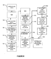
Fig. 5 is a logical flowchart depicting an embodiment of a method 500 for handling single failure GPS faults. In one aspect, the method is performed on a processing system, such as thehigh integrity system 112. In another aspect, the method is performed on a distributed processing system. - At 502, at least two sets of GPS reference measurements, at least 1 remote (user) GPS set of measurements, and optional IMU measurement data sets are received at the
processor 202 of thehigh integrity system 112. In one aspect, the GPS reference measurement sets include one or more unfaulted measurements. At 506, thehigh integrity system 112 calculates an H1 integrity risk assuming an undetected ephemeris fault. A first unbiased protection level is determined at 508. In one aspect, the first unbiased protection level is based on a first overall integrity requirement. The first overall integrity requirement is further based on the at least two sets of GPS reference measurements and the calculated H1 integrity risk. Thehigh integrity system 112 determines maximum ephemeris error at 510. At 512, an H1 ephemeris error protection level is determined by adding the maximum ephemeris error to the first unbiased protection level. - In one aspect, the
high integrity system 112 also calculates a reference receiver H1 protection level. At 516, thehigh integrity system 112 determines a second unbiased protection level based on a second overall integrity requirement assuming an undetected reference receiver fault. The second overall integrity requirement is based on the measurements from one or more unfaulted reference receivers and the H1 integrity PL risk. Thehigh integrity system 112 determines an H1 solution at 518. At 520 an H0 protection level is determined. At 522, thehigh integrity system 112 determines an H1 receiver fault protection level by adding the absolute value of the difference between the determined H0 position solution and the H1 position solution to the second unbiased protection level. - In one aspect, the
high integrity system 112 also calculates an IMU H1 protection level. At 524, the system determines a third unbiased protection level based on a second overall integrity requirement assuming an undetected IMU fault. The third overall integrity requirement is based on the measurements from one or more unfaulted reference receivers and the H1 integrity PL risk. At 526,high integrity system 112 determines the IMU B-value in the position domain. At 528,high integrity system 112 determines anH 1 IMU fault protection level by adding the absolute value of the IMU B-value to the third unbiased protection level. Thehigh integrity system 112 determines an overall protection level based on the H1 ephemeris fault protection level, the H0 protection level, the H1 receiver fault protection level, and the H1 IMU fault protection level further increasing the integrity level of the system at 530. - While only selected embodiments have been chosen to illustrate the present invention, it will be apparent to those skilled in the art from this disclosure that various changes and modifications can be made herein without departing from the scope of the invention as defined in the appended claims. Furthermore, the foregoing descriptions of the embodiments according to the present invention are provided for illustration only, and not for the purpose of limiting the invention as defined by the appended claims and their equivalents.
- The description above includes example systems, methods, techniques, instruction sequences, and/or computer program products that embody techniques of the present disclosure. However, it is understood that the described disclosure may be practiced without these specific details.
- In the present disclosure, the methods disclosed may be implemented as sets of instructions or software readable by a device. Further, it is understood that the specific order or hierarchy of steps in the methods disclosed are instances of example approaches. Based upon design preferences, it is understood that the specific order or hierarchy of steps in the method can be rearranged while remaining within the disclosed subject matter. The accompanying method claims present elements of the various steps in a sample order, and are not necessarily meant to be limited to the specific order or hierarchy presented.
- The described disclosure may be provided as a computer program product, or software, that may include a machine-readable medium having stored thereon instructions, which may be used to program a computer system (or other electronic devices) to perform a process according to the present disclosure. A machine-readable medium includes any mechanism for storing information in a form (e.g., software, processing application) readable by a machine (e.g., a computer). The machine-readable medium may include, but is not limited to, magnetic storage medium (e.g., floppy diskette), optical storage medium (e.g., CD-ROM); magneto-optical storage medium, read only memory (ROM); random access memory (RAM); erasable programmable memory (e.g., EPROM and EEPROM); flash memory; or other types of medium suitable for storing electronic instructions.
- It is believed that the present disclosure and many of its attendant advantages will be understood by the foregoing description, and it will be apparent that various changes may be made in the form, construction and arrangement of the components without departing from the disclosed subject matter or without sacrificing all of its material advantages. The form described is merely explanatory, and it is the intention of the following claims to encompass and include such changes.
- While the present disclosure has been described with reference to various embodiments, it will be understood that these embodiments are illustrative and that the scope of the disclosure is not limited to them. Many variations, modifications, additions, and improvements are possible. More generally, embodiments in accordance with the present disclosure have been described in the context of particular implementations. Functionality may be separated or combined in blocks differently in various embodiments of the disclosure or described with different terminology. These and other variations, modifications, additions, and improvements may fall within the scope of the disclosure as defined in the claims that follow.
- Those skilled in the art will appreciate that variations from the specific embodiments disclosed above are contemplated by the invention. The following invention should not be restricted to the above embodiments, but should be measured by the following claims.
Claims (15)
- A method for processing single failure GPS receiver faults, the method comprising:receiving, at a processor, at least two sets of GPS reference measurements and at least one set of remote user GPS measurements;determining, at the processor, a GPS relative positioning solution (H0 solution) based on the at least two sets of GPS reference measurements and the at least one set of remote user GPS measurements;excluding a particular set of the at least two sets of GPS reference measurements from the GPS relative positioning solution (H0 solution) to obtain an excluded GPS measurement data set, at the processor;excluding a different set of the at least two sets of GPS reference measurements from the GPS relative positioning solution (H0 solution) to obtain at least one other excluded GPS reference measurement data set, at the processor;calculating, at the processor, a H1 protection level based on a priori probability of a single failure GPS receiver fault;calculating, at the processor, at least one other H1 protection level based on a priori probability of a single failure GPS receiver fault and the bias between the excluded solution and the H0 solution;identifying a maximum of the H1 protection level and the at least one other H1 protection level to determine a final H1 protection level, at the processor and the bias between the excluded solution and the H0 solution;determining one or more overall protection levels based on the final H1 protection level, at the processor; andverifying an integrity requirement based on the overall protection levels, at the processor.
- The method of claim 1, wherein determining the H1 protection level and the at least one other H1 protection level based on a priori probability further comprises:determining a GPS positioning solution (H1 solution);determining one or more position-domain absolute differences (H1 bias) between the GPS positioning solution (H1 solution)and the GPS relative positioning solution (H0 solution);andadding the H1 bias to the H1 protection level and the at least one other H1 protection level to determine the final H1 protection level for the excluded set of GPS reference measurements and the at least one other excluded set of GPS reference measurements.
- The method of claim 1, wherein determining the one or more overall protection levels includes calculating an H0 protection level.
- The method of claim 1, wherein the protection levels are determined in the position domain.
- The method of claim 3, wherein the one or more overall protection levels are the maximum H0 protection level and the maximum H1 protection level.
- The method of claim 1, wherein determining when a single GPS receiver fault exists is based on the at least two sets of GPS references.
- The method of claim 1, wherein the GPS relative positioning solution (H0 solution) and the GPS positioning solution (H1 solution) and their associated protection levels are determined by GERAFS processing.
- The method of claim 1, wherein the GPS relative positioning solution (H0 solution) and the GPS positioning solution (H1 solution) and their associated protection levels are determined using a carrier-smoothed-code solution.
- The method of claim 1, wherein the GPS relative positioning solution (H0 solution) and the GPS positioning solution (H1 solution) and their associated protection levels are determined using a combination of GERAFS and carrier-smoothed-code solutions.
- A method for processing single failure GPS faults, the method comprising:determining an H1 integrity risk at a processor;determining an overall integrity allocation at the processor;calculating an unbiased relative positioning solution (H0 solution) at the processor;calculating a biased relative positioning solution (H1) under a single failure GPS fault at the processor;determining position-domain absolute differences (H1 bias) between the H1 solution and the H0 solution, at the processor;calculating a H1 protection level based on a priori probability for a single failure GPS faults, at the processor;calculating a final H1 protection level by adding the H1 bias to the H1 protection level, at the processor;calculating, at the processor, an overall protection levels based on the final H1 protection level; andverifying, at the processor, an integrity requirement based on the one or more overall protection levels.
- The method of claim 10, wherein the type of the single fault is an ephemeris error, the method further comprising:determining a maximum ephemeris error;determining relative positioning solution under the maximum ephemeris error; anddetermining relative positioning solution under biased GPS measurements.
- The method of claim 10, wherein the H1 integrity risk is a product of an ephemeris fault onset risk, an ephemeris fault exposure time, and an H1 protection level risk.
- The method of claim 10, wherein the H 1 integrity risk is a product of an inertial measurement unit (IMU) fault onset risk, an IMU fault exposure time, and an H1 protection level risk.
- The method of claim 10, wherein calculating the one or more overall protection levels comprises calculating an H0 protection level.
- The method of claim 10, wherein the each protection level is calculated in the position domain.
Applications Claiming Priority (1)
| Application Number | Priority Date | Filing Date | Title |
|---|---|---|---|
| US13/216,130 US20130050020A1 (en) | 2011-08-23 | 2011-08-23 | Method to handle single failure gps faults in high integrity relative positioning systems |
Publications (1)
| Publication Number | Publication Date |
|---|---|
| EP2562559A1 true EP2562559A1 (en) | 2013-02-27 |
Family
ID=46980711
Family Applications (1)
| Application Number | Title | Priority Date | Filing Date |
|---|---|---|---|
| EP12173254A Withdrawn EP2562559A1 (en) | 2011-08-23 | 2012-06-22 | Method to handle single failure GPS fault in high integrity relative positioning systems |
Country Status (2)
| Country | Link |
|---|---|
| US (1) | US20130050020A1 (en) |
| EP (1) | EP2562559A1 (en) |
Families Citing this family (28)
| Publication number | Priority date | Publication date | Assignee | Title |
|---|---|---|---|---|
| US9829582B2 (en) | 2011-09-19 | 2017-11-28 | Raytheon Company | Method and apparatus for differential global positioning system (DGPS)-based real time attitude determination (RTAD) |
| US9933528B2 (en) | 2014-10-27 | 2018-04-03 | Swift Navigation, Inc. | Systems and methods for real time kinematic satellite positioning |
| US10551196B2 (en) | 2015-04-30 | 2020-02-04 | Raytheon Company | Sensor installation monitoring |
| US10114126B2 (en) | 2015-04-30 | 2018-10-30 | Raytheon Company | Sensor installation monitoring |
| US10416315B2 (en) * | 2017-03-07 | 2019-09-17 | Honeywell International Inc. | False alarm distribution in advanced receiver autonomous integrity monitoring |
| US10677933B1 (en) * | 2017-08-09 | 2020-06-09 | Rockwell Collins, Inc. | Heading or pitch determination systems and methods with high confidence error bounds |
| US10473790B2 (en) | 2017-11-17 | 2019-11-12 | Swift Navigation, Inc. | Systems and methods for distributed dense network processing of satellite positioning data |
| US10578747B2 (en) | 2017-12-14 | 2020-03-03 | Swift Navigation, Inc. | Systems and methods for reduced-outlier satellite positioning |
| CN109900300B (en) * | 2019-03-27 | 2020-12-04 | 北京航空航天大学 | An integrated navigation integrity monitoring system for unmanned aerial vehicles |
| US11143765B2 (en) * | 2019-04-25 | 2021-10-12 | Honeywell International Inc. | Reducing bias impact on GNSS integrity |
| EP3963352A4 (en) | 2019-05-01 | 2023-09-20 | Swift Navigation, Inc. | Systems and methods for high-integrity satellite positioning |
| WO2021022251A1 (en) | 2019-08-01 | 2021-02-04 | Swift Navigation, Inc. | System and method for gaussian process enhanced gnss corrections generation |
| WO2021119493A1 (en) | 2019-12-11 | 2021-06-17 | Swift Navigation, Inc. | System and method for validating gnss ambiguities |
| EP4103973A4 (en) | 2020-02-14 | 2024-06-05 | Swift Navigation, Inc. | System and method for reconverging gnss position estimates |
| CN116075747A (en) | 2020-06-09 | 2023-05-05 | 斯威夫特导航股份有限公司 | Systems and methods for satellite positioning |
| WO2022015744A1 (en) | 2020-07-13 | 2022-01-20 | Swift Navigation, Inc. | System and method for determining gnss positioning corrections |
| WO2022046317A2 (en) | 2020-07-17 | 2022-03-03 | Swift Navigation, Inc. | System and method for providing gnss corrections |
| CN112596080B (en) * | 2020-11-25 | 2024-04-16 | 中国人民解放军93216部队 | Method for testing integrity index of unmanned aerial vehicle differential Beidou lifting guide system |
| CN112526549B (en) * | 2020-12-01 | 2022-03-15 | 北京航空航天大学 | Integrity fault identification method and system for ground enhancement system |
| US11550067B2 (en) | 2020-12-17 | 2023-01-10 | Swift Navigation, Inc. | System and method for fusing dead reckoning and GNSS data streams |
| US11733397B2 (en) | 2021-07-24 | 2023-08-22 | Swift Navigation, Inc. | System and method for computing positioning protection levels |
| US11693120B2 (en) | 2021-08-09 | 2023-07-04 | Swift Navigation, Inc. | System and method for providing GNSS corrections |
| US20230184956A1 (en) | 2021-12-10 | 2023-06-15 | Swift Navigation, Inc. | System and method for correcting satellite observations |
| US11860287B2 (en) | 2022-03-01 | 2024-01-02 | Swift Navigation, Inc. | System and method for detecting outliers in GNSS observations |
| WO2023167899A1 (en) | 2022-03-01 | 2023-09-07 | Swift Navigation, Inc. | System and method for fusing sensor and satellite measurements for positioning determination |
| US12013468B2 (en) | 2022-09-01 | 2024-06-18 | Swift Navigation, Inc. | System and method for determining GNSS corrections |
| WO2024058999A1 (en) | 2022-09-12 | 2024-03-21 | Swift Navigation, Inc. | System and method for gnss correction transmission |
| US12498493B2 (en) | 2022-10-21 | 2025-12-16 | Swift Navigation, Inc. | System and method for distributed integrity monitoring |
Citations (3)
| Publication number | Priority date | Publication date | Assignee | Title |
|---|---|---|---|---|
| US776845A (en) | 1904-02-09 | 1904-12-06 | Johnson Hughes | Bar-head-forging mechanism. |
| US7711482B2 (en) * | 2006-10-06 | 2010-05-04 | Thales | Hybrid INS/GNSS system with integrity monitoring and method for integrity monitoring |
| US7768451B2 (en) | 2007-07-23 | 2010-08-03 | Raytheon Company | Methods and apparatus for geometry extra-redundant almost fixed solutions |
Family Cites Families (4)
| Publication number | Priority date | Publication date | Assignee | Title |
|---|---|---|---|---|
| US7219013B1 (en) * | 2003-07-31 | 2007-05-15 | Rockwell Collins, Inc. | Method and system for fault detection and exclusion for multi-sensor navigation systems |
| US7436354B2 (en) * | 2006-09-07 | 2008-10-14 | The Mitre Corporation | Methods and systems for mobile navigational applications using global navigation satellite systems |
| GB0901685D0 (en) * | 2009-01-31 | 2009-03-11 | Qinetiq Ltd | Navigation system integrity |
| EP2402785B1 (en) * | 2010-06-23 | 2013-04-03 | Astrium GmbH | An improved RAIM algorithm |
-
2011
- 2011-08-23 US US13/216,130 patent/US20130050020A1/en not_active Abandoned
-
2012
- 2012-06-22 EP EP12173254A patent/EP2562559A1/en not_active Withdrawn
Patent Citations (3)
| Publication number | Priority date | Publication date | Assignee | Title |
|---|---|---|---|---|
| US776845A (en) | 1904-02-09 | 1904-12-06 | Johnson Hughes | Bar-head-forging mechanism. |
| US7711482B2 (en) * | 2006-10-06 | 2010-05-04 | Thales | Hybrid INS/GNSS system with integrity monitoring and method for integrity monitoring |
| US7768451B2 (en) | 2007-07-23 | 2010-08-03 | Raytheon Company | Methods and apparatus for geometry extra-redundant almost fixed solutions |
Non-Patent Citations (1)
| Title |
|---|
| SAYIM I ET AL: "Overbounding non-zero mean gaussian ranging error for navigation integrity of LAAS", RECENT ADVANCES IN SPACE TECHNOLOGIES, 2005. RAST 2005. PROCEEDINGS OF 2ND INTERNATIONAL CONFERENCE ON ISTANBUL, TURKEY JUNE 9-11, 2005, PISCATAWAY, NJ, USA,IEEE, 9 June 2005 (2005-06-09), pages 404 - 410, XP010838606, ISBN: 978-0-7803-8977-9 * |
Also Published As
| Publication number | Publication date |
|---|---|
| US20130050020A1 (en) | 2013-02-28 |
Similar Documents
| Publication | Publication Date | Title |
|---|---|---|
| US20130050020A1 (en) | Method to handle single failure gps faults in high integrity relative positioning systems | |
| EP2784445B1 (en) | Selected aspects of advanced receiver autonomous integrity monitoring application to kalman filter based navigation filter | |
| EP3730971B1 (en) | Reducing bias impact on gnss integrity | |
| ES2498720T3 (en) | Method and apparatus for determining an integrity indication parameter indicating the integrity of the positioning information determined in a global positioning system | |
| EP2160624B1 (en) | Geofencing and route adherence in global positioning system with signals from fewer than three satellites | |
| EP2068166B1 (en) | Navigation system with apparatus for detecting accuracy failures | |
| US10416315B2 (en) | False alarm distribution in advanced receiver autonomous integrity monitoring | |
| Rodriguez-Solano et al. | Protection level of the trimble RTX positioning engine for autonomous applications | |
| JP2008014938A (en) | System and method for enhancing satellite navigation receiver performance | |
| EP2685214A2 (en) | Multiple truth reference system and method | |
| BR112015011292B1 (en) | Method for estimating health parameters for global navigation satellite measurements implemented by a global navigation device and associated device | |
| EP4242693A1 (en) | Method for estimating multipath error of pseudo-range measurement value, and positioning method using same | |
| CN110398758A (en) | Detection of Gross Errors method, apparatus, equipment and storage medium in real-time clock bias estimation | |
| CN111812680B (en) | Integrity monitoring of primary and derived parameters | |
| Liu et al. | HPL calculation improvement for Chi-squared residual-based ARAIM | |
| CN112198533A (en) | System and method for evaluating integrity of foundation enhancement system under multiple hypotheses | |
| Lai et al. | Prototyping integrity monitors for ppp fault detections | |
| JP5566598B2 (en) | Navigation system comprising a device for detecting inaccuracy | |
| Osechas et al. | Carrier‐Phase Acceleration RAIM for GNSS Satellite Clock Fault Detection | |
| US11073620B2 (en) | Alternate uncertainty limits in the presence of a detected satellite fault | |
| EP3882665B1 (en) | Implementing single differences within a solution separation framework | |
| KR20130037838A (en) | Apparatus and method for monitoring gps satellite fault | |
| US20190049590A1 (en) | Method for Determining Protection Levels of Navigation Solutions, Associated Computer Program Product and Receiver | |
| CN114545456A (en) | Method and equipment for monitoring autonomous integrity of dual-antenna receiver of land-based positioning system | |
| Ochieng et al. | User level integrity monitoring and quality control for high accuracy positioning using GPS/INS measurements |
Legal Events
| Date | Code | Title | Description |
|---|---|---|---|
| PUAI | Public reference made under article 153(3) epc to a published international application that has entered the european phase |
Free format text: ORIGINAL CODE: 0009012 |
|
| AK | Designated contracting states |
Kind code of ref document: A1 Designated state(s): AL AT BE BG CH CY CZ DE DK EE ES FI FR GB GR HR HU IE IS IT LI LT LU LV MC MK MT NL NO PL PT RO RS SE SI SK SM TR |
|
| AX | Request for extension of the european patent |
Extension state: BA ME |
|
| 17P | Request for examination filed |
Effective date: 20130827 |
|
| RBV | Designated contracting states (corrected) |
Designated state(s): AL AT BE BG CH CY CZ DE DK EE ES FI FR GB GR HR HU IE IS IT LI LT LU LV MC MK MT NL NO PL PT RO RS SE SI SK SM TR |
|
| 17Q | First examination report despatched |
Effective date: 20140509 |
|
| STAA | Information on the status of an ep patent application or granted ep patent |
Free format text: STATUS: THE APPLICATION IS DEEMED TO BE WITHDRAWN |
|
| 18D | Application deemed to be withdrawn |
Effective date: 20141120 |