EP2562446A1 - Pulley device with a damping element - Google Patents
Pulley device with a damping element Download PDFInfo
- Publication number
- EP2562446A1 EP2562446A1 EP11306071A EP11306071A EP2562446A1 EP 2562446 A1 EP2562446 A1 EP 2562446A1 EP 11306071 A EP11306071 A EP 11306071A EP 11306071 A EP11306071 A EP 11306071A EP 2562446 A1 EP2562446 A1 EP 2562446A1
- Authority
- EP
- European Patent Office
- Prior art keywords
- pulley
- pulley device
- torque transmission
- radial
- damping element
- Prior art date
- Legal status (The legal status is an assumption and is not a legal conclusion. Google has not performed a legal analysis and makes no representation as to the accuracy of the status listed.)
- Withdrawn
Links
Images

Classifications
-
- F—MECHANICAL ENGINEERING; LIGHTING; HEATING; WEAPONS; BLASTING
- F16—ENGINEERING ELEMENTS AND UNITS; GENERAL MEASURES FOR PRODUCING AND MAINTAINING EFFECTIVE FUNCTIONING OF MACHINES OR INSTALLATIONS; THERMAL INSULATION IN GENERAL
- F16H—GEARING
- F16H55/00—Elements with teeth or friction surfaces for conveying motion; Worms, pulleys or sheaves for gearing mechanisms
- F16H55/32—Friction members
- F16H55/36—Pulleys
-
- F—MECHANICAL ENGINEERING; LIGHTING; HEATING; WEAPONS; BLASTING
- F16—ENGINEERING ELEMENTS AND UNITS; GENERAL MEASURES FOR PRODUCING AND MAINTAINING EFFECTIVE FUNCTIONING OF MACHINES OR INSTALLATIONS; THERMAL INSULATION IN GENERAL
- F16H—GEARING
- F16H55/00—Elements with teeth or friction surfaces for conveying motion; Worms, pulleys or sheaves for gearing mechanisms
- F16H55/32—Friction members
- F16H55/36—Pulleys
- F16H2055/366—Pulleys with means providing resilience or vibration damping
Definitions
- the present invention relates to the field of torque transmission devices used in particular in belt-driven rotary machines, for example motor vehicle air conditioning compressors.
- a belt-driven pulley drives the transmission spindle of the compressor via a torque transmission plate.
- the pulley is mounted on the outer ring of a rolling bearing, the inner ring of which is secured to a hollow shaft of the compressor housing. This type of device is described particularly in document FR 2 790 521 .
- One aim of the present invention is therefore to overcome the aforementioned drawbacks.
- a pulley device for a rotary machine especially a compressor, comprises a pulley, a rolling bearing, a torque transmission element designed to be mounted on a rotary spindle of the rotary machine. Said pulley is mounted on an outer ring of the rolling bearing and on the torque transmission element.
- the torque transmission element comprises a damping element made of an elastically deformable metallic material.
- Such a damping element improves the service life of the belt and the pulley by damping the vibrations between the pulley and the rotary spindle.
- the damping element comprises at least one radially projecting portion adapted to cooperate with at least one cavity radially located on the pulley, for example on its periphery.
- the cavity of the pulley cooperating with said damping element may have a slope so that if the torque transmission element transmits a torque exceeding a threshold value, the damping element is liable to unhook from the cavity of the pulley.
- the damping element is a helical spring having windings capable of deforming in a circumferential direction.
- the torque transmission element comprises a torque transmission plate having a radial plate provided with at least one radially extending tongue adapted to cooperate with a winding of the helical spring.
- each end winding of the helical spring comprises a radially projecting portion, one projecting portion being adapted to cooperate with a lug located on the radial plate, and the other projecting portion being adapted to cooperate with the cavity of the pulley.
- the radial plate comprises a series of slotted holes made through the radial plate forming annular portions centred on one and the same circle, angularly equidistant and tangential to the periphery of the radial plate.
- said torque transmission plate is made of a stamped metal sheet.
- the torque transmission plate is obtained by injecting a plastic material such as a polyamide, or by moulding a metallic material such as Aluminium based light alloy.
- the damping element comprises an axial sleeve designed to be mounted on the rotary spindle of the rotary machine and radial twisted blades extending radially from the axial sleeve and cooperating with a cavity of the pulley.
- each blade is flexile and elastically deformable in a circumferential direction, so that the vibrations between the rotary spindle and the pulley are damped.
- each cavity of the pulley may comprise a noise damper between the end of each radial twisted blade and the pulley.
- the damping element is made of a stamped metal sheet, and the pulley is overmoulded on the outer ring of the rolling bearing.
- a rotary machine comprising a static hollow shaft, a rotary spindle, and a pulley device described above.
- a pulley device designed by general reference number 10, is designed to be mounted on a compressor 20 comprising a housing or casing 21 that does not rotate, and a transmission spindle 22 capable of rotating about an axis 23.
- the transmission spindle 22 may be provided with a stepped end 22a ending in a threaded portion 22b so that it can interact with a nut 24.
- the stepped end 22a, of a smaller cross section than the cross section of the spindle 22, is delimited by a shoulder 22c.
- the transmission spindle 22 passes through a hollow shaft 25 of the housing 21, coaxial with the transmission spindle 22.
- the pulley device 10 comprises a pulley 11, a rolling bearing 12 and a torque transmission element 13.
- the pulley 11 has an outer surface 11a designed to cooperate with a belt (not illustrated), a bore 11b, and two lateral radial surfaces 11c and 11d, the surface 11d being arranged facing the casing 21, and the surface 11c being arranged on the opposite side to the casing 21 and longitudinally facing the hollow shaft 25.
- the outer surface 11a may have annular ribs to collaborate with a belt of the poly-V type for example.
- the bore 11b may have the form of annular ribs.
- the pulley 11 may comprise a plurality of stiffening ribs 11e.
- the pulley 11 may be made of resin material, for example based on polyamide, phenolic resin or alternatively polyurethane, or of metallic material, such as for example, light alloy.
- the rolling bearing 12 comprises an inner ring 14, an outer ring 15, at least one row of rolling elements 12a, a cage 12b to maintain uniform circumferential spacing of the rolling elements 12a and two seals 12c and 12d.
- the inner ring 14 comprises an outer surface 14a of revolution, a bore 14b in contact with an axial surface 25a of the hollow shaft 25 of the casing 21, and two lateral radial surfaces 14c and 14d, the lateral surface 14d being in contact with a radial surface 25b of the shaft 25, for example a shoulder.
- a raceway 14e of toroidal shape is formed by machining from the outer surface 14a.
- the outer ring 15 comprises an outer surface 15a, a bore 15b and two transverse radial surfaces 15c and 15d respectively aligned with the radial surfaces 14c and 14d.
- a raceway 15e is created by machining from the bore 15b.
- the raceway 15e is of toroidal shape.
- Annular slots are formed on the outer surface 15a of the outer ring 15 in order to have complementary shape of the bore 11b of the pulley 11.
- the pulley 11 can be overmoulded on the outer ring 15 of the rolling bearing 12. This results in excellent cohesion between these two components.
- the rolling elements 12a for example balls, are positioned between the raceways 14e and 15e of the inner 14 and outer 15 rings.
- the seals 12c and 12d can be force-fitted into slots formed from the bore 15b and near the radial surfaces 15c and 15d of the outer ring 15.
- the torque transmitting element 13 comprises a torque transmission plate 16 and a damping element 17.
- the torque transmission plate 16 made of a stamped metal sheet, comprises a sleeve tube 16a mounted on the end 22a of the transmission spindle 22 and a radial plate 16b extending radially from the axial sleeve 16a towards the outside and having the general shape of a disc.
- the sleeve tube 16a may be clamped between the nut 24 possibly supplemented by a washer 24a, and the shoulder 22c of the spindle 22, against which it bears via an axial end surface 16c of the sleeve tube 16a.
- the radial plate 16b extends radially in the overall form of a disc out to an external circumference.
- the radial plate diameter may be smaller than the maximum diameter of the pulley 11.
- the radial plate 16b of the torque transmission element 13 comprises a first series of slotted holes 16d made axially through the radial plate 16b. As illustrated on Figures 1 and 2 , these slotted holes 16d, in the form of four annular portions centred on one and the same circle, are angularly equidistant and tangential to the outer surface of the radial plate 16b. As an alternative, it is possible to have two diametrically opposed slotted holes or a number of slotted holes smaller or greater than four. It is possible to conceive of different shapes of slotted holes, for example round drillings or trapezoidal drillings. Such slotted holes 16d are drilled through the thickness of the radial plate 16b so as to cooperate with a fitting tool (not illustrated) for axially fitting the rolling bearing 12 and the pulley 11 onto a hollow shaft 25 of the housing.
- a fitting tool not illustrated
- the radial plate 16b of the torque transmission element 13 further comprises on its periphery, radially extending tongues 18 extending radially from the periphery of the radial plate 16b towards the outside by a first portion 18a slightly tilted and a radial portion 18b and a lug 19 projecting radially from the radial plate 16b towards the outside.
- the lug 19 comprises a slot 19a adapted to cooperate with the damping element 17.
- the damping element 17, illustrated in details in Figure 4 is made of an elastically deformable metallic material, such as steel.
- the damping element 17 is a helical spring having windings capable of deforming in a circumferential direction. Each end windings of the helical spring 17 comprises a radially projecting portion, such as hooks 17a, 17b.
- the first radially projecting portion 17a extends towards the pulley 11, whereas the second radially projecting portion 17b extends towards the inside of the spring 17.
- the first radially projecting portion 17a is adapted to cooperate with a cavity 11f located on a radial protrusion 11g extending on the periphery of the pulley 11 from the outer surface 11a towards the inside.
- the second radially projecting portion 17b is adapted to cooperate with the slot 19a of the lug 19 of the radial plate 16b.
- the helical spring 17 is stretched in order to be hooked to the pulley 11.
- the cavity 11f of the pulley 11 provides a slope so that if the spring 17 transmits a torque exceeding a threshold value V, such as 50 N.m, the first radially projecting portion 17a is liable to unhook from the cavity 11f.
- a pulley device designed by general reference number 30, is designed to be mounted on a compressor 20 comprising a housing or casing 21 that does not rotate, and a transmission spindle 22 capable of rotating about an axis 23.
- the transmission spindle 22 may be provided with a stepped end 22a ending in a threaded portion 22b so that it can interact with a nut 24.
- the stepped end 22a, of a smaller cross section than the cross section of the spindle 22, is delimited by a shoulder 22c.
- the transmission spindle 22 passes through a hollow shaft 25 of the housing 21, coaxial with the transmission spindle 22.
- the pulley device 30 comprises a pulley 31, a rolling bearing 32 and a torque transmission element 33.
- the pulley 31 has an outer surface 31a designed to cooperate with a belt (not illustrated), a bore 31b, and two lateral radial surfaces 31c and 31d, the surface 31d being arranged facing the casing 21, and the surface 31c being arranged on the opposite side to the casing 21.
- the outer surface 31a may have annular ribs to collaborate with a belt of the poly-V type for example.
- the bore 31b may have the form of annular ribs.
- the pulley 31 may be made of resin material, for example based on polyamide, phenolic resin or alternatively polyurethane, or of metallic material, for example, light alloy.
- the rolling bearing 32 comprises an inner ring 34, an outer ring 35, at least one row of rolling elements 36, a cage 37 to maintain uniform circumferential spacing of the rolling elements 36 and two seals 38a and 38b.
- the inner ring 34 comprises an outer surface 34a of revolution, a bore 34b in contact with an axial surface 25a of the hollow shaft 25 of the casing 21, and two lateral radial surfaces 34c and 34d, the lateral surface 34d being in contact with a radial surface 25b of the shaft 25, for example a shoulder.
- a raceway 34e of toroidal shape is formed by machining from the outer surface 34a.
- the outer ring 35 comprises an outer surface 35a, a bore 35b and two transverse radial surfaces 35c and 35d respectively aligned with the radial surfaces 34c and 34d.
- a raceway 35e is created by machining from the bore 35b.
- the raceway 35e is of toroidal shape.
- Annular slots are formed on the outer surface 35a of the outer ring 35 in order to have complementary shape of the bore 31b of the pulley 31.
- the pulley 31 can be overmoulded on the outer ring 35 of the rolling bearing 32. This results in excellent cohesion between these two components.
- the rolling elements 36 are positioned between the raceways 34e and 35e of the inner 34 and outer 35 rings.
- the seals 38a and 38b can be force-fitted into slots formed from the bore 35b and near the radial surfaces 35c and 35d of the outer ring 35.
- the torque transmitting element 33 comprises a damping element 39 made of a stamped metal sheet having an axial sleeve 39a mounted on the end 22a of the transmission spindle 22 and radial twisted blades 39b extending radially from the axial sleeve 39a towards the outside.
- the sleeve tube 39a may be clamped between the nut 24 possibly supplemented by a washer (not illustrated), and the shoulder 22c of the spindle 22, against which it bears via an axial end surface 39c of the sleeve tube 39a.
- the four radial twisted blades 39b are angularly equidistant and diametrically opposed. As an alternative, it is possible to have two radial blades 39b or a number of radial blades greater than four.
- the helical shape of the radial blades 39b provides a damping element 39 elastically deformable in a circumferential direction, in order to damp the vibrations between the rotary spindle 22 and the pulley 31.
- each radial blade 39b cooperate with a cavity 31e located on a radial protrusion 31f extending on the periphery of the pulley 31 from the outer surface 31a towards the inside.
- the blades 39b are stretched in order to be hooked to the pulley 31.
- the cavity 31e of the pulley 31 provides a slope so that if the damping element 39 transmits a torque exceeding a threshold value V, such as 50 N.m, the end of each radial twisted blade 39b are liable to unhook from the cavity 31e.
- each radial blade 39b In the unhooked position of the radial twisted blades 39b, shown in Figure 8 , each radial blade 39b returns in its rest position and does not transmits torque from the pulley 31 to the rotary spindle 22. Each end of the radial twisted blades 39b is unhooked from the cavity 31e and rests axially against the outer lateral surface 31g of the radial protrusion 31f of the pulley 31.
- each cavity 31e of the pulley 31 comprises a noise damper 33a, made of rubber material, in order to damp the vibrations between the blades 39b and the cavities 31 of the pulley 31.
- vibrations from the pulley to the rotary spindle and from the rotary spindle to the pulley are filtered by the damping element, thanks to its circumferential elasticity which can damp the acyclisms of the combustion engine and the vibrations from the rotary spindle.
- the pulley device according to the invention integrates thus two functions, a damping function and a torque limiter function, thanks to the shape of the damping element.
Landscapes
- Engineering & Computer Science (AREA)
- General Engineering & Computer Science (AREA)
- Mechanical Engineering (AREA)
- Pulleys (AREA)
Abstract
Pulley device for a rotary machine, especially a compressor (20), comprising a pulley (11), a rolling bearing (12), a torque transmission element (13) designed to be mounted on a rotary spindle (22) of the rotary machine (20), said pulley (11) being mounted on an outer ring (15) of the rolling bearing (12) and on the torque transmission element (13).
The torque transmission element (13) comprises a damping element (17) made of an elastically deformable metallic material.
Description
- The present invention relates to the field of torque transmission devices used in particular in belt-driven rotary machines, for example motor vehicle air conditioning compressors.
- In such compressor drive devices, a belt-driven pulley drives the transmission spindle of the compressor via a torque transmission plate. The pulley is mounted on the outer ring of a rolling bearing, the inner ring of which is secured to a hollow shaft of the compressor housing. This type of device is described particularly in document
FR 2 790 521 - However, since the belt-driven pulley is driven by an internal combustion engine of the motor vehicle, acyclisms resulting of the alternation between decompression and combustion phases are transmitted to the pulley, and to the transmission spindle of the compressor. Furthermore, vibrations of the rotation of the compressor spindle can also be transmitted to the pulley.
- One aim of the present invention is therefore to overcome the aforementioned drawbacks.
- It is a particular object of the present invention to provide a pulley device comprising means for filtering any vibrations from the pulley to the rotary spindle, and from the rotary spindle to the pulley.
- In one embodiment, a pulley device for a rotary machine, especially a compressor, comprises a pulley, a rolling bearing, a torque transmission element designed to be mounted on a rotary spindle of the rotary machine. Said pulley is mounted on an outer ring of the rolling bearing and on the torque transmission element.
- The torque transmission element comprises a damping element made of an elastically deformable metallic material.
- Such a damping element improves the service life of the belt and the pulley by damping the vibrations between the pulley and the rotary spindle.
- Advantageously, the damping element comprises at least one radially projecting portion adapted to cooperate with at least one cavity radially located on the pulley, for example on its periphery.
- The cavity of the pulley cooperating with said damping element may have a slope so that if the torque transmission element transmits a torque exceeding a threshold value, the damping element is liable to unhook from the cavity of the pulley.
- In one embodiment, the damping element is a helical spring having windings capable of deforming in a circumferential direction.
- Advantageously, the torque transmission element comprises a torque transmission plate having a radial plate provided with at least one radially extending tongue adapted to cooperate with a winding of the helical spring.
- For example, each end winding of the helical spring comprises a radially projecting portion, one projecting portion being adapted to cooperate with a lug located on the radial plate, and the other projecting portion being adapted to cooperate with the cavity of the pulley.
- Advantageously, the radial plate comprises a series of slotted holes made through the radial plate forming annular portions centred on one and the same circle, angularly equidistant and tangential to the periphery of the radial plate.
- Advantageously, said torque transmission plate is made of a stamped metal sheet.
- Alternatively, the torque transmission plate is obtained by injecting a plastic material such as a polyamide, or by moulding a metallic material such as Aluminium based light alloy.
- In another embodiment, the damping element comprises an axial sleeve designed to be mounted on the rotary spindle of the rotary machine and radial twisted blades extending radially from the axial sleeve and cooperating with a cavity of the pulley.
- Thanks to the helical shape of each blade, the blades are flexile and elastically deformable in a circumferential direction, so that the vibrations between the rotary spindle and the pulley are damped.
- Furthermore, each cavity of the pulley may comprise a noise damper between the end of each radial twisted blade and the pulley.
- Advantageously, the damping element is made of a stamped metal sheet, and the pulley is overmoulded on the outer ring of the rolling bearing.
- According to another aspect, it is proposed a rotary machine comprising a static hollow shaft, a rotary spindle, and a pulley device described above.
- The present invention will be better understood with the aid of the detailed description of a number of embodiments given by way of non-limiting examples and illustrated by the attached drawings, in which:
-
Figure 1 is a perspective view of a pulley device according to an embodiment of the invention, mounted on a compressor ; -
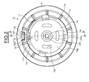
Figure 2 is a front view of the pulley device ofFigure 1 ; -
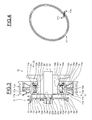
Figure 3 is an axial section, along line III-III ofFigure 2 ; -
Figure 4 is a perspective view of a damping element according toFigure 3 ; -
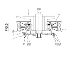
Figure 5 illustrates the damping element ofFigure 3 in an unhooked position; -
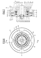
Figure 6 is a front view of a pulley device according to another embodiment of the invention, mounted on a compressor ; -
Figure 7 is an axial section, along line VII-VII ofFigure 6 ;
and -
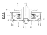
Figure 8 illustrates the damping element ofFigure 7 in an unhooked position. - As illustrated on
Figures 1 to 3 , a pulley device, designed bygeneral reference number 10, is designed to be mounted on acompressor 20 comprising a housing orcasing 21 that does not rotate, and atransmission spindle 22 capable of rotating about anaxis 23. As illustrated onFigure 3 , thetransmission spindle 22 may be provided with astepped end 22a ending in a threadedportion 22b so that it can interact with anut 24. Thestepped end 22a, of a smaller cross section than the cross section of thespindle 22, is delimited by ashoulder 22c. Thetransmission spindle 22 passes through ahollow shaft 25 of thehousing 21, coaxial with thetransmission spindle 22. - The
pulley device 10 comprises apulley 11, a rolling bearing 12 and atorque transmission element 13. Thepulley 11 has an outer surface 11a designed to cooperate with a belt (not illustrated), abore 11b, and two lateralradial surfaces surface 11d being arranged facing thecasing 21, and thesurface 11c being arranged on the opposite side to thecasing 21 and longitudinally facing thehollow shaft 25. The outer surface 11a may have annular ribs to collaborate with a belt of the poly-V type for example. Thebore 11b may have the form of annular ribs. Thepulley 11 may comprise a plurality ofstiffening ribs 11e. Thepulley 11 may be made of resin material, for example based on polyamide, phenolic resin or alternatively polyurethane, or of metallic material, such as for example, light alloy. - The rolling
bearing 12 comprises aninner ring 14, anouter ring 15, at least one row ofrolling elements 12a, acage 12b to maintain uniform circumferential spacing of therolling elements 12a and twoseals inner ring 14 comprises anouter surface 14a of revolution, abore 14b in contact with anaxial surface 25a of thehollow shaft 25 of thecasing 21, and two lateralradial surfaces lateral surface 14d being in contact with aradial surface 25b of theshaft 25, for example a shoulder. Araceway 14e of toroidal shape is formed by machining from theouter surface 14a. - The
outer ring 15 comprises anouter surface 15a, abore 15b and two transverseradial surfaces radial surfaces raceway 15e is created by machining from thebore 15b. Theraceway 15e is of toroidal shape. - Annular slots are formed on the
outer surface 15a of theouter ring 15 in order to have complementary shape of thebore 11b of thepulley 11. Thepulley 11 can be overmoulded on theouter ring 15 of the rollingbearing 12. This results in excellent cohesion between these two components. - The
rolling elements 12a, for example balls, are positioned between theraceways - The
seals bore 15b and near theradial surfaces outer ring 15. - The
torque transmitting element 13 comprises atorque transmission plate 16 and adamping element 17. - The
torque transmission plate 16, made of a stamped metal sheet, comprises asleeve tube 16a mounted on theend 22a of thetransmission spindle 22 and aradial plate 16b extending radially from theaxial sleeve 16a towards the outside and having the general shape of a disc. Thesleeve tube 16a may be clamped between thenut 24 possibly supplemented by awasher 24a, and theshoulder 22c of thespindle 22, against which it bears via anaxial end surface 16c of thesleeve tube 16a. - Starting from the end of the
sleeve tube 16a located axially at the opposite end from thecasing 21, theradial plate 16b extends radially in the overall form of a disc out to an external circumference. The radial plate diameter may be smaller than the maximum diameter of thepulley 11. - The
radial plate 16b of thetorque transmission element 13 comprises a first series of slottedholes 16d made axially through theradial plate 16b. As illustrated onFigures 1 and2 , these slottedholes 16d, in the form of four annular portions centred on one and the same circle, are angularly equidistant and tangential to the outer surface of theradial plate 16b. As an alternative, it is possible to have two diametrically opposed slotted holes or a number of slotted holes smaller or greater than four. It is possible to conceive of different shapes of slotted holes, for example round drillings or trapezoidal drillings. Such slottedholes 16d are drilled through the thickness of theradial plate 16b so as to cooperate with a fitting tool (not illustrated) for axially fitting the rollingbearing 12 and thepulley 11 onto ahollow shaft 25 of the housing. - The
radial plate 16b of thetorque transmission element 13 further comprises on its periphery, radially extendingtongues 18 extending radially from the periphery of theradial plate 16b towards the outside by afirst portion 18a slightly tilted and aradial portion 18b and alug 19 projecting radially from theradial plate 16b towards the outside. Thelug 19 comprises aslot 19a adapted to cooperate with the dampingelement 17. - The damping
element 17, illustrated in details inFigure 4 , is made of an elastically deformable metallic material, such as steel. The dampingelement 17 is a helical spring having windings capable of deforming in a circumferential direction. Each end windings of thehelical spring 17 comprises a radially projecting portion, such ashooks portion 17a extends towards thepulley 11, whereas the second radially projectingportion 17b extends towards the inside of thespring 17. The first radially projectingportion 17a is adapted to cooperate with acavity 11f located on aradial protrusion 11g extending on the periphery of thepulley 11 from the outer surface 11a towards the inside. The second radially projectingportion 17b is adapted to cooperate with theslot 19a of thelug 19 of theradial plate 16b. - As illustrated on
Figure 3 , thehelical spring 17 is stretched in order to be hooked to thepulley 11. Thecavity 11f of thepulley 11 provides a slope so that if thespring 17 transmits a torque exceeding a threshold value V, such as 50 N.m, the first radially projectingportion 17a is liable to unhook from thecavity 11f. - In the unhooked position of the
spring 17, shows inFigure 5 , thehelical spring 17 returns in its rest position. The first radially projectingportion 17a is unhooked from thecavity 11f and the winding of thespring 17 is axially retained by theradially extending tongues 18. - The embodiment shown in
Figures 6 to 8 , in which identical parts bear the same reference, is substantially similar to the embodiment ofFigures 1 to 5 . However, thepulley device 30 ofFigures 6 to 8 differs from thepulley 10 device ofFigures 1 to 5 . - As illustrated on
Figures 6 to 8 , a pulley device, designed bygeneral reference number 30, is designed to be mounted on acompressor 20 comprising a housing or casing 21 that does not rotate, and atransmission spindle 22 capable of rotating about anaxis 23. As illustrated onFigure 7 , thetransmission spindle 22 may be provided with a steppedend 22a ending in a threadedportion 22b so that it can interact with anut 24. The steppedend 22a, of a smaller cross section than the cross section of thespindle 22, is delimited by ashoulder 22c. Thetransmission spindle 22 passes through ahollow shaft 25 of thehousing 21, coaxial with thetransmission spindle 22. - The
pulley device 30 comprises apulley 31, a rolling bearing 32 and atorque transmission element 33. Thepulley 31 has anouter surface 31a designed to cooperate with a belt (not illustrated), a bore 31b, and two lateral radial surfaces 31c and 31d, thesurface 31d being arranged facing thecasing 21, and thesurface 31c being arranged on the opposite side to thecasing 21. Theouter surface 31a may have annular ribs to collaborate with a belt of the poly-V type for example. The bore 31b may have the form of annular ribs. Thepulley 31 may be made of resin material, for example based on polyamide, phenolic resin or alternatively polyurethane, or of metallic material, for example, light alloy. - The rolling bearing 32 comprises an
inner ring 34, anouter ring 35, at least one row of rollingelements 36, acage 37 to maintain uniform circumferential spacing of the rollingelements 36 and twoseals inner ring 34 comprises anouter surface 34a of revolution, abore 34b in contact with anaxial surface 25a of thehollow shaft 25 of thecasing 21, and two lateral radial surfaces 34c and 34d, thelateral surface 34d being in contact with aradial surface 25b of theshaft 25, for example a shoulder. Araceway 34e of toroidal shape is formed by machining from theouter surface 34a. - The
outer ring 35 comprises an outer surface 35a, abore 35b and two transverse radial surfaces 35c and 35d respectively aligned with the radial surfaces 34c and 34d. A raceway 35e is created by machining from thebore 35b. The raceway 35e is of toroidal shape. Annular slots are formed on the outer surface 35a of theouter ring 35 in order to have complementary shape of the bore 31b of thepulley 31. Thepulley 31 can be overmoulded on theouter ring 35 of the rolling bearing 32. This results in excellent cohesion between these two components. - The rolling
elements 36, for example balls, are positioned between theraceways 34e and 35e of the inner 34 and outer 35 rings. - The
seals bore 35b and near the radial surfaces 35c and 35d of theouter ring 35. - The
torque transmitting element 33 comprises a dampingelement 39 made of a stamped metal sheet having anaxial sleeve 39a mounted on theend 22a of thetransmission spindle 22 and radialtwisted blades 39b extending radially from theaxial sleeve 39a towards the outside. Thesleeve tube 39a may be clamped between thenut 24 possibly supplemented by a washer (not illustrated), and theshoulder 22c of thespindle 22, against which it bears via anaxial end surface 39c of thesleeve tube 39a. - As illustrated on
Figure 6 , the four radialtwisted blades 39b are angularly equidistant and diametrically opposed. As an alternative, it is possible to have tworadial blades 39b or a number of radial blades greater than four. - The helical shape of the
radial blades 39b provides a dampingelement 39 elastically deformable in a circumferential direction, in order to damp the vibrations between therotary spindle 22 and thepulley 31. - The end of each
radial blade 39b cooperate with acavity 31e located on aradial protrusion 31f extending on the periphery of thepulley 31 from theouter surface 31a towards the inside. As illustrated onFigure 7 , theblades 39b are stretched in order to be hooked to thepulley 31. Thecavity 31e of thepulley 31 provides a slope so that if the dampingelement 39 transmits a torque exceeding a threshold value V, such as 50 N.m, the end of each radial twistedblade 39b are liable to unhook from thecavity 31e. - In the unhooked position of the radial
twisted blades 39b, shown inFigure 8 , eachradial blade 39b returns in its rest position and does not transmits torque from thepulley 31 to therotary spindle 22. Each end of the radialtwisted blades 39b is unhooked from thecavity 31e and rests axially against the outerlateral surface 31g of theradial protrusion 31f of thepulley 31. - As illustrated on
Figures 7 and8 , eachcavity 31e of thepulley 31 comprises anoise damper 33a, made of rubber material, in order to damp the vibrations between theblades 39b and thecavities 31 of thepulley 31. - With the pulley device according to the invention, vibrations from the pulley to the rotary spindle and from the rotary spindle to the pulley are filtered by the damping element, thanks to its circumferential elasticity which can damp the acyclisms of the combustion engine and the vibrations from the rotary spindle.
- Furthermore, the pulley device according to the invention integrates thus two functions, a damping function and a torque limiter function, thanks to the shape of the damping element.
Claims (15)
- Pulley device for a rotary machine, especially a compressor (20), comprising a pulley (11, 31), a rolling bearing (12, 32), a torque transmission element (13, 33) designed to be mounted on a rotary spindle (22) of the rotary machine (20), said pulley (11, 31) being mounted on an outer ring (15, 35) of the rolling bearing (12, 32) and on the torque transmission element (13, 33), characterized in that the torque transmission element (13, 33) comprises a damping element (17, 39) made of an elastically deformable metallic material.
- Pulley device according to claim 1, in which the damping element (17, 39) comprises at least one radially projecting portion (17a, 39b) adapted to cooperate with at least one cavity (11f, 31e) radially located on the pulley (11, 31).
- Pulley device according to claim 2, in which the cavity (11f, 31e) of the pulley (11, 31) cooperating with the damping element (17, 39) has a slope so that if the torque transmission element (13, 33) transmits a torque exceeding a threshold value (V), the damping element (17, 39) is liable to unhook from the cavity (11f, 31e) of the pulley (11, 31).
- Pulley device according to any one of claims 1 to 3, in which the damping element (17) is a helical spring having windings capable of deforming in a circumferential direction.
- Pulley device according to claim 4, in which the torque transmission element (13) comprises a torque transmission plate (16) having a radial plate (16b) provided with at least one radially extending tongue (18) adapted to cooperate with a winding of the helical spring (17).
- Pulley device according to claims 2 and 5, in which each end winding of the helical spring (17) comprises a radially projecting portion (17a, 17b), one projecting portion (17b) being adapted to cooperate with a lug (19) located on the radial plate (16b), and the other projecting portion (17a) being adapted to cooperate with the cavity (11f) of the pulley (11).
- Pulley device according to claim 5 or 6, in which the radial plate (16b) comprises a series of slotted holes (16d) made through the radial plate (16b) forming annular portions centred on one and the same circle, angularly equidistant and tangential to the periphery of the radial plate (16b).
- Pulley device according to any one of claims 4 to 7, in which said torque transmission plate (16) is made of a stamped metal sheet.
- Pulley device according to any one of claims 4 to 7, in which said torque transmission plate (16) is obtained from injecting a plastic material, or by moulding a metallic material.
- Pulley device according to any one of claims 1 to 3, in which the damping element (39) comprises an axial sleeve (39a), designed to be mounted on the rotary spindle (22) of the rotary machine (20) and radial twisted blades (39b) extending radially from the axial sleeve (39a) and cooperating the pulley (31).
- Pulley device according to claims 2 and 10, in which radial twisted blades (39b) cooperate with one cavity (31e) of the pulley (31).
- Pulley device according to claim 11, in which each cavity (31e) of the pulley (31) comprises a noise damper (33a) between the end of each radial twisted blade (39b) and the pulley (31).
- Pulley device according to any one of claims 10 to 12, in which said damping element (39) is made of a stamped metal sheet.
- Pulley device according to any one of the preceding claims, in which the pulley (11, 31) is overmoulded on the outer ring (15, 35) of the rolling bearing (12, 32).
- Rotary machine comprising a static hollow shaft (25), a rotary spindle (22), and a pulley device (10, 30) according to any one of the preceding claims.
Priority Applications (1)
| Application Number | Priority Date | Filing Date | Title |
|---|---|---|---|
| EP11306071A EP2562446A1 (en) | 2011-08-26 | 2011-08-26 | Pulley device with a damping element |
Applications Claiming Priority (1)
| Application Number | Priority Date | Filing Date | Title |
|---|---|---|---|
| EP11306071A EP2562446A1 (en) | 2011-08-26 | 2011-08-26 | Pulley device with a damping element |
Publications (1)
| Publication Number | Publication Date |
|---|---|
| EP2562446A1 true EP2562446A1 (en) | 2013-02-27 |
Family
ID=44677806
Family Applications (1)
| Application Number | Title | Priority Date | Filing Date |
|---|---|---|---|
| EP11306071A Withdrawn EP2562446A1 (en) | 2011-08-26 | 2011-08-26 | Pulley device with a damping element |
Country Status (1)
| Country | Link |
|---|---|
| EP (1) | EP2562446A1 (en) |
Citations (4)
| Publication number | Priority date | Publication date | Assignee | Title |
|---|---|---|---|---|
| US6083130A (en) * | 1997-05-07 | 2000-07-04 | Litens Automotive Partnership | Serpentine drive system with improved over-running alternator decoupler |
| FR2790521A1 (en) | 1999-03-02 | 2000-09-08 | Sanden Corp | TORQUE TRANSMISSION MECHANISM FOR A COMPRESSOR USING AN ELASTIC RING FOR ITS ASSEMBLY |
| EP1764524A1 (en) * | 2005-09-19 | 2007-03-21 | Hutchinson | Power-transmitting pulley |
| WO2009047816A1 (en) * | 2007-10-12 | 2009-04-16 | Dayco Europe S.R.L. | Pulley assembly preferably for feeding an accessory member by means of a belt drive in an internal combustion engine |
-
2011
- 2011-08-26 EP EP11306071A patent/EP2562446A1/en not_active Withdrawn
Patent Citations (4)
| Publication number | Priority date | Publication date | Assignee | Title |
|---|---|---|---|---|
| US6083130A (en) * | 1997-05-07 | 2000-07-04 | Litens Automotive Partnership | Serpentine drive system with improved over-running alternator decoupler |
| FR2790521A1 (en) | 1999-03-02 | 2000-09-08 | Sanden Corp | TORQUE TRANSMISSION MECHANISM FOR A COMPRESSOR USING AN ELASTIC RING FOR ITS ASSEMBLY |
| EP1764524A1 (en) * | 2005-09-19 | 2007-03-21 | Hutchinson | Power-transmitting pulley |
| WO2009047816A1 (en) * | 2007-10-12 | 2009-04-16 | Dayco Europe S.R.L. | Pulley assembly preferably for feeding an accessory member by means of a belt drive in an internal combustion engine |
Similar Documents
| Publication | Publication Date | Title |
|---|---|---|
| US9062759B2 (en) | Pulley device with a damping element | |
| US9086139B2 (en) | Preassembled pulley device with elastic ring and method of mounting the device | |
| US20130337952A1 (en) | Pulley device for an air conditioning compressor | |
| EP1844245B1 (en) | Torque limited decoupler | |
| EP1692409B1 (en) | Spring travel limitor for overrunning decoupler | |
| US20130337953A1 (en) | Pulley device for an air conditioning compressor | |
| KR20070047792A (en) | Rotary vibration damping device | |
| US8632431B2 (en) | Drive wheel of an auxiliary unit belt drive of an internal combustion engine | |
| KR20110014670A (en) | Overrunning alternator decoupler pulley with bare wire spring and grease lubricant | |
| CN110651133A (en) | Filter Pulley Assemblies for Belt Drives | |
| US9410607B2 (en) | Pulley unit | |
| EP2562444A1 (en) | Pulley device with a torque limiter element | |
| KR100913630B1 (en) | Apparatus for transmitting a torque from motor to compressor | |
| US6796413B2 (en) | One-way clutch | |
| US20080090686A1 (en) | Disengageable pulley device | |
| KR20160038483A (en) | Alternator damper pulley for vehicle | |
| EP2781793A1 (en) | Pulley device and rotary machine comprising such a device | |
| EP2781792A1 (en) | Pulley device and rotary machine comprising such a device | |
| US20140073466A1 (en) | Pulley device, turning machine fitted with such a device and method of mounting such a device on a turning machine | |
| WO2010066572A1 (en) | Overrunning clutch for disengageable pulley device | |
| CN107559310A (en) | Release bearing retainer | |
| CN107131286B (en) | Driving part mounting structure and household appliance | |
| US7732960B2 (en) | Motor having thrust system | |
| JP4893997B2 (en) | One-way clutch | |
| JP2017160923A (en) | Power transmission device |
Legal Events
| Date | Code | Title | Description |
|---|---|---|---|
| PUAI | Public reference made under article 153(3) epc to a published international application that has entered the european phase |
Free format text: ORIGINAL CODE: 0009012 |
|
| AK | Designated contracting states |
Kind code of ref document: A1 Designated state(s): AL AT BE BG CH CY CZ DE DK EE ES FI FR GB GR HR HU IE IS IT LI LT LU LV MC MK MT NL NO PL PT RO RS SE SI SK SM TR |
|
| AX | Request for extension of the european patent |
Extension state: BA ME |
|
| STAA | Information on the status of an ep patent application or granted ep patent |
Free format text: STATUS: THE APPLICATION IS DEEMED TO BE WITHDRAWN |
|
| 18D | Application deemed to be withdrawn |
Effective date: 20130828 |