EP2562432A1 - Fixing means - Google Patents
Fixing means Download PDFInfo
- Publication number
- EP2562432A1 EP2562432A1 EP12177157A EP12177157A EP2562432A1 EP 2562432 A1 EP2562432 A1 EP 2562432A1 EP 12177157 A EP12177157 A EP 12177157A EP 12177157 A EP12177157 A EP 12177157A EP 2562432 A1 EP2562432 A1 EP 2562432A1
- Authority
- EP
- European Patent Office
- Prior art keywords
- clip
- fixing means
- fixing
- equipment element
- substrate
- Prior art date
- Legal status (The legal status is an assumption and is not a legal conclusion. Google has not performed a legal analysis and makes no representation as to the accuracy of the status listed.)
- Withdrawn
Links
- 239000000758 substrate Substances 0.000 claims abstract description 18
- 239000000463 material Substances 0.000 description 3
- 238000012544 monitoring process Methods 0.000 description 3
- 230000015572 biosynthetic process Effects 0.000 description 2
- 230000000694 effects Effects 0.000 description 2
- 238000005755 formation reaction Methods 0.000 description 2
- 239000012790 adhesive layer Substances 0.000 description 1
- 239000002131 composite material Substances 0.000 description 1
- 238000009434 installation Methods 0.000 description 1
- 239000002184 metal Substances 0.000 description 1
- 238000000034 method Methods 0.000 description 1
- 238000012986 modification Methods 0.000 description 1
- 230000004048 modification Effects 0.000 description 1
- 229920003023 plastic Polymers 0.000 description 1
- 239000004033 plastic Substances 0.000 description 1
- 238000000926 separation method Methods 0.000 description 1
Images



Classifications
-
- B—PERFORMING OPERATIONS; TRANSPORTING
- B64—AIRCRAFT; AVIATION; COSMONAUTICS
- B64C—AEROPLANES; HELICOPTERS
- B64C1/00—Fuselages; Constructional features common to fuselages, wings, stabilising surfaces or the like
- B64C1/40—Sound or heat insulation, e.g. using insulation blankets
- B64C1/403—Arrangement of fasteners specially adapted therefor, e.g. of clips
- B64C1/406—Arrangement of fasteners specially adapted therefor, e.g. of clips in combination with supports for lines, e.g. for pipes or cables
-
- F—MECHANICAL ENGINEERING; LIGHTING; HEATING; WEAPONS; BLASTING
- F16—ENGINEERING ELEMENTS AND UNITS; GENERAL MEASURES FOR PRODUCING AND MAINTAINING EFFECTIVE FUNCTIONING OF MACHINES OR INSTALLATIONS; THERMAL INSULATION IN GENERAL
- F16B—DEVICES FOR FASTENING OR SECURING CONSTRUCTIONAL ELEMENTS OR MACHINE PARTS TOGETHER, e.g. NAILS, BOLTS, CIRCLIPS, CLAMPS, CLIPS OR WEDGES; JOINTS OR JOINTING
- F16B7/00—Connections of rods or tubes, e.g. of non-circular section, mutually, including resilient connections
- F16B7/04—Clamping or clipping connections
- F16B7/0406—Clamping or clipping connections for rods or tubes being coaxial
- F16B7/0413—Clamping or clipping connections for rods or tubes being coaxial for tubes using the innerside thereof
- F16B7/042—Clamping or clipping connections for rods or tubes being coaxial for tubes using the innerside thereof with a locking element, e.g. pin, ball or pushbutton, engaging in a hole in the wall of at least one tube
-
- F—MECHANICAL ENGINEERING; LIGHTING; HEATING; WEAPONS; BLASTING
- F16—ENGINEERING ELEMENTS AND UNITS; GENERAL MEASURES FOR PRODUCING AND MAINTAINING EFFECTIVE FUNCTIONING OF MACHINES OR INSTALLATIONS; THERMAL INSULATION IN GENERAL
- F16L—PIPES; JOINTS OR FITTINGS FOR PIPES; SUPPORTS FOR PIPES, CABLES OR PROTECTIVE TUBING; MEANS FOR THERMAL INSULATION IN GENERAL
- F16L3/00—Supports for pipes, cables or protective tubing, e.g. hangers, holders, clamps, cleats, clips, brackets
- F16L3/08—Supports for pipes, cables or protective tubing, e.g. hangers, holders, clamps, cleats, clips, brackets substantially surrounding the pipe, cable or protective tubing
- F16L3/12—Supports for pipes, cables or protective tubing, e.g. hangers, holders, clamps, cleats, clips, brackets substantially surrounding the pipe, cable or protective tubing comprising a member substantially surrounding the pipe, cable or protective tubing
- F16L3/127—Supports for pipes, cables or protective tubing, e.g. hangers, holders, clamps, cleats, clips, brackets substantially surrounding the pipe, cable or protective tubing comprising a member substantially surrounding the pipe, cable or protective tubing and extending away from the attachment surface
-
- H—ELECTRICITY
- H02—GENERATION; CONVERSION OR DISTRIBUTION OF ELECTRIC POWER
- H02G—INSTALLATION OF ELECTRIC CABLES OR LINES, OR OF COMBINED OPTICAL AND ELECTRIC CABLES OR LINES
- H02G3/00—Installations of electric cables or lines or protective tubing therefor in or on buildings, equivalent structures or vehicles
- H02G3/30—Installations of cables or lines on walls, floors or ceilings
- H02G3/32—Installations of cables or lines on walls, floors or ceilings using mounting clamps
-
- Y—GENERAL TAGGING OF NEW TECHNOLOGICAL DEVELOPMENTS; GENERAL TAGGING OF CROSS-SECTIONAL TECHNOLOGIES SPANNING OVER SEVERAL SECTIONS OF THE IPC; TECHNICAL SUBJECTS COVERED BY FORMER USPC CROSS-REFERENCE ART COLLECTIONS [XRACs] AND DIGESTS
- Y10—TECHNICAL SUBJECTS COVERED BY FORMER USPC
- Y10T—TECHNICAL SUBJECTS COVERED BY FORMER US CLASSIFICATION
- Y10T24/00—Buckles, buttons, clasps, etc.
- Y10T24/45—Separable-fastener or required component thereof [e.g., projection and cavity to complete interlock]
Definitions
- the present invention relates to fixing means for fixing an equipment element to a substrate.
- Fixing means are commonly used, for example in aircraft, for fixing pieces of equipment to supporting structures or substrates.
- Such fixing means commonly comprise combinations of clamps, brackets or plates connected together with bolts or other suitable means.
- Such fixing means can be relatively time consuming and difficult to install, particularly in complex structures.
- Furthermore, such fixing means commonly have a high part count, which tends to increase cost and weight.
- Embodiments of the invention provide fixing means for fixing an equipment element to a substrate, the fixing means comprising:
- the first and second clip parts may be arranged so as to be manually separable.
- the first and second clip parts may comprise a male part and a female part, the male part comprising two opposing clip elements, each clip element being split so as to provide redundancy for each clip element.
- the supporting means may comprise two flanges for securing the equipment element, each flange being integral with the first clip part.
- the supporting means may further comprise clamping means arranged to clamp the flanges together so as to fix the supporting means to the equipment element.
- the clamping means may be located so as to be covered by the first or second clip part when the clip parts are clipped together.
- an aircraft 101 comprises a pair of wings 102 faired into a fuselage 103. Each of the wings 102 carries a respective engine 104.
- the aircraft comprises control and monitoring equipment 105 for controlling and monitoring elements of the aircraft 101.
- the control and monitoring equipment 105 comprises equipment elements 106, in the form of one or more runs of pipes, cables, wires or other elements that are each secured at suitable points to a substrate in the from of the structure of the aircraft 101.
- the equipment elements 106 are secured to the structure of the aircraft 101 using fixing means 107.
- each fixing means 107 comprises a first part 201 and a second part 202.
- the first part comprises support means 203, which, in the present embodiment, is in the form of an open collar for supporting or fixing round a tubular equipment element such as a pipe or cable (not shown).
- the collar 203 is formed into two radially extending flanges 204 at its open ends.
- the distal ends of each of the flanges 204 each comprise a pair of arms 205 that each comprises an outward facing projection 206.
- the arms 205 and projections 206 comprised by one of the flanges 204 correspond to the arms 205 and projections 206 of the other flange 204.
- the arms 205 and projections 206 are paired across the flanges 204.
- the arms 205 and projections 206 together provide the male part 207 of a clip mechanism.
- the arms 205 are resiliently biased into the position shown in figure 2a .
- the second part 202 of the fixing means 107 comprises securing means 208 in the form of a flanged base for fixing the second part 202 to the aircraft structure by any suitable means such as bolting, riveting or bonding or any combination thereof.
- the base 208 provides the female part 209 of the clip mechanism in the form of a socket 210.
- the socket 210 defines two opposing holes 211 (only one shown in figure 2b ) that each correspond to a pair of the projections 206.
- pushing the male part 207 into the female part 209 causes the pairs of projections 206 to move towards each other as the arms 205 bend towards each other.
- the resilient biasing of the arms 205 moves the projections 206 into their respective holes 211 so as to clip or fix the two parts 207, 209 together and thus secure the equipment element to the substrate.
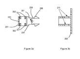
- the flanges 204 each define a hole 301 which provided for a fixing means (not shown) such as a bolt, screw or rivet to be threaded through the flanges and tightened so as to tighten and fix the collar 203 around the equipment element.
- a fixing means such as a bolt, screw or rivet
- the holes 301 and corresponding fixing means together provide clamping means for the collar 203.
- the collar 203 is provided with formations 302 on its internal surface. The formations 302 are arranged to grip the equipment element when the clamping means is in place.
- Figure 3b illustrates both of the opposing holes 211 provided by the socket 210 that each corresponds to a pair of the projections 206.
- the clip mechanism 207, 209 is arranged to be manually releasable. Pressing the pairs of projections 206 towards each other as indicated by the arrows P in figure 3c , disengages the projections 206 from their respective holes 211 and enables the separation of the two parts 201, 202 of the fixing means 107 from each other.
- the socket 210 when the first and second parts 201, 202 are engaged or clipped together, the holes 301, and thus the clamping means, is covered by the socket 210. The clamping means is thereby protected or shielded by the socket 210.
- the outlines of the equipment element 302 and the substrate 303 are shown in dotted lines.
- the fixing means is shown bonded to the substrate 303 via a suitable adhesive layer 304.
- Figure 4 shows the first part 201 in plan view so as to further illustrate the two parallel and corresponding flanges 204, arms 205 and projections 206 which are identical in function and thus provide redundancy in the fixing means 107.
- two flanges 204 and two male clip parts 207 are provided.
- each male clip part 207 comprises two sub-clip parts provided by each of the arm 205 and projection 206 pairs. Redundancy is also provided for the clamping mechanism, firstly by the bolt and holes 301 and secondly by a constriction or clamping effect provided by the socket 210 on the male clip part 207.
- the first and second parts 201, 202 or the fixing means 107 is each integrally formed.
- each part 201, 202 may be formed from the same or different material in dependence on the application of the fixing means 107.
- the selected material will take into account the biasing and resilience required for the flexing of the arms 205.
- the fixing means may thus be formed from any suitable material such as plastics, metal or synthetic composite material or any suitable combination thereof.
- the first clamping mechanism provided by the bolt & holes 301 is omitted with a clamping effect being provided solely by a constriction or clamping provided by the socket 210 on the male clip part 207. This further simplifies installation of the fixing means and reduces its part count.
- the male clip part is provided by the bracket for fixing to the substrate and the female clip part is provided by the clamp for fixing to the equipment element.
- Embodiments of the invention enable equipment elements to be fixed to a substrate quickly and securely. Furthermore, a reduced parts count relative to known fixing means reduces the cost, complexity and weight of the fixing means.
- the fixing means requires no tools for clipping and unclipping its two parts to attach or detach the equipment element from the structure.
Landscapes
- Engineering & Computer Science (AREA)
- General Engineering & Computer Science (AREA)
- Mechanical Engineering (AREA)
- Architecture (AREA)
- Civil Engineering (AREA)
- Structural Engineering (AREA)
- Aviation & Aerospace Engineering (AREA)
- Connection Of Plates (AREA)
- Piezo-Electric Or Mechanical Vibrators, Or Delay Or Filter Circuits (AREA)
- Clamps And Clips (AREA)
Abstract
Fixing means 107 for fixing an equipment element 302 to a substrate 303, said fixing means 107 comprising a first part 201 comprising supporting means 203 for supporting said equipment element 302 and a first clip part 207; and a second part 202 comprising securing means 208 for securing said fixing means 107 to said substrate 303 and a second clip part 209, said first and second clip parts being arranged to clip together so as to fix said equipment element to said substrate.
Description
- The present invention relates to fixing means for fixing an equipment element to a substrate.
- Fixing means are commonly used, for example in aircraft, for fixing pieces of equipment to supporting structures or substrates. Such fixing means commonly comprise combinations of clamps, brackets or plates connected together with bolts or other suitable means. Such fixing means can be relatively time consuming and difficult to install, particularly in complex structures. Furthermore, such fixing means commonly have a high part count, which tends to increase cost and weight.
- Embodiments of the invention provide fixing means for fixing an equipment element to a substrate, the fixing means comprising:
- a first part comprising supporting means for supporting an equipment element and a first clip part; and
- a second part comprising securing means for securing the fixing means to a substrate and a second clip part, the first and second clip parts being arranged to clip together so as to fix the equipment element to the substrate.
- The first and second clip parts may be arranged so as to be manually separable. The first and second clip parts may comprise a male part and a female part, the male part comprising two opposing clip elements, each clip element being split so as to provide redundancy for each clip element. The supporting means may comprise two flanges for securing the equipment element, each flange being integral with the first clip part. The supporting means may further comprise clamping means arranged to clamp the flanges together so as to fix the supporting means to the equipment element. The clamping means may be located so as to be covered by the first or second clip part when the clip parts are clipped together.
- Embodiments of the invention will now be described, by way of example only, with reference to the accompanying drawings in which:
-
Figure 1 is a schematic plan view of an aircraft; -
Figures 2a, 2b & 2c are isometric views of fixing means for fixing an equipment element to a substrate in the aircraft offigure 1 ; -
Figures 3a, 3b &3c are cross sectional side views of the fixing means offigure 2 ; and -
Figure 4 is a plan view of a first part of the fixing means offigure 2 . - With reference to
figure 1 , anaircraft 101 comprises a pair ofwings 102 faired into afuselage 103. Each of thewings 102 carries arespective engine 104. The aircraft comprises control andmonitoring equipment 105 for controlling and monitoring elements of theaircraft 101. The control andmonitoring equipment 105 comprisesequipment elements 106, in the form of one or more runs of pipes, cables, wires or other elements that are each secured at suitable points to a substrate in the from of the structure of theaircraft 101. In the present embodiment, theequipment elements 106 are secured to the structure of theaircraft 101 usingfixing means 107. - With reference to
figures 2a & 2b , each fixing means 107 comprises afirst part 201 and asecond part 202. The first part comprises support means 203, which, in the present embodiment, is in the form of an open collar for supporting or fixing round a tubular equipment element such as a pipe or cable (not shown). Thecollar 203 is formed into two radially extendingflanges 204 at its open ends. The distal ends of each of theflanges 204 each comprise a pair ofarms 205 that each comprises an outward facingprojection 206. Thearms 205 andprojections 206 comprised by one of theflanges 204 correspond to thearms 205 andprojections 206 of theother flange 204. In other words, thearms 205 andprojections 206 are paired across theflanges 204. Thearms 205 andprojections 206 together provide themale part 207 of a clip mechanism. Thearms 205 are resiliently biased into the position shown infigure 2a . - With reference to
figure 2b , thesecond part 202 of thefixing means 107 comprisessecuring means 208 in the form of a flanged base for fixing thesecond part 202 to the aircraft structure by any suitable means such as bolting, riveting or bonding or any combination thereof. Thebase 208 provides thefemale part 209 of the clip mechanism in the form of asocket 210. Thesocket 210 defines two opposing holes 211 (only one shown infigure 2b ) that each correspond to a pair of theprojections 206. - With reference to
figure 2c , pushing themale part 207 into thefemale part 209 causes the pairs ofprojections 206 to move towards each other as thearms 205 bend towards each other. When themale part 207 is fully located within thefemale part 209 the resilient biasing of thearms 205 moves theprojections 206 into theirrespective holes 211 so as to clip or fix the twoparts - With reference to
figure 3a , theflanges 204 each define ahole 301 which provided for a fixing means (not shown) such as a bolt, screw or rivet to be threaded through the flanges and tightened so as to tighten and fix thecollar 203 around the equipment element. In other words, theholes 301 and corresponding fixing means together provide clamping means for thecollar 203. In the present embodiment, thecollar 203 is provided withformations 302 on its internal surface. Theformations 302 are arranged to grip the equipment element when the clamping means is in place.Figure 3b illustrates both of theopposing holes 211 provided by thesocket 210 that each corresponds to a pair of theprojections 206. - With reference to
figure 3c , theclip mechanism projections 206 towards each other as indicated by the arrows P infigure 3c , disengages theprojections 206 from theirrespective holes 211 and enables the separation of the twoparts figure 3c , when the first andsecond parts holes 301, and thus the clamping means, is covered by thesocket 210. The clamping means is thereby protected or shielded by thesocket 210. Infigure 3c , the outlines of theequipment element 302 and thesubstrate 303 are shown in dotted lines. Infigure 3c , the fixing means is shown bonded to thesubstrate 303 via a suitableadhesive layer 304. -
Figure 4 shows thefirst part 201 in plan view so as to further illustrate the two parallel andcorresponding flanges 204,arms 205 andprojections 206 which are identical in function and thus provide redundancy in thefixing means 107. In other words, twoflanges 204 and twomale clip parts 207 are provided. In addition, eachmale clip part 207 comprises two sub-clip parts provided by each of thearm 205 andprojection 206 pairs. Redundancy is also provided for the clamping mechanism, firstly by the bolt andholes 301 and secondly by a constriction or clamping effect provided by thesocket 210 on themale clip part 207. - In the present embodiment, the first and
second parts fixing means 107 is each integrally formed. As will be understood by those skilled in the art, eachpart fixing means 107. The selected material will take into account the biasing and resilience required for the flexing of thearms 205. The fixing means may thus be formed from any suitable material such as plastics, metal or synthetic composite material or any suitable combination thereof. - In another embodiment, the first clamping mechanism provided by the bolt &
holes 301 is omitted with a clamping effect being provided solely by a constriction or clamping provided by thesocket 210 on themale clip part 207. This further simplifies installation of the fixing means and reduces its part count. - In a further embodiment, the male clip part is provided by the bracket for fixing to the substrate and the female clip part is provided by the clamp for fixing to the equipment element.
- Embodiments of the invention enable equipment elements to be fixed to a substrate quickly and securely. Furthermore, a reduced parts count relative to known fixing means reduces the cost, complexity and weight of the fixing means. The fixing means requires no tools for clipping and unclipping its two parts to attach or detach the equipment element from the structure.
- While the present invention has been illustrated by the description of the embodiments thereof, and while the embodiments have been described in considerable detail, it is not the intention of the applicant to restrict or in any way limit the scope of the appended claims to such detail. Additional advantages and modifications will readily appear to those skilled in the art. Therefore, the invention in its broader aspects is not limited to the specific details of the representative apparatus and method, and illustrative examples shown and described. Accordingly, departures may be made from such details without departure from the scope of applicant's general inventive concept.
Claims (6)
- Fixing means for fixing an equipment element to a substrate, said fixing means comprising:a first part comprising supporting means for supporting an equipment element and a first clip part; anda second part comprising securing means for securing said fixing means to a substrate and a second clip part, said first and second clip parts being arranged to clip together so as to fix said equipment element to said substrate.
- Fixing means according to claim 1 in which said first and second clip parts are arranged so as to be manually separable.
- Fixing means according to any preceding claim in which said first and second clip parts comprise a male part and a female part, said male part comprising two opposing clip elements, each clip element being split so as to provide redundancy for each clip element.
- Fixing means according to any preceding claim in which said supporting means comprises two flanges for securing said equipment element, each flange being integral with said first clip part.
- Fixing means according to claim 4 in which said supporting means further comprises clamping means arranged to clamp said flanges together so as to fix said supporting means to said equipment element.
- Fixing means according to claim 4 in which said clamping means is located so as to be covered by said first or second clip part when said clip parts are clipped together.
Applications Claiming Priority (1)
| Application Number | Priority Date | Filing Date | Title |
|---|---|---|---|
| GBGB1114436.7A GB201114436D0 (en) | 2011-08-22 | 2011-08-22 | Fixing means |
Publications (1)
| Publication Number | Publication Date |
|---|---|
| EP2562432A1 true EP2562432A1 (en) | 2013-02-27 |
Family
ID=44800657
Family Applications (1)
| Application Number | Title | Priority Date | Filing Date |
|---|---|---|---|
| EP12177157A Withdrawn EP2562432A1 (en) | 2011-08-22 | 2012-07-19 | Fixing means |
Country Status (3)
| Country | Link |
|---|---|
| US (1) | US9254908B2 (en) |
| EP (1) | EP2562432A1 (en) |
| GB (1) | GB201114436D0 (en) |
Cited By (4)
| Publication number | Priority date | Publication date | Assignee | Title |
|---|---|---|---|---|
| FR3033018A1 (en) * | 2015-02-24 | 2016-08-26 | Airbus Operations Sas | TUBULAR ELEMENT SUPPORT PART, IN PARTICULAR FOR AN AIRCRAFT. |
| EP3166191A1 (en) * | 2015-11-04 | 2017-05-10 | Tyco Electronics UK Limited | Clamp, base support and clamping assembly |
| EP3620370A1 (en) * | 2018-09-07 | 2020-03-11 | Airbus Operations GmbH | A support bracket for holding interior components of a vehicle |
| EP4391261A1 (en) * | 2022-12-22 | 2024-06-26 | The Boeing Company | Connector to attach wiring to a housing |
Families Citing this family (14)
| Publication number | Priority date | Publication date | Assignee | Title |
|---|---|---|---|---|
| USD742731S1 (en) * | 2013-07-19 | 2015-11-10 | Deere & Company | Stackable clamp |
| USD741696S1 (en) * | 2014-04-07 | 2015-10-27 | Andrew H. McGrath | Adjustable bracket |
| USD741697S1 (en) * | 2014-04-07 | 2015-10-27 | Andrew H. McGrath | Bracket support |
| USD741698S1 (en) * | 2014-04-07 | 2015-10-27 | Andrew H. McGrath | Bracket support |
| USD741157S1 (en) * | 2014-04-07 | 2015-10-20 | Andrew H. McGrath | Adjustable bracket |
| JP6169525B2 (en) * | 2014-04-25 | 2017-07-26 | トヨタ紡織株式会社 | Vehicle seat clip mounting structure |
| CN107112738B (en) * | 2014-12-19 | 2020-07-10 | Fi.Mo.技术股份公司 | Improved device for wall fixing of elongated bodies, especially radiating coaxial cables |
| CN105538355B (en) * | 2015-12-22 | 2017-08-15 | 任向荣 | Razor head with clipping function |
| USD822476S1 (en) | 2016-10-26 | 2018-07-10 | Hellermanntyton Corporation | Multiple option clip |
| US11384865B2 (en) * | 2017-02-21 | 2022-07-12 | Bioflex Solutions, Llc | Tube management assembly |
| US11167808B2 (en) * | 2018-01-24 | 2021-11-09 | GM Global Technology Operations LLC | Telescoping retention pin |
| JP6673399B2 (en) * | 2018-05-25 | 2020-03-25 | 株式会社オートネットワーク技術研究所 | Wiring member fixing structure |
| GB2577934B (en) * | 2018-10-12 | 2020-09-30 | Kohler Mira Ltd | Fitting assembly having clamp for securing elongate member |
| JP7354866B2 (en) * | 2020-02-12 | 2023-10-03 | 住友電装株式会社 | Support member for wire harness and wire harness |
Citations (4)
| Publication number | Priority date | Publication date | Assignee | Title |
|---|---|---|---|---|
| FR2190188A5 (en) * | 1972-06-16 | 1974-01-25 | Bratschi Cilent Gliss | |
| US6257530B1 (en) * | 1999-12-20 | 2001-07-10 | Chin Hai Tsai | Clasping device for longitudinal object |
| EP1529995A1 (en) * | 2003-11-07 | 2005-05-11 | Wermuth Enterprises | Pipe holding device |
| FR2885671A1 (en) * | 2005-05-10 | 2006-11-17 | P D C I Sarl | Clamp collar for masonry, has continuous strap with progressively deformable cells, sectile captive dowel pin integrated to collar by simple engagement of relief pin, where dowel pin is attached to collar by thin sectile strap |
Family Cites Families (5)
| Publication number | Priority date | Publication date | Assignee | Title |
|---|---|---|---|---|
| US4143577A (en) | 1977-03-28 | 1979-03-13 | All States Plastic Manufacturing Co., Inc. | Anchor base fastener |
| US4602760A (en) * | 1983-11-28 | 1986-07-29 | Tiefenbach Karolyn L | Fuel line bundle clamp |
| ATE187852T1 (en) * | 1995-06-21 | 2000-01-15 | Raymond A & Cie | TUBULAR COVERING CHANNEL FOR COVERING CABLE BUNDLES |
| US5845883A (en) * | 1997-02-12 | 1998-12-08 | Illinois Tool Works Inc. | Flexible clip assembly |
| ITPD20050248A1 (en) * | 2005-08-05 | 2007-02-06 | Moretto P A Srl | FIXING DEVICE FOR PIPELINES WITH BEARING STRUCTURES |
-
2011
- 2011-08-22 GB GBGB1114436.7A patent/GB201114436D0/en not_active Ceased
-
2012
- 2012-07-19 EP EP12177157A patent/EP2562432A1/en not_active Withdrawn
- 2012-07-25 US US13/557,352 patent/US9254908B2/en not_active Expired - Fee Related
Patent Citations (4)
| Publication number | Priority date | Publication date | Assignee | Title |
|---|---|---|---|---|
| FR2190188A5 (en) * | 1972-06-16 | 1974-01-25 | Bratschi Cilent Gliss | |
| US6257530B1 (en) * | 1999-12-20 | 2001-07-10 | Chin Hai Tsai | Clasping device for longitudinal object |
| EP1529995A1 (en) * | 2003-11-07 | 2005-05-11 | Wermuth Enterprises | Pipe holding device |
| FR2885671A1 (en) * | 2005-05-10 | 2006-11-17 | P D C I Sarl | Clamp collar for masonry, has continuous strap with progressively deformable cells, sectile captive dowel pin integrated to collar by simple engagement of relief pin, where dowel pin is attached to collar by thin sectile strap |
Cited By (8)
| Publication number | Priority date | Publication date | Assignee | Title |
|---|---|---|---|---|
| FR3033018A1 (en) * | 2015-02-24 | 2016-08-26 | Airbus Operations Sas | TUBULAR ELEMENT SUPPORT PART, IN PARTICULAR FOR AN AIRCRAFT. |
| US9562626B2 (en) | 2015-02-24 | 2017-02-07 | Airbus Operations Sas | Bracket for tubular element, in particular for aircraft |
| EP3166191A1 (en) * | 2015-11-04 | 2017-05-10 | Tyco Electronics UK Limited | Clamp, base support and clamping assembly |
| WO2017077022A1 (en) * | 2015-11-04 | 2017-05-11 | Tyco Electronics Uk Limited | Clamp, base support and clamping assembly |
| EP3620370A1 (en) * | 2018-09-07 | 2020-03-11 | Airbus Operations GmbH | A support bracket for holding interior components of a vehicle |
| US11560241B2 (en) | 2018-09-07 | 2023-01-24 | Airbus Operations Gmbh | Support bracket for holding interior components of a vehicle |
| EP4391261A1 (en) * | 2022-12-22 | 2024-06-26 | The Boeing Company | Connector to attach wiring to a housing |
| US12300407B2 (en) | 2022-12-22 | 2025-05-13 | The Boeing Company | Connector to attach wiring to a housing |
Also Published As
| Publication number | Publication date |
|---|---|
| GB201114436D0 (en) | 2011-10-05 |
| US9254908B2 (en) | 2016-02-09 |
| US20130047385A1 (en) | 2013-02-28 |
Similar Documents
| Publication | Publication Date | Title |
|---|---|---|
| US9254908B2 (en) | Fixing means | |
| EP2537745B1 (en) | Clip attachment system connecting aircraft structures to each other | |
| EP2016811B1 (en) | Adjustable mounting bracket | |
| CN107000657B (en) | Self-fastening bracket for mounting a wire harness to a support structure of a vehicle and a vehicle including the self-fastening bracket | |
| US20140060891A1 (en) | Standoff device and method of installation of harness | |
| US10731683B2 (en) | Fastening device | |
| US11906089B2 (en) | Co-molded snap-on support base, and support system and method of using the same | |
| EP1925059B1 (en) | Standoff attachment with internal nut | |
| US20140061397A1 (en) | Piggyback holdback clamp | |
| US20050224653A1 (en) | Cushioned grounding clamp | |
| US20120001025A1 (en) | Device for fastening systems for an aircraft, adapted in particular to be used in relation to a window | |
| EP2896567B1 (en) | Device mount | |
| US12275359B2 (en) | One-piece co-molded snap-on apparatus, and support system and method of using the same | |
| US9272570B2 (en) | Integral clamp hubcap for wheel system and apparatus | |
| KR100496694B1 (en) | Fasten article of wire harness | |
| CN104093998B (en) | For the method and the assembly that are installed to part on beam | |
| CN203836394U (en) | Hoop device, automobile silencer assembly and automobile | |
| CN105715872A (en) | Attaching clamp for attaching wiring harness | |
| EP2784332A1 (en) | Attachment system | |
| CN104081604A (en) | Self-indexing nut plate | |
| CN106374294B (en) | A kind of antenna for base station and the plastic fixer for connector to be auxiliarily fixed |
Legal Events
| Date | Code | Title | Description |
|---|---|---|---|
| PUAI | Public reference made under article 153(3) epc to a published international application that has entered the european phase |
Free format text: ORIGINAL CODE: 0009012 |
|
| AK | Designated contracting states |
Kind code of ref document: A1 Designated state(s): AL AT BE BG CH CY CZ DE DK EE ES FI FR GB GR HR HU IE IS IT LI LT LU LV MC MK MT NL NO PL PT RO RS SE SI SK SM TR |
|
| AX | Request for extension of the european patent |
Extension state: BA ME |
|
| STAA | Information on the status of an ep patent application or granted ep patent |
Free format text: STATUS: THE APPLICATION IS DEEMED TO BE WITHDRAWN |
|
| 18D | Application deemed to be withdrawn |
Effective date: 20130828 |