EP2562374A1 - Controller of internal combustion engine - Google Patents
Controller of internal combustion engine Download PDFInfo
- Publication number
- EP2562374A1 EP2562374A1 EP10850263A EP10850263A EP2562374A1 EP 2562374 A1 EP2562374 A1 EP 2562374A1 EP 10850263 A EP10850263 A EP 10850263A EP 10850263 A EP10850263 A EP 10850263A EP 2562374 A1 EP2562374 A1 EP 2562374A1
- Authority
- EP
- European Patent Office
- Prior art keywords
- temperature
- combustion temperature
- combustion
- engine
- catalyst device
- Prior art date
- Legal status (The legal status is an assumption and is not a legal conclusion. Google has not performed a legal analysis and makes no representation as to the accuracy of the status listed.)
- Withdrawn
Links
Images
Classifications
-
- F—MECHANICAL ENGINEERING; LIGHTING; HEATING; WEAPONS; BLASTING
- F01—MACHINES OR ENGINES IN GENERAL; ENGINE PLANTS IN GENERAL; STEAM ENGINES
- F01N—GAS-FLOW SILENCERS OR EXHAUST APPARATUS FOR MACHINES OR ENGINES IN GENERAL; GAS-FLOW SILENCERS OR EXHAUST APPARATUS FOR INTERNAL-COMBUSTION ENGINES
- F01N3/00—Exhaust or silencing apparatus having means for purifying, rendering innocuous, or otherwise treating exhaust
- F01N3/08—Exhaust or silencing apparatus having means for purifying, rendering innocuous, or otherwise treating exhaust for rendering innocuous
- F01N3/0807—Exhaust or silencing apparatus having means for purifying, rendering innocuous, or otherwise treating exhaust for rendering innocuous by using absorbents or adsorbents
- F01N3/0828—Exhaust or silencing apparatus having means for purifying, rendering innocuous, or otherwise treating exhaust for rendering innocuous by using absorbents or adsorbents characterised by the absorbed or adsorbed substances
- F01N3/0835—Hydrocarbons
-
- F—MECHANICAL ENGINEERING; LIGHTING; HEATING; WEAPONS; BLASTING
- F01—MACHINES OR ENGINES IN GENERAL; ENGINE PLANTS IN GENERAL; STEAM ENGINES
- F01N—GAS-FLOW SILENCERS OR EXHAUST APPARATUS FOR MACHINES OR ENGINES IN GENERAL; GAS-FLOW SILENCERS OR EXHAUST APPARATUS FOR INTERNAL-COMBUSTION ENGINES
- F01N13/00—Exhaust or silencing apparatus characterised by constructional features
- F01N13/009—Exhaust or silencing apparatus characterised by constructional features having two or more separate purifying devices arranged in series
- F01N13/0097—Exhaust or silencing apparatus characterised by constructional features having two or more separate purifying devices arranged in series the purifying devices are arranged in a single housing
-
- F—MECHANICAL ENGINEERING; LIGHTING; HEATING; WEAPONS; BLASTING
- F01—MACHINES OR ENGINES IN GENERAL; ENGINE PLANTS IN GENERAL; STEAM ENGINES
- F01N—GAS-FLOW SILENCERS OR EXHAUST APPARATUS FOR MACHINES OR ENGINES IN GENERAL; GAS-FLOW SILENCERS OR EXHAUST APPARATUS FOR INTERNAL-COMBUSTION ENGINES
- F01N3/00—Exhaust or silencing apparatus having means for purifying, rendering innocuous, or otherwise treating exhaust
- F01N3/08—Exhaust or silencing apparatus having means for purifying, rendering innocuous, or otherwise treating exhaust for rendering innocuous
- F01N3/10—Exhaust or silencing apparatus having means for purifying, rendering innocuous, or otherwise treating exhaust for rendering innocuous by thermal or catalytic conversion of noxious components of exhaust
- F01N3/103—Oxidation catalysts for HC and CO only
-
- F—MECHANICAL ENGINEERING; LIGHTING; HEATING; WEAPONS; BLASTING
- F02—COMBUSTION ENGINES; HOT-GAS OR COMBUSTION-PRODUCT ENGINE PLANTS
- F02D—CONTROLLING COMBUSTION ENGINES
- F02D41/00—Electrical control of supply of combustible mixture or its constituents
- F02D41/02—Circuit arrangements for generating control signals
- F02D41/021—Introducing corrections for particular conditions exterior to the engine
- F02D41/0235—Introducing corrections for particular conditions exterior to the engine in relation with the state of the exhaust gas treating apparatus
- F02D41/024—Introducing corrections for particular conditions exterior to the engine in relation with the state of the exhaust gas treating apparatus to increase temperature of the exhaust gas treating apparatus
- F02D41/0255—Introducing corrections for particular conditions exterior to the engine in relation with the state of the exhaust gas treating apparatus to increase temperature of the exhaust gas treating apparatus to accelerate the warming-up of the exhaust gas treating apparatus at engine start
-
- F—MECHANICAL ENGINEERING; LIGHTING; HEATING; WEAPONS; BLASTING
- F02—COMBUSTION ENGINES; HOT-GAS OR COMBUSTION-PRODUCT ENGINE PLANTS
- F02D—CONTROLLING COMBUSTION ENGINES
- F02D2200/00—Input parameters for engine control
- F02D2200/02—Input parameters for engine control the parameters being related to the engine
- F02D2200/08—Exhaust gas treatment apparatus parameters
- F02D2200/0802—Temperature of the exhaust gas treatment apparatus
-
- Y—GENERAL TAGGING OF NEW TECHNOLOGICAL DEVELOPMENTS; GENERAL TAGGING OF CROSS-SECTIONAL TECHNOLOGIES SPANNING OVER SEVERAL SECTIONS OF THE IPC; TECHNICAL SUBJECTS COVERED BY FORMER USPC CROSS-REFERENCE ART COLLECTIONS [XRACs] AND DIGESTS
- Y02—TECHNOLOGIES OR APPLICATIONS FOR MITIGATION OR ADAPTATION AGAINST CLIMATE CHANGE
- Y02T—CLIMATE CHANGE MITIGATION TECHNOLOGIES RELATED TO TRANSPORTATION
- Y02T10/00—Road transport of goods or passengers
- Y02T10/10—Internal combustion engine [ICE] based vehicles
- Y02T10/12—Improving ICE efficiencies
Definitions
- the present invention relates to a control system of an internal combustion engine.
- an oxidation catalyst device or a three-way catalyst device is arranged in an engine exhaust system.
- Such a catalyst device having the oxidation ability does not activate sufficiently in a low temperature condition like immediately after the starting-up of the engine. It is desired for the catalyst device to be warmed up quickly to an activation temperature in order to increase the purification ability of HC and CO.
- CO can be oxidized at a lower temperature than that at which HC can be oxidized. Therefore, first, the oxidation reaction heat of CO raises the temperature of the catalyst device. Incidentally, it is known that HC obstructs the oxidation of CO and therefore, the smaller the amount of coexisted HC, the more the oxidation rate of CO can be increased.
- a HC adsorption device is arranged immediately upstream the catalyst device (for example, refer to International Publication WO 00/27508 ). Accordingly, an amount of HC coexisting with CO in the catalyst device can be reduced by the adsorption of HC in the HC adsorption device.
- an object of the present invention is to provide a control system of an internal combustion engine, which can sufficiently increase the oxidation rate of CO in a catalyst device having the oxidation ability to realize the quick warming-up of the catalyst device.
- a control system of an internal combustion engine in which a catalyst device having the oxidation ability is arranged in the exhaust system as set forth in claim 1 of the present invention is provided, characterized in that when a temperature of the catalyst device is lower than a set temperature, the combustion temperature is made a first combustion temperature or under or is made a second combustion temperature or over, to make an amount of lower olefin in the exhaust gas smaller than that when the combustion temperature is higher than the first combustion temperature and is lower than the second combustion temperature.
- a control system of an internal combustion engine as set forth in claim 2 of the present invention is provided as the control system of an internal combustion engine as set forth in claim 1 characterized in that an engine operating area in which the combustion temperature becomes higher than the first combustion temperature and lower than the second combustion temperature is set, and when the temperature of the catalyst device is lower than the set temperature, it is prohibited that the engine operates in the engine operating area.
- a control system of an internal combustion engine as set forth in claim 3 of the present invention is provided as the control system of an internal combustion engine as set forth in claim 2 characterized in that the worse the combustion is, the more the engine operating area is expanded to the high engine load side.
- a combustion temperature is made a first combustion temperature or under or is made a second combustion temperature or over, to make an amount of lower olefin, which particularly reduces the oxidation rate of CO, in the exhaust gas smaller than that when the combustion temperature is higher than the first combustion temperature and is lower than the second combustion temperature. Therefore, the oxidation rate of CO is sufficiently increased so as to realize the quick warming-up of the catalyst device.
- the control system of an internal combustion engine as set forth in claim 2 of the present invention in the control system of an internal combustion engine as set forth in claim 1, an engine operating area in which the combustion temperature is higher than the first combustion temperature and lower than the second combustion temperature is set, and when the temperature of the catalyst device is lower than the set temperature, it is prohibited that the engine operates in the engine operating area. Therefore, the combustion temperature can be easily made the first combustion temperature or under or made the second combustion temperature or over.
- the worse the combustion becomes the more the engine operating area is expanded to the high engine load side due to the lowering of the combustion temperature. Therefore, even if the combustion deteriorates, the combustion temperature can be certainly made the first combustion temperature or under or made the second combustion temperature or over.
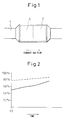
- Fig. 1 is a schematic view showing the exhaust system of an internal combustion engine which is controlled by a control system according to the present invention.
- reference numeral 1 is an exhaust passage and reference numeral 2 is a three-way catalyst device or a catalyst device having the oxidation ability with a honeycomb-shaped base material on which at least an oxidation catalyst such as platinum is carried (including a NO x storing/reducing catalyst device).
- the engine may be a spark-ignition engine or a diesel engine.
- Reference numeral 3 is a HC adsorption device arranged upstream the catalyst device 2.
- the HC adsorption device 3 comprises a honeycomb-shaped base material on which a beta zeolite or ZMS-5 is carried. The lower the temperature of the device, the larger an amount of HC that can be adsorbed becomes. Therefore, the HC adsorption device adsorbs HC in the exhaust gas in low temperatures and releases the adsorbed HC in high temperatures.
- the catalyst device 2 oxidizes HC and CO in the exhaust gas to purify them.
- the catalyst device cannot sufficiently oxidize particular HC and thus it is needed to quickly warm up the catalyst device immediately after the engine starting-up.
- the catalyst device 2 can oxidize CO at a lower temperature than that at which HC can be oxidized, and thus is warmed up by using of the oxidation reaction heat of CO at the beginning.
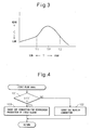
- Fig. 2 is a time-chart showing changes of the oxidation rate of CO in the catalyst device 2.
- the solid line shows a case of an exhaust gas containing about 1600 ppm of propylene C 3 H 6 (lower olefin) and CO in which the mixing of propylene is stopped at a time t0.
- the dotted line shows a case of an exhaust gas containing about 1600 ppm of decane C 10 H 22 (higher olefin) and CO in which the mixing of decane is stopped at the time t0.
- HC does not coexist, the oxidation rate of CO increases to about 100%. However, because propylene or decane coexist, each oxidation rate of CO becomes lower than 100%. When the mixing of propylene or decane is stopped, each oxidation rate of CO gradually increases.
- the lower olefin of which carbon atom number is 5 or under obstructs the oxidation of CO in the oxidation catalyst more than the higher olefin (decane) and thus drops the oxidation rate of CO so much.
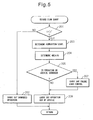
- Fig. 3 is a graph showing a relationship between a combustion temperature T (maximum combustion temperature) in the cylinder and a concentration C of lower olefin in the exhaust gas.
- the concentration of lower olefin is largest at the combustion temperature TP (for example, about 1000K).
- a combustion temperature T is this combustion temperature TP or is higher than a first combustion temperature T1 (for example, about 900K) and lower than a second combustion temperature T2 (for example, about 1100K)
- the concentration of lower olefin becomes relatively high and a larger amount of lower olefin than that when the combustion temperature T is the first combustion temperature T1 or under or the combustion temperature T is the second combustion temperature T2 or over is exhausted from the cylinder.
- the temperature of the catalyst device 2 is lower than the activation temperature of the oxidation catalyst immediately after the engine starting-up, if an operation in which the combustion temperature is higher than the first combustion temperature T1 and lower than the second combustion temperature T2 is carried out, a large amount of lower olefin is included in the exhaust gas. Even if the HC adsorption device 3 is arranged immediately upstream the catalyst device 2 and a part of the large amount of lower olefin is adsorbed in the HC adsorption device 3, a relative large amount of lower olefin obstructs the oxidation of CO in the oxidation catalyst and thus drops the oxidation rate of CO so much.
- the warming-up of the catalyst device 2 using the oxidation reaction heat of CO becomes insufficiently and thus the quick warming-up of the catalyst device cannot be realized.
- the HC adsorption device 3 is not arranged upstream the catalyst device, when the operation in which the combustion temperature is higher than the first combustion temperature T1 and lower than the second combustion temperature T2 is carried out, a large amount of lower olefin extremely drops the oxidation rate of CO so as to delay the warming-up of the catalyst device 2 more.
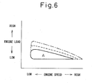
- the control system of the present embodiment controls the engine according to a first flow-chart shown in Fig. 4 to realize the quick warming-up of the catalyst device 2.
- a first flow-chart shown in Fig. 4 to realize the quick warming-up of the catalyst device 2.
- the combustion temperature T (maximum combustion temperature) in the cylinder is made the first combustion temperature T1 or under, or the second combustion temperature T2 or over.
- an exhaust valve open timing can be varied by a variable valve timing mechanism
- the combustion temperature can be made the first combustion temperature T1 or under.
- the exhaust valve open timing is delayed to bring backward the combustion finishing time in an expansion stroke
- the combustion temperature can be made the second combustion temperature T2 or over.
- an addition fuel injection into the cylinder in an expansion stroke can make the combustion temperature the second combustion temperature T2 or over.
- an amount of exhausted lower olefin which extremely drops the oxidation rate of CO in the oxidation catalyst can be decreased so that the oxidation rate of CO in the oxidation catalyst is increased so as to realize the quick warming-up of the catalyst device 2 by the oxidation reaction heat of CO.
- Fig. 5 is a second flow-chart showing a control of the engine carried out by the control system of the present embodiment, to realize the quick warming-up of the catalyst device 2.
- step 201 it is determined if the temperature (t) (measured or estimated) of the catalyst device 2 is lower than the set temperature (t') (for example, the activation temperature of the oxidation catalyst).
- the set temperature (t') for example, the activation temperature of the oxidation catalyst.
- a current combustion level is determined on the basis of fuel properties in the fuel tank (for example, cetane number and a concentration of sulfur), parts deterioration degree (for example, deterioration degrees of the fuel injector and the recirculation exhaust gas cooler), and the like.
- fuel properties in the fuel tank for example, cetane number and a concentration of sulfur
- parts deterioration degree for example, deterioration degrees of the fuel injector and the recirculation exhaust gas cooler
- the area A in which an engine operation is prohibited is shown in Fig. 6 , and is an operation area in which the combustion temperature T (maximum combustion temperature) becomes higher than the first combustion temperature T1 and lower than the second combustion temperature T2.
- the combustion temperature T maximum combustion temperature
- the area A in which an engine operation is prohibited expands to the high engine load side.
- the solid line is the area in which an engine operation is prohibited when the combustion deterioration level is low.
- the dotted line is the area in which an engine operation is prohibited when the combustion deterioration level is middle.
- the chain line is the area in which an engine operation is prohibited when the combustion deterioration level is high.
- step 205 it is determined if the current demanded operation is in the area A in which an engine operation is prohibited determined at step 204.
- the result at step 205 is negative
- step 206 the demanded operation out of the area A in which an engine operation is prohibited is carried out as it is.
- step 207 an engine load control is carried out so that the operation out of the area A in which an engine operation is prohibited can be carried out at step 206.
- the engine load control makes an alternator load increase to increase a demanded load of the engine. Therefore, the demanded engine operation can be made out of the area A in which an engine operation is prohibited.
- the engine load control can make a motor-generator operates as a generator, can make an amount of power generated by the motor-generator operating as a generator increase, or can make a torque generated by the motor-generator operating as a motor decrease, in order to increase a demanded load of the engine. Therefore, the demanded engine operation can be made out of the area A in which an engine operation is prohibited.
- the engine load control can make an amount of power generated by the motor-generator operating as the generator decrease, can make the motor-generator operate as the motor, or can make a torque generated by the motor-generator operating as the motor increase, in order to decrease a demanded load of the engine. Therefore, the demanded engine operation can be made out of the area A in which an engine operation is prohibited.
- the oxidation rate of CO in the oxidation catalyst can be increased to realize the quick warming-up of the catalyst device 2 by using of the oxidation reaction heat of CO.
- HC adsorption device 3 is arranged immediately upstream the catalyst device 2 having the oxidation ability.
- this does not limit the present invention. Even if the HC adsorption device 3 is omitted, it is advantageous for the quick warming-up of the catalyst device 2 to reduce an amount of exhausted lower olefin before finishing the warming-up of the catalyst device 2.
Landscapes
- Engineering & Computer Science (AREA)
- Chemical & Material Sciences (AREA)
- Combustion & Propulsion (AREA)
- Mechanical Engineering (AREA)
- General Engineering & Computer Science (AREA)
- Materials Engineering (AREA)
- Health & Medical Sciences (AREA)
- Chemical Kinetics & Catalysis (AREA)
- Toxicology (AREA)
- Exhaust Gas After Treatment (AREA)
- Combined Controls Of Internal Combustion Engines (AREA)
Abstract
A control system of an internal combustion engine in which a catalyst device having oxidation ability is arranged in the exhaust system, is provided. When a temperature of the catalyst device is lower than a set temperature, the combustion temperature is made a first combustion temperature or under or is made a second combustion temperature or over, to make an amount of lower olefin in the exhaust gas smaller than that when the combustion temperature is higher than the first combustion temperature and is lower than the second combustion temperature. Therefore, an amount of lower olefin which reduces the oxidation rate of CO in the catalyst device is decreased so as to realize the quick warming-up of the catalyst device by using of the oxidation reaction heat of CO.
Description
- The present invention relates to a control system of an internal combustion engine.
- To purify HC and CO in exhaust gas, an oxidation catalyst device or a three-way catalyst device is arranged in an engine exhaust system. Such a catalyst device having the oxidation ability does not activate sufficiently in a low temperature condition like immediately after the starting-up of the engine. It is desired for the catalyst device to be warmed up quickly to an activation temperature in order to increase the purification ability of HC and CO.
- In the catalyst device having the oxidation ability, CO can be oxidized at a lower temperature than that at which HC can be oxidized. Therefore, first, the oxidation reaction heat of CO raises the temperature of the catalyst device. Incidentally, it is known that HC obstructs the oxidation of CO and therefore, the smaller the amount of coexisted HC, the more the oxidation rate of CO can be increased.
- It has been suggested that a HC adsorption device is arranged immediately upstream the catalyst device (for example, refer to International Publication
WO 00/27508 - Even if the HC adsorption device is arranged immediately upstream the catalyst device as mentioned above, in an engine operating state, the oxidation rate of CO cannot be increased very much and the quick warming-up of the catalyst device cannot be realized.
- Accordingly, an object of the present invention is to provide a control system of an internal combustion engine, which can sufficiently increase the oxidation rate of CO in a catalyst device having the oxidation ability to realize the quick warming-up of the catalyst device.
- A control system of an internal combustion engine in which a catalyst device having the oxidation ability is arranged in the exhaust system as set forth in
claim 1 of the present invention is provided, characterized in that when a temperature of the catalyst device is lower than a set temperature, the combustion temperature is made a first combustion temperature or under or is made a second combustion temperature or over, to make an amount of lower olefin in the exhaust gas smaller than that when the combustion temperature is higher than the first combustion temperature and is lower than the second combustion temperature. - A control system of an internal combustion engine as set forth in
claim 2 of the present invention is provided as the control system of an internal combustion engine as set forth inclaim 1 characterized in that an engine operating area in which the combustion temperature becomes higher than the first combustion temperature and lower than the second combustion temperature is set, and when the temperature of the catalyst device is lower than the set temperature, it is prohibited that the engine operates in the engine operating area. - A control system of an internal combustion engine as set forth in
claim 3 of the present invention is provided as the control system of an internal combustion engine as set forth inclaim 2 characterized in that the worse the combustion is, the more the engine operating area is expanded to the high engine load side. - According to the control system of an internal combustion engine as set forth in
claim 1 of the present invention, when a temperature of the catalyst device having the oxidation ability, which is arranged in the engine exhaust system, is lower than a set temperature, a combustion temperature is made a first combustion temperature or under or is made a second combustion temperature or over, to make an amount of lower olefin, which particularly reduces the oxidation rate of CO, in the exhaust gas smaller than that when the combustion temperature is higher than the first combustion temperature and is lower than the second combustion temperature. Therefore, the oxidation rate of CO is sufficiently increased so as to realize the quick warming-up of the catalyst device. - According to the control system of an internal combustion engine as set forth in
claim 2 of the present invention, in the control system of an internal combustion engine as set forth inclaim 1, an engine operating area in which the combustion temperature is higher than the first combustion temperature and lower than the second combustion temperature is set, and when the temperature of the catalyst device is lower than the set temperature, it is prohibited that the engine operates in the engine operating area. Therefore, the combustion temperature can be easily made the first combustion temperature or under or made the second combustion temperature or over. - According to the control system of an internal combustion engine as set forth in
claim 3 of the present invention, in the control system of an internal combustion engine as set forth inclaim 2, the worse the combustion becomes, the more the engine operating area is expanded to the high engine load side due to the lowering of the combustion temperature. Therefore, even if the combustion deteriorates, the combustion temperature can be certainly made the first combustion temperature or under or made the second combustion temperature or over. -
-
Fig. 1 is a schematic view showing the exhaust system of an internal combustion engine which is controlled by a control system according to the present invention. -
Fig. 2 is a time-chart showing changes of the oxidation rate of CO in an oxidation catalyst device. -
Fig. 3 is a graph showing a relationship between a combustion temperature and a concentration of lower olefin in the exhaust gas. -
Fig. 4 is a first flow-chart showing a control of the engine by the control system according to the present invention. -
Fig. 5 is a second flow-chart showing a control of the engine by the control system according to the present invention. -
Fig. 6 is a map showing an area in which the engine operation is prohibited in the second flow-chart. -
Fig. 1 is a schematic view showing the exhaust system of an internal combustion engine which is controlled by a control system according to the present invention. In the figure,reference numeral 1 is an exhaust passage andreference numeral 2 is a three-way catalyst device or a catalyst device having the oxidation ability with a honeycomb-shaped base material on which at least an oxidation catalyst such as platinum is carried (including a NOx storing/reducing catalyst device). The engine may be a spark-ignition engine or a diesel engine. -
Reference numeral 3 is a HC adsorption device arranged upstream thecatalyst device 2. TheHC adsorption device 3 comprises a honeycomb-shaped base material on which a beta zeolite or ZMS-5 is carried. The lower the temperature of the device, the larger an amount of HC that can be adsorbed becomes. Therefore, the HC adsorption device adsorbs HC in the exhaust gas in low temperatures and releases the adsorbed HC in high temperatures. - The
catalyst device 2 oxidizes HC and CO in the exhaust gas to purify them. However, when the oxidation catalyst has not become an activation temperature, the catalyst device cannot sufficiently oxidize particular HC and thus it is needed to quickly warm up the catalyst device immediately after the engine starting-up. Thecatalyst device 2 can oxidize CO at a lower temperature than that at which HC can be oxidized, and thus is warmed up by using of the oxidation reaction heat of CO at the beginning. -
Fig. 2 is a time-chart showing changes of the oxidation rate of CO in thecatalyst device 2. The solid line shows a case of an exhaust gas containing about 1600 ppm of propylene C3H6 (lower olefin) and CO in which the mixing of propylene is stopped at a time t0. The dotted line shows a case of an exhaust gas containing about 1600 ppm of decane C10H22 (higher olefin) and CO in which the mixing of decane is stopped at the time t0. If HC does not coexist, the oxidation rate of CO increases to about 100%. However, because propylene or decane coexist, each oxidation rate of CO becomes lower than 100%. When the mixing of propylene or decane is stopped, each oxidation rate of CO gradually increases. - As shown in
Fig. 2 , the lower olefin of which carbon atom number is 5 or under (for example, ethylene or propylene) obstructs the oxidation of CO in the oxidation catalyst more than the higher olefin (decane) and thus drops the oxidation rate of CO so much. -
Fig. 3 is a graph showing a relationship between a combustion temperature T (maximum combustion temperature) in the cylinder and a concentration C of lower olefin in the exhaust gas. The concentration of lower olefin is largest at the combustion temperature TP (for example, about 1000K). When a combustion temperature T is this combustion temperature TP or is higher than a first combustion temperature T1 (for example, about 900K) and lower than a second combustion temperature T2 (for example, about 1100K), the concentration of lower olefin becomes relatively high and a larger amount of lower olefin than that when the combustion temperature T is the first combustion temperature T1 or under or the combustion temperature T is the second combustion temperature T2 or over is exhausted from the cylinder. - Accordingly, when the temperature of the
catalyst device 2 is lower than the activation temperature of the oxidation catalyst immediately after the engine starting-up, if an operation in which the combustion temperature is higher than the first combustion temperature T1 and lower than the second combustion temperature T2 is carried out, a large amount of lower olefin is included in the exhaust gas. Even if theHC adsorption device 3 is arranged immediately upstream thecatalyst device 2 and a part of the large amount of lower olefin is adsorbed in theHC adsorption device 3, a relative large amount of lower olefin obstructs the oxidation of CO in the oxidation catalyst and thus drops the oxidation rate of CO so much. - Therefore, the warming-up of the
catalyst device 2 using the oxidation reaction heat of CO becomes insufficiently and thus the quick warming-up of the catalyst device cannot be realized. If theHC adsorption device 3 is not arranged upstream the catalyst device, when the operation in which the combustion temperature is higher than the first combustion temperature T1 and lower than the second combustion temperature T2 is carried out, a large amount of lower olefin extremely drops the oxidation rate of CO so as to delay the warming-up of thecatalyst device 2 more. - The control system of the present embodiment controls the engine according to a first flow-chart shown in
Fig. 4 to realize the quick warming-up of thecatalyst device 2. First, atstep 101, it is determined if the temperature (t) (measured or estimated) of thecatalyst device 2 is lower than a set temperature (t') (for example, the activation temperature of the oxidation catalyst). When the result atstep 101 is negative, the warming-up of thecatalyst device 2 has finished, and therefore atstep 102, regular combustion is carried out. - On the other hand, when the result at
step 101 is positive, the warming-up of thecatalyst device 2 has not finished, and therefore atstep 103, combustion for restraining the production of lower olefin is carried out. In the combustion for restraining the production of lower olefin, the combustion temperature T (maximum combustion temperature) in the cylinder is made the first combustion temperature T1 or under, or the second combustion temperature T2 or over. - For example, when an exhaust valve open timing can be varied by a variable valve timing mechanism, if the exhaust valve open timing is advanced to bring forward the combustion finishing time in an expansion stroke, the combustion temperature can be made the first combustion temperature T1 or under. On the other hand, if the exhaust valve open timing is delayed to bring backward the combustion finishing time in an expansion stroke, the combustion temperature can be made the second combustion temperature T2 or over. Further, an addition fuel injection into the cylinder in an expansion stroke can make the combustion temperature the second combustion temperature T2 or over.
- When the maximum combustion temperature T is made the second combustion temperature T2 or over, there is a period in which the temperature in the cylinder is higher than the first combustion temperature T1 and is lower than the second combustion temperature T2. However, this period is very short and may not contribute to the production of lower olefin.
- Thus, according to the combustion for restraining the production of lower olefin, an amount of exhausted lower olefin which extremely drops the oxidation rate of CO in the oxidation catalyst can be decreased so that the oxidation rate of CO in the oxidation catalyst is increased so as to realize the quick warming-up of the
catalyst device 2 by the oxidation reaction heat of CO. -
Fig. 5 is a second flow-chart showing a control of the engine carried out by the control system of the present embodiment, to realize the quick warming-up of thecatalyst device 2. First, atstep 201, it is determined if the temperature (t) (measured or estimated) of thecatalyst device 2 is lower than the set temperature (t') (for example, the activation temperature of the oxidation catalyst). When the result atstep 201 is negative, the warming-up of thecatalyst device 2 has been finished and therefore atstep 202, a demanded operation is carried out as it is. - On the other hand, when the result at
step 201 is positive, atstep 203, a current combustion level is determined on the basis of fuel properties in the fuel tank (for example, cetane number and a concentration of sulfur), parts deterioration degree (for example, deterioration degrees of the fuel injector and the recirculation exhaust gas cooler), and the like. Next, atstep 204, an area A in which an engine operation is prohibited is determined on the basis of the current combustion level. - The area A in which an engine operation is prohibited is shown in
Fig. 6 , and is an operation area in which the combustion temperature T (maximum combustion temperature) becomes higher than the first combustion temperature T1 and lower than the second combustion temperature T2. The more the combustion level deteriorates, the higher the engine load in which the combustion temperature is low becomes. Therefore, the area A in which an engine operation is prohibited expands to the high engine load side. Namely, the solid line is the area in which an engine operation is prohibited when the combustion deterioration level is low. The dotted line is the area in which an engine operation is prohibited when the combustion deterioration level is middle. The chain line is the area in which an engine operation is prohibited when the combustion deterioration level is high. - Next, at
step 205, it is determined if the current demanded operation is in the area A in which an engine operation is prohibited determined atstep 204. When the result atstep 205 is negative, atstep 206, the demanded operation out of the area A in which an engine operation is prohibited is carried out as it is. - On the other hand, when the result at
step 205 is positive, atstep 207, an engine load control is carried out so that the operation out of the area A in which an engine operation is prohibited can be carried out atstep 206. For example, the engine load control makes an alternator load increase to increase a demanded load of the engine. Therefore, the demanded engine operation can be made out of the area A in which an engine operation is prohibited. - Further, for example, when the engine is used in a hybrid vehicle, the engine load control can make a motor-generator operates as a generator, can make an amount of power generated by the motor-generator operating as a generator increase, or can make a torque generated by the motor-generator operating as a motor decrease, in order to increase a demanded load of the engine. Therefore, the demanded engine operation can be made out of the area A in which an engine operation is prohibited.
- Further, the engine load control can make an amount of power generated by the motor-generator operating as the generator decrease, can make the motor-generator operate as the motor, or can make a torque generated by the motor-generator operating as the motor increase, in order to decrease a demanded load of the engine. Therefore, the demanded engine operation can be made out of the area A in which an engine operation is prohibited.
- Thus, when the warming-up of the
catalyst device 2 has not been finished, an operation exhausting a large amount of lower olefin is prohibited so that an amount of exhausted lower olefin which makes the oxidation rate of CO in the oxidation catalyst extremely decrease can be reduced. Therefore, the oxidation rate of CO in the oxidation catalyst can be increased to realize the quick warming-up of thecatalyst device 2 by using of the oxidation reaction heat of CO. - In the present embodiment,
HC adsorption device 3 is arranged immediately upstream thecatalyst device 2 having the oxidation ability. However, this does not limit the present invention. Even if theHC adsorption device 3 is omitted, it is advantageous for the quick warming-up of thecatalyst device 2 to reduce an amount of exhausted lower olefin before finishing the warming-up of thecatalyst device 2. -
- 1:
- exhaust passage
- 2:
- catalyst device
- 3:
- HC adsorption device
Claims (3)
- A control system of an internal combustion engine in which a catalyst device having the oxidation ability is arranged in the exhaust system, characterized in that when a temperature of said catalyst device is lower than a set temperature, the combustion temperature is made a first combustion temperature or under or is made a second combustion temperature or over, to make an amount of lower olefin in the exhaust gas smaller than that when the combustion temperature is higher than said first combustion temperature and is lower than said second combustion temperature.
- A control system of an internal combustion engine according to claim 1, characterized in that an engine operating area in which the combustion temperature becomes higher than said first combustion temperature and lower than said second combustion temperature is set, and when the temperature of said catalyst device is lower than the set temperature, it is prohibited that the engine operates in said engine operating area.
- A control system of an internal combustion engine according to claim 2, characterized in that the worse the combustion becomes, the more said engine operating area is expanded to the high engine load side.
Applications Claiming Priority (1)
| Application Number | Priority Date | Filing Date | Title |
|---|---|---|---|
| PCT/JP2010/057639 WO2011132322A1 (en) | 2010-04-22 | 2010-04-22 | Controller of internal combustion engine |
Publications (1)
| Publication Number | Publication Date |
|---|---|
| EP2562374A1 true EP2562374A1 (en) | 2013-02-27 |
Family
ID=44833874
Family Applications (1)
| Application Number | Title | Priority Date | Filing Date |
|---|---|---|---|
| EP10850263A Withdrawn EP2562374A1 (en) | 2010-04-22 | 2010-04-22 | Controller of internal combustion engine |
Country Status (5)
| Country | Link |
|---|---|
| US (1) | US20130034469A1 (en) |
| EP (1) | EP2562374A1 (en) |
| JP (1) | JPWO2011132322A1 (en) |
| CN (1) | CN102791980A (en) |
| WO (1) | WO2011132322A1 (en) |
Cited By (1)
| Publication number | Priority date | Publication date | Assignee | Title |
|---|---|---|---|---|
| EP3527798A4 (en) * | 2016-10-13 | 2020-03-18 | Kawasaki Jukogyo Kabushiki Kaisha | GAS ENGINE SYSTEM |
Families Citing this family (2)
| Publication number | Priority date | Publication date | Assignee | Title |
|---|---|---|---|---|
| CA2866513A1 (en) * | 2014-10-02 | 2016-04-02 | Fluid Energy Group Ltd. | Synthetic acid compositions alternatives to conventional acids in the oil and gas industry |
| US9739190B2 (en) * | 2015-11-12 | 2017-08-22 | GM Global Technology Operations LLC | Method and apparatus to control reductant injection into an exhaust gas feedstream |
Family Cites Families (12)
| Publication number | Priority date | Publication date | Assignee | Title |
|---|---|---|---|---|
| JPH08232743A (en) * | 1995-02-27 | 1996-09-10 | Isuzu Motors Ltd | NOx reduction device in exhaust gas |
| GB9511421D0 (en) * | 1995-06-06 | 1995-08-02 | Johnson Matthey Plc | Improvements in emissions control |
| US6029623A (en) * | 1997-12-10 | 2000-02-29 | Exxon Research And Engineering Co. | NOx reductant generation in a compression-ignition engine by hydrocarbon injection during the expansion stroke |
| JPH11324829A (en) * | 1998-05-18 | 1999-11-26 | Nissan Motor Co Ltd | Control device for internal combustion engine |
| WO2000027508A1 (en) | 1998-11-05 | 2000-05-18 | Toyota Jidosha Kabushiki Kaisha | Method and system for purifying exhaust gases and exhaust gas purification catalyst for use therein and method for preparation thereof |
| JP2001159362A (en) * | 1999-12-03 | 2001-06-12 | Mazda Motor Corp | Engine exhaust purification device |
| US6837909B2 (en) * | 2000-04-10 | 2005-01-04 | Nippon Oil Corporation | Fuel for use in a fuel cell system |
| JP3716738B2 (en) * | 2000-11-06 | 2005-11-16 | 日産自動車株式会社 | Exhaust gas purification device for internal combustion engine |
| GB0029115D0 (en) * | 2000-11-29 | 2001-01-10 | Sgs Thomson Microelectronics | Assembling an object code module |
| US7877986B2 (en) * | 2007-05-04 | 2011-02-01 | GM Global Technology Operations LLC | Method and apparatus for generating a reductant in an exhaust gas of a compression-ignition engine |
| US8056320B2 (en) * | 2008-05-30 | 2011-11-15 | GM Global Technology Operations LLC | Cold-start control systems for internal combustion engines |
| EP2508725A1 (en) * | 2009-12-01 | 2012-10-10 | Toyota Jidosha Kabushiki Kaisha | Exhaust purification device for internal combustion engine |
-
2010
- 2010-04-22 US US13/641,993 patent/US20130034469A1/en not_active Abandoned
- 2010-04-22 CN CN2010800653879A patent/CN102791980A/en active Pending
- 2010-04-22 EP EP10850263A patent/EP2562374A1/en not_active Withdrawn
- 2010-04-22 JP JP2011521792A patent/JPWO2011132322A1/en active Pending
- 2010-04-22 WO PCT/JP2010/057639 patent/WO2011132322A1/en not_active Ceased
Non-Patent Citations (1)
| Title |
|---|
| See references of WO2011132322A1 * |
Cited By (1)
| Publication number | Priority date | Publication date | Assignee | Title |
|---|---|---|---|---|
| EP3527798A4 (en) * | 2016-10-13 | 2020-03-18 | Kawasaki Jukogyo Kabushiki Kaisha | GAS ENGINE SYSTEM |
Also Published As
| Publication number | Publication date |
|---|---|
| US20130034469A1 (en) | 2013-02-07 |
| WO2011132322A1 (en) | 2011-10-27 |
| JPWO2011132322A1 (en) | 2013-07-18 |
| CN102791980A (en) | 2012-11-21 |
Similar Documents
| Publication | Publication Date | Title |
|---|---|---|
| US9180408B2 (en) | Fuel efficient ammonia generation strategy for lean-burn engines utilizing passive NH3-SCR for the control of NOx | |
| CN102084096B (en) | Passive Ammonia Selective Catalytic Reduction for NOx Control in Internal Combustion Engines | |
| CN101825009B (en) | Method for exhaust aftertreatment in an internal combustion engine | |
| EP2406473B1 (en) | Operating method for an exhaust aftertreatment system and exhaust aftertreatment system | |
| CN101605683B (en) | Catalyst temperature raising device for hybrid vehicle | |
| US8216521B2 (en) | Method and apparatus for ammonia formation in a catalytic converter | |
| US11073056B2 (en) | Methods and systems for exhaust emission control | |
| CN108625960B (en) | Method and system for a diesel oxidation catalyst | |
| US20130340408A1 (en) | Technique to diagnose and control ammonia generation from a twc for passive ammonia scr operation | |
| US9120057B2 (en) | Method for operating exhaust gas purification systems | |
| CN102084097A (en) | Passive ammonia-selective catalytic reduction for NOx control in internal combustion engines | |
| GB2449163A (en) | Method for operating an engine system | |
| JP2018127990A (en) | Abnormality diagnostic device for exhaust emission control device for internal combustion engine | |
| US9151196B2 (en) | Ducting system for feeding air and exhaust gases to an internal combustion engine and for discharging the exhaust gases produced by the internal combustion engine from the internal combustion engine | |
| US20100139251A1 (en) | Method and apparatus for controlling exhaust emissions in a spark-ignition direct-injection engine | |
| CN111691951A (en) | Method and system for exhaust emission control | |
| JP2008025507A (en) | Exhaust gas purification system for internal combustion engine | |
| US9512793B2 (en) | Combustion driven ammonia generation strategies for passive ammonia SCR system | |
| US8201392B2 (en) | Emission reduction system for turbo charged engine | |
| US20120011831A1 (en) | Method for Managing Temperatures in an Exhaust System of a Motor Vehicle | |
| EP2562374A1 (en) | Controller of internal combustion engine | |
| JPH11132035A (en) | Exhaust gas purification device for internal combustion engine | |
| EP2857647A1 (en) | Exhaust gas purification device for internal combustion engine | |
| WO2014087952A1 (en) | Exhaust purification system of internal combustion engine | |
| US11674423B2 (en) | Lean burn internal combustion engine exhaust gas control |
Legal Events
| Date | Code | Title | Description |
|---|---|---|---|
| PUAI | Public reference made under article 153(3) epc to a published international application that has entered the european phase |
Free format text: ORIGINAL CODE: 0009012 |
|
| 17P | Request for examination filed |
Effective date: 20121107 |
|
| AK | Designated contracting states |
Kind code of ref document: A1 Designated state(s): AT BE BG CH CY CZ DE DK EE ES FI FR GB GR HR HU IE IS IT LI LT LU LV MC MK MT NL NO PL PT RO SE SI SK SM TR |
|
| STAA | Information on the status of an ep patent application or granted ep patent |
Free format text: STATUS: THE APPLICATION HAS BEEN WITHDRAWN |
|
| 18W | Application withdrawn |
Effective date: 20130423 |