EP2562365A2 - Blade outer air seal with multi impingement plate assembly - Google Patents
Blade outer air seal with multi impingement plate assembly Download PDFInfo
- Publication number
- EP2562365A2 EP2562365A2 EP12181419A EP12181419A EP2562365A2 EP 2562365 A2 EP2562365 A2 EP 2562365A2 EP 12181419 A EP12181419 A EP 12181419A EP 12181419 A EP12181419 A EP 12181419A EP 2562365 A2 EP2562365 A2 EP 2562365A2
- Authority
- EP
- European Patent Office
- Prior art keywords
- impingement plate
- cavity
- impingement
- assembly
- plate
- Prior art date
- Legal status (The legal status is an assumption and is not a legal conclusion. Google has not performed a legal analysis and makes no representation as to the accuracy of the status listed.)
- Granted
Links
Images


Classifications
-
- F—MECHANICAL ENGINEERING; LIGHTING; HEATING; WEAPONS; BLASTING
- F01—MACHINES OR ENGINES IN GENERAL; ENGINE PLANTS IN GENERAL; STEAM ENGINES
- F01D—NON-POSITIVE DISPLACEMENT MACHINES OR ENGINES, e.g. STEAM TURBINES
- F01D11/00—Preventing or minimising internal leakage of working-fluid, e.g. between stages
- F01D11/08—Preventing or minimising internal leakage of working-fluid, e.g. between stages for sealing space between rotor blade tips and stator
- F01D11/14—Adjusting or regulating tip-clearance, i.e. distance between rotor-blade tips and stator casing
- F01D11/20—Actively adjusting tip-clearance
- F01D11/24—Actively adjusting tip-clearance by selectively cooling-heating stator or rotor components
-
- F—MECHANICAL ENGINEERING; LIGHTING; HEATING; WEAPONS; BLASTING
- F01—MACHINES OR ENGINES IN GENERAL; ENGINE PLANTS IN GENERAL; STEAM ENGINES
- F01D—NON-POSITIVE DISPLACEMENT MACHINES OR ENGINES, e.g. STEAM TURBINES
- F01D11/00—Preventing or minimising internal leakage of working-fluid, e.g. between stages
- F01D11/08—Preventing or minimising internal leakage of working-fluid, e.g. between stages for sealing space between rotor blade tips and stator
-
- F—MECHANICAL ENGINEERING; LIGHTING; HEATING; WEAPONS; BLASTING
- F05—INDEXING SCHEMES RELATING TO ENGINES OR PUMPS IN VARIOUS SUBCLASSES OF CLASSES F01-F04
- F05D—INDEXING SCHEME FOR ASPECTS RELATING TO NON-POSITIVE-DISPLACEMENT MACHINES OR ENGINES, GAS-TURBINES OR JET-PROPULSION PLANTS
- F05D2230/00—Manufacture
- F05D2230/80—Repairing, retrofitting or upgrading methods
-
- F—MECHANICAL ENGINEERING; LIGHTING; HEATING; WEAPONS; BLASTING
- F05—INDEXING SCHEMES RELATING TO ENGINES OR PUMPS IN VARIOUS SUBCLASSES OF CLASSES F01-F04
- F05D—INDEXING SCHEME FOR ASPECTS RELATING TO NON-POSITIVE-DISPLACEMENT MACHINES OR ENGINES, GAS-TURBINES OR JET-PROPULSION PLANTS
- F05D2240/00—Components
- F05D2240/10—Stators
- F05D2240/11—Shroud seal segments
-
- F—MECHANICAL ENGINEERING; LIGHTING; HEATING; WEAPONS; BLASTING
- F05—INDEXING SCHEMES RELATING TO ENGINES OR PUMPS IN VARIOUS SUBCLASSES OF CLASSES F01-F04
- F05D—INDEXING SCHEME FOR ASPECTS RELATING TO NON-POSITIVE-DISPLACEMENT MACHINES OR ENGINES, GAS-TURBINES OR JET-PROPULSION PLANTS
- F05D2260/00—Function
- F05D2260/20—Heat transfer, e.g. cooling
- F05D2260/201—Heat transfer, e.g. cooling by impingement of a fluid
-
- F—MECHANICAL ENGINEERING; LIGHTING; HEATING; WEAPONS; BLASTING
- F05—INDEXING SCHEMES RELATING TO ENGINES OR PUMPS IN VARIOUS SUBCLASSES OF CLASSES F01-F04
- F05D—INDEXING SCHEME FOR ASPECTS RELATING TO NON-POSITIVE-DISPLACEMENT MACHINES OR ENGINES, GAS-TURBINES OR JET-PROPULSION PLANTS
- F05D2260/00—Function
- F05D2260/20—Heat transfer, e.g. cooling
- F05D2260/205—Cooling fluid recirculation, i.e. after cooling one or more components is the cooling fluid recovered and used elsewhere for other purposes
-
- Y—GENERAL TAGGING OF NEW TECHNOLOGICAL DEVELOPMENTS; GENERAL TAGGING OF CROSS-SECTIONAL TECHNOLOGIES SPANNING OVER SEVERAL SECTIONS OF THE IPC; TECHNICAL SUBJECTS COVERED BY FORMER USPC CROSS-REFERENCE ART COLLECTIONS [XRACs] AND DIGESTS
- Y02—TECHNOLOGIES OR APPLICATIONS FOR MITIGATION OR ADAPTATION AGAINST CLIMATE CHANGE
- Y02T—CLIMATE CHANGE MITIGATION TECHNOLOGIES RELATED TO TRANSPORTATION
- Y02T50/00—Aeronautics or air transport
- Y02T50/60—Efficient propulsion technologies, e.g. for aircraft
Definitions
- the present application relates to a blade outer air seal (BOAS) and more particularly to a multi impingement plate assembly therefor.
- BOAS blade outer air seal
- Gas turbine engines generally include fan, compressor, combustor and turbine sections along an engine axis of rotation.
- the fan, compressor, and turbine sections each include a series of stator and rotor blade assemblies.
- a rotor and an axially adjacent array of stator assemblies may be referred to as a stage.
- Each stator vane assembly increases efficiency through the direction of core gas flow into or out of the rotor assemblies.
- An outer case includes a blade outer air seal (BOAS) to provide an outer radial flow path boundary for the core gas flow.
- BOAS blade outer air seal
- a multiple of BOAS segments are typically provided to accommodate thermal and dynamic variation typical in a high pressure turbine (HPT) section of the gas turbine engine.
- the BOAS segments are subjected to relatively high temperatures and receive a secondary cooling airflow for temperature control.
- a multi impingement plate assembly for a Blade Outer Air Seal (BOAS) includes a first impingement plate which defines a multiple of first impingement plate holes and a second impingement plate attached to the first impingement plate.
- the second impingement plate includes a platform section spaced away from the multiple of first impingement plate holes to define a plate cavity.
- a blade outer air seal assembly includes a body that defines a first cavity separated from a second cavity by a circumferential rib.
- a multi impingement plate assembly defines a plate cavity, the multi impingement plate assembly circulates a secondary cooling air flow between the first cavity and the second cavity through the plate cavity.
- a method of communicating a secondary cooling airflow within a gas turbine engine includes segregating a first cavity from a second cavity by a circumferential rib and communicating the secondary cooling airflow between the first cavity and the second cavity through a plate cavity of a multi impingement plate assembly.
- FIG. 1 schematically illustrates a gas turbine engine 20, illustrated partially herein as a High Pressure Turbine (HPT) section 22 disposed along a common engine longitudinal axis A.
- the engine 20 includes a Blade Outer Air Seal (BOAS) assembly 24 to provide an outer core gas path seal for the turbine section 22.
- BOAS Blade Outer Air Seal
- FIG. 1 schematically illustrates a gas turbine engine 20, illustrated partially herein as a High Pressure Turbine (HPT) section 22 disposed along a common engine longitudinal axis A.
- the engine 20 includes a Blade Outer Air Seal (BOAS) assembly 24 to provide an outer core gas path seal for the turbine section 22.
- BOAS Blade Outer Air Seal
- the BOAS segment may find beneficial use in many industries including aerospace, industrial, electricity generation, naval propulsion, pumping sets for gas and oil transmission, aircraft propulsion, vehicle engines, and stationary power plants.
- the HPT section 22 generally includes a rotor assembly 26 disposed between forward and aft stationary vane assemblies 28, 30 (illustrated schematically). Outer vane supports 28A, 30A attach the respective vane assemblies to an engine case 32 (illustrated schematically).
- the rotor assembly 26 generally includes a multiple of airfoils 34 circumferentially disposed around a disk 36. The distal end of each airfoil 34 may be referred to as an airfoil tip 34T which rides adjacent to the BOAS assembly 24.
- the BOAS assembly 24 is disposed in an annulus radially between the engine case 32 and the airfoil tips 34T.
- the BOAS assembly 24 generally includes a blade outer air seal (BOAS) support 38 and a multiple of blade outer air seal (BOAS) segments 40 mountable thereto (also see Figure 2 ).
- the BOAS support 38 is mounted within the engine case 32 to define forward and aft flanges 42, 44 to receive the BOAS segments 40.
- the forward flanges 42 and the aft flanges 44 may be circumferentially segmented to receive the BOAS segments 40 in a circumferentially rotated and locked arrangement as generally understood.
- Each BOAS segment 40 includes a body 46 which defines a forward interface 48 and an aft interface 50.
- the forward interface 48 and the aft interface 50 respectively engage the flanges 42, 44 to secure each BOAS segment 40 thereto. It should also be understood that various interfaces and BOAS assemblies may alternatively be provided.
- each BOAS segment 40 includes at least two cavities 52A, 52B to receive a secondary cooling airflow S.
- the cavity 52A is axially forward of cavity 52B but separated therefrom by a circumferential rib 56. That is, the circumferential rib 56 essentially surrounds the engine longitudinal axis A.
- Each cavity 52A, 52B may be formed through, for example, an investment casting process then closed by a multi impingement plate assembly 54 ( Figure 3 ).
- a multiple of edge holes 80 and a multiple of film holes 82 provide flow communication for the secondary cooling air S from the cavities 52A, 52B into the core gaspath flow C.
- the multiple of edge holes 80 are arranged generally circumferentially and the multiple of film holes 82 are arranged generally radially with respect to the engine axis A. It should be understood that various numbers, sizes, orientations and arrangements may be provided and that the holes 80, 82 are illustrated somewhat schematically.
- the multi impingement plate assembly 54 generally includes a first impingement plate 60 and a second impingement plate 62, however, any number of plates or plate sections may be utilized.
- the first impingement plate 60 and the second impingement plate 62 may be welded together as a unit then welded to the body 46 ( Figure 3 ). That is, the multi impingement plate assembly 54 facilitates retrofit for single impingement plate BOAS designs.
- the first impingement plate 60 extends between a forward ledge 64, and an aft ledge 66 over the circumferential rib 56.
- the first impingement plate 60 generally includes a window 67 over the forward cavity 52A and a multiple of impingement holes 68 over the aft cavity 52B ( Figure 4 ).
- the first impingement plate 60 extends from the circumferential rib 56 to the aft ledge 66 to cover the aft cavity 52B.
- the second impingement plate 62 extends between the forward ledge 64 and the aft ledge 66 over the first impingement plate 60.
- the second impingement plate 62 includes a platform section 70 which is displaced from a plane P2 which defines a base section 72. Plane P2 is parallel to plane P1 which is defined by the first impingement plate 60.
- the platform section 70 is imperforate while the base section 72 includes a multiple of impingement holes 74.
- the second impingement plate 62 may be welded along a periphery of the first impingement plate 60 to form a spaced relationship therebetween over the multiple of impingement holes 68.
- At least one passage 76 extends between the platform section 70 and the base section 72 beyond the circumferential rib 56 (best seen in Figure 3 ). That is, the at least one passage 76 provides a transition between the platform section 70 and the base section 72 for communication of the secondary cooling air S from the forward cavity 52A to a plate cavity 78 between the platform section 70 and the first impingement plate 60.
- the passage 76 may include a set of passages 76 which may be generally U-shaped and is displaced from the plane P2 which includes the base section 72
- the at least one passage 76 provides a fluid communication path S 1 ( Figure 4 ) for the secondary cooling air S which enters through the multiple of second impingement holes 74 into the forward cavity 52A through the window 67 of the first impingement plate 60.
- the secondary cooling air S provides impingement cooling of the BOAS surface in the forward cavity 52A then exits out to the core gaspath flow C ( Figure 1 ) through the multiple of edge holes 80 and the multiple of film holes 82.
- the secondary cooling air S then enters into the plate cavity 78 through the passage 76. From the plate cavity 78, the secondary cooling air S exits through the multiple of first impingement holes 68 into the aft cavity 52B to provide impingement cooling in the aft cavity 52B then exits out to the core gaspath flow through the multiple of edge holes 80. Approximately 80% of that secondary cooling air S flows out through the multiple of film holes 82 and 20% through the multiple edge holes 80.
- the multi impingement plate assembly 54 allows some of the forward cavity 52A secondary cooling air S to be reused in the aft cavity 52B which results in lower temperatures and relatively lower cooling flow requirements for the BOAS segment 40.
- the secondary cooling air S gaspath pressure within the BOAS segment 40 is lower axially aft along the airfoil tips 34T ( Figure 1 ).
- the forward cavity 52A thus has a somewhat higher static pressure than the aft cavity 52B due to the direction of primary core flow. This generates a higher pressure ratio across the BOAS and tends to "withdraw" air from the forward cavity 52A to the aft cavity 52B which facilitates operation of and cooling efficiency through the multi impingement plate assembly 54.
- the higher static pressure in cavity 52A also results in increased axial crossflow heat transfer coefficient (Hc) in the forward cavity 52A which results in, for example, lower temperatures, and, thereby, longer operational life of the BOAS.
- Hc axial crossflow heat transfer coefficient
- the multi impingement plate assembly 54 also provides additional cooling benefit by recirculating secondary cooling air from the forward cavity 52A into the aft cavity 52B without increased supply pressure.
- Estimation of cooling flow benefit through simulation is ⁇ 0.06% turbine core flow (Wae).
- Thermal analysis of the multi impingement plate assembly 54 configuration provides a benefit of ⁇ 0.06% cooling flow reduction relative to a conventional, single-plated design which equates to a flow reduction is equivalent ⁇ 0.006% Thrust Specific Fuel Consumption (TSFC).
- TSFC Thrust Specific Fuel Consumption
Landscapes
- Engineering & Computer Science (AREA)
- Mechanical Engineering (AREA)
- General Engineering & Computer Science (AREA)
- Turbine Rotor Nozzle Sealing (AREA)
Abstract
Description
- The present application relates to a blade outer air seal (BOAS) and more particularly to a multi impingement plate assembly therefor.
- Gas turbine engines generally include fan, compressor, combustor and turbine sections along an engine axis of rotation. The fan, compressor, and turbine sections each include a series of stator and rotor blade assemblies. A rotor and an axially adjacent array of stator assemblies may be referred to as a stage. Each stator vane assembly increases efficiency through the direction of core gas flow into or out of the rotor assemblies.
- An outer case includes a blade outer air seal (BOAS) to provide an outer radial flow path boundary for the core gas flow. A multiple of BOAS segments are typically provided to accommodate thermal and dynamic variation typical in a high pressure turbine (HPT) section of the gas turbine engine. The BOAS segments are subjected to relatively high temperatures and receive a secondary cooling airflow for temperature control.
- A multi impingement plate assembly for a Blade Outer Air Seal (BOAS) according to an exemplary aspect of the present disclosure includes a first impingement plate which defines a multiple of first impingement plate holes and a second impingement plate attached to the first impingement plate. The second impingement plate includes a platform section spaced away from the multiple of first impingement plate holes to define a plate cavity.
- A blade outer air seal assembly according to an exemplary aspect of the present disclosure includes a body that defines a first cavity separated from a second cavity by a circumferential rib. A multi impingement plate assembly defines a plate cavity, the multi impingement plate assembly circulates a secondary cooling air flow between the first cavity and the second cavity through the plate cavity.
- A method of communicating a secondary cooling airflow within a gas turbine engine according to an exemplary aspect of the present disclosure includes segregating a first cavity from a second cavity by a circumferential rib and communicating the secondary cooling airflow between the first cavity and the second cavity through a plate cavity of a multi impingement plate assembly.
- The various features and advantages of this invention will become apparent to those skilled in the art from the following detailed description of the disclosed non-limiting embodiment. The drawings that accompany the detailed description can be briefly described as follows:
-
Figure 1 is a general sectional diagrammatic view of a gas turbine engine HPT section; -
Figure 2 is a perspective exploded view of a BOAS segment; -
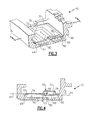
Figure 3 is a perspective partial sectional view of the BOAS segment; and -
Figure 4 is a side sectional view of the BOAS segment. -
Figure 1 schematically illustrates agas turbine engine 20, illustrated partially herein as a High Pressure Turbine (HPT)section 22 disposed along a common engine longitudinal axis A. Theengine 20 includes a Blade Outer Air Seal (BOAS)assembly 24 to provide an outer core gas path seal for theturbine section 22. It should be understood that although a BOAS assembly for a HPT of a gas turbine engine is disclosed in the illustrated embodiment, the BOAS assembly may be utilized in any section of a gas turbine engine. The BOAS segment may find beneficial use in many industries including aerospace, industrial, electricity generation, naval propulsion, pumping sets for gas and oil transmission, aircraft propulsion, vehicle engines, and stationary power plants. - The
HPT section 22 generally includes arotor assembly 26 disposed between forward and aftstationary vane assemblies 28, 30 (illustrated schematically). Outer vane supports 28A, 30A attach the respective vane assemblies to an engine case 32 (illustrated schematically). Therotor assembly 26 generally includes a multiple ofairfoils 34 circumferentially disposed around adisk 36. The distal end of eachairfoil 34 may be referred to as anairfoil tip 34T which rides adjacent to theBOAS assembly 24. - The BOAS
assembly 24 is disposed in an annulus radially between theengine case 32 and theairfoil tips 34T. TheBOAS assembly 24 generally includes a blade outer air seal (BOAS) support 38 and a multiple of blade outer air seal (BOAS)segments 40 mountable thereto (also seeFigure 2 ). The BOASsupport 38 is mounted within theengine case 32 to define forward andaft flanges BOAS segments 40. Theforward flanges 42 and theaft flanges 44 may be circumferentially segmented to receive theBOAS segments 40 in a circumferentially rotated and locked arrangement as generally understood. - Each
BOAS segment 40 includes abody 46 which defines aforward interface 48 and anaft interface 50. Theforward interface 48 and theaft interface 50 respectively engage theflanges BOAS segment 40 thereto. It should also be understood that various interfaces and BOAS assemblies may alternatively be provided. - With reference to
Figure 2 , eachBOAS segment 40 includes at least twocavities cavity 52A is axially forward ofcavity 52B but separated therefrom by acircumferential rib 56. That is, thecircumferential rib 56 essentially surrounds the engine longitudinal axis A. Eachcavity Figure 3 ). - A multiple of
edge holes 80 and a multiple offilm holes 82 provide flow communication for the secondary cooling air S from thecavities edge holes 80 are arranged generally circumferentially and the multiple offilm holes 82 are arranged generally radially with respect to the engine axis A. It should be understood that various numbers, sizes, orientations and arrangements may be provided and that theholes - The multi
impingement plate assembly 54 generally includes afirst impingement plate 60 and asecond impingement plate 62, however, any number of plates or plate sections may be utilized. Thefirst impingement plate 60 and thesecond impingement plate 62 may be welded together as a unit then welded to the body 46 (Figure 3 ). That is, the multiimpingement plate assembly 54 facilitates retrofit for single impingement plate BOAS designs. - The
first impingement plate 60 extends between aforward ledge 64, and an aft ledge 66 over thecircumferential rib 56. Thefirst impingement plate 60 generally includes awindow 67 over theforward cavity 52A and a multiple ofimpingement holes 68 over theaft cavity 52B (Figure 4 ). Alternatively, thefirst impingement plate 60 extends from thecircumferential rib 56 to theaft ledge 66 to cover theaft cavity 52B. - The
second impingement plate 62 extends between theforward ledge 64 and the aft ledge 66 over thefirst impingement plate 60. Thesecond impingement plate 62 includes aplatform section 70 which is displaced from a plane P2 which defines abase section 72. Plane P2 is parallel to plane P1 which is defined by thefirst impingement plate 60. Theplatform section 70 is imperforate while thebase section 72 includes a multiple ofimpingement holes 74. Thesecond impingement plate 62 may be welded along a periphery of thefirst impingement plate 60 to form a spaced relationship therebetween over the multiple ofimpingement holes 68. - At least one
passage 76 extends between theplatform section 70 and thebase section 72 beyond the circumferential rib 56 (best seen inFigure 3 ). That is, the at least onepassage 76 provides a transition between theplatform section 70 and thebase section 72 for communication of the secondary cooling air S from theforward cavity 52A to aplate cavity 78 between theplatform section 70 and thefirst impingement plate 60. In the disclosed non-limiting embodiment, thepassage 76 may include a set ofpassages 76 which may be generally U-shaped and is displaced from the plane P2 which includes thebase section 72 - The at least one
passage 76 provides a fluid communication path S1 (Figure 4 ) for the secondary cooling air S which enters through the multiple ofsecond impingement holes 74 into theforward cavity 52A through thewindow 67 of thefirst impingement plate 60. The secondary cooling air S provides impingement cooling of the BOAS surface in theforward cavity 52A then exits out to the core gaspath flow C (Figure 1 ) through the multiple ofedge holes 80 and the multiple offilm holes 82. - The secondary cooling air S then enters into the
plate cavity 78 through thepassage 76. From theplate cavity 78, the secondary cooling air S exits through the multiple offirst impingement holes 68 into theaft cavity 52B to provide impingement cooling in theaft cavity 52B then exits out to the core gaspath flow through the multiple ofedge holes 80. Approximately 80% of that secondary cooling air S flows out through the multiple offilm holes multiple edge holes 80. - The multi
impingement plate assembly 54 allows some of theforward cavity 52A secondary cooling air S to be reused in theaft cavity 52B which results in lower temperatures and relatively lower cooling flow requirements for theBOAS segment 40. In the disclosed non-limiting embodiment, the secondary cooling air S gaspath pressure within theBOAS segment 40 is lower axially aft along theairfoil tips 34T (Figure 1 ). Theforward cavity 52A thus has a somewhat higher static pressure than theaft cavity 52B due to the direction of primary core flow. This generates a higher pressure ratio across the BOAS and tends to "withdraw" air from theforward cavity 52A to theaft cavity 52B which facilitates operation of and cooling efficiency through the multiimpingement plate assembly 54. The higher static pressure incavity 52A also results in increased axial crossflow heat transfer coefficient (Hc) in theforward cavity 52A which results in, for example, lower temperatures, and, thereby, longer operational life of the BOAS. - The multi
impingement plate assembly 54 also provides additional cooling benefit by recirculating secondary cooling air from theforward cavity 52A into theaft cavity 52B without increased supply pressure. Estimation of cooling flow benefit through simulation is ∼0.06% turbine core flow (Wae). Thermal analysis of the multiimpingement plate assembly 54 configuration provides a benefit of ∼0.06% cooling flow reduction relative to a conventional, single-plated design which equates to a flow reduction is equivalent ∼0.006% Thrust Specific Fuel Consumption (TSFC). - It should be understood that like reference numerals identify corresponding or similar elements throughout the several drawings. It should also be understood that although a particular component arrangement is disclosed in the illustrated embodiment, other arrangements will benefit herefrom.
- Although particular step sequences are shown, described, and claimed, it should be understood that steps may be performed in any order, separated or combined unless otherwise indicated and will still benefit from the present invention.
- The foregoing description is exemplary rather than defined by the limitations within. Many modifications and variations of the present invention are possible in light of the above teachings. The disclosed embodiments of this invention have been disclosed, however, one of ordinary skill in the art would recognize that certain modifications would come within the scope of this invention. It is, therefore, to be understood that within the scope of the appended claims, the invention may be practiced otherwise than as specifically described. For that reason the following claims should be studied to determine the true scope and content of this invention.
Claims (15)
- A multi impingement plate assembly (54) for a Blade Outer Air Seal (BOAS) (24) comprising:a first impingement plate (60) which defines a multiple of first impingement plate holes (68); anda second impingement plate (62) attached to said first impingement plate (60), said second impingement plate (62) including a platform section (70) spaced away from said multiple of first impingement plate holes (62) to define a plate cavity (78).
- The multi impingement plate assembly as recited in claim 1, wherein said platform section (70) is solid.
- The multi impingement plate assembly as recited in claim 1 or 2, wherein said second impingement plate (62) includes a base section (72) defined within a plane (P2), said platform section (70) parallel and spaced away from said plane (P2).
- The multi impingement plate assembly as recited in claim 3, further comprising at least one passage (76) which transitions between said base section (72) and said platform section (70).
- The multi impingement plate assembly as recited in claim 3 or 4, wherein said base section (72) includes a multiple of second impingement holes (74).
- The multi impingement plate assembly as recited in any preceding claim, wherein said second impingement plate (62) includes a multiple of second impingement holes (74) spaced axially offset from said multiple of first impingement holes (68).
- The multi impingement plate assembly as recited in any preceding claim, wherein said first impingement plate (60) includes a window (67) adjacent to said multiple of first impingement plate holes (68).
- A blade outer air seal assembly (24) comprising:a body (46) which defines a first cavity (52A) separated from a second cavity (52B) by a circumferential rib (56); anda multi impingement plate assembly (54) which defines a plate cavity (78), said multi impingement plate assembly circulates a secondary cooling air flow (S1) between said first cavity (52A) and said second cavity (52B) through said plate cavity (78).
- The blade outer air seal assembly as recited in claim 8, wherein said multi impingement plate assembly (54) includes a first impingement plate (60) which defines a multiple of first impingement plate holes (68) and a second impingement plate (62) attached to said first impingement plate (60).
- The blade outer air seal assembly as recited in claim 8 or 9, wherein said multi impingement plate assembly (54) includes a first impingement plate (60) and a second impingement plate (62) attached to said first impingement plate (60) to define said plate cavity (78).
- The blade outer air seal assembly as recited in any of claims 8 to 10, wherein said multi impingement plate assembly (54) includes a first impingement plate (60) with a multiple of first impingement plate (68) holes adjacent to said second cavity (52B), and wherein, optionally, said multi impingement plate assembly (54) includes a second impingement plate (62) with a multiple of second impingement plate holes (74) adjacent to said first cavity (52A).
- The blade outer air seal assembly as recited in claim 11, wherein said second impingement plate (62) defines a passage (76) which spans said circumferential rib (56) to provide fluid communication with said plate cavity (78).
- The blade outer air seal assembly as recited in any of claims 8 to 12, wherein said first cavity (52A) and said second cavity (52B) include a a multiple of edge holes (80) to communicate a cooling flow to a core flow.
- The blade outer air seal assembly of any of claims 8 to 13, wherein said multi impingement plate assembly is a multi impingement plate assembly as recited in any of claims 1 to 7.
- A method of communicating a secondary cooling airflow within a gas turbine engine comprising:segregating a first cavity (52A) from a second cavity (52B) by a circumferential rib (56); andcommunicating secondary cooling airflow between the first cavity (52A) and the second cavity (52B) through a plate cavity (78) of a multi impingement plate assembly (54), further optionally comprising communicating the secondary cooling airflow into the first cavity (52A) through a multiple of second cooling air holes (74) in a second impingement plate (62) and a window (67) of a first impingement plate (60), further optionally comprising communicating the secondary cooling airflow between the first cavity (52A) and the second cavity (52B) through a passage (76) in communication with the plate cavity (78), further optionally comprising communicating the secondary cooling airflow from the plate cavity (78) into the secondary cavity (52B) though a multiple of first cooling air holes (68) in the first impingement plate (60) and further optionally communicating the secondary cooling airflow from the first cavity (52A) and the second cavity (52B) through a multiple of edge holes (80) to a core flow.
Applications Claiming Priority (1)
| Application Number | Priority Date | Filing Date | Title |
|---|---|---|---|
| US13/215,304 US9080458B2 (en) | 2011-08-23 | 2011-08-23 | Blade outer air seal with multi impingement plate assembly |
Publications (3)
| Publication Number | Publication Date |
|---|---|
| EP2562365A2 true EP2562365A2 (en) | 2013-02-27 |
| EP2562365A3 EP2562365A3 (en) | 2016-08-31 |
| EP2562365B1 EP2562365B1 (en) | 2020-02-26 |
Family
ID=46750225
Family Applications (1)
| Application Number | Title | Priority Date | Filing Date |
|---|---|---|---|
| EP12181419.8A Active EP2562365B1 (en) | 2011-08-23 | 2012-08-22 | Blade outer air seal with multi impingement plate assembly |
Country Status (2)
| Country | Link |
|---|---|
| US (1) | US9080458B2 (en) |
| EP (1) | EP2562365B1 (en) |
Cited By (7)
| Publication number | Priority date | Publication date | Assignee | Title |
|---|---|---|---|---|
| WO2015026598A1 (en) * | 2013-08-20 | 2015-02-26 | United Technologies Corporation | Gas turbine engine component providing prioritized cooling |
| EP2949871A1 (en) * | 2014-05-07 | 2015-12-02 | United Technologies Corporation | Variable vane segment |
| EP3257609A3 (en) * | 2016-06-14 | 2018-04-11 | Rolls-Royce plc | A semi-annular component and method of manufacture |
| US10612406B2 (en) | 2018-04-19 | 2020-04-07 | United Technologies Corporation | Seal assembly with shield for gas turbine engines |
| US11220924B2 (en) | 2019-09-26 | 2022-01-11 | Raytheon Technologies Corporation | Double box composite seal assembly with insert for gas turbine engine |
| US11352897B2 (en) | 2019-09-26 | 2022-06-07 | Raytheon Technologies Corporation | Double box composite seal assembly for gas turbine engine |
| US11359507B2 (en) | 2019-09-26 | 2022-06-14 | Raytheon Technologies Corporation | Double box composite seal assembly with fiber density arrangement for gas turbine engine |
Families Citing this family (27)
| Publication number | Priority date | Publication date | Assignee | Title |
|---|---|---|---|---|
| US8826668B2 (en) * | 2011-08-02 | 2014-09-09 | Siemens Energy, Inc. | Two stage serial impingement cooling for isogrid structures |
| WO2014066276A2 (en) | 2012-10-26 | 2014-05-01 | Kraft Robert J | Gas turbine energy supplementing systems and heating systems, and methods of making and using the same |
| US20140130504A1 (en) * | 2012-11-12 | 2014-05-15 | General Electric Company | System for cooling a hot gas component for a combustor of a gas turbine |
| EP2956627B1 (en) * | 2013-02-15 | 2018-07-25 | United Technologies Corporation | Gas turbine engine component with combined mate face and platform cooling |
| US9638047B1 (en) * | 2013-11-18 | 2017-05-02 | Florida Turbine Technologies, Inc. | Multiple wall impingement plate for sequential impingement cooling of an endwall |
| US9683444B1 (en) * | 2013-11-18 | 2017-06-20 | Florida Turbine Technologies, Inc. | Multiple wall impingement plate for sequential impingement cooling of a turbine hot part |
| US10240475B2 (en) | 2013-12-03 | 2019-03-26 | United Technologies Corporation | Heat shields for air seals |
| US10316683B2 (en) | 2014-04-16 | 2019-06-11 | United Technologies Corporation | Gas turbine engine blade outer air seal thermal control system |
| US9689276B2 (en) | 2014-07-18 | 2017-06-27 | Pratt & Whitney Canada Corp. | Annular ring assembly for shroud cooling |
| EP3023596B1 (en) | 2014-11-20 | 2019-01-02 | United Technologies Corporation | Internally cooled turbine platform |
| US10358979B2 (en) | 2015-02-05 | 2019-07-23 | Powerphase Llc | Turbocooled vane of a gas turbine engine |
| US10443501B2 (en) | 2015-02-05 | 2019-10-15 | Powerphase Llc | Turbocooled vane of a gas turbine engine |
| US10215099B2 (en) * | 2015-02-06 | 2019-02-26 | United Technologies Corporation | System and method for limiting movement of a retainer ring of a gas turbine engine |
| WO2017052794A2 (en) * | 2015-08-04 | 2017-03-30 | Powerphase Llc | Turbocooled vane of a gas turbine engine |
| JP6587251B2 (en) * | 2015-11-27 | 2019-10-09 | 三菱日立パワーシステムズ株式会社 | Flow path forming plate, flow path forming assembly member and vane including the same, gas turbine, flow path forming plate manufacturing method, and flow path forming plate remodeling method |
| US20170198602A1 (en) * | 2016-01-11 | 2017-07-13 | General Electric Company | Gas turbine engine with a cooled nozzle segment |
| US10309253B2 (en) | 2016-01-13 | 2019-06-04 | United Technologies Corporation | Gas turbine engine blade outer air seal profile |
| US10036271B2 (en) | 2016-01-13 | 2018-07-31 | United Technologies Corporation | Gas turbine engine blade outer air seal profile |
| EP3306040B1 (en) * | 2016-10-08 | 2019-12-11 | Ansaldo Energia Switzerland AG | Stator heat shield segment for a gas turbine power plant |
| US10634353B2 (en) | 2017-01-12 | 2020-04-28 | General Electric Company | Fuel nozzle assembly with micro channel cooling |
| US10815812B2 (en) * | 2017-05-12 | 2020-10-27 | Raytheon Technologies Corporation | Geometry optimized blade outer air seal for thermal loads |
| US10502093B2 (en) * | 2017-12-13 | 2019-12-10 | Pratt & Whitney Canada Corp. | Turbine shroud cooling |
| JP7065941B2 (en) * | 2018-03-07 | 2022-05-12 | 川崎重工業株式会社 | Gas turbine shroud mounting structure, shroud assembly and shroud elements |
| US10989068B2 (en) | 2018-07-19 | 2021-04-27 | General Electric Company | Turbine shroud including plurality of cooling passages |
| US10837315B2 (en) * | 2018-10-25 | 2020-11-17 | General Electric Company | Turbine shroud including cooling passages in communication with collection plenums |
| US10975724B2 (en) * | 2018-10-30 | 2021-04-13 | General Electric Company | System and method for shroud cooling in a gas turbine engine |
| FR3153108A1 (en) * | 2023-09-14 | 2025-03-21 | Safran Aircraft Engines | Improved gas turbine fixed ring cooling system |
Family Cites Families (36)
| Publication number | Priority date | Publication date | Assignee | Title |
|---|---|---|---|---|
| US3348622A (en) | 1962-12-24 | 1967-10-24 | Papst Hermann | Boundary layer control |
| US3728039A (en) | 1966-11-02 | 1973-04-17 | Gen Electric | Fluid cooled porous stator structure |
| US3597102A (en) | 1968-06-10 | 1971-08-03 | English Electric Co Ltd | Turbines |
| US3825364A (en) | 1972-06-09 | 1974-07-23 | Gen Electric | Porous abradable turbine shroud |
| FR2280791A1 (en) | 1974-07-31 | 1976-02-27 | Snecma | IMPROVEMENTS IN ADJUSTING THE CLEARANCE BETWEEN THE BLADES AND THE STATOR OF A TURBINE |
| US4177004A (en) | 1977-10-31 | 1979-12-04 | General Electric Company | Combined turbine shroud and vane support structure |
| FR2416345A1 (en) | 1978-01-31 | 1979-08-31 | Snecma | IMPACT COOLING DEVICE FOR TURBINE SEGMENTS OF A TURBOREACTOR |
| US4526226A (en) * | 1981-08-31 | 1985-07-02 | General Electric Company | Multiple-impingement cooled structure |
| US4573865A (en) | 1981-08-31 | 1986-03-04 | General Electric Company | Multiple-impingement cooled structure |
| US4465429A (en) | 1982-02-01 | 1984-08-14 | Westinghouse Electric Corp. | Steam turbine with superheated blade disc cavities |
| FR2574473B1 (en) | 1984-11-22 | 1987-03-20 | Snecma | TURBINE RING FOR A GAS TURBOMACHINE |
| US5601402A (en) | 1986-06-06 | 1997-02-11 | The United States Of America As Represented By The Secretary Of The Air Force | Turbo machine shroud-to-rotor blade dynamic clearance control |
| US5048288A (en) | 1988-12-20 | 1991-09-17 | United Technologies Corporation | Combined turbine stator cooling and turbine tip clearance control |
| US5375973A (en) | 1992-12-23 | 1994-12-27 | United Technologies Corporation | Turbine blade outer air seal with optimized cooling |
| US5423659A (en) | 1994-04-28 | 1995-06-13 | United Technologies Corporation | Shroud segment having a cut-back retaining hook |
| US5480281A (en) | 1994-06-30 | 1996-01-02 | General Electric Co. | Impingement cooling apparatus for turbine shrouds having ducts of increasing cross-sectional area in the direction of post-impingement cooling flow |
| GB2310255B (en) | 1996-02-13 | 1999-06-16 | Rolls Royce Plc | A turbomachine |
| FR2766517B1 (en) | 1997-07-24 | 1999-09-03 | Snecma | DEVICE FOR VENTILATION OF A TURBOMACHINE RING |
| US5993150A (en) | 1998-01-16 | 1999-11-30 | General Electric Company | Dual cooled shroud |
| US6146091A (en) | 1998-03-03 | 2000-11-14 | Mitsubishi Heavy Industries, Ltd. | Gas turbine cooling structure |
| US6126389A (en) | 1998-09-02 | 2000-10-03 | General Electric Co. | Impingement cooling for the shroud of a gas turbine |
| US6368054B1 (en) | 1999-12-14 | 2002-04-09 | Pratt & Whitney Canada Corp. | Split ring for tip clearance control |
| FR2803871B1 (en) | 2000-01-13 | 2002-06-07 | Snecma Moteurs | DIAMETER ADJUSTMENT ARRANGEMENT OF A GAS TURBINE STATOR |
| JP3632003B2 (en) | 2000-03-07 | 2005-03-23 | 三菱重工業株式会社 | Gas turbine split ring |
| FR2819010B1 (en) | 2001-01-04 | 2004-05-28 | Snecma Moteurs | STATOR RING SUPPORT AREA OF THE TURBINE HIGH PRESSURE TURBINE ROTATOR WITH A TURBOMACHINE |
| US6612808B2 (en) | 2001-11-29 | 2003-09-02 | General Electric Company | Article wall with interrupted ribbed heat transfer surface |
| US6779597B2 (en) * | 2002-01-16 | 2004-08-24 | General Electric Company | Multiple impingement cooled structure |
| US6659716B1 (en) | 2002-07-15 | 2003-12-09 | Mitsubishi Heavy Industries, Ltd. | Gas turbine having thermally insulating rings |
| US6877952B2 (en) | 2002-09-09 | 2005-04-12 | Florida Turbine Technologies, Inc | Passive clearance control |
| US6899518B2 (en) | 2002-12-23 | 2005-05-31 | Pratt & Whitney Canada Corp. | Turbine shroud segment apparatus for reusing cooling air |
| US7063503B2 (en) | 2004-04-15 | 2006-06-20 | Pratt & Whitney Canada Corp. | Turbine shroud cooling system |
| US7097418B2 (en) | 2004-06-18 | 2006-08-29 | Pratt & Whitney Canada Corp. | Double impingement vane platform cooling |
| US7306424B2 (en) | 2004-12-29 | 2007-12-11 | United Technologies Corporation | Blade outer seal with micro axial flow cooling system |
| US7670108B2 (en) | 2006-11-21 | 2010-03-02 | Siemens Energy, Inc. | Air seal unit adapted to be positioned adjacent blade structure in a gas turbine |
| US7665962B1 (en) * | 2007-01-26 | 2010-02-23 | Florida Turbine Technologies, Inc. | Segmented ring for an industrial gas turbine |
| US8303247B2 (en) * | 2007-09-06 | 2012-11-06 | United Technologies Corporation | Blade outer air seal |
-
2011
- 2011-08-23 US US13/215,304 patent/US9080458B2/en active Active
-
2012
- 2012-08-22 EP EP12181419.8A patent/EP2562365B1/en active Active
Non-Patent Citations (1)
| Title |
|---|
| None |
Cited By (9)
| Publication number | Priority date | Publication date | Assignee | Title |
|---|---|---|---|---|
| WO2015026598A1 (en) * | 2013-08-20 | 2015-02-26 | United Technologies Corporation | Gas turbine engine component providing prioritized cooling |
| US10215051B2 (en) | 2013-08-20 | 2019-02-26 | United Technologies Corporation | Gas turbine engine component providing prioritized cooling |
| EP2949871A1 (en) * | 2014-05-07 | 2015-12-02 | United Technologies Corporation | Variable vane segment |
| EP3257609A3 (en) * | 2016-06-14 | 2018-04-11 | Rolls-Royce plc | A semi-annular component and method of manufacture |
| US10612406B2 (en) | 2018-04-19 | 2020-04-07 | United Technologies Corporation | Seal assembly with shield for gas turbine engines |
| US11220924B2 (en) | 2019-09-26 | 2022-01-11 | Raytheon Technologies Corporation | Double box composite seal assembly with insert for gas turbine engine |
| US11352897B2 (en) | 2019-09-26 | 2022-06-07 | Raytheon Technologies Corporation | Double box composite seal assembly for gas turbine engine |
| US11359507B2 (en) | 2019-09-26 | 2022-06-14 | Raytheon Technologies Corporation | Double box composite seal assembly with fiber density arrangement for gas turbine engine |
| US11732597B2 (en) | 2019-09-26 | 2023-08-22 | Raytheon Technologies Corporation | Double box composite seal assembly with insert for gas turbine engine |
Also Published As
| Publication number | Publication date |
|---|---|
| US20130051972A1 (en) | 2013-02-28 |
| EP2562365B1 (en) | 2020-02-26 |
| EP2562365A3 (en) | 2016-08-31 |
| US9080458B2 (en) | 2015-07-14 |
Similar Documents
| Publication | Publication Date | Title |
|---|---|---|
| EP2562365B1 (en) | Blade outer air seal with multi impingement plate assembly | |
| EP2855891B1 (en) | Blade outer air seal for a gas turbine engine | |
| EP1965031B1 (en) | Blade outer air seal assembly | |
| EP2093384B1 (en) | Filter system for blade outer air seal | |
| US9988934B2 (en) | Gas turbine engines including channel-cooled hooks for retaining a part relative to an engine casing structure | |
| US10612388B2 (en) | Gas turbine engine airfoil cooling circuit | |
| EP2948636B1 (en) | Gas turbine engine component having contoured rib end | |
| US20110243717A1 (en) | Dead ended bulbed rib geometry for a gas turbine engine | |
| EP2412926A2 (en) | Hollow blade for a gas turbine | |
| EP3211179B1 (en) | Airfoil having pedestals in trailing edge cavity | |
| WO2014047022A1 (en) | Gas turbine engine component cooling circuit | |
| EP3084184B1 (en) | Blade outer air seal cooling passage | |
| WO2021087503A1 (en) | Turbine blade, method of manufacturing a turbine blade and method of refurbishing a turbine blade | |
| EP3047111B1 (en) | Component for a gas turbine engine, corresponding gas turbine engine and method of cooling | |
| EP2551468B1 (en) | Blade outer air seal assembly with passage joined cavities and corresponding operating method | |
| EP2957721B1 (en) | Turbine section of a gas turbine engine, with disk cooling and an interstage seal having a particular geometry | |
| EP3578759B1 (en) | Airfoil and corresponding method of directing a cooling flow | |
| US20170022823A1 (en) | Turbine rotors including turbine blades having turbulator-cooled tip pockets |
Legal Events
| Date | Code | Title | Description |
|---|---|---|---|
| PUAI | Public reference made under article 153(3) epc to a published international application that has entered the european phase |
Free format text: ORIGINAL CODE: 0009012 |
|
| AK | Designated contracting states |
Kind code of ref document: A2 Designated state(s): AL AT BE BG CH CY CZ DE DK EE ES FI FR GB GR HR HU IE IS IT LI LT LU LV MC MK MT NL NO PL PT RO RS SE SI SK SM TR |
|
| AX | Request for extension of the european patent |
Extension state: BA ME |
|
| PUAL | Search report despatched |
Free format text: ORIGINAL CODE: 0009013 |
|
| AK | Designated contracting states |
Kind code of ref document: A3 Designated state(s): AL AT BE BG CH CY CZ DE DK EE ES FI FR GB GR HR HU IE IS IT LI LT LU LV MC MK MT NL NO PL PT RO RS SE SI SK SM TR |
|
| AX | Request for extension of the european patent |
Extension state: BA ME |
|
| RIC1 | Information provided on ipc code assigned before grant |
Ipc: F01D 25/12 20060101ALI20160726BHEP Ipc: F01D 11/24 20060101ALI20160726BHEP Ipc: F01D 11/08 20060101AFI20160726BHEP |
|
| RAP1 | Party data changed (applicant data changed or rights of an application transferred) |
Owner name: UNITED TECHNOLOGIES CORPORATION |
|
| STAA | Information on the status of an ep patent application or granted ep patent |
Free format text: STATUS: REQUEST FOR EXAMINATION WAS MADE |
|
| 17P | Request for examination filed |
Effective date: 20170228 |
|
| RBV | Designated contracting states (corrected) |
Designated state(s): AL AT BE BG CH CY CZ DE DK EE ES FI FR GB GR HR HU IE IS IT LI LT LU LV MC MK MT NL NO PL PT RO RS SE SI SK SM TR |
|
| GRAP | Despatch of communication of intention to grant a patent |
Free format text: ORIGINAL CODE: EPIDOSNIGR1 |
|
| STAA | Information on the status of an ep patent application or granted ep patent |
Free format text: STATUS: GRANT OF PATENT IS INTENDED |
|
| INTG | Intention to grant announced |
Effective date: 20190902 |
|
| GRAS | Grant fee paid |
Free format text: ORIGINAL CODE: EPIDOSNIGR3 |
|
| GRAA | (expected) grant |
Free format text: ORIGINAL CODE: 0009210 |
|
| STAA | Information on the status of an ep patent application or granted ep patent |
Free format text: STATUS: THE PATENT HAS BEEN GRANTED |
|
| AK | Designated contracting states |
Kind code of ref document: B1 Designated state(s): AL AT BE BG CH CY CZ DE DK EE ES FI FR GB GR HR HU IE IS IT LI LT LU LV MC MK MT NL NO PL PT RO RS SE SI SK SM TR |
|
| REG | Reference to a national code |
Ref country code: GB Ref legal event code: FG4D |
|
| REG | Reference to a national code |
Ref country code: CH Ref legal event code: EP |
|
| REG | Reference to a national code |
Ref country code: AT Ref legal event code: REF Ref document number: 1237868 Country of ref document: AT Kind code of ref document: T Effective date: 20200315 |
|
| REG | Reference to a national code |
Ref country code: IE Ref legal event code: FG4D |
|
| REG | Reference to a national code |
Ref country code: DE Ref legal event code: R096 Ref document number: 602012068016 Country of ref document: DE |
|
| PG25 | Lapsed in a contracting state [announced via postgrant information from national office to epo] |
Ref country code: RS Free format text: LAPSE BECAUSE OF FAILURE TO SUBMIT A TRANSLATION OF THE DESCRIPTION OR TO PAY THE FEE WITHIN THE PRESCRIBED TIME-LIMIT Effective date: 20200226 Ref country code: FI Free format text: LAPSE BECAUSE OF FAILURE TO SUBMIT A TRANSLATION OF THE DESCRIPTION OR TO PAY THE FEE WITHIN THE PRESCRIBED TIME-LIMIT Effective date: 20200226 Ref country code: NO Free format text: LAPSE BECAUSE OF FAILURE TO SUBMIT A TRANSLATION OF THE DESCRIPTION OR TO PAY THE FEE WITHIN THE PRESCRIBED TIME-LIMIT Effective date: 20200526 |
|
| REG | Reference to a national code |
Ref country code: NL Ref legal event code: MP Effective date: 20200226 |
|
| REG | Reference to a national code |
Ref country code: LT Ref legal event code: MG4D |
|
| PG25 | Lapsed in a contracting state [announced via postgrant information from national office to epo] |
Ref country code: IS Free format text: LAPSE BECAUSE OF FAILURE TO SUBMIT A TRANSLATION OF THE DESCRIPTION OR TO PAY THE FEE WITHIN THE PRESCRIBED TIME-LIMIT Effective date: 20200626 Ref country code: GR Free format text: LAPSE BECAUSE OF FAILURE TO SUBMIT A TRANSLATION OF THE DESCRIPTION OR TO PAY THE FEE WITHIN THE PRESCRIBED TIME-LIMIT Effective date: 20200527 Ref country code: SE Free format text: LAPSE BECAUSE OF FAILURE TO SUBMIT A TRANSLATION OF THE DESCRIPTION OR TO PAY THE FEE WITHIN THE PRESCRIBED TIME-LIMIT Effective date: 20200226 Ref country code: LV Free format text: LAPSE BECAUSE OF FAILURE TO SUBMIT A TRANSLATION OF THE DESCRIPTION OR TO PAY THE FEE WITHIN THE PRESCRIBED TIME-LIMIT Effective date: 20200226 Ref country code: HR Free format text: LAPSE BECAUSE OF FAILURE TO SUBMIT A TRANSLATION OF THE DESCRIPTION OR TO PAY THE FEE WITHIN THE PRESCRIBED TIME-LIMIT Effective date: 20200226 Ref country code: BG Free format text: LAPSE BECAUSE OF FAILURE TO SUBMIT A TRANSLATION OF THE DESCRIPTION OR TO PAY THE FEE WITHIN THE PRESCRIBED TIME-LIMIT Effective date: 20200526 |
|
| PG25 | Lapsed in a contracting state [announced via postgrant information from national office to epo] |
Ref country code: NL Free format text: LAPSE BECAUSE OF FAILURE TO SUBMIT A TRANSLATION OF THE DESCRIPTION OR TO PAY THE FEE WITHIN THE PRESCRIBED TIME-LIMIT Effective date: 20200226 |
|
| PG25 | Lapsed in a contracting state [announced via postgrant information from national office to epo] |
Ref country code: PT Free format text: LAPSE BECAUSE OF FAILURE TO SUBMIT A TRANSLATION OF THE DESCRIPTION OR TO PAY THE FEE WITHIN THE PRESCRIBED TIME-LIMIT Effective date: 20200719 Ref country code: DK Free format text: LAPSE BECAUSE OF FAILURE TO SUBMIT A TRANSLATION OF THE DESCRIPTION OR TO PAY THE FEE WITHIN THE PRESCRIBED TIME-LIMIT Effective date: 20200226 Ref country code: ES Free format text: LAPSE BECAUSE OF FAILURE TO SUBMIT A TRANSLATION OF THE DESCRIPTION OR TO PAY THE FEE WITHIN THE PRESCRIBED TIME-LIMIT Effective date: 20200226 Ref country code: LT Free format text: LAPSE BECAUSE OF FAILURE TO SUBMIT A TRANSLATION OF THE DESCRIPTION OR TO PAY THE FEE WITHIN THE PRESCRIBED TIME-LIMIT Effective date: 20200226 Ref country code: EE Free format text: LAPSE BECAUSE OF FAILURE TO SUBMIT A TRANSLATION OF THE DESCRIPTION OR TO PAY THE FEE WITHIN THE PRESCRIBED TIME-LIMIT Effective date: 20200226 Ref country code: SM Free format text: LAPSE BECAUSE OF FAILURE TO SUBMIT A TRANSLATION OF THE DESCRIPTION OR TO PAY THE FEE WITHIN THE PRESCRIBED TIME-LIMIT Effective date: 20200226 Ref country code: SK Free format text: LAPSE BECAUSE OF FAILURE TO SUBMIT A TRANSLATION OF THE DESCRIPTION OR TO PAY THE FEE WITHIN THE PRESCRIBED TIME-LIMIT Effective date: 20200226 Ref country code: RO Free format text: LAPSE BECAUSE OF FAILURE TO SUBMIT A TRANSLATION OF THE DESCRIPTION OR TO PAY THE FEE WITHIN THE PRESCRIBED TIME-LIMIT Effective date: 20200226 Ref country code: CZ Free format text: LAPSE BECAUSE OF FAILURE TO SUBMIT A TRANSLATION OF THE DESCRIPTION OR TO PAY THE FEE WITHIN THE PRESCRIBED TIME-LIMIT Effective date: 20200226 |
|
| REG | Reference to a national code |
Ref country code: AT Ref legal event code: MK05 Ref document number: 1237868 Country of ref document: AT Kind code of ref document: T Effective date: 20200226 |
|
| REG | Reference to a national code |
Ref country code: DE Ref legal event code: R097 Ref document number: 602012068016 Country of ref document: DE |
|
| PLBE | No opposition filed within time limit |
Free format text: ORIGINAL CODE: 0009261 |
|
| STAA | Information on the status of an ep patent application or granted ep patent |
Free format text: STATUS: NO OPPOSITION FILED WITHIN TIME LIMIT |
|
| PG25 | Lapsed in a contracting state [announced via postgrant information from national office to epo] |
Ref country code: IT Free format text: LAPSE BECAUSE OF FAILURE TO SUBMIT A TRANSLATION OF THE DESCRIPTION OR TO PAY THE FEE WITHIN THE PRESCRIBED TIME-LIMIT Effective date: 20200226 Ref country code: AT Free format text: LAPSE BECAUSE OF FAILURE TO SUBMIT A TRANSLATION OF THE DESCRIPTION OR TO PAY THE FEE WITHIN THE PRESCRIBED TIME-LIMIT Effective date: 20200226 |
|
| 26N | No opposition filed |
Effective date: 20201127 |
|
| PG25 | Lapsed in a contracting state [announced via postgrant information from national office to epo] |
Ref country code: SI Free format text: LAPSE BECAUSE OF FAILURE TO SUBMIT A TRANSLATION OF THE DESCRIPTION OR TO PAY THE FEE WITHIN THE PRESCRIBED TIME-LIMIT Effective date: 20200226 Ref country code: PL Free format text: LAPSE BECAUSE OF FAILURE TO SUBMIT A TRANSLATION OF THE DESCRIPTION OR TO PAY THE FEE WITHIN THE PRESCRIBED TIME-LIMIT Effective date: 20200226 |
|
| PG25 | Lapsed in a contracting state [announced via postgrant information from national office to epo] |
Ref country code: MC Free format text: LAPSE BECAUSE OF FAILURE TO SUBMIT A TRANSLATION OF THE DESCRIPTION OR TO PAY THE FEE WITHIN THE PRESCRIBED TIME-LIMIT Effective date: 20200226 |
|
| REG | Reference to a national code |
Ref country code: CH Ref legal event code: PL |
|
| PG25 | Lapsed in a contracting state [announced via postgrant information from national office to epo] |
Ref country code: LU Free format text: LAPSE BECAUSE OF NON-PAYMENT OF DUE FEES Effective date: 20200822 Ref country code: LI Free format text: LAPSE BECAUSE OF NON-PAYMENT OF DUE FEES Effective date: 20200831 Ref country code: CH Free format text: LAPSE BECAUSE OF NON-PAYMENT OF DUE FEES Effective date: 20200831 |
|
| REG | Reference to a national code |
Ref country code: BE Ref legal event code: MM Effective date: 20200831 |
|
| PG25 | Lapsed in a contracting state [announced via postgrant information from national office to epo] |
Ref country code: BE Free format text: LAPSE BECAUSE OF NON-PAYMENT OF DUE FEES Effective date: 20200831 Ref country code: IE Free format text: LAPSE BECAUSE OF NON-PAYMENT OF DUE FEES Effective date: 20200822 |
|
| PG25 | Lapsed in a contracting state [announced via postgrant information from national office to epo] |
Ref country code: TR Free format text: LAPSE BECAUSE OF FAILURE TO SUBMIT A TRANSLATION OF THE DESCRIPTION OR TO PAY THE FEE WITHIN THE PRESCRIBED TIME-LIMIT Effective date: 20200226 Ref country code: MT Free format text: LAPSE BECAUSE OF FAILURE TO SUBMIT A TRANSLATION OF THE DESCRIPTION OR TO PAY THE FEE WITHIN THE PRESCRIBED TIME-LIMIT Effective date: 20200226 Ref country code: CY Free format text: LAPSE BECAUSE OF FAILURE TO SUBMIT A TRANSLATION OF THE DESCRIPTION OR TO PAY THE FEE WITHIN THE PRESCRIBED TIME-LIMIT Effective date: 20200226 |
|
| PG25 | Lapsed in a contracting state [announced via postgrant information from national office to epo] |
Ref country code: MK Free format text: LAPSE BECAUSE OF FAILURE TO SUBMIT A TRANSLATION OF THE DESCRIPTION OR TO PAY THE FEE WITHIN THE PRESCRIBED TIME-LIMIT Effective date: 20200226 Ref country code: AL Free format text: LAPSE BECAUSE OF FAILURE TO SUBMIT A TRANSLATION OF THE DESCRIPTION OR TO PAY THE FEE WITHIN THE PRESCRIBED TIME-LIMIT Effective date: 20200226 |
|
| REG | Reference to a national code |
Ref country code: DE Ref legal event code: R081 Ref document number: 602012068016 Country of ref document: DE Owner name: RAYTHEON TECHNOLOGIES CORPORATION (N.D.GES.D.S, US Free format text: FORMER OWNER: UNITED TECHNOLOGIES CORPORATION, FARMINGTON, CONN., US |
|
| P01 | Opt-out of the competence of the unified patent court (upc) registered |
Effective date: 20230520 |
|
| PGFP | Annual fee paid to national office [announced via postgrant information from national office to epo] |
Ref country code: DE Payment date: 20240723 Year of fee payment: 13 |
|
| PGFP | Annual fee paid to national office [announced via postgrant information from national office to epo] |
Ref country code: GB Payment date: 20240723 Year of fee payment: 13 |
|
| PGFP | Annual fee paid to national office [announced via postgrant information from national office to epo] |
Ref country code: FR Payment date: 20240723 Year of fee payment: 13 |
|
| REG | Reference to a national code |
Ref country code: DE Ref legal event code: R119 Ref document number: 602012068016 Country of ref document: DE |