EP2562140A1 - Air-drying device for sludge - Google Patents
Air-drying device for sludge Download PDFInfo
- Publication number
- EP2562140A1 EP2562140A1 EP10844989A EP10844989A EP2562140A1 EP 2562140 A1 EP2562140 A1 EP 2562140A1 EP 10844989 A EP10844989 A EP 10844989A EP 10844989 A EP10844989 A EP 10844989A EP 2562140 A1 EP2562140 A1 EP 2562140A1
- Authority
- EP
- European Patent Office
- Prior art keywords
- air
- drying
- dehumidifying
- connects
- drying mechanism
- Prior art date
- Legal status (The legal status is an assumption and is not a legal conclusion. Google has not performed a legal analysis and makes no representation as to the accuracy of the status listed.)
- Withdrawn
Links
Images

Classifications
-
- C—CHEMISTRY; METALLURGY
- C02—TREATMENT OF WATER, WASTE WATER, SEWAGE, OR SLUDGE
- C02F—TREATMENT OF WATER, WASTE WATER, SEWAGE, OR SLUDGE
- C02F11/00—Treatment of sludge; Devices therefor
- C02F11/12—Treatment of sludge; Devices therefor by de-watering, drying or thickening
-
- F—MECHANICAL ENGINEERING; LIGHTING; HEATING; WEAPONS; BLASTING
- F26—DRYING
- F26B—DRYING SOLID MATERIALS OR OBJECTS BY REMOVING LIQUID THEREFROM
- F26B21/00—Arrangements for supplying or controlling air or other gases for drying solid materials or objects
- F26B21/30—Controlling, e.g. regulating, parameters of gas supply
- F26B21/33—Humidity
- F26B21/333—Humidity by condensing the moisture in the drying medium, which may be recycled, e.g. using a heat pump cycle
-
- C—CHEMISTRY; METALLURGY
- C02—TREATMENT OF WATER, WASTE WATER, SEWAGE, OR SLUDGE
- C02F—TREATMENT OF WATER, WASTE WATER, SEWAGE, OR SLUDGE
- C02F1/00—Treatment of water, waste water, or sewage
- C02F1/02—Treatment of water, waste water, or sewage by heating
- C02F1/04—Treatment of water, waste water, or sewage by heating by distillation or evaporation
-
- C—CHEMISTRY; METALLURGY
- C02—TREATMENT OF WATER, WASTE WATER, SEWAGE, OR SLUDGE
- C02F—TREATMENT OF WATER, WASTE WATER, SEWAGE, OR SLUDGE
- C02F11/00—Treatment of sludge; Devices therefor
- C02F11/12—Treatment of sludge; Devices therefor by de-watering, drying or thickening
- C02F11/13—Treatment of sludge; Devices therefor by de-watering, drying or thickening by heating
-
- F—MECHANICAL ENGINEERING; LIGHTING; HEATING; WEAPONS; BLASTING
- F26—DRYING
- F26B—DRYING SOLID MATERIALS OR OBJECTS BY REMOVING LIQUID THEREFROM
- F26B17/00—Machines or apparatus for drying materials in loose, plastic, or fluidised form, e.g. granules, staple fibres, with progressive movement
- F26B17/18—Machines or apparatus for drying materials in loose, plastic, or fluidised form, e.g. granules, staple fibres, with progressive movement with movement performed by rotating helical blades or other rotary conveyors which may be heated moving materials in stationary chambers, e.g. troughs
- F26B17/20—Machines or apparatus for drying materials in loose, plastic, or fluidised form, e.g. granules, staple fibres, with progressive movement with movement performed by rotating helical blades or other rotary conveyors which may be heated moving materials in stationary chambers, e.g. troughs the axis of rotation being horizontal or slightly inclined
- F26B17/205—Machines or apparatus for drying materials in loose, plastic, or fluidised form, e.g. granules, staple fibres, with progressive movement with movement performed by rotating helical blades or other rotary conveyors which may be heated moving materials in stationary chambers, e.g. troughs the axis of rotation being horizontal or slightly inclined with multiple chambers, e.g. troughs, in superimposed arrangement
-
- F—MECHANICAL ENGINEERING; LIGHTING; HEATING; WEAPONS; BLASTING
- F26—DRYING
- F26B—DRYING SOLID MATERIALS OR OBJECTS BY REMOVING LIQUID THEREFROM
- F26B21/00—Arrangements for supplying or controlling air or other gases for drying solid materials or objects
- F26B21/001—Air generating units, e.g. movable or independent of drying enclosure
- F26B21/002—Air generating units, e.g. movable or independent of drying enclosure with means for indirect air heating, i.e. using heat exchangers
-
- F—MECHANICAL ENGINEERING; LIGHTING; HEATING; WEAPONS; BLASTING
- F26—DRYING
- F26B—DRYING SOLID MATERIALS OR OBJECTS BY REMOVING LIQUID THEREFROM
- F26B23/00—Heating arrangements
- F26B23/001—Heating arrangements using waste heat
- F26B23/002—Heating arrangements using waste heat recovered from dryer exhaust gases
-
- C—CHEMISTRY; METALLURGY
- C02—TREATMENT OF WATER, WASTE WATER, SEWAGE, OR SLUDGE
- C02F—TREATMENT OF WATER, WASTE WATER, SEWAGE, OR SLUDGE
- C02F2201/00—Apparatus for treatment of water, waste water or sewage
- C02F2201/002—Construction details of the apparatus
-
- F—MECHANICAL ENGINEERING; LIGHTING; HEATING; WEAPONS; BLASTING
- F26—DRYING
- F26B—DRYING SOLID MATERIALS OR OBJECTS BY REMOVING LIQUID THEREFROM
- F26B2200/00—Drying processes and machines for solid materials characterised by the specific requirements of the drying goods
- F26B2200/18—Sludges, e.g. sewage, waste, industrial processes, cooling towers
-
- Y—GENERAL TAGGING OF NEW TECHNOLOGICAL DEVELOPMENTS; GENERAL TAGGING OF CROSS-SECTIONAL TECHNOLOGIES SPANNING OVER SEVERAL SECTIONS OF THE IPC; TECHNICAL SUBJECTS COVERED BY FORMER USPC CROSS-REFERENCE ART COLLECTIONS [XRACs] AND DIGESTS
- Y02—TECHNOLOGIES OR APPLICATIONS FOR MITIGATION OR ADAPTATION AGAINST CLIMATE CHANGE
- Y02P—CLIMATE CHANGE MITIGATION TECHNOLOGIES IN THE PRODUCTION OR PROCESSING OF GOODS
- Y02P70/00—Climate change mitigation technologies in the production process for final industrial or consumer products
- Y02P70/10—Greenhouse gas [GHG] capture, material saving, heat recovery or other energy efficient measures, e.g. motor control, characterised by manufacturing processes, e.g. for rolling metal or metal working
-
- Y—GENERAL TAGGING OF NEW TECHNOLOGICAL DEVELOPMENTS; GENERAL TAGGING OF CROSS-SECTIONAL TECHNOLOGIES SPANNING OVER SEVERAL SECTIONS OF THE IPC; TECHNICAL SUBJECTS COVERED BY FORMER USPC CROSS-REFERENCE ART COLLECTIONS [XRACs] AND DIGESTS
- Y02—TECHNOLOGIES OR APPLICATIONS FOR MITIGATION OR ADAPTATION AGAINST CLIMATE CHANGE
- Y02W—CLIMATE CHANGE MITIGATION TECHNOLOGIES RELATED TO WASTEWATER TREATMENT OR WASTE MANAGEMENT
- Y02W10/00—Technologies for wastewater treatment
- Y02W10/20—Sludge processing
Definitions
- This invention generally belongs to the field of sludge treating device. More particularly, it provides a device for air-drying sludge which is capable of drying sewage sludge with low energy consumption.
- Municipal waste water treatment creates sewage sludge in large amounts.
- the municipal waste water treatment plant concentrates and dehydrates the sewage sludge to get a dehydrated sludge having a water content of 80% which is transported to other places for further treatments.
- a dehydrated sludge having a water content of 80% which is transported to other places for further treatments.
- it is generally subjected to drying treatment at first.
- the commonly used methods for drying sludge include drying in a fluid bed dryer, drying in a multilayer disc drier, film drying, drying in a paddle dryer, and belt drying.
- the dehydrated sludge is dried directly or indirectly.
- the following problems may occur: (1) the inner parts of the drying device are badly worn, leading to high frequency of the device failure; (2) meddle or high temperature is used for drying, leading to high energy consumption; (3) the treatment of tail gases following the drying is complicated, leading to a high cost; and (4) there is a fair possibility of dust explosions and fires, leading to high dangers.
- An object of the present invention is to overcome the deficiencies of the above mentioned process for drying sludge by providing a device for air-drying sludge which has lower energy consumption, less pollution from tail gases, smaller apparatus investment, more stable operation and higher safety.
- This invention embodies as a device for air-drying sludge comprising at least one air-drying mechanism, a dosing mechanism, and a dehumidifying and heating mechanism.
- the air-drying mechanism includes an axise, blades and an engine, wherein the output shaft of the engine connects with the axise, wherein the engine drives the axise rotating slowly, wherein the blades are regularly set on the axise according to the advancing direction of the sludge and have the function of overturning, crushing and forwarding of materials, and wherein the dosing mechanism connects with the beginning end of the air-drying mechanism.
- the dosing mechanism connects with the beginning end of the first air-drying mechanism, while the terminal end thereof communicates with the beginning end of the second air-drying mechanism, with a discharge port arranged above the communicating position, and the terminal end of the second air-drying mechanism communicates with the beginning end of the first air-drying mechanism so that a loop configuration is formed.
- the dehumidifying and heating mechanism includes a dehumidifying cool exchanger, a tail gas heat exchanger, a dehumidifying heat exchanger, an air warmer, a blower and a refrigeration compressor, wherein an air inlet connects with the dehumidifying cool exchanger, the dehumidifying cool exchanger connects with the tail gas heat exchanger, the tail gas heat exchanger connects with the dehumidifying heat exchanger via the blower, the dehumidifying heat exchanger connects with the air warmer, and there is a condensate discharging pipe at the lower part of the dehumidifying cool exchanger.
- the dehumidifying and heating mechanism is set above the air-drying mechanism, wherein the outlet of the air warmer connects with the air inlet of the air-drying mechanism through a pipe, wherein exhaust pipe on the top of the air-drying mechanism connects with the inlet manifold of the tail gas heat exchanger, and wherein the outlet manifold of the tail gas heat exchanger connects with a gas collector which has a condensate collecting pipe on the bottom and a tail gas outlet on the top.
- the dosing mechanism includes a sludge storage container and a dosing screw transporter wherein the dosing screw transporter is under the sludge storage container.
- the dynamic operation has high stability, allowing an automatic operation.
- the dehumidifying and heating mechanism includes energy recovery devices, making the drying process high efficiency but low energy consumption.
- the detention time of the sludge in the air-drying device is adjustable, making the water content of the resulting materials adjustable.
- tail gases are condensed to discharge the condensate before emitting, reducing the cost for further treating the tail gases.
- the resulting sludge is in the form of loose particles, leading to no anaerobic odor during the long time storage and making them easier for reclamation.
- a device for air-drying sludge includes at least one air-drying mechanism, a dosing mechanism and a dehumidifying and heating mechanism.
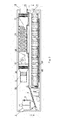
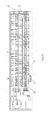
- the air-drying mechanism includes a housing, an axise, blades 4 and an engine, wherein the output shaft of the engine connects with the axise, wherein the engine drives the axise rotating slowly, wherein the blades 4 are regularly set on the axise along the advancing direction of the sludge and have the function of overturning, crushing and forwarding the materials, wherein the dosing mechanism connects with the beginning end of the air-drying mechanism.
- the dosing mechanism connects with the beginning end of the first air-drying mechanism 5, while the terminal end thereof communicates with the beginning end of the second air-drying mechanism 8 through a communicating channel 7, with a discharge port 21 arranged above the communicating channel 7, and the terminal end of the second air-drying mechanism 8 communicates with the beginning end of the first air-drying mechanism 5 so that a loop configuration is formed.
- the dosing mechanism includes or consists of a sludge storage container 2 and a dosing screw transporter 3 wherein the dosing screw transporter 3 is under the sludge storage container 2.
- the sludge is fed into the sludge storage container 2 via the inlet 1, and is transported via the dosing screw transporter 3 to the beginning end of the first air-drying mechanism 5.
- the dosing amount of the sludge is determined by the rotate speed of the dosing screw transporter 3.
- a dried sludge with a water content of 5-35% is transported within the device for air-drying sludge via a dosing screw transporter 10.
- the dosing amount of the dried sludge is determined by the rotate speed of the dosing screw transporter 10.
- the dehumidifying and heating mechanism includes a dehumidifying cool exchanger 12, a tail gas heat exchanger 13, a dehumidifying heat exchanger 16, an air warmer 17, a blower 15 and a refrigeration compressor14, wherein an air inlet 11 connects with the dehumidifying cool exchanger 12, the dehumidifying cool exchanger 12 connects with the tail gas heat exchanger 13, the tail gas heat exchanger 13 connects with the dehumidifying heat exchanger 16 via the blower 15, the air warmer 17 is above the dehumidifying heat exchanger 16, and there is a condensate discharging pipe 22 at the bottom of the dehumidifying cool exchanger 12.
- the dehumidifying and heating mechanism is above the first air-drying mechanism 5 wherein the outlet of the air warmer connects through a pipe 19 with the air inlet 20 on the side or bottom of the air-drying mechanism, the exhaust pipe on the top of the air-drying mechanism connects with the inlet manifold of the tail gas heat exchanger, and the outlet manifold of the tail gas heat exchanger connects with a gas collector which has a condensate collecting pipe on the bottom and a tail gas outlet on the top.
- the dehydrated sludge with a water content of 40-85% was fed into the sludge storage container 2 via the inlet 1, and was transported via the dosing screw transporter 3 to the beginning end of the first air-drying mechanism 5.
- the dosing amount of the sludge was determined by the rotate speed of the dosing screw transporter 3.
- a dried sludge with a water content of 5-35% was transported within the device for air-drying sludge via a dosing screw transporter 10.
- the dosing amount of the dried sludge was determined by the rotate speed of the dosing screw transporter 10.
- the wet sludge and the dried sludge was combined, overturned and forwarded at the action of the blades 4.
- the rotate speed of the axis of the first air-drying mechanism 5 was adjustable between 0-30 rpm. Via the heat conducting and mass transferring with the dehumidified and heated air from the air inlet 20, the moisture in the sludge was evaporated. When forwarded to the terminal end of the first air-drying mechanism 5, the sludge had a reduced water content of 20-40% and an appearance of loose particles. Upon the pressure, the sludge at the terminal end of the first air-drying mechanism 5 entered into the beginning end of the second air-drying mechanism 8 through a communicating channel 7. The rotate speed of the axis of the second air-drying mechanism was adjustable between 0-30 rpm.
- the sludge was discharged from the discharge port 21 as sludge product.
- the sludge entering the second air-drying mechanism 8 was overturned and forwarded at the action of the blades 4.
- the sludge was subjected to the heat conducting and mass transferring with the dehumidified and heated air from the bottom of the second air-drying mechanism 8. The moisture in the sludge was further evaporated.
- the sludge When at the terminal end of the second air-drying mechanism, the sludge had a reduced water content of 5-35%, which was transported via the dosing screw transporter 10 to the beginning end of the first air-drying mechanism 5 and combined with the fresh dehydrated sludge with a water content of 40-85% which was fed into the beginning end of the first air-drying mechanism 5. Then the above procedures were circulated.
- the air was distributed through a main manifold 18 into the communicating pipe 19 and blown into the first and second air-drying mechanism.
- the dehumidified and heated air was subjected to the heat conducting and mass transferring with the sludge, which makes the moisture in the sludge evaporated.
- the tail gas was collected by a gas collecting port over the air-drying mechanism and cooled in the tail gas heat exchanger 13, with the condensate was discharged from a condensate of the tail gas discharging pipe 24 and the cooled tail gas was emitted from a tail gas emitting pipe 23.
Landscapes
- Engineering & Computer Science (AREA)
- Mechanical Engineering (AREA)
- General Engineering & Computer Science (AREA)
- Life Sciences & Earth Sciences (AREA)
- Hydrology & Water Resources (AREA)
- Environmental & Geological Engineering (AREA)
- Water Supply & Treatment (AREA)
- Chemical & Material Sciences (AREA)
- Organic Chemistry (AREA)
- Sustainable Development (AREA)
- Drying Of Solid Materials (AREA)
- Treatment Of Sludge (AREA)
Abstract
Description
- This invention generally belongs to the field of sludge treating device. More particularly, it provides a device for air-drying sludge which is capable of drying sewage sludge with low energy consumption.
- Municipal waste water treatment creates sewage sludge in large amounts. Generally, the municipal waste water treatment plant concentrates and dehydrates the sewage sludge to get a dehydrated sludge having a water content of 80% which is transported to other places for further treatments. To facilitate the reduction and reclamation of the dehydrated sludge, it is generally subjected to drying treatment at first.
- The commonly used methods for drying sludge include drying in a fluid bed dryer, drying in a multilayer disc drier, film drying, drying in a paddle dryer, and belt drying. The dehydrated sludge is dried directly or indirectly. In the actual drying process, the following problems may occur: (1) the inner parts of the drying device are badly worn, leading to high frequency of the device failure; (2) meddle or high temperature is used for drying, leading to high energy consumption; (3) the treatment of tail gases following the drying is complicated, leading to a high cost; and (4) there is a fair possibility of dust explosions and fires, leading to high dangers.
- An object of the present invention is to overcome the deficiencies of the above mentioned process for drying sludge by providing a device for air-drying sludge which has lower energy consumption, less pollution from tail gases, smaller apparatus investment, more stable operation and higher safety.
- This invention embodies as a device for air-drying sludge comprising at least one air-drying mechanism, a dosing mechanism, and a dehumidifying and heating mechanism.
- The air-drying mechanism includes an axise, blades and an engine, wherein the output shaft of the engine connects with the axise, wherein the engine drives the axise rotating slowly, wherein the blades are regularly set on the axise according to the advancing direction of the sludge and have the function of overturning, crushing and forwarding of materials, and wherein the dosing mechanism connects with the beginning end of the air-drying mechanism.
- There are two air-drying mechanisms, wherein the dosing mechanism connects with the beginning end of the first air-drying mechanism, while the terminal end thereof communicates with the beginning end of the second air-drying mechanism, with a discharge port arranged above the communicating position, and the terminal end of the second air-drying mechanism communicates with the beginning end of the first air-drying mechanism so that a loop configuration is formed.
- The dehumidifying and heating mechanism includes a dehumidifying cool exchanger, a tail gas heat exchanger, a dehumidifying heat exchanger, an air warmer, a blower and a refrigeration compressor, wherein an air inlet connects with the dehumidifying cool exchanger, the dehumidifying cool exchanger connects with the tail gas heat exchanger, the tail gas heat exchanger connects with the dehumidifying heat exchanger via the blower, the dehumidifying heat exchanger connects with the air warmer, and there is a condensate discharging pipe at the lower part of the dehumidifying cool exchanger.
- The dehumidifying and heating mechanism is set above the air-drying mechanism, wherein the outlet of the air warmer connects with the air inlet of the air-drying mechanism through a pipe, wherein exhaust pipe on the top of the air-drying mechanism connects with the inlet manifold of the tail gas heat exchanger, and wherein the outlet manifold of the tail gas heat exchanger connects with a gas collector which has a condensate collecting pipe on the bottom and a tail gas outlet on the top.
- The dosing mechanism includes a sludge storage container and a dosing screw transporter wherein the dosing screw transporter is under the sludge storage container.
- Compared to prior art technologies, this invention has following advantages: firstly, the dynamic operation has high stability, allowing an automatic operation. Secondly, the dehumidifying and heating mechanism includes energy recovery devices, making the drying process high efficiency but low energy consumption. Thirdly, the detention time of the sludge in the air-drying device is adjustable, making the water content of the resulting materials adjustable. Fourthly, tail gases are condensed to discharge the condensate before emitting, reducing the cost for further treating the tail gases. Fifthly, the resulting sludge is in the form of loose particles, leading to no anaerobic odor during the long time storage and making them easier for reclamation.
-
-
Figure 1 is a schematic flowchart illustrating a device for air-drying sludge in accordance with this invention. -
Figure 2 is a right side view of the structure of a device for air-drying sludge in accordance with this invention. -
Figure 3 is a front view of the structure of a device for air-drying sludge in accordance with this invention. -
Figure 4 is an illustration of the structure of the cross section at A-A of a device for air-drying sludge in accordance with this invention. - This invention is described in the following section of this specification by making reference to the drawing figures and the embodiments.
- As showed in
figures 1-4 , a device for air-drying sludge includes at least one air-drying mechanism, a dosing mechanism and a dehumidifying and heating mechanism. The air-drying mechanism includes a housing, an axise, blades 4 and an engine, wherein the output shaft of the engine connects with the axise, wherein the engine drives the axise rotating slowly, wherein the blades 4 are regularly set on the axise along the advancing direction of the sludge and have the function of overturning, crushing and forwarding the materials, wherein the dosing mechanism connects with the beginning end of the air-drying mechanism. There are two the air-drying mechanisms, wherein the dosing mechanism connects with the beginning end of the first air-drying mechanism 5, while the terminal end thereof communicates with the beginning end of the second air-drying mechanism 8 through a communicatingchannel 7, with adischarge port 21 arranged above the communicatingchannel 7, and the terminal end of the second air-drying mechanism 8 communicates with the beginning end of the first air-drying mechanism 5 so that a loop configuration is formed. - The dosing mechanism includes or consists of a sludge storage container 2 and a
dosing screw transporter 3 wherein thedosing screw transporter 3 is under the sludge storage container 2. The sludge is fed into the sludge storage container 2 via theinlet 1, and is transported via thedosing screw transporter 3 to the beginning end of the first air-drying mechanism 5. The dosing amount of the sludge is determined by the rotate speed of thedosing screw transporter 3. A dried sludge with a water content of 5-35% is transported within the device for air-drying sludge via adosing screw transporter 10. The dosing amount of the dried sludge is determined by the rotate speed of thedosing screw transporter 10. - The dehumidifying and heating mechanism includes a dehumidifying
cool exchanger 12, a tailgas heat exchanger 13, adehumidifying heat exchanger 16, anair warmer 17, ablower 15 and a refrigeration compressor14, wherein anair inlet 11 connects with the dehumidifyingcool exchanger 12, the dehumidifyingcool exchanger 12 connects with the tailgas heat exchanger 13, the tailgas heat exchanger 13 connects with thedehumidifying heat exchanger 16 via theblower 15, the air warmer 17 is above thedehumidifying heat exchanger 16, and there is acondensate discharging pipe 22 at the bottom of the dehumidifyingcool exchanger 12. The dehumidifying and heating mechanism is above the first air-drying mechanism 5 wherein the outlet of the air warmer connects through apipe 19 with theair inlet 20 on the side or bottom of the air-drying mechanism, the exhaust pipe on the top of the air-drying mechanism connects with the inlet manifold of the tail gas heat exchanger, and the outlet manifold of the tail gas heat exchanger connects with a gas collector which has a condensate collecting pipe on the bottom and a tail gas outlet on the top. - The dehydrated sludge with a water content of 40-85% was fed into the sludge storage container 2 via the
inlet 1, and was transported via thedosing screw transporter 3 to the beginning end of the first air-drying mechanism 5. The dosing amount of the sludge was determined by the rotate speed of thedosing screw transporter 3. A dried sludge with a water content of 5-35% was transported within the device for air-drying sludge via adosing screw transporter 10. The dosing amount of the dried sludge was determined by the rotate speed of thedosing screw transporter 10. The wet sludge and the dried sludge was combined, overturned and forwarded at the action of the blades 4. The rotate speed of the axis of the first air-drying mechanism 5 was adjustable between 0-30 rpm. Via the heat conducting and mass transferring with the dehumidified and heated air from theair inlet 20, the moisture in the sludge was evaporated. When forwarded to the terminal end of the first air-drying mechanism 5, the sludge had a reduced water content of 20-40% and an appearance of loose particles. Upon the pressure, the sludge at the terminal end of the first air-drying mechanism 5 entered into the beginning end of the second air-drying mechanism 8 through a communicatingchannel 7. The rotate speed of the axis of the second air-drying mechanism was adjustable between 0-30 rpm. When the level of the materials in the second air-drying mechanism 8 was over the lower side of thedischarge port 21, the sludge was discharged from thedischarge port 21 as sludge product. The sludge entering the second air-drying mechanism 8 was overturned and forwarded at the action of the blades 4. At the same time, the sludge was subjected to the heat conducting and mass transferring with the dehumidified and heated air from the bottom of the second air-drying mechanism 8. The moisture in the sludge was further evaporated. When at the terminal end of the second air-drying mechanism, the sludge had a reduced water content of 5-35%, which was transported via thedosing screw transporter 10 to the beginning end of the first air-drying mechanism 5 and combined with the fresh dehydrated sludge with a water content of 40-85% which was fed into the beginning end of the first air-drying mechanism 5. Then the above procedures were circulated. - Upon the action of the
blower 15, air were sucked into the dehumidifying and heating mechanism and cooled in the dehumidifyingcool exchanger 12, with the condensate was discharged from thecondensate discharging pipe 22. By passing the dehumidified air through the outer space of the tailgas heat exchanger 13 and the tail gas through the inner tubes of the tailgas heat exchanger 13, the air and the tail gas were indirectly heat-exchanged to recover the heat of the tail gas. Then, the air was passed into thedehumidifying heat exchanger 16 to recover the heat. Next, the air was passed into the air warmer 17 to increase the temperature thereof to 20-200°C. Finally, the air was distributed through amain manifold 18 into the communicatingpipe 19 and blown into the first and second air-drying mechanism. The dehumidified and heated air was subjected to the heat conducting and mass transferring with the sludge, which makes the moisture in the sludge evaporated. The tail gas was collected by a gas collecting port over the air-drying mechanism and cooled in the tailgas heat exchanger 13, with the condensate was discharged from a condensate of the tailgas discharging pipe 24 and the cooled tail gas was emitted from a tailgas emitting pipe 23. - It should be emphasized that the above-described embodiments is not to be considered as limiting. Many variations and modifications may be made by those skilled persons in the art to the above-described embodiments of the invention without departing substantially from the spirit and principles of the invention. All such modifications and variations are intended to be included herein within the scope of this disclosure and the present invention and protected by the following claims.
Claims (6)
- A device for air-drying sludge comprising at least one air-drying mechanism, a dosing mechanism and a dehumidifying and heating mechanism, wherein the air-drying mechanism includes an axise, blades and an engine, wherein the output shaft of the engine connects with the axise, wherein the blades are set on the axise, and wherein the dosing mechanism connects with the beginning end of the air-drying mechanism.
- A device as described in claim 1, wherein there are two air-drying mechanisms, wherein the dosing mechanism connects with the beginning end of the first air-drying mechanism, while the terminal end thereof communicates with the beginning end of the second air-drying mechanism, with a discharge port arranged above the communicating position, and the terminal end of the second air-drying mechanism communicates with the beginning end of the first air-drying mechanism so that a loop configuration is formed.
- A device as described in claim 2, wherein the dehumidifying and heating mechanism includes a dehumidifying cool exchanger, a tail gas heat exchanger, a dehumidifying heat exchanger, an air warmer, a blower and a refrigeration compressor, wherein an air inlet connects with the dehumidifying cool exchanger, the dehumidifying cool exchanger connects with the tail gas heat exchanger, the tail gas heat exchanger connects with the dehumidifying heat exchanger via the blower, the dehumidifying heat exchanger connects with the air warmer, and there is a condensate discharging pipe at the lower part of the dehumidifying cool exchanger.
- A device as described in claim 3, wherein the dehumidifying and heating mechanism is above the air-drying mechanism, wherein the outlet of the air warmer connects with the air inlet of the air-drying mechanism through a pipe, wherein exhaust pipe on the top of the air-drying mechanism connects with the inlet manifold of the tail gas heat exchanger, and wherein the outlet manifold of the tail gas heat exchanger connects with a gas collector which has a condensate collecting pipe on the bottom and a tail gas outlet on the top.
- A device as described in claim 1, wherein the dosing mechanism includes a sludge storage container and a dosing screw transporter wherein the dosing screw transporter is under the sludge storage container.
- A device as described in claim 1, 2 or 3, wherein the rotate speed of the axis of the air-drying mechanism is between 0-30 rpm.
Applications Claiming Priority (2)
| Application Number | Priority Date | Filing Date | Title |
|---|---|---|---|
| CN2010201129661U CN201574114U (en) | 2010-02-05 | 2010-02-05 | A sludge drying device |
| PCT/CN2010/000283 WO2011094904A1 (en) | 2010-02-05 | 2010-03-08 | Air-drying device for sludge |
Publications (2)
| Publication Number | Publication Date |
|---|---|
| EP2562140A1 true EP2562140A1 (en) | 2013-02-27 |
| EP2562140A4 EP2562140A4 (en) | 2013-12-04 |
Family
ID=42693990
Family Applications (1)
| Application Number | Title | Priority Date | Filing Date |
|---|---|---|---|
| EP10844989.3A Withdrawn EP2562140A4 (en) | 2010-02-05 | 2010-03-08 | AIR DRYING DEVICE FOR SLUDGE |
Country Status (6)
| Country | Link |
|---|---|
| US (1) | US9021716B2 (en) |
| EP (1) | EP2562140A4 (en) |
| JP (1) | JP3181483U (en) |
| KR (1) | KR200478208Y1 (en) |
| CN (1) | CN201574114U (en) |
| WO (1) | WO2011094904A1 (en) |
Families Citing this family (12)
| Publication number | Priority date | Publication date | Assignee | Title |
|---|---|---|---|---|
| CN201574114U (en) * | 2010-02-05 | 2010-09-08 | 广州普得环保设备有限公司 | A sludge drying device |
| CN102303944B (en) | 2011-08-22 | 2014-08-27 | 广州新致晟环保科技机械设备有限公司 | Method for re-treating dewatered sludge |
| CN102815804A (en) * | 2012-08-28 | 2012-12-12 | 广西大都混凝土集团有限公司 | Separating equipment for waste water and waste residue of concrete |
| US8869420B1 (en) * | 2012-11-19 | 2014-10-28 | Mousa Mohammad Nazhad | Energy-efficient process and apparatus for drying feedstock |
| CN103922559B (en) * | 2014-05-06 | 2016-03-02 | 王兢 | Sludge air drying device |
| CN105478449A (en) * | 2016-01-07 | 2016-04-13 | 浙江泰来环保科技有限公司 | Garbage incineration fly ash curing system |
| CN108168215B (en) * | 2017-12-27 | 2024-04-16 | 泽玛克(上海)环保能源科技有限公司 | Feeding equipment and dryer |
| KR102069308B1 (en) * | 2018-10-02 | 2020-01-22 | 주식회사 이열알앤디 | Dried air supply apparatus for sludge fueling system |
| KR102069317B1 (en) * | 2018-10-02 | 2020-01-22 | 주식회사 이열알앤디 | Sludge fueling system |
| CN109553271A (en) * | 2019-01-12 | 2019-04-02 | 北京市市政二建设工程有限责任公司 | A kind of sludge drying treatment equipment |
| CN114111304A (en) * | 2022-01-28 | 2022-03-01 | 东营市华兴化工有限责任公司 | Polyacrylamide drying device |
| CN119687668A (en) * | 2025-02-24 | 2025-03-25 | 江苏永盛生物科技有限公司 | Continuous chicken powder drying device |
Family Cites Families (27)
| Publication number | Priority date | Publication date | Assignee | Title |
|---|---|---|---|---|
| IT1194684B (en) * | 1980-09-05 | 1988-09-22 | Ivo Coppa | PROCESS AND PLANT FOR DRYING PRODUCTS AND MATERIALS SUCH AS WOOD |
| US4330946A (en) * | 1980-09-23 | 1982-05-25 | Ralph S. Tillitt | High efficiency material drying |
| EP0343431B1 (en) * | 1988-05-24 | 1993-08-25 | Siemens Aktiengesellschaft | Process and apparatus for sewage sludge drying |
| US5216821A (en) | 1991-04-10 | 1993-06-08 | Remediation Technologies, Incorporated | System and method for removing a volatile component from a matrix |
| US5220733A (en) * | 1991-11-14 | 1993-06-22 | 21St Century Design Inc. | Modular radiant plate drying apparatus |
| US5343632A (en) * | 1992-04-10 | 1994-09-06 | Advanced Dryer Systems, Inc. | Closed-loop drying process and system |
| US5245762A (en) * | 1992-08-24 | 1993-09-21 | Hartis Dennis R | Sludge drying apparatus and method |
| US5318184A (en) | 1992-09-10 | 1994-06-07 | Georg Krebs | Sludge drying system |
| US5680711A (en) * | 1996-03-01 | 1997-10-28 | Moratalla; Jose | Thermal processing system |
| JPH1028998A (en) | 1996-07-12 | 1998-02-03 | Ishigaki:Kk | Granulation method of sludge cake |
| AT405644B (en) | 1996-09-26 | 1999-10-25 | Andritz Patentverwaltung | METHOD FOR INDIRECTLY HEATED DRYING OF GOODS, ESPECIALLY SLUDGE |
| KR0177364B1 (en) * | 1996-11-07 | 1999-04-01 | 김학재 | Organic and inorganic sludge drying method and apparatus |
| KR100259215B1 (en) | 1997-02-06 | 2000-06-15 | 진춘식 | Incinerator for excrement material |
| AU7420298A (en) * | 1997-05-09 | 1998-12-08 | Solutions Mabarex Inc. | Method for reducing moisture content |
| CA2289444C (en) | 1997-05-09 | 2007-12-18 | Solutions Mabarex Inc. | Method for reducing moisture content |
| US6209223B1 (en) * | 1998-12-08 | 2001-04-03 | Advanced Dryer Systems, Inc. | Grain drying system with high efficiency dehumidifier and modular drying bin |
| US6094835A (en) * | 1998-12-14 | 2000-08-01 | University Of Central Florida | Heat pump dryer with desciccant enhanced moisture removal |
| KR100361909B1 (en) | 1999-08-03 | 2002-11-23 | 김애자 | The Drying Device for Sludge |
| JP2004093018A (en) * | 2002-08-30 | 2004-03-25 | Mitsubishi Heavy Ind Ltd | Incineration system |
| US20040212555A1 (en) | 2003-04-23 | 2004-10-28 | Falco Mark A. | Portable electronic device with integrated display and camera and method therefore |
| US7819931B2 (en) * | 2003-08-22 | 2010-10-26 | Morris Peltier | Soil mediums and alternative fuel mediums, apparatus and methods of their production and uses thereof |
| NO20050189A (en) | 2005-01-13 | 2006-02-20 | Hammer Asbjoern | Device for drying material |
| NZ541426A (en) * | 2005-07-25 | 2008-06-30 | Flo Dry Engineering Ltd | Method and apparatus for drying |
| CN101224912B (en) | 2008-01-25 | 2011-03-23 | 广州普得环保设备有限公司 | Method for drying sludge |
| CN101585653B (en) | 2008-10-20 | 2011-07-20 | 中国华电工程(集团)有限公司 | Method and device for reutilizing waste heat in sludge drying system |
| CN101618931B (en) | 2009-07-28 | 2011-06-29 | 清华大学 | Mud drying and incinerating integrated system and use method thereof |
| CN201574114U (en) | 2010-02-05 | 2010-09-08 | 广州普得环保设备有限公司 | A sludge drying device |
-
2010
- 2010-02-05 CN CN2010201129661U patent/CN201574114U/en not_active Expired - Lifetime
- 2010-03-08 KR KR2020127000043U patent/KR200478208Y1/en not_active Expired - Lifetime
- 2010-03-08 EP EP10844989.3A patent/EP2562140A4/en not_active Withdrawn
- 2010-03-08 WO PCT/CN2010/000283 patent/WO2011094904A1/en not_active Ceased
- 2010-03-08 US US13/576,992 patent/US9021716B2/en active Active
- 2010-03-08 JP JP2012600065U patent/JP3181483U/en not_active Expired - Lifetime
Also Published As
| Publication number | Publication date |
|---|---|
| JP3181483U (en) | 2013-02-14 |
| KR200478208Y1 (en) | 2015-09-08 |
| KR20120007709U (en) | 2012-11-07 |
| CN201574114U (en) | 2010-09-08 |
| US20130167394A1 (en) | 2013-07-04 |
| EP2562140A4 (en) | 2013-12-04 |
| US9021716B2 (en) | 2015-05-05 |
| WO2011094904A1 (en) | 2011-08-11 |
Similar Documents
| Publication | Publication Date | Title |
|---|---|---|
| US9021716B2 (en) | Devices for air-drying sludge | |
| CN201637228U (en) | Novel superheated steam drying cooling system | |
| CN101731327B (en) | Centralized drying system of high-humidity grain and drying method thereof | |
| CN110127984B (en) | Sludge low-temperature heat pump drying equipment | |
| WO2011035459A1 (en) | Method and apparatus for aerobically air-drying sludge filter cakes | |
| CN106430901A (en) | Moisture discharge and drying system for sludge | |
| CN104729269A (en) | Medicine and edible material processing device | |
| CN104098242B (en) | Sewage sludge advanced treatment method | |
| CN111018299B (en) | A negative pressure heat pump closed sludge drying system | |
| CN211601490U (en) | Heat pump type low-temperature coal slime drying system based on low-temperature heat pipe | |
| CN101830624B (en) | System and process for drying sludge blades | |
| CN201694934U (en) | Sludge blade drying system | |
| CN205850536U (en) | A kind of tower tail gas treatment device | |
| CN115259620A (en) | Sludge low-temperature belt type drying machine with stable drying performance | |
| CN113137610A (en) | Household garbage drying system and method | |
| CN107289742A (en) | A kind of tiny structure low temperature drying device and its drying process | |
| CN201517065U (en) | Sludge filter cake low-temperature air dry device | |
| CN206345771U (en) | A kind of sludge hydrofuge anhydration system | |
| CN206033537U (en) | Heat pump drying system | |
| CN106931763B (en) | Intelligent air energy shrimp shell dryer | |
| CN212692418U (en) | Solar heat pump and microwave multi-energy complementary combined drying and sterilizing equipment | |
| CN207779045U (en) | Use in waste water treatment sludge drying mechanism in a kind of fur manufacturing | |
| CN207478270U (en) | Drying process system | |
| CN106996689B (en) | How to use the intelligent air energy shrimp shell dryer | |
| KR100651040B1 (en) | Livestock Manure Treatment System |
Legal Events
| Date | Code | Title | Description |
|---|---|---|---|
| PUAI | Public reference made under article 153(3) epc to a published international application that has entered the european phase |
Free format text: ORIGINAL CODE: 0009012 |
|
| 17P | Request for examination filed |
Effective date: 20120903 |
|
| AK | Designated contracting states |
Kind code of ref document: A1 Designated state(s): AT BE BG CH CY CZ DE DK EE ES FI FR GB GR HR HU IE IS IT LI LT LU LV MC MK MT NL NO PL PT RO SE SI SK SM TR |
|
| DAX | Request for extension of the european patent (deleted) | ||
| A4 | Supplementary search report drawn up and despatched |
Effective date: 20131031 |
|
| RIC1 | Information provided on ipc code assigned before grant |
Ipc: C02F 11/12 20060101AFI20131025BHEP |
|
| RAP1 | Party data changed (applicant data changed or rights of an application transferred) |
Owner name: GUANGZHOU NEW EXTEND RISING ENVIRONMENTAL PROTECTI |
|
| 17Q | First examination report despatched |
Effective date: 20160413 |
|
| STAA | Information on the status of an ep patent application or granted ep patent |
Free format text: STATUS: THE APPLICATION IS DEEMED TO BE WITHDRAWN |
|
| 18D | Application deemed to be withdrawn |
Effective date: 20160624 |