EP2562101A1 - A capsule for use in a beverage preparation machine - Google Patents
A capsule for use in a beverage preparation machine Download PDFInfo
- Publication number
- EP2562101A1 EP2562101A1 EP11178246A EP11178246A EP2562101A1 EP 2562101 A1 EP2562101 A1 EP 2562101A1 EP 11178246 A EP11178246 A EP 11178246A EP 11178246 A EP11178246 A EP 11178246A EP 2562101 A1 EP2562101 A1 EP 2562101A1
- Authority
- EP
- European Patent Office
- Prior art keywords
- capsule
- top membrane
- liquid
- elastic material
- membrane
- Prior art date
- Legal status (The legal status is an assumption and is not a legal conclusion. Google has not performed a legal analysis and makes no representation as to the accuracy of the status listed.)
- Withdrawn
Links
- 239000002775 capsule Substances 0.000 title claims abstract description 88
- 235000013361 beverage Nutrition 0.000 title claims abstract description 21
- 238000002360 preparation method Methods 0.000 title claims abstract description 16
- 239000012528 membrane Substances 0.000 claims abstract description 68
- 238000002347 injection Methods 0.000 claims abstract description 41
- 239000007924 injection Substances 0.000 claims abstract description 41
- 239000007788 liquid Substances 0.000 claims abstract description 36
- 239000012530 fluid Substances 0.000 claims abstract description 29
- 239000013013 elastic material Substances 0.000 claims abstract description 21
- 238000000605 extraction Methods 0.000 claims abstract description 8
- 230000000694 effects Effects 0.000 claims abstract description 7
- 239000000463 material Substances 0.000 claims abstract description 7
- 235000013305 food Nutrition 0.000 claims abstract description 6
- 239000010410 layer Substances 0.000 claims description 23
- 229920001296 polysiloxane Polymers 0.000 claims description 16
- XAGFODPZIPBFFR-UHFFFAOYSA-N aluminium Chemical compound [Al] XAGFODPZIPBFFR-UHFFFAOYSA-N 0.000 claims description 7
- 229910052782 aluminium Inorganic materials 0.000 claims description 7
- 239000004411 aluminium Substances 0.000 claims description 5
- 238000010438 heat treatment Methods 0.000 claims description 4
- 238000003302 UV-light treatment Methods 0.000 claims description 3
- 229920001971 elastomer Polymers 0.000 claims description 3
- 239000000806 elastomer Substances 0.000 claims description 3
- 239000012943 hotmelt Substances 0.000 claims description 3
- 239000002356 single layer Substances 0.000 claims description 3
- 239000007791 liquid phase Substances 0.000 claims description 2
- 238000002844 melting Methods 0.000 claims description 2
- 230000008018 melting Effects 0.000 claims description 2
- 239000004033 plastic Substances 0.000 claims description 2
- 229920003023 plastic Polymers 0.000 claims description 2
- 229920000642 polymer Polymers 0.000 claims 1
- 235000013353 coffee beverage Nutrition 0.000 description 12
- XLYOFNOQVPJJNP-UHFFFAOYSA-N water Substances O XLYOFNOQVPJJNP-UHFFFAOYSA-N 0.000 description 12
- 239000004615 ingredient Substances 0.000 description 8
- PPBRXRYQALVLMV-UHFFFAOYSA-N Styrene Chemical compound C=CC1=CC=CC=C1 PPBRXRYQALVLMV-UHFFFAOYSA-N 0.000 description 4
- 239000000126 substance Substances 0.000 description 4
- 241000283153 Cetacea Species 0.000 description 3
- -1 Ethylbutylene Chemical group 0.000 description 3
- 238000012986 modification Methods 0.000 description 3
- 230000004048 modification Effects 0.000 description 3
- 229920000219 Ethylene vinyl alcohol Polymers 0.000 description 2
- 238000004090 dissolution Methods 0.000 description 2
- 239000004715 ethylene vinyl alcohol Substances 0.000 description 2
- 239000003292 glue Substances 0.000 description 2
- RZXDTJIXPSCHCI-UHFFFAOYSA-N hexa-1,5-diene-2,5-diol Chemical compound OC(=C)CCC(O)=C RZXDTJIXPSCHCI-UHFFFAOYSA-N 0.000 description 2
- 229910052710 silicon Inorganic materials 0.000 description 2
- 239000010703 silicon Substances 0.000 description 2
- 229920002379 silicone rubber Polymers 0.000 description 2
- 241000894006 Bacteria Species 0.000 description 1
- 239000004944 Liquid Silicone Rubber Substances 0.000 description 1
- 239000004698 Polyethylene Substances 0.000 description 1
- 239000004743 Polypropylene Substances 0.000 description 1
- 241001122767 Theaceae Species 0.000 description 1
- 239000000853 adhesive Substances 0.000 description 1
- 230000001070 adhesive effect Effects 0.000 description 1
- 238000004140 cleaning Methods 0.000 description 1
- 230000003749 cleanliness Effects 0.000 description 1
- 239000011248 coating agent Substances 0.000 description 1
- 238000000576 coating method Methods 0.000 description 1
- 238000013461 design Methods 0.000 description 1
- 230000003467 diminishing effect Effects 0.000 description 1
- 230000009977 dual effect Effects 0.000 description 1
- 235000015114 espresso Nutrition 0.000 description 1
- 238000001802 infusion Methods 0.000 description 1
- 238000009533 lab test Methods 0.000 description 1
- 238000003475 lamination Methods 0.000 description 1
- 238000000034 method Methods 0.000 description 1
- 239000000123 paper Substances 0.000 description 1
- 230000002572 peristaltic effect Effects 0.000 description 1
- 229920000573 polyethylene Polymers 0.000 description 1
- 229920001155 polypropylene Polymers 0.000 description 1
- 239000000843 powder Substances 0.000 description 1
- 239000004945 silicone rubber Substances 0.000 description 1
- 239000007921 spray Substances 0.000 description 1
- 229910001220 stainless steel Inorganic materials 0.000 description 1
- 239000010935 stainless steel Substances 0.000 description 1
- 238000012360 testing method Methods 0.000 description 1
- 229920002725 thermoplastic elastomer Polymers 0.000 description 1
Images


Classifications
-
- B—PERFORMING OPERATIONS; TRANSPORTING
- B65—CONVEYING; PACKING; STORING; HANDLING THIN OR FILAMENTARY MATERIAL
- B65D—CONTAINERS FOR STORAGE OR TRANSPORT OF ARTICLES OR MATERIALS, e.g. BAGS, BARRELS, BOTTLES, BOXES, CANS, CARTONS, CRATES, DRUMS, JARS, TANKS, HOPPERS, FORWARDING CONTAINERS; ACCESSORIES, CLOSURES, OR FITTINGS THEREFOR; PACKAGING ELEMENTS; PACKAGES
- B65D85/00—Containers, packaging elements or packages, specially adapted for particular articles or materials
- B65D85/70—Containers, packaging elements or packages, specially adapted for particular articles or materials for materials not otherwise provided for
- B65D85/804—Disposable containers or packages with contents which are mixed, infused or dissolved in situ, i.e. without having been previously removed from the package
- B65D85/8043—Packages adapted to allow liquid to pass through the contents
-
- B—PERFORMING OPERATIONS; TRANSPORTING
- B65—CONVEYING; PACKING; STORING; HANDLING THIN OR FILAMENTARY MATERIAL
- B65D—CONTAINERS FOR STORAGE OR TRANSPORT OF ARTICLES OR MATERIALS, e.g. BAGS, BARRELS, BOTTLES, BOXES, CANS, CARTONS, CRATES, DRUMS, JARS, TANKS, HOPPERS, FORWARDING CONTAINERS; ACCESSORIES, CLOSURES, OR FITTINGS THEREFOR; PACKAGING ELEMENTS; PACKAGES
- B65D85/00—Containers, packaging elements or packages, specially adapted for particular articles or materials
- B65D85/70—Containers, packaging elements or packages, specially adapted for particular articles or materials for materials not otherwise provided for
- B65D85/804—Disposable containers or packages with contents which are mixed, infused or dissolved in situ, i.e. without having been previously removed from the package
-
- A—HUMAN NECESSITIES
- A47—FURNITURE; DOMESTIC ARTICLES OR APPLIANCES; COFFEE MILLS; SPICE MILLS; SUCTION CLEANERS IN GENERAL
- A47J—KITCHEN EQUIPMENT; COFFEE MILLS; SPICE MILLS; APPARATUS FOR MAKING BEVERAGES
- A47J31/00—Apparatus for making beverages
-
- A—HUMAN NECESSITIES
- A47—FURNITURE; DOMESTIC ARTICLES OR APPLIANCES; COFFEE MILLS; SPICE MILLS; SUCTION CLEANERS IN GENERAL
- A47J—KITCHEN EQUIPMENT; COFFEE MILLS; SPICE MILLS; APPARATUS FOR MAKING BEVERAGES
- A47J31/00—Apparatus for making beverages
- A47J31/40—Beverage-making apparatus with dispensing means for adding a measured quantity of ingredients, e.g. coffee, water, sugar, cocoa, milk, tea
- A47J31/407—Beverage-making apparatus with dispensing means for adding a measured quantity of ingredients, e.g. coffee, water, sugar, cocoa, milk, tea with ingredient-containing cartridges; Cartridge-perforating means
Definitions
- the present invention concerns a capsule for use in a beverage preparation machine, whose top pierceable membrane is self reclosable.
- Beverage preparation machines are well known in the food science and consumer goods area. Such machines allow a consumer to prepare at home a given type of beverage, for instance a coffee-based beverage, e.g. an espresso or a brew-like coffee cup.
- a coffee-based beverage e.g. an espresso or a brew-like coffee cup.
- beverage preparation machines for in-home beverage preparation comprise a system made of a machine which can accommodate portioned ingredients for the preparation of the beverage.
- Such portions can be soft pods or pads, or sachets, but more and more systems use semi-rigid or rigid portions such as rigid pods or capsules.
- the beverage machine of the invention is a beverage preparation machine working a rigid capsule.
- the machine comprises a receptacle for accommodating said capsule and a fluid injection system for injecting a fluid, preferably water, under pressure into said capsule.
- a fluid preferably water
- Water injected under pressure in the capsule, for the preparation of a coffee beverage according to the present invention is preferably hot, that is to say at a temperature above 70°C. However, in some particular instances, it might also be at ambient temperature.
- the pressure inside the capsule chamber during extraction and/or dissolution of the capsule contents is typically about 1 to 8 bar for dissolution products, 2 to 12 bar for extraction of roast and ground coffee.
- Such a preparation process differs a lot from the so-called "brewing" process of beverage preparation - particularly for tea and coffee, in that brewing involves a long time of infusion of the ingredient by a fluid (e.g. hot water), whereas the beverage preparation process allows a consumer to prepare a beverage, for instance coffee within a few seconds.
- the principle of extracting and/or dissolving the contents of a closed capsule under pressure is known and consists typically of confining the capsule in a receptacle of a machine, injecting a quantity of pressurized water into the capsule, generally after piercing a face of the capsule with a piercing injection element such as a fluid injection needle mounted on the machine, so as to create a pressurized environment inside the capsule either to extract the substance or dissolve it, and then release the extracted substance or the dissolved substance through the capsule.
- a piercing injection element such as a fluid injection needle mounted on the machine
- the machine comprises a receptacle for the capsule and a perforation and injection element made in the form of a hollow needle comprising in its distal region one or more liquid injection orifices.
- the needle has a dual function in that it opens the top portion of the capsule on the one hand, and that it forms the water inlet channel into the capsule on the other hand.
- the machine further comprises a fluid tank - in most cases this fluid is water - for storing the fluid that is used to dissolve and/or infuse and/or extract under pressure the ingredient(s) contained in the capsule.
- the machine comprises a heating element such as a boiler or a heat exchanger, which is able to warm up the water used therein to working temperatures (classically temperatures up to 80-90°C).
- the machine comprises a pump element for circulating the water from the tank to the capsule, optionally though the heating element. The way the water circulates within the machine is selected via a selecting valve means, such as for instance a peristaltic valve of the type described in applicant's European patent application EP 2162653 A1 .
- the beverage to be prepared is coffee
- one interesting way to prepare the said coffee is to provide the consumer with a capsule containing roast and ground coffee powder, which is to be extracted with hot water injected therein.
- capsules comprise typically:
- Capsules of the prior art as illustrated in figure 1 feature a top membrane which is to be pierced by the fluid injection needle of the beverage preparation machine.
- a pressure is built up, which serves as an extraction means for extracting ingredients contained inside the capsule, as described above.
- the capsule compartment In case the capsule contains soluble ingredient to extract, the capsule compartment generally comprises one single portion, and the residual fluid pressure is distributed across the compartment volume.
- the residual pressure P is located in the top portion of the capsule compartment.
- the ingredient to be extracted typically roast and ground coffee "RG”
- RG roast and ground coffee
- a capsule defining a closed chamber for enclosing a mass of soluble and/or extractable food material, for use in a beverage preparation machine, comprising:
- An elastic material suitable for the present invention should have a Young's modulus inferior to 150 GPa.
- the top membrane Due to the elasticity of the material, the top membrane can be pierced easily and deform when the liquid injection means of the machine are moved through. Then, after the liquid has been injected into the capsule, the injection means is removed therefrom and the top membrane closes back in a leaktight manner due to its high elasticity.
- the top membrane is able to withstand a fluid pressure of at least 1 bar, preferably at least 3 bar, more preferably at least 5 bar, after said fluid injection means have been removed therefrom.
- the bottom wall is a pierceable membrane, made of aluminium, paper, plastic, or a combination thereof.
- the liquid injection means of the machine is a liquid injection hollow needle.
- the top membrane comprises one single layer of elastic material (i.e. it is a so-called monolayer membrane).
- the top membrane is a laminate comprising several superimposed layers which are at least partially assembled one to another, so that at least one of the constitutive layers of the laminate is made of an elastic material.
- the lamination in the area where the needle pierces the top membrane is a weaker adhesion in comparison to other regions of the membrane, in order to facilitate the reclosing movement of the elastic layer.
- the top membrane comprises a non elastic film, at least of portion of which is coated with a layer of an elastic material.
- the elastic material is preferably coated onto said film in a liquid phase, which is then solidified by a heat or UV light treatment.
- the top membrane comprises a non elastic film, at least of portion of which is covered with a layer of an elastic material with a glue using "sticker-like" application.
- the top membrane of the capsule is coated at least on a portion of its surface with a layer of silicone that is applied over its melting temperature (i.e. as a liquid form) such that it then solidifies as it cools down onto the membrane onto which it is applied ("hot melt application").
- a layer of silicone that is applied over its melting temperature (i.e. as a liquid form) such that it then solidifies as it cools down onto the membrane onto which it is applied (“hot melt application").
- the elastic material is preferably a food-grade silicon, particularly a liquid mono-component silicon which is set by reaction with the atmospheric humidity (i.e. at ambient temperature).
- examples of elastic materials include but are not limited to for instance: a food-grade thermoplastic elastomer such as SEBS (Styrene Ethylbutylene Styrene), silicone or liquid silicone rubber, or an ethylene vinyl alcohol (EVA) -based hot melt.
- top membrane should be understood as the membrane which is pierced by the fluid injection needle of the machine, as opposed to the “bottom membrane” which should be understood as the membrane located on the opposite side of the capsule.
- bottom membrane should be understood as the membrane located on the opposite side of the capsule.
- the capsule 1 illustrated in figures 3, 4 , 5 and 6 comprises a capsule body defining a closed chamber for enclosing a mass of soluble and/or extractable food material "RG".
- the capsule body comprises in particular:
- the capsule further comprises means adapted to open said chamber by relative engagement with the bottom wall under the effect of the liquid pressure increase in the chamber during injection of said liquid.
- These means comprise an rigid element 6 comprising spikes 7 on its surface turned towards the aluminium membrane 5.
- the rigid element 6 is generally referred to as "pyramid plate”.
- the top membrane surface which is to be pierced by the fluid injection needle comprises an elastic material having a tensile strength higher than 5 MPa, preferably higher than 10 MPa, and an elongation at break superior to 100%, preferably superior to 500%, such that said top membrane recloses in a leaktight manner, after said fluid injection means have been removed therefrom. More precisely, the top membrane is able to withstand a fluid pressure of at least 3 bar after said fluid injection means have been removed therefrom.
- the top membrane 3 is a laminate comprising several superimposed layers 8 which are at least partially assembled one to another, so that at least one of the constitutive layers of the laminate is made of an elastic material.
- the top membrane 3 comprises four superimposed layers.
- the lowermost layer 9 comprises an elastic silicone layer having a tensile strength of about 10 MPa, and an elongation at break of about 700%.
- the first intermediate layer 10 disposed immediately above is made of a polypropylene material (Young's modulus of about 1.5 GPa and yield strength of about 40 MPa).
- the second intermediate layer 11 disposed immediately above is made of an elastic silicone layer having a tensile strength of about 10 MPa, and an elongation at break of about 700%.
- the uppermost layer 12 is made of a polyethylene (Young's modulus of about 0.6 GPa and yield strength of about 35 MPa).
- the top membrane 3 is coated with a ring 13 of silicone deposited as a liquid onto the capsule top membrane surface. More precisely, a portion of the top membrane upper surface is coated with a layer of a silicone elastic material having a tensile strength of about 10 MPa, and an elongation at break of about 700%.
- the layer of silicone is deposited as a liquid and then set at room temperature by using UV light treatment.
- the silicone that is used is food grade.
- the ring 13 has a thickness of between 0.1 and 1 mm, preferably a thickness between 0.3 mm and 0.7 mm. It has width larger than the diameter of the liquid injection needle 4, preferably three times as large as the needle.
- the ring is positioned onto the top membrane 3 in such a way that whatever the rotational position of the capsule in the machine, the needle pierces through the zone of said top membrane which is coated with the silicone ring. It could also be envisaged that the lower surface of the top membrane be coated with an elastic material, however such an embodiment is not preferred as it is considered easier to coat the upper side of said top membrane.
- the top membrane 3 is bonded with a ring of silicone 13.
- the material used for the ring is a silicone elastic material having a tensile strength of about 10 MPa, and an elongation at break of about 700%.
- the ring 13 has a thickness of between 0.1 and 1 mm, preferably a thickness between 0.3 mm and 0.7 mm. It has width larger than the diameter of the liquid injection needle 4, preferably twice as large as the needle.
- the ring is positioned onto the top membrane 3 in such a way that whatever the rotational position of the capsule in the machine, the needle pierces through the zone of said top membrane which is coated with the silicone ring, as illustrated in figure 5 .
- the ring 13 is bonded to the top membrane 4 using a food-grade adhesive.
- a disc of silicone (not illustrated in the drawing) has a diameter of at least twice the diameter of the needle.
- the capsule shape is preferably modified in a non circular shape, in order to provide an orientation of the capsule inside the capsule holder or inside the machine, in such a way that, in operation, the needle pierces through the disc.
- the capsule design or a drawing on the capsule indicates the consumer what is the correct orientation of the capsule inside the capsule holder or inside the machine.
- elastomer such as silicone ⁇ alone or in combination as a layer in a multilayer membrane, or a s coating or ring -, wherein the elastomer layer as a thickness of between 0.1 and 1 mm, preferably a thickness between 0.3 mm and 0.7 mm delivers good results in terms of reclosability and leak tightness, when the internal residual pressure inside the capsule after product preparation is between 0.5 and 5 bar (relative pressure to atmospheric pressure).
- the diameter of the needle was comprised between 0.5 mm and 3 mm, and more precisely between 1.0 mm and 1.6 mm.
- the needle can have 1.5 mm in diameter with a 30° apex cut angle.
- the needle used for the liquid injection in the capsule is stainless steel.
Landscapes
- Engineering & Computer Science (AREA)
- Mechanical Engineering (AREA)
- Apparatus For Making Beverages (AREA)
Abstract
(i) capsule side walls (2),
(ii) a top membrane (3) pierceable by injection means (4) of the machine which are adapted to inject an extraction liquid under pressure inside said chamber, and
(iii) a bottom wall (5)
(iv) means (6, 7) adapted to open said chamber by relative engagement with the bottom wall (5) under the effect of the liquid pressure increase in the chamber during injection of said liquid
characterized in that at least the portion of the top membrane surface which is to be pierced by the fluid injection means (4), comprises an elastic material having a tensile strength higher than 5 MPa, preferably higher than 10 MPa, and an elongation at break superior to 100%, preferably superior to 500%, such that said top membrane (3) recloses in a leaktight manner, after said fluid injection means (4) have been removed therefrom.
Description
- The present invention concerns a capsule for use in a beverage preparation machine, whose top pierceable membrane is self reclosable.
- Beverage preparation machines are well known in the food science and consumer goods area. Such machines allow a consumer to prepare at home a given type of beverage, for instance a coffee-based beverage, e.g. an espresso or a brew-like coffee cup.
- Today, most beverage preparation machines for in-home beverage preparation comprise a system made of a machine which can accommodate portioned ingredients for the preparation of the beverage. Such portions can be soft pods or pads, or sachets, but more and more systems use semi-rigid or rigid portions such as rigid pods or capsules. In the following, it will be considered that the beverage machine of the invention is a beverage preparation machine working a rigid capsule.
- The machine comprises a receptacle for accommodating said capsule and a fluid injection system for injecting a fluid, preferably water, under pressure into said capsule. Water injected under pressure in the capsule, for the preparation of a coffee beverage according to the present invention, is preferably hot, that is to say at a temperature above 70°C. However, in some particular instances, it might also be at ambient temperature. The pressure inside the capsule chamber during extraction and/or dissolution of the capsule contents is typically about 1 to 8 bar for dissolution products, 2 to 12 bar for extraction of roast and ground coffee. Such a preparation process differs a lot from the so-called "brewing" process of beverage preparation - particularly for tea and coffee, in that brewing involves a long time of infusion of the ingredient by a fluid (e.g. hot water), whereas the beverage preparation process allows a consumer to prepare a beverage, for instance coffee within a few seconds.
- The principle of extracting and/or dissolving the contents of a closed capsule under pressure is known and consists typically of confining the capsule in a receptacle of a machine, injecting a quantity of pressurized water into the capsule, generally after piercing a face of the capsule with a piercing injection element such as a fluid injection needle mounted on the machine, so as to create a pressurized environment inside the capsule either to extract the substance or dissolve it, and then release the extracted substance or the dissolved substance through the capsule. Capsules allowing the application of this principle have already been described for example in applicant's European patent n°
EP 1 472 156 B1EP 1 784 344 B1 - Machines allowing the application of this principle have already been described for example in patents
CH 605 293 EP 242 556 - The machine further comprises a fluid tank - in most cases this fluid is water - for storing the fluid that is used to dissolve and/or infuse and/or extract under pressure the ingredient(s) contained in the capsule. The machine comprises a heating element such as a boiler or a heat exchanger, which is able to warm up the water used therein to working temperatures (classically temperatures up to 80-90°C). Finally, the machine comprises a pump element for circulating the water from the tank to the capsule, optionally though the heating element. The way the water circulates within the machine is selected via a selecting valve means, such as for instance a peristaltic valve of the type described in applicant's European patent application
EP 2162653 A1 . - When the beverage to be prepared is coffee, one interesting way to prepare the said coffee is to provide the consumer with a capsule containing roast and ground coffee powder, which is to be extracted with hot water injected therein.
- Capsules have been developed for such an application, which are described and claimed in applicant's
European patent EP 1 784 344 B1 , or in Europeanpatent application EP 2 062 831 . - In short, such capsules comprise typically:
- a hollow body and an injection wall which is impermeable to liquids and to air and which is attached to the body and adapted to be punctured by e.g. an injection needle of the machine,
- a chamber containing a bed of roast and ground coffee to be extracted,
- an aluminum membrane disposed at the bottom end of the capsule, closing the said capsule, for retaining the internal pressure in the chamber, the said membrane being associated with piercing means for piercing dispensing holes in the said aluminum membrane when said internal pressure inside the chamber reaches a certain predetermined value,
- optionally, means configured to break the jet of fluid so as to reduce the speed of the jet of fluid injected into the capsule and distribute the fluid across the bed of substance at a reduced speed. It is critical for the user to know when the water level in the machine tank is too low to prepare a full beverage.
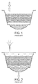
- Capsules of the prior art as illustrated in
figure 1 , feature a top membrane which is to be pierced by the fluid injection needle of the beverage preparation machine. When liquid is injected in the capsule compartment, a pressure is built up, which serves as an extraction means for extracting ingredients contained inside the capsule, as described above. - In prior art capsules, when the needle is removed from the capsule, after the beverage has been prepared and dispensed, the capsule top membrane is pierced and a hole remains as illustrated in
figure 2 . However, in such a case, the extraction fluid pressure "P" remains at least partly in the capsule compartment. - In case the capsule contains soluble ingredient to extract, the capsule compartment generally comprises one single portion, and the residual fluid pressure is distributed across the compartment volume.
- In case the capsule compartment is divided into several portions, as illustrated in
figures 1 and 2 , the residual pressure P is located in the top portion of the capsule compartment. In this case, the ingredient to be extracted, typically roast and ground coffee "RG", is contained in a central portion of the capsule, and a portion of the capsule compartment is disposed above said coffee ingredient, which is able to accommodate the fluid injection needle as illustrated infigure 1 . - In all cases, due to the residual pressure P which remains inside the capsule compartment after the capsule has been used, a jet of liquid - often referred to as "whale effect" - can spray out of the capsule top membrane, through the hole pierced by the machine needle. Such a whale effect is represented in
figure 2 . Although such a phenomenon occurs randomly and infrequently, it is undesirable because hot liquid splashing out is messy. Moreover, in case said liquid is water mixed with an ingredient such a leakage of liquid from the capsule top membrane is also undesirable for a cleanliness point of view as it could create some bacteria growth around or inside the machine, which forces the consumer to spend time cleaning the machine and its surroundings after usage. - It is therefore one main objective of the present invention to provide a capsule which prevents the so-called "whale effect" described above.
- The objective mentioned above is fulfilled with a capsule defining a closed chamber for enclosing a mass of soluble and/or extractable food material, for use in a beverage preparation machine, comprising:
- (i) capsule side walls,
- (ii) a top membrane pierceable by injection means of the machine which are adapted to inject an extraction liquid under pressure inside said chamber, and
- (iii) a bottom wall
- (iv) means adapted to open said chamber by relative engagement with the bottom wall under the effect of the liquid pressure increase in the chamber during injection of said liquid
characterized in that at least the portion of the top membrane surface which is to be pierced by the fluid injection means, comprises an elastic material having a tensile strength higher than 5 MPa, preferably higher than 10 MPa, and an elongation at break superior to 100%, preferably superior to 500%, such that said top membrane recloses in a leaktight manner, after said fluid injection means have been removed therefrom. - An elastic material suitable for the present invention should have a Young's modulus inferior to 150 GPa.
- Due to the elasticity of the material, the top membrane can be pierced easily and deform when the liquid injection means of the machine are moved through. Then, after the liquid has been injected into the capsule, the injection means is removed therefrom and the top membrane closes back in a leaktight manner due to its high elasticity.
- Preferably, the top membrane is able to withstand a fluid pressure of at least 1 bar, preferably at least 3 bar, more preferably at least 5 bar, after said fluid injection means have been removed therefrom.
- In a preferred embodiment of the present invention, the bottom wall is a pierceable membrane, made of aluminium, paper, plastic, or a combination thereof.
- Advantageously, the liquid injection means of the machine is a liquid injection hollow needle.
- In a first alternative of the invention, the top membrane comprises one single layer of elastic material (i.e. it is a so-called monolayer membrane).
- In a second alternative of the invention, the top membrane is a laminate comprising several superimposed layers which are at least partially assembled one to another, so that at least one of the constitutive layers of the laminate is made of an elastic material. Preferably, the lamination in the area where the needle pierces the top membrane is a weaker adhesion in comparison to other regions of the membrane, in order to facilitate the reclosing movement of the elastic layer.
- In a third alternative of the invention, the top membrane comprises a non elastic film, at least of portion of which is coated with a layer of an elastic material.
- In the third alternative, the elastic material is preferably coated onto said film in a liquid phase, which is then solidified by a heat or UV light treatment.
- In a fourth alternative of the invention, the top membrane comprises a non elastic film, at least of portion of which is covered with a layer of an elastic material with a glue using "sticker-like" application.
- In a fifth alternative of the invention, the top membrane of the capsule is coated at least on a portion of its surface with a layer of silicone that is applied over its melting temperature (i.e. as a liquid form) such that it then solidifies as it cools down onto the membrane onto which it is applied ("hot melt application").
- In all embodiments mentioned above, the elastic material is preferably a food-grade silicon, particularly a liquid mono-component silicon which is set by reaction with the atmospheric humidity (i.e. at ambient temperature). Examples of elastic materials include but are not limited to for instance: a food-grade thermoplastic elastomer such as SEBS (Styrene Ethylbutylene Styrene), silicone or liquid silicone rubber, or an ethylene vinyl alcohol (EVA) -based hot melt.
- Additional features and advantages of the present invention are described in, and will be apparent from, the description of the presently preferred embodiments which are set out below with reference to the drawings in which:
-
Figure 1 is schematic profile cut view of a capsule according to the prior art at the beginning of liquid injection therein; -
Figure 2 is a view similar tofigure 1 , showing the backflow of liquid under pressure after the injection needle has been removed from the top membrane; -
Figure 3 is a partial perspective exploded view illustrating the detail of a laminated top membrane according to the invention; -
Figure 4 is a schematic perspective view of a capsule according to the invention, wherein an elastic top ring is being deposited at the surface of the top membrane; -
Figure 5 is a schematic view similar tofigure 4 , showing an alternative embodiment of the invention; -
Figure 6 is a schematic profile cut view of a capsule according to the invention, showing the reclosed membrane after the injection needle is removed. - In the course of the present description, the term "top membrane" should be understood as the membrane which is pierced by the fluid injection needle of the machine, as opposed to the "bottom membrane" which should be understood as the membrane located on the opposite side of the capsule. This definition is such that "top" and "bottom" membranes are defined whatever the position of the capsule within the machine, when both capsule and machine are engaged in a functional manner.
- The
capsule 1 illustrated infigures 3, 4 ,5 and 6 comprises a capsule body defining a closed chamber for enclosing a mass of soluble and/or extractable food material "RG". - The capsule body comprises in particular:
- (i)
capsule side walls 2, - (ii) a top membrane 3 pierceable by an injection needle 4 of the machine which is adapted to inject an extraction liquid under pressure inside said chamber, and
- (iii) a bottom wall 5 being an aluminium membrane.
- As illustrated in
figure 6 , the capsule further comprises means adapted to open said chamber by relative engagement with the bottom wall under the effect of the liquid pressure increase in the chamber during injection of said liquid. These means comprise anrigid element 6 comprising spikes 7 on its surface turned towards the aluminium membrane 5. Therigid element 6 is generally referred to as "pyramid plate". Upon liquid injection inside the capsule compartment, pressure builds up, which deforms the aluminium membrane against the spikes 7 of thepyramid plate 6, until said membrane 5 is pierced, giving way to the beverage prepared inside the capsule towards the outside of the capsule, inside a cup (not illustrated). - According to the invention, at least the portion of the top membrane surface which is to be pierced by the fluid injection needle, comprises an elastic material having a tensile strength higher than 5 MPa, preferably higher than 10 MPa, and an elongation at break superior to 100%, preferably superior to 500%, such that said top membrane recloses in a leaktight manner, after said fluid injection means have been removed therefrom. More precisely, the top membrane is able to withstand a fluid pressure of at least 3 bar after said fluid injection means have been removed therefrom.
- In a first embodiment illustrated in
figure 3 , the top membrane 3 is a laminate comprising severalsuperimposed layers 8 which are at least partially assembled one to another, so that at least one of the constitutive layers of the laminate is made of an elastic material. For instance, in the embodiment illustrated infigure 3 , the top membrane 3 comprises four superimposed layers. Thelowermost layer 9 comprises an elastic silicone layer having a tensile strength of about 10 MPa, and an elongation at break of about 700%. The firstintermediate layer 10 disposed immediately above is made of a polypropylene material (Young's modulus of about 1.5 GPa and yield strength of about 40 MPa). The secondintermediate layer 11 disposed immediately above is made of an elastic silicone layer having a tensile strength of about 10 MPa, and an elongation at break of about 700%. And theuppermost layer 12 is made of a polyethylene (Young's modulus of about 0.6 GPa and yield strength of about 35 MPa). - In a second embodiment illustrated in
figure 4 , the top membrane 3 is coated with aring 13 of silicone deposited as a liquid onto the capsule top membrane surface. More precisely, a portion of the top membrane upper surface is coated with a layer of a silicone elastic material having a tensile strength of about 10 MPa, and an elongation at break of about 700%. The layer of silicone is deposited as a liquid and then set at room temperature by using UV light treatment. The silicone that is used is food grade. Thering 13 has a thickness of between 0.1 and 1 mm, preferably a thickness between 0.3 mm and 0.7 mm. It has width larger than the diameter of the liquid injection needle 4, preferably three times as large as the needle. The ring is positioned onto the top membrane 3 in such a way that whatever the rotational position of the capsule in the machine, the needle pierces through the zone of said top membrane which is coated with the silicone ring. It could also be envisaged that the lower surface of the top membrane be coated with an elastic material, however such an embodiment is not preferred as it is considered easier to coat the upper side of said top membrane. - In a third embodiment illustrated in
figure 5 , the top membrane 3 is bonded with a ring ofsilicone 13. The material used for the ring is a silicone elastic material having a tensile strength of about 10 MPa, and an elongation at break of about 700%. Thering 13 has a thickness of between 0.1 and 1 mm, preferably a thickness between 0.3 mm and 0.7 mm. It has width larger than the diameter of the liquid injection needle 4, preferably twice as large as the needle. The ring is positioned onto the top membrane 3 in such a way that whatever the rotational position of the capsule in the machine, the needle pierces through the zone of said top membrane which is coated with the silicone ring, as illustrated infigure 5 . Thering 13 is bonded to the top membrane 4 using a food-grade adhesive. - Instead of a ring shape, which is preferable as the consumer does not need to orient the capsule, it is possible to have only a simple disc which is deposited as a disc of liquid silicone which is then set as described above, or alternatively, as a premade disc of silicone which is attached to the surface of the membrane by glue. Such a disc of silicone (not illustrated in the drawing) has a diameter of at least twice the diameter of the needle. In that case, the capsule shape is preferably modified in a non circular shape, in order to provide an orientation of the capsule inside the capsule holder or inside the machine, in such a way that, in operation, the needle pierces through the disc. Alternatively, the capsule design or a drawing on the capsule indicates the consumer what is the correct orientation of the capsule inside the capsule holder or inside the machine.
- In all embodiments described above, laboratory tests showed that layers of an elastomer such as silicone ― alone or in combination as a layer in a multilayer membrane, or a s coating or ring -, wherein the elastomer layer as a thickness of between 0.1 and 1 mm, preferably a thickness between 0.3 mm and 0.7 mm delivers good results in terms of reclosability and leak tightness, when the internal residual pressure inside the capsule after product preparation is between 0.5 and 5 bar (relative pressure to atmospheric pressure).
- In such tests, the diameter of the needle was comprised between 0.5 mm and 3 mm, and more precisely between 1.0 mm and 1.6 mm. For instance the needle can have 1.5 mm in diameter with a 30° apex cut angle. The needle used for the liquid injection in the capsule is stainless steel.
- It should be understood that various changes and modifications to the presently preferred embodiments described herein will be apparent to those skilled in the art. Such changes and modifications can be made without departing from the spirit and scope of the present invention and without diminishing its attendant advantages. It is therefore intended that such changes and modifications be covered by the appended claims.
Claims (9)
- A capsule (1) defining a closed chamber for enclosing a mass of soluble and/or extractable food material, for use in a beverage preparation machine, comprising:(i) capsule side walls (2),(ii) a top membrane (3) pierceable by injection means (4) of the machine which are adapted to inject an extraction liquid under pressure inside said chamber, and(iii) a bottom wall (5)(iv) means (6, 7) adapted to open said chamber by relative engagement with the bottom wall (5) under the effect of the liquid pressure increase in the chamber during injection of said liquid characterized in that at least the portion of the top membrane surface which is to be pierced by the fluid injection means (4), comprises an elastic material having a tensile strength higher than 5 MPa, preferably higher than 10 MPa, and an elongation at break superior to 100%, preferably superior to 500%, such that said top membrane (3) recloses in a leaktight manner, after said fluid injection means (4) have been removed therefrom.
- A capsule (1) according to claim 1, wherein said top membrane (3) is able to withstand, without leaking, a fluid pressure of at least 1 bar, preferably at least 3 bar, more preferably at least 5 bar, after said fluid injection means (4) have been removed therefrom.
- A capsule (1) according to any of the preceding claims, wherein said bottom wall is a pierceable membrane (5), made of aluminium, paper, plastic, or a combination thereof.
- A capsule (1) according to any of the preceding claims, wherein the top membrane (3) is pierceable by a liquid injection hollow needle (4) of the machine.
- A capsule (1) according to any of the preceding claims 1 to 4, wherein the top membrane (3) comprises one single layer of elastic material.
- A capsule (1) according to any of the preceding claims 1 to 4, wherein the top membrane (3) is a laminate comprising several superimposed layers (8) which are at least partially assembled one to another, so that at least one of the constitutive layers (9, 11) of the laminate is made of an elastic material.
- A capsule (1) according to any of the preceding claims, wherein the top membrane (3) comprises a non elastic film, at least of portion of which is coated with a layer of an elastic material.
- A capsule (1) according to claim 7, wherein the elastic material is coated onto said film in a liquid phase, which is either a polymer applied as a hot melt, over its melting temperature which then solidifies as it cools down, or in cold liquid elastomer form that is then set to solidify by a heat or UV light treatment.
- A capsule (1) according to any of the preceding claims, wherein said elastic material is a food-grade silicone.
Priority Applications (8)
| Application Number | Priority Date | Filing Date | Title |
|---|---|---|---|
| EP11178246A EP2562101A1 (en) | 2011-08-22 | 2011-08-22 | A capsule for use in a beverage preparation machine |
| ES12740165.1T ES2564023T3 (en) | 2011-08-22 | 2012-07-27 | A capsule to use in a beverage preparation machine |
| PCT/EP2012/064752 WO2013026650A1 (en) | 2011-08-22 | 2012-07-27 | A capsule for use in a beverage preparation machine |
| JP2014526434A JP6014673B2 (en) | 2011-08-22 | 2012-07-27 | Capsules for use in beverage preparation machines |
| US14/240,136 US9371175B2 (en) | 2011-08-22 | 2012-07-27 | Capsule for use in a beverage preparation machine |
| CN201280041106.5A CN103748022B (en) | 2011-08-22 | 2012-07-27 | Capsules for use in beverage preparation machines |
| EP12740165.1A EP2748086B1 (en) | 2011-08-22 | 2012-07-27 | A capsule for use in a beverage preparation machine |
| ARP120103068A AR087613A1 (en) | 2011-08-22 | 2012-08-21 | A CAPSULE FOR USE IN A MACHINE TO PREPARE DRINKS |
Applications Claiming Priority (1)
| Application Number | Priority Date | Filing Date | Title |
|---|---|---|---|
| EP11178246A EP2562101A1 (en) | 2011-08-22 | 2011-08-22 | A capsule for use in a beverage preparation machine |
Publications (1)
| Publication Number | Publication Date |
|---|---|
| EP2562101A1 true EP2562101A1 (en) | 2013-02-27 |
Family
ID=46581989
Family Applications (2)
| Application Number | Title | Priority Date | Filing Date |
|---|---|---|---|
| EP11178246A Withdrawn EP2562101A1 (en) | 2011-08-22 | 2011-08-22 | A capsule for use in a beverage preparation machine |
| EP12740165.1A Not-in-force EP2748086B1 (en) | 2011-08-22 | 2012-07-27 | A capsule for use in a beverage preparation machine |
Family Applications After (1)
| Application Number | Title | Priority Date | Filing Date |
|---|---|---|---|
| EP12740165.1A Not-in-force EP2748086B1 (en) | 2011-08-22 | 2012-07-27 | A capsule for use in a beverage preparation machine |
Country Status (7)
| Country | Link |
|---|---|
| US (1) | US9371175B2 (en) |
| EP (2) | EP2562101A1 (en) |
| JP (1) | JP6014673B2 (en) |
| CN (1) | CN103748022B (en) |
| AR (1) | AR087613A1 (en) |
| ES (1) | ES2564023T3 (en) |
| WO (1) | WO2013026650A1 (en) |
Cited By (5)
| Publication number | Priority date | Publication date | Assignee | Title |
|---|---|---|---|---|
| WO2014198586A1 (en) * | 2013-06-11 | 2014-12-18 | Nestec S.A. | A capsule for food or beverage preparation |
| CN105555680A (en) * | 2013-07-05 | 2016-05-04 | 诺威德尔塔咖啡贸易工业有限公司 | Capsule, beverage preparation system comprising said capsule, and method for operating said system |
| US10273076B2 (en) | 2013-05-17 | 2019-04-30 | Koninklijke Douwe Egberts B.V. | Beverage preparation system, a capsule and a method for forming a beverage |
| US10730691B2 (en) | 2013-05-17 | 2020-08-04 | Koninklijke Douwe Egberts B.V. | Beverage preparation system, a capsule and a method for forming a beverage |
| US10960453B2 (en) | 2014-11-14 | 2021-03-30 | Koninklijke Douwe Egberts B.V. | Method of forming a cup-shaped body for a beverage capsule |
Families Citing this family (19)
| Publication number | Priority date | Publication date | Assignee | Title |
|---|---|---|---|---|
| US11832755B2 (en) * | 2007-07-13 | 2023-12-05 | Adrian Rivera | Brewing material container for a beverage brewer |
| US10722066B2 (en) * | 2010-12-04 | 2020-07-28 | Adrian Rivera | Windowed single serving brewing material holder |
| US10071851B2 (en) | 2010-07-12 | 2018-09-11 | Robert Bao Vu | Apparatus and products for producing beverages, and methods for making and using same |
| LT3023362T (en) * | 2010-07-22 | 2018-04-25 | K-Fee System Gmbh | Portion capsule having an identifier |
| JP2018513064A (en) * | 2015-03-23 | 2018-05-24 | アルトリア クライアント サービシーズ エルエルシー | Disposable package for beverage production equipment |
| USD797502S1 (en) * | 2015-05-25 | 2017-09-19 | Bisio Progetti S.P.A. | Beverage capsule |
| USD796898S1 (en) | 2015-07-13 | 2017-09-12 | Bisio Progetti S.P.A. | Beverage capsule |
| GB201521882D0 (en) | 2015-12-11 | 2016-01-27 | Mars Inc | Beverage preperation system and capsules |
| EP3423381B1 (en) | 2016-03-01 | 2022-04-27 | Bartesian Inc. | Beverage machine and capsule for use with the beverage machine |
| US11524268B2 (en) | 2016-11-09 | 2022-12-13 | Pepsico, Inc. | Carbonated beverage makers, methods, and systems |
| USD890569S1 (en) | 2018-06-19 | 2020-07-21 | Bartesian Inc. | Beverage capsule receiving adaptor |
| JP1643001S (en) * | 2018-06-28 | 2019-10-07 | ||
| JP1643129S (en) * | 2018-06-28 | 2019-10-07 | ||
| US20220009704A1 (en) * | 2018-11-20 | 2022-01-13 | Societe Des Produits Nestle S.A. | Capsule for food or beverage preparation comprising an oversized membrane |
| CH716555A1 (en) * | 2019-09-04 | 2021-03-15 | Daetwyler Schweiz Ag | Process for the production of a beverage capsule with a sealing ring. |
| AU2021336070A1 (en) * | 2020-09-02 | 2023-03-09 | Société des Produits Nestlé S.A. | Biodegradable capsule with integrated opening means |
| US20230382632A1 (en) * | 2020-10-05 | 2023-11-30 | Societe Des Produits Nestle S.A. | Biodegradable top membrane for a beverage capsule |
| CN116323429A (en) * | 2020-10-21 | 2023-06-23 | 雀巢产品有限公司 | Containers enclosing doses of food or drink ingredients, assemblies comprising such containers and food or drink preparation machines, and food or drink preparation processes for obtaining such assemblies |
| US11805934B1 (en) * | 2020-10-21 | 2023-11-07 | Adrian Rivera | Brewing material lid and container for a beverage brewer |
Citations (8)
| Publication number | Priority date | Publication date | Assignee | Title |
|---|---|---|---|---|
| CH605293A5 (en) | 1976-12-17 | 1978-09-29 | Nestle Sa | |
| EP0242556A1 (en) | 1986-04-24 | 1987-10-28 | Societe Des Produits Nestle S.A. | Beverage-extracting device for cartridges |
| EP1472156B1 (en) | 2002-01-16 | 2006-03-29 | Societe Des Produits Nestle S.A. | Closed capsule with opening mean |
| DE202006013189U1 (en) * | 2006-08-25 | 2006-10-26 | Tchibo Gmbh | Hot beverage e.g. meal coffee, making system, has jacket base with silicon plate having hole which is sealed depending on material properties of plate, before lower mandrel is pulled out from plate |
| EP1864917A1 (en) * | 2006-06-06 | 2007-12-12 | Nestec S.A. | Capsule with reduced dripping |
| WO2008116818A1 (en) * | 2007-03-23 | 2008-10-02 | Nestec S.A. | Beverage ingredient capsule with opening plate having pressure-relief openings |
| EP1784344B1 (en) | 2004-08-23 | 2009-04-08 | Nestec S.A. | Capsule for preparing and delivering a drink by injecting a pressurized fluid into the capsule |
| EP2162653A1 (en) | 2007-05-16 | 2010-03-17 | Nestec S.A. | Control device having a peristaltic valve for a drink preparing machine |
Family Cites Families (6)
| Publication number | Priority date | Publication date | Assignee | Title |
|---|---|---|---|---|
| US20050051478A1 (en) * | 2003-09-10 | 2005-03-10 | Basil Karanikos | Beverage filter cartridge |
| DE202004021229U1 (en) * | 2004-11-19 | 2007-03-29 | Tchibo Gmbh | Coffee machine for brewing coffee comprises a control unit for preparing different pressures for compressed water |
| ES2661027T3 (en) * | 2007-01-15 | 2018-03-27 | Swiss Caffe Asia Ltd. | Capsule, means of penetration of the bottom of a capsule and device for preparing a beverage |
| US20100078480A1 (en) * | 2008-09-29 | 2010-04-01 | Symbol Technologies, Inc. | Method of positioning the barcode |
| CA2745239A1 (en) * | 2008-12-03 | 2010-06-10 | Nestec S.A. | Capsule for the preparation of a beverage by centrifugation |
| US8474368B2 (en) * | 2009-05-13 | 2013-07-02 | Curwood, Inc. | Mineral composite beverage brewing cup and cartridge |
-
2011
- 2011-08-22 EP EP11178246A patent/EP2562101A1/en not_active Withdrawn
-
2012
- 2012-07-27 ES ES12740165.1T patent/ES2564023T3/en active Active
- 2012-07-27 JP JP2014526434A patent/JP6014673B2/en not_active Expired - Fee Related
- 2012-07-27 EP EP12740165.1A patent/EP2748086B1/en not_active Not-in-force
- 2012-07-27 WO PCT/EP2012/064752 patent/WO2013026650A1/en not_active Ceased
- 2012-07-27 US US14/240,136 patent/US9371175B2/en not_active Expired - Fee Related
- 2012-07-27 CN CN201280041106.5A patent/CN103748022B/en not_active Expired - Fee Related
- 2012-08-21 AR ARP120103068A patent/AR087613A1/en not_active Application Discontinuation
Patent Citations (9)
| Publication number | Priority date | Publication date | Assignee | Title |
|---|---|---|---|---|
| CH605293A5 (en) | 1976-12-17 | 1978-09-29 | Nestle Sa | |
| EP0242556A1 (en) | 1986-04-24 | 1987-10-28 | Societe Des Produits Nestle S.A. | Beverage-extracting device for cartridges |
| EP1472156B1 (en) | 2002-01-16 | 2006-03-29 | Societe Des Produits Nestle S.A. | Closed capsule with opening mean |
| EP1784344B1 (en) | 2004-08-23 | 2009-04-08 | Nestec S.A. | Capsule for preparing and delivering a drink by injecting a pressurized fluid into the capsule |
| EP2062831A2 (en) | 2004-08-23 | 2009-05-27 | Nestec S.A. | Capsule for preparing and delivering a drink by injecting a pressurized fluid into the capsule |
| EP1864917A1 (en) * | 2006-06-06 | 2007-12-12 | Nestec S.A. | Capsule with reduced dripping |
| DE202006013189U1 (en) * | 2006-08-25 | 2006-10-26 | Tchibo Gmbh | Hot beverage e.g. meal coffee, making system, has jacket base with silicon plate having hole which is sealed depending on material properties of plate, before lower mandrel is pulled out from plate |
| WO2008116818A1 (en) * | 2007-03-23 | 2008-10-02 | Nestec S.A. | Beverage ingredient capsule with opening plate having pressure-relief openings |
| EP2162653A1 (en) | 2007-05-16 | 2010-03-17 | Nestec S.A. | Control device having a peristaltic valve for a drink preparing machine |
Cited By (9)
| Publication number | Priority date | Publication date | Assignee | Title |
|---|---|---|---|---|
| US10273076B2 (en) | 2013-05-17 | 2019-04-30 | Koninklijke Douwe Egberts B.V. | Beverage preparation system, a capsule and a method for forming a beverage |
| US10730691B2 (en) | 2013-05-17 | 2020-08-04 | Koninklijke Douwe Egberts B.V. | Beverage preparation system, a capsule and a method for forming a beverage |
| US12312155B2 (en) | 2013-05-17 | 2025-05-27 | Koninklijke Douwe Egberts B.V. | Beverage preparation system, a capsule and a method for forming a beverage |
| WO2014198586A1 (en) * | 2013-06-11 | 2014-12-18 | Nestec S.A. | A capsule for food or beverage preparation |
| CN105307953A (en) * | 2013-06-11 | 2016-02-03 | 雀巢产品技术援助有限公司 | A capsule for food or beverage preparation |
| CN105307953B (en) * | 2013-06-11 | 2017-06-30 | 雀巢产品技术援助有限公司 | For capsule prepared by food |
| US10099848B2 (en) | 2013-06-11 | 2018-10-16 | Nestec S.A. | Capsule for food or beverage preparation |
| CN105555680A (en) * | 2013-07-05 | 2016-05-04 | 诺威德尔塔咖啡贸易工业有限公司 | Capsule, beverage preparation system comprising said capsule, and method for operating said system |
| US10960453B2 (en) | 2014-11-14 | 2021-03-30 | Koninklijke Douwe Egberts B.V. | Method of forming a cup-shaped body for a beverage capsule |
Also Published As
| Publication number | Publication date |
|---|---|
| JP6014673B2 (en) | 2016-10-25 |
| ES2564023T3 (en) | 2016-03-17 |
| EP2748086A1 (en) | 2014-07-02 |
| US20140186498A1 (en) | 2014-07-03 |
| WO2013026650A1 (en) | 2013-02-28 |
| US9371175B2 (en) | 2016-06-21 |
| AR087613A1 (en) | 2014-04-03 |
| CN103748022B (en) | 2016-12-21 |
| CN103748022A (en) | 2014-04-23 |
| JP2014524317A (en) | 2014-09-22 |
| EP2748086B1 (en) | 2016-02-03 |
Similar Documents
| Publication | Publication Date | Title |
|---|---|---|
| EP2748086B1 (en) | A capsule for use in a beverage preparation machine | |
| EP2892824B1 (en) | A beverage capsule with anti-dripping membrane | |
| EP2847101B1 (en) | An ingredient capsule for beverage preparation | |
| US10822160B2 (en) | Capsule for beverage preparation | |
| EP2847100B1 (en) | An ingredient capsule for beverage preparation | |
| AU2014273107B2 (en) | A capsule for beverage preparation | |
| EP2847099B1 (en) | An ingredient capsule for beverage preparation | |
| EP2888183B1 (en) | A capsule for use with a food preparation machine | |
| CN104718142A (en) | Beverage capsule with an opening system | |
| HK1181368A (en) | A capsule for use in a beverage preparation machine |
Legal Events
| Date | Code | Title | Description |
|---|---|---|---|
| PUAI | Public reference made under article 153(3) epc to a published international application that has entered the european phase |
Free format text: ORIGINAL CODE: 0009012 |
|
| AK | Designated contracting states |
Kind code of ref document: A1 Designated state(s): AL AT BE BG CH CY CZ DE DK EE ES FI FR GB GR HR HU IE IS IT LI LT LU LV MC MK MT NL NO PL PT RO RS SE SI SK SM TR |
|
| AX | Request for extension of the european patent |
Extension state: BA ME |
|
| STAA | Information on the status of an ep patent application or granted ep patent |
Free format text: STATUS: THE APPLICATION HAS BEEN WITHDRAWN |
|
| 18W | Application withdrawn |
Effective date: 20130819 |
|
| REG | Reference to a national code |
Ref country code: HK Ref legal event code: DE Ref document number: 1181368 Country of ref document: HK |
|
| REG | Reference to a national code |
Ref country code: HK Ref legal event code: WD Ref document number: 1181368 Country of ref document: HK |