EP2561794A1 - Endoscope operating section, and endoscope - Google Patents
Endoscope operating section, and endoscope Download PDFInfo
- Publication number
- EP2561794A1 EP2561794A1 EP11771880A EP11771880A EP2561794A1 EP 2561794 A1 EP2561794 A1 EP 2561794A1 EP 11771880 A EP11771880 A EP 11771880A EP 11771880 A EP11771880 A EP 11771880A EP 2561794 A1 EP2561794 A1 EP 2561794A1
- Authority
- EP
- European Patent Office
- Prior art keywords
- switch button
- endoscope
- operation section
- switch
- button
- Prior art date
- Legal status (The legal status is an assumption and is not a legal conclusion. Google has not performed a legal analysis and makes no representation as to the accuracy of the status listed.)
- Granted
Links
Images




Classifications
-
- A—HUMAN NECESSITIES
- A61—MEDICAL OR VETERINARY SCIENCE; HYGIENE
- A61B—DIAGNOSIS; SURGERY; IDENTIFICATION
- A61B1/00—Instruments for performing medical examinations of the interior of cavities or tubes of the body by visual or photographical inspection, e.g. endoscopes; Illuminating arrangements therefor
- A61B1/005—Flexible endoscopes
- A61B1/0051—Flexible endoscopes with controlled bending of insertion part
- A61B1/0052—Constructional details of control elements, e.g. handles
-
- A—HUMAN NECESSITIES
- A61—MEDICAL OR VETERINARY SCIENCE; HYGIENE
- A61B—DIAGNOSIS; SURGERY; IDENTIFICATION
- A61B1/00—Instruments for performing medical examinations of the interior of cavities or tubes of the body by visual or photographical inspection, e.g. endoscopes; Illuminating arrangements therefor
- A61B1/00064—Constructional details of the endoscope body
- A61B1/00066—Proximal part of endoscope body, e.g. handles
- A61B1/00068—Valve switch arrangements
-
- G—PHYSICS
- G02—OPTICS
- G02B—OPTICAL ELEMENTS, SYSTEMS OR APPARATUS
- G02B23/00—Telescopes, e.g. binoculars; Periscopes; Instruments for viewing the inside of hollow bodies; Viewfinders; Optical aiming or sighting devices
- G02B23/24—Instruments or systems for viewing the inside of hollow bodies, e.g. fibrescopes
- G02B23/2476—Non-optical details, e.g. housings, mountings, supports
Definitions
- the present invention relates to an endoscope operation section provided at a proximal end of an insertion portion of an endoscope, and an endoscope.
- endoscopes have widely been used in a medical field and an industrial field.
- an elongated insertion portion is inserted into a body cavity, which is a subject, whereby an organ in the body cavity can be observed and as necessary various types of treatments can be performed using a treatment instrument inserted in a treatment instrument insertion channel included in the endoscope.
- an elongated insertion portion of an endoscope is inserted into an object such as a jet engine or a piping in a plant, whereby observation of, e.g., flaws and corrosion of a site to be inspected in the object or inspection of, e.g., various types of treatments can be performed.
- an operation section that is grasped by an operator and includes, e.g., button switches, levers and knobs for performing various types of operation of the endoscope is provided.
- a grasping region which is grasped by an operator, is formed on the insertion portion side, and various types of operation members such as bending operation knobs or bending operation levers for performing bending operation of a bending portion provided in the insertion portion, a power supply switch button for the endoscope, a release switch button for providing an instruction to record an image picked up by an image pickup unit, a freeze switch button for providing an instruction to freeze the picked-up image, a zoom switch button for the image pickup unit, switch buttons for air/water sending operation and switch button for suction operation are provided in a region of the operation portion away from the insertion portion relative to the grasping region.
- various types of operation members such as bending operation knobs or bending operation levers for performing bending operation of a bending portion provided in the insertion portion, a power supply switch button for the endoscope, a release switch button for providing an instruction to record an image picked up by an image pickup unit, a freeze switch button for providing an instruction to freeze the picked-up image, a zoom switch button for the
- an operator grasps the insertion portion with his right hand in order to send the insertion portion into a subject, and thus, in general, the operation section is grasped by the left hand and the aforementioned various types of operation members provided at the operation section are operated using the respective fingers of the left hand.
- switch buttons are arranged side by side at the operation section
- the operator who is operating the endoscope while viewing an endoscopic image picked up by the image pickup unit operates the buttons without viewing the operation section, causing the problem of, for example, a switch button that is different from a switch button for desired operation being pushed by a finger of the left hand, that is, a switch being mistakenly operated.
- Japanese Patent Application Laid-Open Publication No. 2002-58629 Japanese Utility Model Application Laid-Open Publication No. 57-84901 and Japanese Patent Application Laid-Open Publication No. 56-72837 each disclose a configuration in which a wall portion is provided between adjacent switch buttons to make an operator recognize the positions of the buttons by mean of the wall portion, preventing erroneous pushing of the buttons.
- Some of the aforementioned various types of switch buttons may be provided in a known switch box, which is provided at an end portion of the operation section on the side opposite to the insertion portion in the direction in which the insertion portion is inserted. Also, for operability enhancement, there is a demand for arranging two switch buttons on a same surface of a switch box.
- the outer diameters of the respective switch buttons may be reduced; however, in this case, there is the problem of a decrease in operability of the switch buttons relative to conventional ones, especially for operators having fat fingers.
- an operation section is grasped by a left hand in such a manner that a base of a known universal cord extending from a left side of the operation section is held between the thumb and the index finger of the left hand and the chassis of the operation section is grasped by the remaining middle finger, ring finger and little finger, bending operation knobs provided on a right side of the operation section and two switch buttons provided on a front surface of a switch box are operated by the thumb and switch buttons provided on an upper surface and a back surface of the switch box are operated by the index finger and the middle finger.
- the present invention has been made in views of the aforementioned circumstances and problems, and an object of the present invention is to provide an endoscope operation section and an endoscope, which include a configuration in which two switch buttons can be arranged side by side in a space-saving manner and misoperation of the switch buttons can be prevented without decreasing the operability of the switch buttons.
- An endoscope operation section includes: an angle operation member for bending a bending portion provided in an insertion portion of an endoscope, the angle operation member being provided in an operation section body of the endoscope operation section provided at a proximal end of the insertion portion; a first switch button for performing first operation of the endoscope, the first switch button being provided in a first surface of the operation section body; and a second switch button for performing second operation of the endoscope, the second switch button being provided side by side with the first switch button in the first surface and positioned on a side distant from the angle operation member relative to the first switch button.
- An outer circumferential side of the second switch button is covered by a sheathing member of the operation section body, and a projection portion is formed at a site of the sheathing member, the site facing the first switch button, on an outer circumference of the second switch button, the projection portion projecting toward a side away from the first surface relative to another site of the sheathing member on the outer circumference of the second switch button.
- an endoscope according to another aspect includes the endoscope operation section according to any one of claims 1 to 7.
- drawings are schematic ones and, e.g., the relationship between a thickness and a width of each member and the ratios in thickness between the respective members are different from actual ones, and it should be understood that the drawings include parts that are different in dimensional relationship and/or ratio from one another.
- Fig. 1 is a partial perspective view of an endoscope including an endoscope operation section according to the present embodiment
- Fig. 2 is a partial perspective view of the endoscope in Fig. 1 taken in the direction of arrow II in Fig. 1
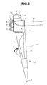
- Fig. 3 is a partial perspective view of the endoscope in Figs. 1 and 2 taken in the direction of arrow III in Figs. 1 and 2
- Fig. 4 is a partial perspective view of the endoscope in Fig. 1 taken in the direction of arrow IV in Fig. 1
- Fig. 5 is a partial perspective view of the endoscope in Fig. 1 taken in the direction of arrow V in Fig. 1 .
- Fig. 6 is a partial perspective view of an enlargement of an area in the vicinity of a first switch button and a second switch button in the endoscope operation section in Fig. 1 ;
- Fig. 7 is a partial perspective view of a state in which the endoscope operation section in Fig. 1 is grasped by the left hand of an operator;
- Fig. 8 is a partial cross-sectional view of the endoscope operation section taken along line VIII-VIII in Fig. 6 , centering on the second switch button.
- a main portion of an endoscope 100 includes an insertion portion 2 to be inserted into a subject, an endoscope operation section (hereinafter simply referred to as the operation section) 1 provided on the proximal end side of the insertion portion 2, a universal cord 3 extending from a third surface 1t (see Figs. 3 and 4 ) adjacent to a first surface 1f of the operation section 1, which will be described later, and a non-illustrated connector provided at an extension end of the universal cord 3.
- the operation section hereinafter simply referred to as the operation section
- a grasping region 1r which is grasped by the palm, the ring finger LM and the little finger LK of the left hand L of an operator, is formed on the insertion portion 2 side, and various types of operation switches are provided in a region of the operation section body 1h on the side away from the insertion portion 2 relative to the grasping region 1r (hereinafter referred to as the upper side).
- a switch box 4 is provided at an end portion of the operation section body 1h that is away from the insertion portion 2 (hereinafter referred to as the upper portion).
- a first switch button 21 for performing first operation of the endoscope 100 and a second switch button 22 for performing second operation of the endoscope 100 are provided on a first surface 4f of the switch box 4, which is included in the first surface 1f of the operation section body 1h.
- the first switch button 21 may be a frequently-used switch button, for example, a release switch button for providing an instruction to record an image picked up by a non-illustrated image pickup unit provided in a distal end of the insertion portion 2.
- the second switch button 22 may be a less frequently-used switch button, for example, a zoom switch button for the aforementioned image pickup unit.
- the first operation is operation for an image recording instruction and the second instruction is zoom operation.
- configurations and arrangement of the first switch button 21 and the second switch button 22 will be described later.
- a power switch button 23 for turning on/off a power supply of the endoscope 100 is provided on an upper surface 4j of the switch box 4 included in an upper surface 1j of the operation section body 1h.
- an iris switch button 24 for changing an exposure measuring method is provided on a back surface 4b of the switch box 4 included in a back surface 1b of the operation section body 1h.
- the power supply switch button 23 and the iris switch button 24 may be provided offset from a center e of the switch box in a direction away from bending operation knobs 11 and 12, which will be described later, in a direction Q in which the first switch button 21 and the second switch button 22 are arranged side by side, in the upper surface 4j and the back surface 4b of the switch box 4, respectively.
- a reason for this is: as illustrated in Fig. 7 , when the operation section body 1h is grasped by a left hand L in such a manner that a base of the universal cord 3 extending from the third surface 1t of the operation section body 1h is held between the thumb LO and the index finger LH of the left hand L, the power supply switch button 23 and the iris switch button 24 are operated by the index finger LH. Accordingly, in this way of grasping, if the power supply switch button 23 and the iris switch button 24 are provided offset in the direction away from the bending operation knobs 11 and 12 in the direction Q, distances from the respective switches 23 and 24 to the index finger LH become short, facilitating operation by the index finger LH.
- the bending operation knobs 11 and 12 which are angle operation members for bending a non-illustrated bending portion provided in the insertion portion 2, are provided at a site of a second surface 1s that is adjacent to the first surface 1f and faces the third surface 1t, the site being on the upper side relative to the grasping region 1r of the operation section body 1h and on the insertion portion 2 side (hereinafter referred to as the lower side) relative to the switch box 4.
- the angle operation members are not limited to knobs and may be other operation members such as levers and/or switch buttons. Also, where the first surface 4f of the switch box 4 is very large, the angle operation members may be provided in the first surface 4f.
- the bending operation knob 11 is a knob that is operated to rotate in order to vertically bend the aforementioned bending portion, and a rotational position thereof is fixed by means of operation of a rotational position fixing lever 14.
- the bending operation knob 12 is a knob that is operated to rotate in order to horizontally bend the aforementioned bending portion, and a rotational position thereof is fixed by means of operation of a rotational position fixing dial 13.
- a freeze switch button 28 for providing an instruction to freeze an image picked up by the image pickup unit a known switch button 26 for air/water sending operation and a switch button 27 for suction operation are provided at a site of the back surface 1b of the operation section body 1h, the site being on the upper side relative to the grasping region 1r and on the lower side relative to the switch box 4.
- the freeze switch button 28, the switch button 26 for air/water sending operation and the switch button 27 for suction operation are operated by the index finger LH and the middle finger LN.
- the first switch button 21 and the second switch button 22 are arranged side by side along a direction Q in the first surface 4f of the switch box 4, the second switch button 22 is positioned on the side distant from the bending operation knobs 11 and 12 in the direction Q relative to the first switch button 21.
- first switch button 21 and the second switch button 22 are arranged at positions in the first surface 4f where the first switch button 21 and the second switch button 22 are operated by the thumb LO when the operation section body 1h is grasped by the left hand L in such a manner that the base of the universal cord 3 is held between the thumb LO and the index finger LH of the left hand L as illustrated in Fig. 7 .
- first switch button 21 and the second switch button 22 are arranged in the first surface 4f so as to be positioned on an outer circumference R of a circle with the base P of the thumb LO as a center as illustrated in Fig. 4 when the operation section body 1h is grasped by the left hand L in such a manner that the base of the universal cord 3 is held by the thumb LO and the index finger LH of the left hand L as illustrated in Fig. 7 .
- the second switch button 22 is arranged in the first surface 4f so as to be positioned on a line f extending from a point G where the thumb LO abuts to the universal cord 3 in a direction in which the operation section body 1h extends when the operation section body 1h is grasped by the left hand L in such a manner that the base of the universal cord 3 is grasped between the thumb LO and the index finger LH of the left hand L as illustrated in Fig. 7 .
- the second switch button 22 may be arranged on the side away from the bending operation knobs 11 and 12 in the direction Q relative to the line f.
- a part on an outer circumferential side of the first switch button 21 is covered by a sheathing member providing the first surface 4f of the switch box 4, and a pushing surface 21p is exposed.
- a part on an outer circumferential side of the second switch button 22 is covered by the sheathing member providing the first surface 4f of the switch box 4. More specifically, the part on the outer circumferential side of the second switch button 22 is covered by the second switch button 22 being fitted in a fitting portion 7 formed in the sheathing member, and the pushing surface 22p is exposed.
- the part on the outer circumferential side of the second switch button 22 may be covered by the sheathing member providing in the first surface 4f of the switch box 4 alone.
- a projection portion 7t is formed at a site of the fitting portion 7, the site facing the first switch button 21 in the one direction Q, on the outer circumference of the second switch button 22, the projection portion 7t projecting toward the side away from the first surface 4f relative to another site 7a of the fitting portion 7.
- the projection portion 7t is a member that prevents the first switch button 21 or the second switch button 22 from being pushed in error for the second switch button 22 or the first switch button 21 by the thumb LO and makes the operator who cannot see the operation section body 1h during operation recognize a position of the thumb LO when the operation section body 1h is held by the left hand L in such a manner that the base of the universal cord 3 is held between the thumb LO and the index finger LH of the left hand L as illustrated in Fig. 7 .
- the projection portion 7t is provided only at the site of the fitting portion 7 that faces the first switch button 21 in the direction Q, not on the entire outer circumference of the second switch button 22 because if the projection portion 7t is provided on the entire circumference, the projection portion 7t provided on the entire circumference becomes an obstacle for operators with a large thumb LO, making it difficult to perform pushing operation of the second switch button 22.
- a height of a projection of the projection portion 7t is set as indicated in Fig. 8 . More specifically, where a gap between an upper surface 7tc of the projection portion 7t and an apex of the pushing surface 22p of the second switch button 22 is set as ⁇ and a gap between a switch surface 30a of an electronic switch 30 provided in the second switch button 22 and a switch-on/off surface 22k of the second switch button 22 is set as ⁇ , it is only necessary that ⁇ ⁇ ⁇ . In other words, it is only necessary that the upper surface 7tc be higher than a value resulting from ⁇ being subtracted from the apex of the pushing surface 22p.
- the first switch button 21 Although there is no projection portion on an outer circumference of the first switch button 21, where a gap between an apex of the pushing surface 21p of the first switch button 21 and the upper surface 7tc of the projection portion 7t provided on the outer circumference of the second switch button 22 is set as ⁇ ', and a gap between a switch surface of an electronic switch provided in the first switch button 21 and a switch-on/off surface of the first switch button 21 is set as ⁇ ', if ⁇ ' ⁇ ⁇ ', erroneous pushing of the first switch button 21 can effectively be prevented when the thumb LO slides to move from the second switch button 22 to the projection portion 7t in the direction Q.
- an outer diameter N2 of the second switch button 22 is formed so as to be smaller than an outer diameter N1 of the first switch button 21 (N1>N2).
- the outer diameter N1 of the first switch button 21 is formed so as to have a size equivalent to those of conventional release switch buttons
- the outer diameter N2 of the second switch button 22 is formed so as to have a size somewhat smaller than those of the conventional release switch buttons.
- a reason for this is: since a frequently-used button function, for example, a release function, is assigned to the first switch button 21 as described above, if the outer diameter N1 of the first switch button 21 is small, the usability deteriorates compared to conventional ones; however, since a less frequently-used button function, for example, a zoom function, is assigned to the second switch button 22, there is no large impact on the usability even if the outer diameter N2 of the second switch button 22 is small.
- a frequently-used button function for example, a release function
- the outer diameter N2 of the second switch button 22 be smaller than the outer diameter N1 of the first switch button 21.
- the pushing surfaces 21p and 22p of the first switch button 21 and the second switch button 22 are positioned at a tilt of a set angle ⁇ , for example, 7° toward the bending operation knobs 11 and 12 relative to the first surface 4f of the switch box 4.
- a reason for this is: when the operation section body 1h is grasped by the left hand L in such a manner that the base of the universal cord 3 is held between the thumb LO and the index finger LH of the left hand L as illustrated in Fig. 7 , if the thumb LO is moved in the direction Q to perform pushing operation of the first switch button 21 and the second switch button 22 after the bending operation knobs 11 and 12 are operated by the thumb LO, as a result of the pushing surfaces 21p and 22p being positioned at a tilt of the set angle ⁇ toward the bending operation knobs 11 and 12 relative to the first surface 4f, a distance of movement of the thumb LO from the bending operation knobs 11 and 12 to the first switch button 21 and the second switch button 22 is reduced, facilitating the pushing operation of the first switch button 21 and the second switch button 22.
- the first switch button 21 and the second switch button 22 are positioned at a tilt of a set angle from the first surface 4f of the switch box 4 in the direction in which the operation section body 1h extends, and as indicated by lines a and b, the second switch button 22 is positioned in such a manner that the second switch button 22 is more tilted in the direction in which the operation section body 1h extends than the first switch button 21.
- the angles of the tilting of the first switch button 21 and the second switch button 22 in the direction in which the operation section body 1h extends are different from each other.
- the second switch button 22 projects from the first surface 4f of the switch box 4 higher than the first switch button 21.
- the pushing surface 22p is positioned to be higher than the pushing surface 21p.
- a reason of this is: when the operation section body 1h is grasped by the left hand L in such a manner that the base of the universal cord 3 is held between the thumb LO and the index finger LH of the left hand L as illustrated in Fig. 7 , if the second switch button 22, which is positioned on the line f or on the side away from the bending operation knobs 11 and 12 in the direction Q relative to the line f as illustrated in Fig.
- the thumb LO touches the universal cord 3 at the point G; however, if the second switch button 22 is formed to have a same height as that of the first switch button 21 or is tilted at a same angle of that of the first switch button 21 in the direction in which the operation section body 1h extends, a distance from the thumb LO to the second switch button 22 is longer than a distance from the thumb LO to the first switch button 21, making it difficult to push the second switch button 22.
- first switch button 21 and the second switch button 22 are positioned on the outer circumference R with the root P of the thumb LO as a center in the first surface 4f of the switch box 4 as illustrated in Fig. 4 mentioned above, if the second switch button 22 is positioned to be lower than the first switch button 21 as opposed to the above description, the first switch button 21 may mistakenly be pushed when the thumb LO is moved in the direction Q to operate the second switch button 22 after operating the bending operation knobs 11 and 12.
- the pushing surface 22p of the second switch button 22 and the pushing surface 21p of the first switch button 21 may have a same height.
- the projection portion 7t is formed at the site of the fitting portion 7, the site facing the first switch button 21 in the direction Q, on the outer circumference of the second switch button 22, the projection portion 7t projecting toward the side away from the first surface 4f relative to the other site 7a of the fitting portion 7, has been indicated.
- an operator can easily recognize positions of the first switch button 21 and the second switch button 22 by means of the projection portion 7t without seeing the operation section body 1h even after operating the bending operation knobs 11 and 12 in a configuration in which the bending operation knobs 11 and 12, the first switch button 21 and the second switch button 22 are operated using a thumb LO, enabling prevention erroneous pushing of the buttons.
- a projection portion which serves as a wall portion, is the projection portion 7t of the fitting portion 7 covering the outer circumferential side of the second switch button 22, and it is thus only necessary to ensure a space for the first switch button 21 and the second switch button 22 and the fitting portion 7, enabling two switch buttons 21 and 22 to be provided side by side along the direction Q in the first surface 4f of the switch box 4.
- the outer diameter N1 of the first switch button 21 has a size that is the same as outer diameters of conventional release switch buttons and the outer diameter N2 of the second switch button 22 is formed so as to have a size smaller than the outer diameter N1 has been indicated.
- the operability of the first switch button 21 to which a frequently-used release button function is assigned can be ensured to be equivalent to that of the conventional ones.
- the projection portion 7t is formed on the less frequently-used second switch button 22 and the outer diameter N2 of the second switch button 22 is formed to be smaller, making it difficult to push the button 22 and the operability of the second switch button 22 is decreased compared to that of the conventional ones; however, a less frequently-used function is assigned to the second switch button 22 and the second switch button 22 is thus less frequently operated, enabling the decrease of the operability to be suppressed to the minimum.
- the projection portion 7t is formed only at a site of the fitting portion 7 that faces the first switch button 21, preventing making it difficult to push the second switch button 22, compared to a case where the projection portion 7t is formed on the entire circumference.
- an operation section 1 including a configuration in which two switch buttons 21 and 22 are arranged side by side in a space-saving manner, the configuration enabling prevention of misoperation of the switch buttons 21 and 22 without a decrease in operability of the switch buttons 21 and 22 can be provided.
- Fig. 9 is an enlarged partial perspective view of an operation section according to a variation in which a projection portion provided on an outer circumference of a second switch button extends by a set length toward the insertion portion.
- a projection portion 7t projecting toward the side away from a first surface 4f at a site of a fitting portion 7, the site facing a first switch button 21 in one direction Q, on an outer circumference of a second switch button 22 relative to another site 7a of the fitting portion 7 may be formed so as to extend in the first surface 4 of a switch box 4 by a predetermined length w toward the insertion portion 2.
- the projection portion is formed only at a part of the outer circumference of the second switch button 22, and thus, if a thumb LO is made to touch the projection portion 7t for a long period of time or the thumb LO is made to touch the projection portion 7t many times, the operator may feel pain; however, making the surface area of the projection portion 7t larger than that of the present embodiment as illustrated in Fig. 9 to disperse the pressure on the thumb LO, enabling reduction of the pain of the thumb LO touching the projection portion 7t.
- the present invention is not limited to this case, and it should be understood that the functions of the switches are assigned in a desired manner so as to be convenient for users. However, even in this case, it is preferable that a less frequently-used button be assigned to the second switch button 22.
- angle operation members are provided in the second surface 1s of the operation section body and the first switch button 21 and the second switch button 22 are provided in the first surface 1f of the operation section body has been indicated; however, these members and buttons may be provided on a same surface.
- the angle operation members, the first switch button 21 and the second switch button 22 be arranged side by side and it is also necessary that the second switch button 22 be provided on the side distant from the angle operation member.
Landscapes
- Health & Medical Sciences (AREA)
- Life Sciences & Earth Sciences (AREA)
- Physics & Mathematics (AREA)
- Surgery (AREA)
- Optics & Photonics (AREA)
- Biomedical Technology (AREA)
- Public Health (AREA)
- Nuclear Medicine, Radiotherapy & Molecular Imaging (AREA)
- Pathology (AREA)
- Radiology & Medical Imaging (AREA)
- Veterinary Medicine (AREA)
- Engineering & Computer Science (AREA)
- Molecular Biology (AREA)
- Biophysics (AREA)
- Medical Informatics (AREA)
- Heart & Thoracic Surgery (AREA)
- Animal Behavior & Ethology (AREA)
- General Health & Medical Sciences (AREA)
- General Physics & Mathematics (AREA)
- Astronomy & Astrophysics (AREA)
- Endoscopes (AREA)
- Instruments For Viewing The Inside Of Hollow Bodies (AREA)
Abstract
Description
- The present invention relates to an endoscope operation section provided at a proximal end of an insertion portion of an endoscope, and an endoscope.
- In recent years, endoscopes have widely been used in a medical field and an industrial field. With endoscopes used in the medical field, an elongated insertion portion is inserted into a body cavity, which is a subject, whereby an organ in the body cavity can be observed and as necessary various types of treatments can be performed using a treatment instrument inserted in a treatment instrument insertion channel included in the endoscope.
- Also, with endoscopes used in the industrial field, an elongated insertion portion of an endoscope is inserted into an object such as a jet engine or a piping in a plant, whereby observation of, e.g., flaws and corrosion of a site to be inspected in the object or inspection of, e.g., various types of treatments can be performed.
- On the proximal end side of an insertion portion of an endoscope, an operation section that is grasped by an operator and includes, e.g., button switches, levers and knobs for performing various types of operation of the endoscope is provided.
- More specifically, in the operation section, a grasping region, which is grasped by an operator, is formed on the insertion portion side, and various types of operation members such as bending operation knobs or bending operation levers for performing bending operation of a bending portion provided in the insertion portion, a power supply switch button for the endoscope, a release switch button for providing an instruction to record an image picked up by an image pickup unit, a freeze switch button for providing an instruction to freeze the picked-up image, a zoom switch button for the image pickup unit, switch buttons for air/water sending operation and switch button for suction operation are provided in a region of the operation portion away from the insertion portion relative to the grasping region.
- Here, ordinarily, for example, an operator grasps the insertion portion with his right hand in order to send the insertion portion into a subject, and thus, in general, the operation section is grasped by the left hand and the aforementioned various types of operation members provided at the operation section are operated using the respective fingers of the left hand.
- However, where switch buttons are arranged side by side at the operation section, the operator who is operating the endoscope while viewing an endoscopic image picked up by the image pickup unit operates the buttons without viewing the operation section, causing the problem of, for example, a switch button that is different from a switch button for desired operation being pushed by a finger of the left hand, that is, a switch being mistakenly operated.
- In view of such problem, Japanese Patent Application Laid-Open Publication No.
2002-58629 57-84901 56-72837 - Some of the aforementioned various types of switch buttons may be provided in a known switch box, which is provided at an end portion of the operation section on the side opposite to the insertion portion in the direction in which the insertion portion is inserted. Also, for operability enhancement, there is a demand for arranging two switch buttons on a same surface of a switch box.
- However, if two switch buttons are arranged on a same surface of the switch box as described above and a wall portion is provided between the switch buttons as indicated in Japanese Patent Application Laid-Open Publication No.
2002-58629 57-84901 56-72837 - Although a configuration in which respective spaces between one of the switch buttons and the wall portion and between the other switch button and the wall portion are narrowed to arrange the two switch buttons on a same surface of a switch box in a space-saving manner may be considered in view of the aforementioned problem, narrowing the spaces between the respective switch buttons and the wall portion is unfavorable because it becomes difficult to clean and disinfect such spaces.
- Also, for achieving space saving, the outer diameters of the respective switch buttons may be reduced; however, in this case, there is the problem of a decrease in operability of the switch buttons relative to conventional ones, especially for operators having fat fingers.
- Furthermore, when, for example, an operation section is grasped by a left hand in such a manner that a base of a known universal cord extending from a left side of the operation section is held between the thumb and the index finger of the left hand and the chassis of the operation section is grasped by the remaining middle finger, ring finger and little finger, bending operation knobs provided on a right side of the operation section and two switch buttons provided on a front surface of a switch box are operated by the thumb and switch buttons provided on an upper surface and a back surface of the switch box are operated by the index finger and the middle finger.
- However, where a wall portion is provided between the two switch buttons provided in the front surface of the switch box, there is the problem that, if the two switch buttons provided in the front surface of the switch box are operated using the thumb moved after operating the bending operation knobs using the thumb, it is easy to push the switch button close to the bending operation knobs while it is very difficult to push the switch button on the side distant from the bending operation knobs because of the existence of the wall portion.
- The present invention has been made in views of the aforementioned circumstances and problems, and an object of the present invention is to provide an endoscope operation section and an endoscope, which include a configuration in which two switch buttons can be arranged side by side in a space-saving manner and misoperation of the switch buttons can be prevented without decreasing the operability of the switch buttons.
- An endoscope operation section according to an aspect of the present invention includes: an angle operation member for bending a bending portion provided in an insertion portion of an endoscope, the angle operation member being provided in an operation section body of the endoscope operation section provided at a proximal end of the insertion portion; a first switch button for performing first operation of the endoscope, the first switch button being provided in a first surface of the operation section body; and a second switch button for performing second operation of the endoscope, the second switch button being provided side by side with the first switch button in the first surface and positioned on a side distant from the angle operation member relative to the first switch button. An outer circumferential side of the second switch button is covered by a sheathing member of the operation section body, and a projection portion is formed at a site of the sheathing member, the site facing the first switch button, on an outer circumference of the second switch button, the projection portion projecting toward a side away from the first surface relative to another site of the sheathing member on the outer circumference of the second switch button.
- Also, an endoscope according to another aspect includes the endoscope operation section according to any one of
claims 1 to 7. -
-
Fig. 1 is a partial perspective view of an endoscope including an endoscope operation section of the present embodiment; -
Fig. 2 is a partial perspective view of the endoscope inFig. 1 taken in the direction of arrow II inFig. 1 ; -
Fig. 3 is a partial perspective view of the endoscope inFigs. 1 and2 taken in the direction of arrow III inFigs. 1 and2 ; -
Fig. 4 is a partial perspective view of the endoscope inFig. 1 taken in the direction of arrow IV inFig. 1 ; -
Fig. 5 is a partial perspective view of the endoscope inFig. 1 taken in the direction of arrow V inFig. 1 ; -
Fig. 6 is a partial perspective view of an enlargement of an area in the vicinity of a first switch button and a second switch button in the endoscope operation section inFig. 1 ; -
Fig. 7 is a partial perspective view illustrating a state in which the endoscope operation section inFig. 1 is grasped by the left hand of an operator; -
Fig. 8 is a partial cross-sectional view of an endoscope operation section taken along line VIII-VIII inFig. 6 , centering on the second switch button; and -
Fig. 9 is an enlarged partial perspective view of an operation section according to a variation in which a projection portion provided on an outer circumference of a second switch button extends by a set length toward an insertion portion. - An embodiment of the present invention will be described below with reference to the drawings. It should be noted that the drawings are schematic ones and, e.g., the relationship between a thickness and a width of each member and the ratios in thickness between the respective members are different from actual ones, and it should be understood that the drawings include parts that are different in dimensional relationship and/or ratio from one another.
-
Fig. 1 is a partial perspective view of an endoscope including an endoscope operation section according to the present embodiment;Fig. 2 is a partial perspective view of the endoscope inFig. 1 taken in the direction of arrow II inFig. 1 ;Fig. 3 is a partial perspective view of the endoscope inFigs. 1 and2 taken in the direction of arrow III inFigs. 1 and2 ;Fig. 4 is a partial perspective view of the endoscope inFig. 1 taken in the direction of arrow IV inFig. 1 ; andFig. 5 is a partial perspective view of the endoscope inFig. 1 taken in the direction of arrow V inFig. 1 . - Also,
Fig. 6 is a partial perspective view of an enlargement of an area in the vicinity of a first switch button and a second switch button in the endoscope operation section inFig. 1 ;Fig. 7 is a partial perspective view of a state in which the endoscope operation section inFig. 1 is grasped by the left hand of an operator; andFig. 8 is a partial cross-sectional view of the endoscope operation section taken along line VIII-VIII inFig. 6 , centering on the second switch button. - As illustrated in
Fig. 1 , a main portion of anendoscope 100 includes aninsertion portion 2 to be inserted into a subject, an endoscope operation section (hereinafter simply referred to as the operation section) 1 provided on the proximal end side of theinsertion portion 2, auniversal cord 3 extending from athird surface 1t (seeFigs. 3 and4 ) adjacent to afirst surface 1f of theoperation section 1, which will be described later, and a non-illustrated connector provided at an extension end of theuniversal cord 3. - In an
operation section body 1h of theoperation section 1, as illustrated inFig. 7 , agrasping region 1r, which is grasped by the palm, the ring finger LM and the little finger LK of the left hand L of an operator, is formed on theinsertion portion 2 side, and various types of operation switches are provided in a region of theoperation section body 1h on the side away from theinsertion portion 2 relative to thegrasping region 1r (hereinafter referred to as the upper side). - More specifically, as illustrated in
Figs. 1 to 7 , aswitch box 4 is provided at an end portion of theoperation section body 1h that is away from the insertion portion 2 (hereinafter referred to as the upper portion). - As illustrated in
Figs. 1 and4 to 7 , afirst switch button 21 for performing first operation of theendoscope 100 and asecond switch button 22 for performing second operation of theendoscope 100 are provided on afirst surface 4f of theswitch box 4, which is included in thefirst surface 1f of theoperation section body 1h. - The
first switch button 21 may be a frequently-used switch button, for example, a release switch button for providing an instruction to record an image picked up by a non-illustrated image pickup unit provided in a distal end of theinsertion portion 2. - Also, the
second switch button 22 may be a less frequently-used switch button, for example, a zoom switch button for the aforementioned image pickup unit. In other words, in this case, the first operation is operation for an image recording instruction and the second instruction is zoom operation. Also, configurations and arrangement of thefirst switch button 21 and thesecond switch button 22 will be described later. - Also, as illustrated in
Figs. 1 to 7 , for example, apower switch button 23 for turning on/off a power supply of theendoscope 100 is provided on anupper surface 4j of theswitch box 4 included in anupper surface 1j of theoperation section body 1h. - Furthermore, as illustrated in
Figs. 1 to 7 , for example, aniris switch button 24 for changing an exposure measuring method is provided on aback surface 4b of theswitch box 4 included in aback surface 1b of theoperation section body 1h. - Also, as illustrated in
Fig. 5 , the powersupply switch button 23 and theiris switch button 24 may be provided offset from a center e of the switch box in a direction away frombending operation knobs first switch button 21 and thesecond switch button 22 are arranged side by side, in theupper surface 4j and theback surface 4b of theswitch box 4, respectively. - A reason for this is: as illustrated in
Fig. 7 , when theoperation section body 1h is grasped by a left hand L in such a manner that a base of theuniversal cord 3 extending from thethird surface 1t of theoperation section body 1h is held between the thumb LO and the index finger LH of the left hand L, the powersupply switch button 23 and theiris switch button 24 are operated by the index finger LH. Accordingly, in this way of grasping, if the powersupply switch button 23 and theiris switch button 24 are provided offset in the direction away from thebending operation knobs respective switches - As illustrated in
Figs. 1 and2 andFigs. 4 to 7 , thebending operation knobs insertion portion 2, are provided at a site of asecond surface 1s that is adjacent to thefirst surface 1f and faces thethird surface 1t, the site being on the upper side relative to thegrasping region 1r of theoperation section body 1h and on theinsertion portion 2 side (hereinafter referred to as the lower side) relative to theswitch box 4. - The angle operation members are not limited to knobs and may be other operation members such as levers and/or switch buttons. Also, where the
first surface 4f of theswitch box 4 is very large, the angle operation members may be provided in thefirst surface 4f. - The
bending operation knob 11 is a knob that is operated to rotate in order to vertically bend the aforementioned bending portion, and a rotational position thereof is fixed by means of operation of a rotationalposition fixing lever 14. - Also, the
bending operation knob 12 is a knob that is operated to rotate in order to horizontally bend the aforementioned bending portion, and a rotational position thereof is fixed by means of operation of a rotationalposition fixing dial 13. - As illustrated in
Fig. 7 , when theoperation section body 1h is grasped by the left hand L in such a manner that the base of theuniversal cord 3 is held between the thumb LO and the index finger LH of the left hand L, thebending operation knobs - As illustrated in
Figs. 1 to 3 andFigs. 5 to 7 , for example, afreeze switch button 28 for providing an instruction to freeze an image picked up by the image pickup unit, a knownswitch button 26 for air/water sending operation and aswitch button 27 for suction operation are provided at a site of theback surface 1b of theoperation section body 1h, the site being on the upper side relative to thegrasping region 1r and on the lower side relative to theswitch box 4. - As illustrated in
Fig. 7 , when theoperation section body 1h is held by the left hand L in such a manner that the base of theuniversal cord 3 is held between the thumb LO and the index finger LH of the left hand L, thefreeze switch button 28, theswitch button 26 for air/water sending operation and theswitch button 27 for suction operation are operated by the index finger LH and the middle finger LN. - Next, configurations and arrangement of the
first switch button 21 and thesecond switch button 22 will be described. - As illustrated in
Figs. 4 to 6 , thefirst switch button 21 and thesecond switch button 22 are arranged side by side along a direction Q in thefirst surface 4f of theswitch box 4, thesecond switch button 22 is positioned on the side distant from thebending operation knobs first switch button 21. - Also, the
first switch button 21 and thesecond switch button 22 are arranged at positions in thefirst surface 4f where thefirst switch button 21 and thesecond switch button 22 are operated by the thumb LO when theoperation section body 1h is grasped by the left hand L in such a manner that the base of theuniversal cord 3 is held between the thumb LO and the index finger LH of the left hand L as illustrated inFig. 7 . - Furthermore, the
first switch button 21 and thesecond switch button 22 are arranged in thefirst surface 4f so as to be positioned on an outer circumference R of a circle with the base P of the thumb LO as a center as illustrated inFig. 4 when theoperation section body 1h is grasped by the left hand L in such a manner that the base of theuniversal cord 3 is held by the thumb LO and the index finger LH of the left hand L as illustrated inFig. 7 . - Consequently, mere movement of the thumb LO along the direction Q enables pushing operation of the
first switch button 21 and thesecond switch button 22 to be performed by the thumb LO, facilitating the pushing operation of thefirst switch button 21 and thesecond switch button 22. - Also, as illustrated in
Fig. 4 , thesecond switch button 22 is arranged in thefirst surface 4f so as to be positioned on a line f extending from a point G where the thumb LO abuts to theuniversal cord 3 in a direction in which theoperation section body 1h extends when theoperation section body 1h is grasped by the left hand L in such a manner that the base of theuniversal cord 3 is grasped between the thumb LO and the index finger LH of the left hand L as illustrated inFig. 7 . Also, thesecond switch button 22 may be arranged on the side away from the bending operation knobs 11 and 12 in the direction Q relative to the line f. - As illustrated in
Figs. 4 to 6 , a part on an outer circumferential side of thefirst switch button 21 is covered by a sheathing member providing thefirst surface 4f of theswitch box 4, and a pushingsurface 21p is exposed. - As illustrated in
Figs. 4 to 6 , a part on an outer circumferential side of thesecond switch button 22 is covered by the sheathing member providing thefirst surface 4f of theswitch box 4. More specifically, the part on the outer circumferential side of thesecond switch button 22 is covered by thesecond switch button 22 being fitted in afitting portion 7 formed in the sheathing member, and the pushingsurface 22p is exposed. - Like the
first switch button 21, the part on the outer circumferential side of thesecond switch button 22 may be covered by the sheathing member providing in thefirst surface 4f of theswitch box 4 alone. - Also, a
projection portion 7t is formed at a site of thefitting portion 7, the site facing thefirst switch button 21 in the one direction Q, on the outer circumference of thesecond switch button 22, theprojection portion 7t projecting toward the side away from thefirst surface 4f relative to anothersite 7a of thefitting portion 7. - The
projection portion 7t is a member that prevents thefirst switch button 21 or thesecond switch button 22 from being pushed in error for thesecond switch button 22 or thefirst switch button 21 by the thumb LO and makes the operator who cannot see theoperation section body 1h during operation recognize a position of the thumb LO when theoperation section body 1h is held by the left hand L in such a manner that the base of theuniversal cord 3 is held between the thumb LO and the index finger LH of the left hand L as illustrated inFig. 7 . - The
projection portion 7t is provided only at the site of thefitting portion 7 that faces thefirst switch button 21 in the direction Q, not on the entire outer circumference of thesecond switch button 22 because if theprojection portion 7t is provided on the entire circumference, theprojection portion 7t provided on the entire circumference becomes an obstacle for operators with a large thumb LO, making it difficult to perform pushing operation of thesecond switch button 22. - Also, a height of a projection of the
projection portion 7t is set as indicated inFig. 8 . More specifically, where a gap between an upper surface 7tc of theprojection portion 7t and an apex of the pushingsurface 22p of thesecond switch button 22 is set as α and a gap between aswitch surface 30a of anelectronic switch 30 provided in thesecond switch button 22 and a switch-on/offsurface 22k of thesecond switch button 22 is set as β, it is only necessary that α ≤ β. In other words, it is only necessary that the upper surface 7tc be higher than a value resulting from β being subtracted from the apex of the pushingsurface 22p. - A reason for this: where α ≤ β, even if the thumb LO mistakenly touches the apex of the pushing
surface 22p when the thumb LO slides in the direction Q to move from thefirst switch button 21 to theprojection portion 7t, theswitch surface 30a is not turned on by the on/offsurface 22k even when the pushingsurface 22p is pushed up to the upper surface 7tc, and use of this enables effective prevention of erroneous pushing of thesecond switch button 22. - The above applies also to the
first switch button 21. In other words, although there is no projection portion on an outer circumference of thefirst switch button 21, where a gap between an apex of the pushingsurface 21p of thefirst switch button 21 and the upper surface 7tc of theprojection portion 7t provided on the outer circumference of thesecond switch button 22 is set as α', and a gap between a switch surface of an electronic switch provided in thefirst switch button 21 and a switch-on/off surface of thefirst switch button 21 is set as β', if α' ≤ β', erroneous pushing of thefirst switch button 21 can effectively be prevented when the thumb LO slides to move from thesecond switch button 22 to theprojection portion 7t in the direction Q. - Also, as illustrated in
Fig. 6 , an outer diameter N2 of thesecond switch button 22 is formed so as to be smaller than an outer diameter N1 of the first switch button 21 (N1>N2). - More specifically, the outer diameter N1 of the
first switch button 21 is formed so as to have a size equivalent to those of conventional release switch buttons, and the outer diameter N2 of thesecond switch button 22 is formed so as to have a size somewhat smaller than those of the conventional release switch buttons. - A reason for this is: since a frequently-used button function, for example, a release function, is assigned to the
first switch button 21 as described above, if the outer diameter N1 of thefirst switch button 21 is small, the usability deteriorates compared to conventional ones; however, since a less frequently-used button function, for example, a zoom function, is assigned to thesecond switch button 22, there is no large impact on the usability even if the outer diameter N2 of thesecond switch button 22 is small. - Another reason is: since the area of the
first surface 4f of theswitch box 4 is limited, in order to provide twoswitch buttons - Accordingly, if it can be ensured that the
first surface 4f has a large area, it is not necessary that the outer diameter N2 of thesecond switch button 22 be smaller than the outer diameter N1 of thefirst switch button 21. - Also, as indicated by arrows c and d in
Fig. 5 , the pushingsurfaces first switch button 21 and thesecond switch button 22 are positioned at a tilt of a set angle θ, for example, 7° toward the bending operation knobs 11 and 12 relative to thefirst surface 4f of theswitch box 4. - A reason for this is: when the
operation section body 1h is grasped by the left hand L in such a manner that the base of theuniversal cord 3 is held between the thumb LO and the index finger LH of the left hand L as illustrated inFig. 7 , if the thumb LO is moved in the direction Q to perform pushing operation of thefirst switch button 21 and thesecond switch button 22 after the bending operation knobs 11 and 12 are operated by the thumb LO, as a result of the pushingsurfaces first surface 4f, a distance of movement of the thumb LO from the bending operation knobs 11 and 12 to thefirst switch button 21 and thesecond switch button 22 is reduced, facilitating the pushing operation of thefirst switch button 21 and thesecond switch button 22. - Another reason is: when the
operation section body 1h is grasped by the left hand L in such a manner that the base of theuniversal cord 3 is held between the thumb LO and the index finger LH of the left hand L as illustrated inFig. 7 , the thumb LO touches theuniversal cord 3 at the point G as illustrated inFig. 4 , and thus, tilting of, in particular, thesecond switch button 22 toward the bending operation knobs 11 and 12 facilitates the pushing operation of thesecond switch button 22. - Also, as illustrated in
Fig. 1 , thefirst switch button 21 and thesecond switch button 22 are positioned at a tilt of a set angle from thefirst surface 4f of theswitch box 4 in the direction in which theoperation section body 1h extends, and as indicated by lines a and b, thesecond switch button 22 is positioned in such a manner that thesecond switch button 22 is more tilted in the direction in which theoperation section body 1h extends than thefirst switch button 21. In other words, the angles of the tilting of thefirst switch button 21 and thesecond switch button 22 in the direction in which theoperation section body 1h extends are different from each other. - Furthermore, the
second switch button 22 projects from thefirst surface 4f of theswitch box 4 higher than thefirst switch button 21. In other words, the pushingsurface 22p is positioned to be higher than the pushingsurface 21p. - A reason of this is: when the
operation section body 1h is grasped by the left hand L in such a manner that the base of theuniversal cord 3 is held between the thumb LO and the index finger LH of the left hand L as illustrated inFig. 7 , if thesecond switch button 22, which is positioned on the line f or on the side away from the bending operation knobs 11 and 12 in the direction Q relative to the line f as illustrated inFig. 4 , is operated, the thumb LO touches theuniversal cord 3 at the point G; however, if thesecond switch button 22 is formed to have a same height as that of thefirst switch button 21 or is tilted at a same angle of that of thefirst switch button 21 in the direction in which theoperation section body 1h extends, a distance from the thumb LO to thesecond switch button 22 is longer than a distance from the thumb LO to thefirst switch button 21, making it difficult to push thesecond switch button 22. - Accordingly, making the
second switch button 22 higher than thefirst switch button 21 or thesecond switch button 22 being tilted more than thefirst switch button 21 in the direction in which theoperation section body 1h extends provides the effect of making it easy for the thumb LO to reach thesecond switch button 22. - Also, even where the
first switch button 21 and thesecond switch button 22 are positioned on the outer circumference R with the root P of the thumb LO as a center in thefirst surface 4f of theswitch box 4 as illustrated inFig. 4 mentioned above, if thesecond switch button 22 is positioned to be lower than thefirst switch button 21 as opposed to the above description, thefirst switch button 21 may mistakenly be pushed when the thumb LO is moved in the direction Q to operate thesecond switch button 22 after operating the bending operation knobs 11 and 12. - Accordingly, it is necessary to ensure that the
second switch button 22 is higher than the first thanswitch button 21; however, since provision of theaforementioned projection portion 7t on the outer circumference of thesecond switch button 22 enables prevention of erroneous pushing as described above, the pushingsurface 22p of thesecond switch button 22 and the pushingsurface 21p of thefirst switch button 21 may have a same height. - As described above, in the present embodiment, a case where the
projection portion 7t is formed at the site of thefitting portion 7, the site facing thefirst switch button 21 in the direction Q, on the outer circumference of thesecond switch button 22, theprojection portion 7t projecting toward the side away from thefirst surface 4f relative to theother site 7a of thefitting portion 7, has been indicated. - In this case, an operator can easily recognize positions of the
first switch button 21 and thesecond switch button 22 by means of theprojection portion 7t without seeing theoperation section body 1h even after operating the bending operation knobs 11 and 12 in a configuration in which the bending operation knobs 11 and 12, thefirst switch button 21 and thesecond switch button 22 are operated using a thumb LO, enabling prevention erroneous pushing of the buttons. - Furthermore, although in a conventional configuration, a wall for erroneous pushing prevention is provided between switch buttons and it is thus necessary to ensure a space between one of the switch buttons and the wall and a space between the other switch button and the wall, making it impossible to provide two switch buttons in a space-saving manner, in the present configuration, a projection portion, which serves as a wall portion, is the
projection portion 7t of thefitting portion 7 covering the outer circumferential side of thesecond switch button 22, and it is thus only necessary to ensure a space for thefirst switch button 21 and thesecond switch button 22 and thefitting portion 7, enabling twoswitch buttons first surface 4f of theswitch box 4. - Furthermore, in the present embodiment, a case where a frequently-used function is assigned to the
first switch button 21, which is close to the bending operation knobs 11 and 12, and a less frequently-used function is assigned to thesecond switch button 22 positioned on the side distant from the bending operation knobs 11 and 12 in the direction Q has been indicated. - Also, a case where the outer diameter N1 of the
first switch button 21 has a size that is the same as outer diameters of conventional release switch buttons and the outer diameter N2 of thesecond switch button 22 is formed so as to have a size smaller than the outer diameter N1 has been indicated. - In these cases, the operability of the
first switch button 21 to which a frequently-used release button function is assigned can be ensured to be equivalent to that of the conventional ones. Meanwhile, theprojection portion 7t is formed on the less frequently-usedsecond switch button 22 and the outer diameter N2 of thesecond switch button 22 is formed to be smaller, making it difficult to push thebutton 22 and the operability of thesecond switch button 22 is decreased compared to that of the conventional ones; however, a less frequently-used function is assigned to thesecond switch button 22 and thesecond switch button 22 is thus less frequently operated, enabling the decrease of the operability to be suppressed to the minimum. - Furthermore, the
projection portion 7t is formed only at a site of thefitting portion 7 that faces thefirst switch button 21, preventing making it difficult to push thesecond switch button 22, compared to a case where theprojection portion 7t is formed on the entire circumference. - According to the above, an
operation section 1 including a configuration in which twoswitch buttons switch buttons switch buttons - A variation will be described below with reference to
Fig. 9. Fig. 9 is an enlarged partial perspective view of an operation section according to a variation in which a projection portion provided on an outer circumference of a second switch button extends by a set length toward the insertion portion. - As illustrated in
Fig. 9 , aprojection portion 7t projecting toward the side away from afirst surface 4f at a site of afitting portion 7, the site facing afirst switch button 21 in one direction Q, on an outer circumference of asecond switch button 22 relative to anothersite 7a of thefitting portion 7 may be formed so as to extend in thefirst surface 4 of aswitch box 4 by a predetermined length w toward theinsertion portion 2. - Consequently, when an operation section body 4h is grasped by a left hand L in such a manner that a base of a
universal cord 3 is held between the thumb LO and the index finger LH of the left hand L as illustrated inFig. 7 , even an operator with a short thumb LO can make the thumb LO touch theprojection portion 7t and thus can recognize theprojection portion 7t, making it easy to know which of thefirst switch button 21 and thesecond switch button 22 the finger should reach for, enabling prevention of erroneous pushing of theswitch buttons - Furthermore, in the present embodiment described above, the projection portion is formed only at a part of the outer circumference of the
second switch button 22, and thus, if a thumb LO is made to touch theprojection portion 7t for a long period of time or the thumb LO is made to touch theprojection portion 7t many times, the operator may feel pain; however, making the surface area of theprojection portion 7t larger than that of the present embodiment as illustrated inFig. 9 to disperse the pressure on the thumb LO, enabling reduction of the pain of the thumb LO touching theprojection portion 7t. - The rest of the effects is similar to those of the present embodiment.
- Furthermore, in the present embodiment described above, a case where the
first switch button 21 is used as a release switch button and thesecond switch button 22 is used as a zoom switch button, and theswitch button 23 is used as a power supply switch button and theswitch button 24 is used as an iris switch button, and theswitch 28 is used as a freeze switch has been indicated; however, the present invention is not limited to this case, and it should be understood that the functions of the switches are assigned in a desired manner so as to be convenient for users. However, even in this case, it is preferable that a less frequently-used button be assigned to thesecond switch button 22. - Furthermore, a case where in the angle operation members are provided in the
second surface 1s of the operation section body and thefirst switch button 21 and thesecond switch button 22 are provided in thefirst surface 1f of the operation section body has been indicated; however, these members and buttons may be provided on a same surface. However, in this case, it is necessary that the angle operation members, thefirst switch button 21 and thesecond switch button 22 be arranged side by side and it is also necessary that thesecond switch button 22 be provided on the side distant from the angle operation member. - The present application is filed claiming the priority of Japanese Patent Application No.
2010-096201
Claims (8)
- An endoscope operation section comprising:an angle operation member for bending a bending portion provided in an insertion portion of an endoscope, the angle operation member being provided in an operation section body of the endoscope operation section provided at a proximal end of the insertion portion;a first switch button for performing first operation of the endoscope, the first switch button being provided in a first surface of the operation section body; anda second switch button for performing second operation of the endoscope, the second switch button being provided side by side with the first switch button in the first surface and positioned on a side distant from the angle operation member relative to the first switch button,wherein an outer circumferential side of the second switch button is covered by a sheathing member of the operation section body, and a projection portion is formed at a site of the sheathing member, the site facing the first switch button, on an outer circumference of the second switch button, the projection portion projecting toward a side away from the first surface relative to another site of the sheathing member on the outer circumference of the second switch button.
- The endoscope operation section according to claim 1, wherein the angle operation member is provided in a second surface of the operation section body, the second surface being adjacent to the first surface.
- The endoscope operation section according to claim 1 or 2,
wherein the second switch button is fitted in a fitting portion formed in the sheathing member; and
wherein the projection portion is formed at a site of the fitting portion, the site facing the first switch button. - The endoscope operation section according to any one of claims 1 to 3, wherein the projection portion is formed so as to extend in the first surface by a predetermined length toward the insertion portion from the outer circumference of the second switch button.
- The endoscope operation section according to any one of claims 1 to 4, wherein the second switch button is formed so as to have an outer diameter smaller than that of the first switch button.
- The endoscope operation section according to any one of claims 2 to 5,
wherein a universal cord extends from a third surface that is adjacent to the first surface of the operation section body and faces the second surface; and
wherein the first switch button and the second switch button are formed at positions of the first surface where the first switch button and the second switch button are operated by a thumb when the operation section body is grasped by one hand in such a manner that a base of the universal cord is held between the thumb and an index finger. - The endoscope operation section according to any one of claims 1 to 6, wherein an operation surface of each of the first switch button and the second switch button is positioned at a tilt of a set angle toward the angle operation member relative to the first surface.
- An endoscope comprising the endoscope operation section according to any one of claims 1 to 7.
Applications Claiming Priority (2)
| Application Number | Priority Date | Filing Date | Title |
|---|---|---|---|
| JP2010096201 | 2010-04-19 | ||
| PCT/JP2011/058802 WO2011132544A1 (en) | 2010-04-19 | 2011-04-07 | Endoscope operating section, and endoscope |
Publications (3)
| Publication Number | Publication Date |
|---|---|
| EP2561794A1 true EP2561794A1 (en) | 2013-02-27 |
| EP2561794A4 EP2561794A4 (en) | 2014-03-19 |
| EP2561794B1 EP2561794B1 (en) | 2017-06-21 |
Family
ID=44834075
Family Applications (1)
| Application Number | Title | Priority Date | Filing Date |
|---|---|---|---|
| EP11771880.9A Not-in-force EP2561794B1 (en) | 2010-04-19 | 2011-04-07 | Endoscope operation section and endoscope |
Country Status (5)
| Country | Link |
|---|---|
| US (1) | US20130012780A1 (en) |
| EP (1) | EP2561794B1 (en) |
| JP (1) | JP5054250B2 (en) |
| CN (1) | CN102834041B (en) |
| WO (1) | WO2011132544A1 (en) |
Families Citing this family (19)
| Publication number | Priority date | Publication date | Assignee | Title |
|---|---|---|---|---|
| USD718442S1 (en) * | 2012-09-12 | 2014-11-25 | Fujifilm Corporation | Operating grip for endoscope |
| USD718444S1 (en) * | 2012-09-12 | 2014-11-25 | Fujifilm Corporation | Operating grip for endoscope |
| USD718445S1 (en) * | 2012-09-12 | 2014-11-25 | Fujifilm Corporation | Operating grip for endoscope |
| USD718446S1 (en) * | 2012-09-12 | 2014-11-25 | Fujifilm Corporation | Operating grip for endoscope |
| USD718447S1 (en) * | 2012-09-12 | 2014-11-25 | Fujifilm Corporation | Operating grip for endoscope |
| USD718443S1 (en) * | 2012-09-12 | 2014-11-25 | Fujifilm Corporation | Operating grip for endoscope |
| EP2893865A4 (en) * | 2013-03-05 | 2016-06-01 | Olympus Corp | Endoscope |
| EP3081142A4 (en) * | 2013-12-13 | 2017-09-06 | Olympus Corporation | Operation section for in-aperture introduction device and in-aperture introduction device |
| CN105828687B (en) * | 2013-12-13 | 2019-07-16 | 奥林巴斯株式会社 | The operation portion and hole introducing device of hole introducing device |
| JP6010265B1 (en) * | 2015-01-26 | 2016-10-19 | オリンパス株式会社 | Endoscope |
| JP6177491B2 (en) * | 2015-08-18 | 2017-08-09 | オリンパス株式会社 | Endoscope |
| JP6395973B1 (en) * | 2017-02-22 | 2018-09-26 | オリンパス株式会社 | Endoscope operation section and endoscope having the same |
| JP1687211S (en) * | 2020-11-18 | 2021-06-07 | ||
| JP1687212S (en) * | 2020-11-18 | 2021-06-07 | ||
| USD1047142S1 (en) * | 2021-08-31 | 2024-10-15 | Evoendo, Inc. | Endoscope |
| USD1071216S1 (en) * | 2021-08-31 | 2025-04-15 | Evoendo, Inc. | Handle assembly |
| CN116636791A (en) | 2022-02-23 | 2023-08-25 | 奥林巴斯医疗株式会社 | Endoscopy Systems and Suction Units |
| JP2024031457A (en) * | 2022-08-26 | 2024-03-07 | 富士フイルム株式会社 | Endoscope operation unit and endoscope |
| CN117942014A (en) * | 2024-01-31 | 2024-04-30 | 湖南省华芯医疗器械有限公司 | Operating unit and endoscope |
Family Cites Families (22)
| Publication number | Priority date | Publication date | Assignee | Title |
|---|---|---|---|---|
| US4243161A (en) * | 1978-03-17 | 1981-01-06 | Seaquist Valve Co., Div. Of Pittway Corp. | Continuous spray button |
| JPS5672837A (en) | 1979-11-19 | 1981-06-17 | Olympus Optical Co | Air ventilation apparatus of endoscope |
| JPS5784901U (en) | 1980-11-13 | 1982-05-26 | ||
| JPS58102421A (en) * | 1981-12-14 | 1983-06-18 | キヤノン株式会社 | push button switch |
| US4868644A (en) * | 1987-04-01 | 1989-09-19 | Olympus Optical Co. | Electronic endoscope with solid state imaging device |
| JPH0740982Y2 (en) * | 1987-04-14 | 1995-09-20 | 株式会社ニコン | camera |
| US4943695A (en) * | 1988-01-05 | 1990-07-24 | Gannett Co., Inc. | Method of and apparatus for protecting a push button on a newspaper vending machine |
| US4979497A (en) * | 1989-06-06 | 1990-12-25 | Olympus Optical Co., Ltd. | Endoscope |
| JP3631314B2 (en) * | 1995-12-27 | 2005-03-23 | オリンパス株式会社 | Endoscope |
| JPH1156754A (en) * | 1997-08-18 | 1999-03-02 | Asahi Optical Co Ltd | Operation unit of endoscope |
| JP2000267170A (en) * | 1999-03-19 | 2000-09-29 | Fuji Photo Film Co Ltd | Waterproof type camera |
| JP3729322B2 (en) * | 2000-02-03 | 2005-12-21 | フジノン株式会社 | End operation part of endoscope |
| JP2002025385A (en) * | 2000-07-07 | 2002-01-25 | Asahi Optical Co Ltd | Push button switch and endoscope operation device |
| JP4716549B2 (en) | 2000-08-22 | 2011-07-06 | オリンパス株式会社 | Electronic endoscope |
| JP3600194B2 (en) * | 2000-10-02 | 2004-12-08 | オリンパス株式会社 | Endoscope |
| JP2004195030A (en) * | 2002-12-19 | 2004-07-15 | Pentax Corp | Endoscope-related products and endoscopes |
| JP4598410B2 (en) * | 2003-05-27 | 2010-12-15 | オリンパス株式会社 | Endoscope |
| US6981945B1 (en) * | 2004-11-12 | 2006-01-03 | Artann Laboratories, Inc. | Colonoscope handgrip with force and torque monitor |
| US7641610B2 (en) * | 2005-08-09 | 2010-01-05 | Olympus Medical Systems Corporation | Endoscope electric connection device |
| JP5137357B2 (en) * | 2006-08-23 | 2013-02-06 | Hoya株式会社 | Operation unit of electronic endoscope |
| JP5312895B2 (en) | 2008-10-14 | 2013-10-09 | Ntn株式会社 | Hydrodynamic bearing device |
| USD649244S1 (en) * | 2010-07-30 | 2011-11-22 | Olympus Medical Systems Corp. | Portion of an endoscope |
-
2011
- 2011-04-07 WO PCT/JP2011/058802 patent/WO2011132544A1/en not_active Ceased
- 2011-04-07 CN CN201180018309.8A patent/CN102834041B/en active Active
- 2011-04-07 JP JP2012511609A patent/JP5054250B2/en active Active
- 2011-04-07 EP EP11771880.9A patent/EP2561794B1/en not_active Not-in-force
-
2012
- 2012-09-12 US US13/612,029 patent/US20130012780A1/en not_active Abandoned
Also Published As
| Publication number | Publication date |
|---|---|
| EP2561794B1 (en) | 2017-06-21 |
| JPWO2011132544A1 (en) | 2013-07-18 |
| US20130012780A1 (en) | 2013-01-10 |
| WO2011132544A1 (en) | 2011-10-27 |
| JP5054250B2 (en) | 2012-10-24 |
| CN102834041A (en) | 2012-12-19 |
| CN102834041B (en) | 2015-05-20 |
| EP2561794A4 (en) | 2014-03-19 |
Similar Documents
| Publication | Publication Date | Title |
|---|---|---|
| EP2561794B1 (en) | Endoscope operation section and endoscope | |
| US10231605B2 (en) | Endoscope | |
| US10206559B2 (en) | Endoscope apparatus | |
| CN108348139B (en) | Improved flexible robotic endoscope system | |
| US11160441B2 (en) | Endoscope operation portion and endoscope | |
| CN104582558B (en) | Endoscope | |
| JP5881908B1 (en) | Endoscope | |
| CN110267577B (en) | Endoscope operation section and endoscope having the same | |
| CN103179894B (en) | endoscope | |
| US20190053690A1 (en) | Endoscope | |
| EP3199088A1 (en) | Endoscope | |
| JPWO2018092476A1 (en) | Medical instruments | |
| CN108601506B (en) | endoscope | |
| WO2012172953A1 (en) | Endoscope | |
| WO2017002423A1 (en) | Endoscope | |
| JP4716549B2 (en) | Electronic endoscope | |
| JPWO2014136470A1 (en) | Endoscope | |
| JP6124819B2 (en) | Endoscope operation unit and endoscope | |
| US20250261836A1 (en) | Insertion device having operation lever more easily bendable in predetermined direction and operation portion of insertion device | |
| US20190191966A1 (en) | Insertion device | |
| JP6895823B2 (en) | Remote controller for endoscopes | |
| CN117617869A (en) | Endoscope operating part and endoscope | |
| JP2006149878A (en) | Endoscope operation unit | |
| JPWO2017145431A1 (en) | Endoscope | |
| WO2026015386A1 (en) | Medical devices and related systems and methods |
Legal Events
| Date | Code | Title | Description |
|---|---|---|---|
| PUAI | Public reference made under article 153(3) epc to a published international application that has entered the european phase |
Free format text: ORIGINAL CODE: 0009012 |
|
| 17P | Request for examination filed |
Effective date: 20121015 |
|
| AK | Designated contracting states |
Kind code of ref document: A1 Designated state(s): AL AT BE BG CH CY CZ DE DK EE ES FI FR GB GR HR HU IE IS IT LI LT LU LV MC MK MT NL NO PL PT RO RS SE SI SK SM TR |
|
| DAX | Request for extension of the european patent (deleted) | ||
| A4 | Supplementary search report drawn up and despatched |
Effective date: 20140217 |
|
| RIC1 | Information provided on ipc code assigned before grant |
Ipc: A61B 1/00 20060101AFI20140211BHEP Ipc: G02B 23/24 20060101ALI20140211BHEP |
|
| RAP1 | Party data changed (applicant data changed or rights of an application transferred) |
Owner name: OLYMPUS CORPORATION |
|
| RAP1 | Party data changed (applicant data changed or rights of an application transferred) |
Owner name: OLYMPUS CORPORATION |
|
| RAP1 | Party data changed (applicant data changed or rights of an application transferred) |
Owner name: OLYMPUS CORPORATION |
|
| RIN1 | Information on inventor provided before grant (corrected) |
Inventor name: OGURA, TAKESHI Inventor name: NAKAMURA, NAOHIRO |
|
| GRAP | Despatch of communication of intention to grant a patent |
Free format text: ORIGINAL CODE: EPIDOSNIGR1 |
|
| STAA | Information on the status of an ep patent application or granted ep patent |
Free format text: STATUS: GRANT OF PATENT IS INTENDED |
|
| INTG | Intention to grant announced |
Effective date: 20161222 |
|
| GRAS | Grant fee paid |
Free format text: ORIGINAL CODE: EPIDOSNIGR3 |
|
| GRAJ | Information related to disapproval of communication of intention to grant by the applicant or resumption of examination proceedings by the epo deleted |
Free format text: ORIGINAL CODE: EPIDOSDIGR1 |
|
| GRAL | Information related to payment of fee for publishing/printing deleted |
Free format text: ORIGINAL CODE: EPIDOSDIGR3 |
|
| STAA | Information on the status of an ep patent application or granted ep patent |
Free format text: STATUS: REQUEST FOR EXAMINATION WAS MADE |
|
| GRAR | Information related to intention to grant a patent recorded |
Free format text: ORIGINAL CODE: EPIDOSNIGR71 |
|
| STAA | Information on the status of an ep patent application or granted ep patent |
Free format text: STATUS: GRANT OF PATENT IS INTENDED |
|
| GRAA | (expected) grant |
Free format text: ORIGINAL CODE: 0009210 |
|
| STAA | Information on the status of an ep patent application or granted ep patent |
Free format text: STATUS: THE PATENT HAS BEEN GRANTED |
|
| RIN1 | Information on inventor provided before grant (corrected) |
Inventor name: NAKAMURA, NAOHIRO Inventor name: OGURA, TAKESHI |
|
| INTC | Intention to grant announced (deleted) | ||
| INTG | Intention to grant announced |
Effective date: 20170511 |
|
| AK | Designated contracting states |
Kind code of ref document: B1 Designated state(s): AL AT BE BG CH CY CZ DE DK EE ES FI FR GB GR HR HU IE IS IT LI LT LU LV MC MK MT NL NO PL PT RO RS SE SI SK SM TR |
|
| REG | Reference to a national code |
Ref country code: GB Ref legal event code: FG4D |
|
| REG | Reference to a national code |
Ref country code: CH Ref legal event code: EP |
|
| REG | Reference to a national code |
Ref country code: IE Ref legal event code: FG4D |
|
| REG | Reference to a national code |
Ref country code: AT Ref legal event code: REF Ref document number: 902191 Country of ref document: AT Kind code of ref document: T Effective date: 20170715 |
|
| REG | Reference to a national code |
Ref country code: DE Ref legal event code: R096 Ref document number: 602011038950 Country of ref document: DE |
|
| REG | Reference to a national code |
Ref country code: NL Ref legal event code: MP Effective date: 20170621 |
|
| PG25 | Lapsed in a contracting state [announced via postgrant information from national office to epo] |
Ref country code: FI Free format text: LAPSE BECAUSE OF FAILURE TO SUBMIT A TRANSLATION OF THE DESCRIPTION OR TO PAY THE FEE WITHIN THE PRESCRIBED TIME-LIMIT Effective date: 20170621 Ref country code: GR Free format text: LAPSE BECAUSE OF FAILURE TO SUBMIT A TRANSLATION OF THE DESCRIPTION OR TO PAY THE FEE WITHIN THE PRESCRIBED TIME-LIMIT Effective date: 20170922 Ref country code: NO Free format text: LAPSE BECAUSE OF FAILURE TO SUBMIT A TRANSLATION OF THE DESCRIPTION OR TO PAY THE FEE WITHIN THE PRESCRIBED TIME-LIMIT Effective date: 20170921 Ref country code: LT Free format text: LAPSE BECAUSE OF FAILURE TO SUBMIT A TRANSLATION OF THE DESCRIPTION OR TO PAY THE FEE WITHIN THE PRESCRIBED TIME-LIMIT Effective date: 20170621 Ref country code: HR Free format text: LAPSE BECAUSE OF FAILURE TO SUBMIT A TRANSLATION OF THE DESCRIPTION OR TO PAY THE FEE WITHIN THE PRESCRIBED TIME-LIMIT Effective date: 20170621 |
|
| REG | Reference to a national code |
Ref country code: LT Ref legal event code: MG4D |
|
| REG | Reference to a national code |
Ref country code: AT Ref legal event code: MK05 Ref document number: 902191 Country of ref document: AT Kind code of ref document: T Effective date: 20170621 |
|
| PG25 | Lapsed in a contracting state [announced via postgrant information from national office to epo] |
Ref country code: RS Free format text: LAPSE BECAUSE OF FAILURE TO SUBMIT A TRANSLATION OF THE DESCRIPTION OR TO PAY THE FEE WITHIN THE PRESCRIBED TIME-LIMIT Effective date: 20170621 Ref country code: SE Free format text: LAPSE BECAUSE OF FAILURE TO SUBMIT A TRANSLATION OF THE DESCRIPTION OR TO PAY THE FEE WITHIN THE PRESCRIBED TIME-LIMIT Effective date: 20170621 Ref country code: LV Free format text: LAPSE BECAUSE OF FAILURE TO SUBMIT A TRANSLATION OF THE DESCRIPTION OR TO PAY THE FEE WITHIN THE PRESCRIBED TIME-LIMIT Effective date: 20170621 Ref country code: NL Free format text: LAPSE BECAUSE OF FAILURE TO SUBMIT A TRANSLATION OF THE DESCRIPTION OR TO PAY THE FEE WITHIN THE PRESCRIBED TIME-LIMIT Effective date: 20170621 Ref country code: BG Free format text: LAPSE BECAUSE OF FAILURE TO SUBMIT A TRANSLATION OF THE DESCRIPTION OR TO PAY THE FEE WITHIN THE PRESCRIBED TIME-LIMIT Effective date: 20170921 |
|
| PG25 | Lapsed in a contracting state [announced via postgrant information from national office to epo] |
Ref country code: RO Free format text: LAPSE BECAUSE OF FAILURE TO SUBMIT A TRANSLATION OF THE DESCRIPTION OR TO PAY THE FEE WITHIN THE PRESCRIBED TIME-LIMIT Effective date: 20170621 Ref country code: CZ Free format text: LAPSE BECAUSE OF FAILURE TO SUBMIT A TRANSLATION OF THE DESCRIPTION OR TO PAY THE FEE WITHIN THE PRESCRIBED TIME-LIMIT Effective date: 20170621 Ref country code: EE Free format text: LAPSE BECAUSE OF FAILURE TO SUBMIT A TRANSLATION OF THE DESCRIPTION OR TO PAY THE FEE WITHIN THE PRESCRIBED TIME-LIMIT Effective date: 20170621 Ref country code: AT Free format text: LAPSE BECAUSE OF FAILURE TO SUBMIT A TRANSLATION OF THE DESCRIPTION OR TO PAY THE FEE WITHIN THE PRESCRIBED TIME-LIMIT Effective date: 20170621 Ref country code: SK Free format text: LAPSE BECAUSE OF FAILURE TO SUBMIT A TRANSLATION OF THE DESCRIPTION OR TO PAY THE FEE WITHIN THE PRESCRIBED TIME-LIMIT Effective date: 20170621 |
|
| PG25 | Lapsed in a contracting state [announced via postgrant information from national office to epo] |
Ref country code: IT Free format text: LAPSE BECAUSE OF FAILURE TO SUBMIT A TRANSLATION OF THE DESCRIPTION OR TO PAY THE FEE WITHIN THE PRESCRIBED TIME-LIMIT Effective date: 20170621 Ref country code: SM Free format text: LAPSE BECAUSE OF FAILURE TO SUBMIT A TRANSLATION OF THE DESCRIPTION OR TO PAY THE FEE WITHIN THE PRESCRIBED TIME-LIMIT Effective date: 20170621 Ref country code: IS Free format text: LAPSE BECAUSE OF FAILURE TO SUBMIT A TRANSLATION OF THE DESCRIPTION OR TO PAY THE FEE WITHIN THE PRESCRIBED TIME-LIMIT Effective date: 20171021 Ref country code: ES Free format text: LAPSE BECAUSE OF FAILURE TO SUBMIT A TRANSLATION OF THE DESCRIPTION OR TO PAY THE FEE WITHIN THE PRESCRIBED TIME-LIMIT Effective date: 20170621 Ref country code: PL Free format text: LAPSE BECAUSE OF FAILURE TO SUBMIT A TRANSLATION OF THE DESCRIPTION OR TO PAY THE FEE WITHIN THE PRESCRIBED TIME-LIMIT Effective date: 20170621 |
|
| REG | Reference to a national code |
Ref country code: DE Ref legal event code: R097 Ref document number: 602011038950 Country of ref document: DE |
|
| PLBE | No opposition filed within time limit |
Free format text: ORIGINAL CODE: 0009261 |
|
| STAA | Information on the status of an ep patent application or granted ep patent |
Free format text: STATUS: NO OPPOSITION FILED WITHIN TIME LIMIT |
|
| PG25 | Lapsed in a contracting state [announced via postgrant information from national office to epo] |
Ref country code: DK Free format text: LAPSE BECAUSE OF FAILURE TO SUBMIT A TRANSLATION OF THE DESCRIPTION OR TO PAY THE FEE WITHIN THE PRESCRIBED TIME-LIMIT Effective date: 20170621 |
|
| 26N | No opposition filed |
Effective date: 20180322 |
|
| PG25 | Lapsed in a contracting state [announced via postgrant information from national office to epo] |
Ref country code: SI Free format text: LAPSE BECAUSE OF FAILURE TO SUBMIT A TRANSLATION OF THE DESCRIPTION OR TO PAY THE FEE WITHIN THE PRESCRIBED TIME-LIMIT Effective date: 20170621 |
|
| PG25 | Lapsed in a contracting state [announced via postgrant information from national office to epo] |
Ref country code: MC Free format text: LAPSE BECAUSE OF FAILURE TO SUBMIT A TRANSLATION OF THE DESCRIPTION OR TO PAY THE FEE WITHIN THE PRESCRIBED TIME-LIMIT Effective date: 20170621 |
|
| REG | Reference to a national code |
Ref country code: CH Ref legal event code: PL |
|
| REG | Reference to a national code |
Ref country code: BE Ref legal event code: MM Effective date: 20180430 |
|
| GBPC | Gb: european patent ceased through non-payment of renewal fee |
Effective date: 20180407 |
|
| REG | Reference to a national code |
Ref country code: IE Ref legal event code: MM4A |
|
| PG25 | Lapsed in a contracting state [announced via postgrant information from national office to epo] |
Ref country code: LU Free format text: LAPSE BECAUSE OF NON-PAYMENT OF DUE FEES Effective date: 20180407 |
|
| PG25 | Lapsed in a contracting state [announced via postgrant information from national office to epo] |
Ref country code: BE Free format text: LAPSE BECAUSE OF NON-PAYMENT OF DUE FEES Effective date: 20180430 Ref country code: GB Free format text: LAPSE BECAUSE OF NON-PAYMENT OF DUE FEES Effective date: 20180407 Ref country code: LI Free format text: LAPSE BECAUSE OF NON-PAYMENT OF DUE FEES Effective date: 20180430 Ref country code: CH Free format text: LAPSE BECAUSE OF NON-PAYMENT OF DUE FEES Effective date: 20180430 |
|
| PG25 | Lapsed in a contracting state [announced via postgrant information from national office to epo] |
Ref country code: IE Free format text: LAPSE BECAUSE OF NON-PAYMENT OF DUE FEES Effective date: 20180407 Ref country code: FR Free format text: LAPSE BECAUSE OF NON-PAYMENT OF DUE FEES Effective date: 20180430 |
|
| PGFP | Annual fee paid to national office [announced via postgrant information from national office to epo] |
Ref country code: DE Payment date: 20190418 Year of fee payment: 9 |
|
| PG25 | Lapsed in a contracting state [announced via postgrant information from national office to epo] |
Ref country code: MT Free format text: LAPSE BECAUSE OF NON-PAYMENT OF DUE FEES Effective date: 20180407 |
|
| PG25 | Lapsed in a contracting state [announced via postgrant information from national office to epo] |
Ref country code: TR Free format text: LAPSE BECAUSE OF FAILURE TO SUBMIT A TRANSLATION OF THE DESCRIPTION OR TO PAY THE FEE WITHIN THE PRESCRIBED TIME-LIMIT Effective date: 20170621 |
|
| PG25 | Lapsed in a contracting state [announced via postgrant information from national office to epo] |
Ref country code: HU Free format text: LAPSE BECAUSE OF FAILURE TO SUBMIT A TRANSLATION OF THE DESCRIPTION OR TO PAY THE FEE WITHIN THE PRESCRIBED TIME-LIMIT; INVALID AB INITIO Effective date: 20110407 Ref country code: PT Free format text: LAPSE BECAUSE OF FAILURE TO SUBMIT A TRANSLATION OF THE DESCRIPTION OR TO PAY THE FEE WITHIN THE PRESCRIBED TIME-LIMIT Effective date: 20170621 |
|
| PG25 | Lapsed in a contracting state [announced via postgrant information from national office to epo] |
Ref country code: CY Free format text: LAPSE BECAUSE OF FAILURE TO SUBMIT A TRANSLATION OF THE DESCRIPTION OR TO PAY THE FEE WITHIN THE PRESCRIBED TIME-LIMIT Effective date: 20170621 Ref country code: MK Free format text: LAPSE BECAUSE OF NON-PAYMENT OF DUE FEES Effective date: 20170621 |
|
| PG25 | Lapsed in a contracting state [announced via postgrant information from national office to epo] |
Ref country code: AL Free format text: LAPSE BECAUSE OF FAILURE TO SUBMIT A TRANSLATION OF THE DESCRIPTION OR TO PAY THE FEE WITHIN THE PRESCRIBED TIME-LIMIT Effective date: 20170621 |
|
| REG | Reference to a national code |
Ref country code: DE Ref legal event code: R119 Ref document number: 602011038950 Country of ref document: DE |
|
| PG25 | Lapsed in a contracting state [announced via postgrant information from national office to epo] |
Ref country code: DE Free format text: LAPSE BECAUSE OF NON-PAYMENT OF DUE FEES Effective date: 20201103 |