EP2561503B1 - Detectable signage apparatus and method of making the same - Google Patents
Detectable signage apparatus and method of making the same Download PDFInfo
- Publication number
- EP2561503B1 EP2561503B1 EP11772710.7A EP11772710A EP2561503B1 EP 2561503 B1 EP2561503 B1 EP 2561503B1 EP 11772710 A EP11772710 A EP 11772710A EP 2561503 B1 EP2561503 B1 EP 2561503B1
- Authority
- EP
- European Patent Office
- Prior art keywords
- signage
- magnetically detectable
- cavity
- filler material
- label
- Prior art date
- Legal status (The legal status is an assumption and is not a legal conclusion. Google has not performed a legal analysis and makes no representation as to the accuracy of the status listed.)
- Active
Links
Images



Classifications
-
- B—PERFORMING OPERATIONS; TRANSPORTING
- B29—WORKING OF PLASTICS; WORKING OF SUBSTANCES IN A PLASTIC STATE IN GENERAL
- B29C—SHAPING OR JOINING OF PLASTICS; SHAPING OF MATERIAL IN A PLASTIC STATE, NOT OTHERWISE PROVIDED FOR; AFTER-TREATMENT OF THE SHAPED PRODUCTS, e.g. REPAIRING
- B29C45/00—Injection moulding, i.e. forcing the required volume of moulding material through a nozzle into a closed mould; Apparatus therefor
- B29C45/14—Injection moulding, i.e. forcing the required volume of moulding material through a nozzle into a closed mould; Apparatus therefor incorporating preformed parts or layers, e.g. injection moulding around inserts or for coating articles
-
- B—PERFORMING OPERATIONS; TRANSPORTING
- B29—WORKING OF PLASTICS; WORKING OF SUBSTANCES IN A PLASTIC STATE IN GENERAL
- B29C—SHAPING OR JOINING OF PLASTICS; SHAPING OF MATERIAL IN A PLASTIC STATE, NOT OTHERWISE PROVIDED FOR; AFTER-TREATMENT OF THE SHAPED PRODUCTS, e.g. REPAIRING
- B29C45/00—Injection moulding, i.e. forcing the required volume of moulding material through a nozzle into a closed mould; Apparatus therefor
- B29C45/14—Injection moulding, i.e. forcing the required volume of moulding material through a nozzle into a closed mould; Apparatus therefor incorporating preformed parts or layers, e.g. injection moulding around inserts or for coating articles
- B29C45/14836—Preventing damage of inserts during injection, e.g. collapse of hollow inserts, breakage
-
- B—PERFORMING OPERATIONS; TRANSPORTING
- B29—WORKING OF PLASTICS; WORKING OF SUBSTANCES IN A PLASTIC STATE IN GENERAL
- B29C—SHAPING OR JOINING OF PLASTICS; SHAPING OF MATERIAL IN A PLASTIC STATE, NOT OTHERWISE PROVIDED FOR; AFTER-TREATMENT OF THE SHAPED PRODUCTS, e.g. REPAIRING
- B29C45/00—Injection moulding, i.e. forcing the required volume of moulding material through a nozzle into a closed mould; Apparatus therefor
- B29C45/17—Component parts, details or accessories; Auxiliary operations
- B29C45/26—Moulds
- B29C45/27—Sprue channels ; Runner channels or runner nozzles
- B29C45/2701—Details not specific to hot or cold runner channels
- B29C45/2708—Gates
-
- B—PERFORMING OPERATIONS; TRANSPORTING
- B29—WORKING OF PLASTICS; WORKING OF SUBSTANCES IN A PLASTIC STATE IN GENERAL
- B29L—INDEXING SCHEME ASSOCIATED WITH SUBCLASS B29C, RELATING TO PARTICULAR ARTICLES
- B29L2031/00—Other particular articles
- B29L2031/744—Labels, badges, e.g. marker sleeves
-
- Y—GENERAL TAGGING OF NEW TECHNOLOGICAL DEVELOPMENTS; GENERAL TAGGING OF CROSS-SECTIONAL TECHNOLOGIES SPANNING OVER SEVERAL SECTIONS OF THE IPC; TECHNICAL SUBJECTS COVERED BY FORMER USPC CROSS-REFERENCE ART COLLECTIONS [XRACs] AND DIGESTS
- Y10—TECHNICAL SUBJECTS COVERED BY FORMER USPC
- Y10T—TECHNICAL SUBJECTS COVERED BY FORMER US CLASSIFICATION
- Y10T29/00—Metal working
- Y10T29/49—Method of mechanical manufacture
- Y10T29/49826—Assembling or joining
- Y10T29/49908—Joining by deforming
Definitions
- This invention relates to injection molded products. More specifically, and without limitation, this invention relates to detectable signage and a method for producing injection molded detectable signage.
- Attachable and detachable signage is used in countless applications and in countless industries to inform personnel of relevant information.
- signage is often attached to shipments of incoming raw materials or outgoing finished products to identify: (a) the date the shipment was received, (b) whether the shipment was inspected or who inspected the shipment, (c) the origin of the shipment, (d) the contents of the shipment, (e) the destination of the shipment, as well as countless other information and/or a marking area. While this signage varies in size, shape and design, conventionally much of this signage takes the form of a plastic injection molded tag having a label positioned thereon which contains the relevant information. While this conventional plastic injected molded signage may adequately inform personnel of relevant information contained thereon, problems still exist.
- a principal object of the present invention is to provide signage that is provided with information on the signage.
- Another object of the present invention is to provide a method of manufacturing signage having information on it.
- US 2008/0197620 A1 relates to labels for security or identification purposes.
- CA 2719793 describes markers of polymeric liquid crystal material used to show authenticity of a marked item.
- Signage according to claim 1 comprising an in-mold plastic plate portion having a slot.
- the signage has a flexible tongue having a neck portion that extends outwardly from the plate portion and has a locking tip extending from the neck portion and the locking tip is formed to be received by the slot.
- the plastic plate portion is made of a filler material and a detectable additive such that the signage is easily detected by a metal detecting machine.
- a tag 10 has a plate portion 12. Molded within the plate portion 12 is a sheet 13 having a graphics and printed indicia 15.
- the graphics and indicia 15 may include a warning as well as information indicating the individual authorized to remove the tag 10 and/or a marking area.
- a slot 14 Extending through the plate 12 is a slot 14. While the slot is of any shape and size, preferred is a T-shaped slot. Extending outwardly from the plate portion 12 is an extension or tongue 16 having a neck portion 18. In an alternative embodiment, the tongue 16 and neck portion 18 of tag 10 are replaced with any integral wire tie known in the art.
- This integral wire tie includes one, two or more strands of a malleable wire covered in a plastic material, as is well known in the art, which extend outwardly from the top of tag 10. These malleable wires are then twisted or lockingly engaged with one another to attach tag 10.
- this integral wire tie includes a conventional zip-tie arrangement, as is well known in the art, having an extended tongue having locking notches thereon, and a locking head having a slot with a locking mechanism therein.
- the tongue of the zip-tie arrangement is then passed through the locking head of the zip-tie arrangement thereby locking tag 10 in place.
- the tongue 16 also has a locking tip 20.
- the locking tip 20 is formed to be received within the slot 14 such that once the tip 20 passes through the slot and is twisted the tip 20 is retained by the tip 20 engaging a surface of the plate portion 12.
- the neck 18 is made of a flexible material such that the neck 18 may be bent to permit the tip 20 to be received by and pass through the slot 14.
- the locking tip 20 has an aperture 22 adapted to receive a lock 23, such as a conventional padlock.
- a tag 10 is attached to a shipment, article, device, product or other object by way of bending tongue 16 around a portion of the object so that the locking tip 20 is received by and passes through the slot 14.
- the neck 18 is bent and twisted such that the tip 20 slides through the narrow section 24 of the T-shaped slot 14. Once through the slot 14, when the neck 18 is permitted to untwist, the neck 18 is received in the transverse section 26 of the slot 14, such that an edge of the tip engages a surface of the plate portion 12. Once the tip 20 is retained, should the user desire, lock 23 is inserted through aperture 22 and locked in place.
- the body of tag 10 which includes plate portion 12, tongue 16, and neck portion 18 is manufactured as a single continuous piece through an injection molding process.
- granulated, powdered or liquefied plastic, rubber, thermoplastic, thermosetting plastic, or the like filler material is combined with a magnetically detectable additive which is also granulated, powdered or liquefied, or is otherwise in a non-dusting form such as pellets.
- a magnetically detectable additive which is also granulated, powdered or liquefied, or is otherwise in a non-dusting form such as pellets.
- the combined filler material and the magnetically detectable additive is operatively mixed and heated such that a homogeneous detectable material results.
- the filler material and magnetically detectable additive are individually heated to a liquefied form, and then combined with one another in a liquefied form and thereafter mixed to create a homogenous material.
- the resulting fluid or liquefied homogeneous combination of the filler material and magnetically detectable additive is then used in a manufacturing method, such as an injection molding process.
- a sheet or label 13 is added to an opened injection mold with graphics or printed indicia 15 facing away from the cavity of the mold.
- the injection mold is then closed and the fluid homogeneous filler material and magnetically detectable additive is injected through a nozzle into the cavity of the mold.
- the fluid homogenous material contacts the non-indicia side of label 13 and bonds therewith and solidifies to form a single functional unit.
- binding or gluing material is placed on the non-indicia, or cavity side of the label 13 to further promote adhesion of the label 13 to the signage.
- the detectable additive is a magnetically detectable material such as any metallic or ferrous material.
- detectable additive is PolyMag® material manufactured by Eriez Manufacturing Co., 2200 Asbury Road, Erie, PA 16506.
- the quantity of the magnetically detectable additive is extremely small.
- the quantity of detectable additive is between 1 % and 40% by weight of the mixed homogeneous detectable material, and preferably between 5% and 20% of the mixed homogeneous detectable material.
- the addition of the magnetically detectable additive visibly changes the color of the filler material. As an example, when the detectable additive is added to a white filler material the resulting product is somewhat grey in color. As another example, when the detectable additive is added to a red filler material the resulting product is a darker red or a somewhat maroon color.
- the resulting homogenous detectable mixture can further be pigmented any color through the addition of further coloring additives. Besides the detectable nature and somewhat darker color, the addition of the detectable additive does not otherwise affect the physical properties of the resulting product such as strength, melting point, etc.
- an injection molding assembly 110 is presented that has a runner system 112 that injects molten thermoplastic and magnetically detectable additive into a mold cavity 114.
- the runner system 112 has an inlet 116 and a system of conduits 118 that provide a fluid flow of pressurized thermoplastics therethrough.
- Connecting the system of conduits 118 with the mold cavity 114 are a plurality of gate members or tunnel gates 120.
- the gate members 120 each have a first section 122 that angles downwardly from the conduit 18 of the runner system 12 toward the mold cavity 114.
- the first section 122 tapers inwardly to a joint 124.
- a second section 126 of the tunnel gate 120 extends upwardly from the joint 124 toward the mold cavity 114.
- the second section 126 like the first section, tapers inwardly such that the diameter of the connection between the gate member 120 and the conduit 118 is greater than the connection between the gate member 120 and the mold cavity 114.
- the second section 126 is at an angle such that the flow of material 128 into the second section 126 enters the mold cavity 14 nearly perpendicular to the flow of material 128 through the mold cavity 114.
- an indicia carrier 130 that has a first edge 132.
- the indicia carrier 130 in one embodiment is a label.
- multiple indicia carriers 130 can be utilized including a carrier 130 that has man readable labels and carriers 130 that have Radio Frequency Identification (RFID) that are non line of sight and machine readable only.
- RFID Radio Frequency Identification
- thermoplastic is injected through the runner system 112 to the gate member or tunnel gate 120.
- the thermoplastic is displaced through the gate member 120 and into the mold cavity onto the edge 132 of the indicia carrier 130 nearly perpendicular to the planar surface of the indicia carrier 130.
- This has the effect of mechanically pinning the indicia carrier 130 into the proper position.
- air bubbles and wrinkles under the indicia carrier 130 are forced out and the finished product is smooth, bubble and wrinkle free such that the indicia carrier is 100% fused to the thermoplastic.
- this manufacturing process exceeds all sanitation requirements.
- the entire mass of the product is brought to about 202°C (395F) and then over about 10,342 kPa (1,500 pounds) of pressure is exerted to force it into the tool.
- the product is then subjected to a packing pressure until it solidifies.
- the tag, label, sign or the like has an indicia carrier 130, both on the front and rear of the molded product such that a man readable indicia is on one side and RFID indicia is on the other side.
- the molten thermoplastic impinges on the edge 132 of a first indicia carrier 130 and is then reflected backward onto the edge 132 of a second indicia carrier 130 thereby pinning both indicia carriers 130 within the mold cavity 14 as best shown by the flow of material 128 in Fig. 4 .
- a label utilizing a RFID is provided.
- a method for manufacturing an injected molded product that utilizes gate members 120 to provide a more efficient process and improved product.
- this attachment method is eliminated.
- the indicia carrier 130 is completely fused to the thermoplastic, moisture in high moisture environments is unable to get between the indicia carrier 130 and the molded body itself preventing contaminates from growing.
- the indicia carrier 130 is fused to the molded body, the indicia carrier is practically tamper proof. Any attempt to remove or modify the indicia carrier 130 is readily apparent to a casual observer.
- injection molds for tags are easily manufactured with a bale or a loop of plastic that folds around an object and interlocks into a mating feature on the tag and can be used to include a padlock, additional safety is provided.
- a process for making labels having RFID is provided.
- thermoplastics are heated within the barrel of an injection molding by the mechanical shear generated between the screw and the barrel.
- the temperature of the material exceeds about 199°C (390 degrees Fahrenheit) and is held under pressure until the next shot is required.
- the material is subject to pressures exceeding about 12,411 kPa (1800 PSI) and is forced through the runner and gate systems. Additional heat is generated by the mechanical shear created by the forcing the material through the gates.
- a packing pressure is applied until thermoplastic solidifies and is ejected from the machine.
Landscapes
- Engineering & Computer Science (AREA)
- Manufacturing & Machinery (AREA)
- Mechanical Engineering (AREA)
- Injection Moulding Of Plastics Or The Like (AREA)
- Moulds For Moulding Plastics Or The Like (AREA)
- Investigating Or Analyzing Materials Using Thermal Means (AREA)
Description
- This application is a continuation-in-part of
U.S. Patent Application Serial No. 12/766,286 filed April 23, 2010 - This invention relates to injection molded products. More specifically, and without limitation, this invention relates to detectable signage and a method for producing injection molded detectable signage.
- Attachable and detachable signage is used in countless applications and in countless industries to inform personnel of relevant information. As one example, in the food manufacturing or meat processing industry, signage is often attached to shipments of incoming raw materials or outgoing finished products to identify: (a) the date the shipment was received, (b) whether the shipment was inspected or who inspected the shipment, (c) the origin of the shipment, (d) the contents of the shipment, (e) the destination of the shipment, as well as countless other information and/or a marking area. While this signage varies in size, shape and design, conventionally much of this signage takes the form of a plastic injection molded tag having a label positioned thereon which contains the relevant information. While this conventional plastic injected molded signage may adequately inform personnel of relevant information contained thereon, problems still exist.
- As an example, a problem exists when conventional plastic injection molded signage falls into these shipments. In particular, in the food manufacturing or meat processing industry, a common method of inspecting these shipments for contaminants is through the use of automated metal detectors or magnetic material detectors. As conventional plastic injection molded signage does not contain metallic material, should a conventional plastic injection molded signage fall into the shipment, the signage will not be detected. This inability to detect the presence of contaminating signage allows for an unacceptably high risk of contamination, or requires additional manual inspection steps which increases processing time and costs. Therefore it exists in the art, e.g.
EP 1843070 , a signage that is more easily detected. - Thus, a principal object of the present invention is to provide signage that is provided with information on the signage.
- Another object of the present invention is to provide a method of manufacturing signage having information on it.
- These and other objectives, features and advantages will be apparent to those of ordinary skill in the art based on the following written description.
-
US 2008/0197620 A1 relates to labels for security or identification purposes.CA 2719793 describes markers of polymeric liquid crystal material used to show authenticity of a marked item. - Signage according to claim 1 is presented comprising an in-mold plastic plate portion having a slot. The signage has a flexible tongue having a neck portion that extends outwardly from the plate portion and has a locking tip extending from the neck portion and the locking tip is formed to be received by the slot. The plastic plate portion is made of a filler material and a detectable additive such that the signage is easily detected by a metal detecting machine.
-
-
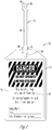
Fig. 1 is a perspective view of a tag and a lock; -
Fig. 2 is a top plan view of a tag; -
Fig. 3 is a perspective view of an injection molding machine; and -
Fig. 4 is a sectional view of the connection between a runner system of an injection molding machine and the mold cavity. - Referring to the figures, as an exemplary embodiment, a
tag 10 has aplate portion 12. Molded within theplate portion 12 is asheet 13 having a graphics and printedindicia 15. The graphics andindicia 15 may include a warning as well as information indicating the individual authorized to remove thetag 10
and/or a marking area. - Extending through the
plate 12 is aslot 14. While the slot is of any shape and size, preferred is a T-shaped slot. Extending outwardly from theplate portion 12 is an extension ortongue 16 having aneck portion 18. In an alternative embodiment, thetongue 16 andneck portion 18 oftag 10 are replaced with any integral wire tie known in the art. This integral wire tie includes one, two or more strands of a malleable wire covered in a plastic material, as is well known in the art, which extend outwardly from the top oftag 10. These malleable wires are then twisted or lockingly engaged with one another to attachtag 10. Alternatively, this integral wire tie includes a conventional zip-tie arrangement, as is well known in the art, having an extended tongue having locking notches thereon, and a locking head having a slot with a locking mechanism therein. The tongue of the zip-tie arrangement is then passed through the locking head of the zip-tie arrangement thereby lockingtag 10 in place. - The
tongue 16 also has alocking tip 20. Thelocking tip 20 is formed to be received within theslot 14 such that once thetip 20 passes through the slot and is twisted thetip 20 is retained by thetip 20 engaging a surface of theplate portion 12. Theneck 18 is made of a flexible material such that theneck 18 may be bent to permit thetip 20 to be received by and pass through theslot 14. Thelocking tip 20 has anaperture 22 adapted to receive alock 23, such as a conventional padlock. - In use, a
tag 10 is attached to a shipment, article, device, product or other object by way of bendingtongue 16 around a portion of the object so that thelocking tip 20 is received by and passes through theslot 14. In the embodiment shown in the drawings, theneck 18 is bent and twisted such that thetip 20 slides through thenarrow section 24 of the T-shaped slot 14. Once through theslot 14, when theneck 18 is permitted to untwist, theneck 18 is received in thetransverse section 26 of theslot 14, such that an edge of the tip engages a surface of theplate portion 12. Once thetip 20 is retained, should the user desire,lock 23 is inserted throughaperture 22 and locked in place. - In operation the body of
tag 10 which includesplate portion 12,tongue 16, andneck portion 18 is manufactured as a single continuous piece through an injection molding process. In a first step, granulated, powdered or liquefied plastic, rubber, thermoplastic, thermosetting plastic, or the like filler material is combined with a magnetically detectable additive which is also granulated, powdered or liquefied, or is otherwise in a non-dusting form such as pellets. In a second step the combined filler material and the magnetically detectable additive is operatively mixed and heated such that a homogeneous detectable material results. Alternatively, the filler material and magnetically detectable additive are individually heated to a liquefied form, and then combined with one another in a liquefied form and thereafter mixed to create a homogenous material. The resulting fluid or liquefied homogeneous combination of the filler material and magnetically detectable additive is then used in a manufacturing method, such as an injection molding process. - In one embodiment a sheet or
label 13 is added to an opened injection mold with graphics or printedindicia 15 facing away from the cavity of the mold. The injection mold is then closed and the fluid homogeneous filler material and magnetically detectable additive is injected through a nozzle into the cavity of the mold. The fluid homogenous material contacts the non-indicia side oflabel 13 and bonds therewith and solidifies to form a single functional unit. In certain applications, binding or gluing material is placed on the non-indicia, or cavity side of thelabel 13 to further promote adhesion of thelabel 13 to the signage. - The detectable additive is a magnetically detectable material such as any metallic or ferrous material. In one embodiment, detectable additive is PolyMag® material manufactured by Eriez Manufacturing Co., 2200 Asbury Road, Erie, PA 16506.
- In a preferred embodiment, the quantity of the magnetically detectable additive is extremely small. The quantity of detectable additive is between 1 % and 40% by weight of the mixed homogeneous detectable material, and preferably between 5% and 20% of the mixed homogeneous detectable material. The addition of the magnetically detectable additive visibly changes the color of the filler material. As an example, when the detectable additive is added to a white filler material the resulting product is somewhat grey in color. As another example, when the detectable additive is added to a red filler material the resulting product is a darker red or a somewhat maroon color. The resulting homogenous detectable mixture can further be pigmented any color through the addition of further coloring additives. Besides the detectable nature and somewhat darker color, the addition of the detectable additive does not otherwise affect the physical properties of the resulting product such as strength, melting point, etc.
- As one exemplary way of making a detectable signage is presented with reference to the parent application,
U.S. Patent Application Serial No. 12/766,286 filed on April 23, 2010 Figs. 3 and4 , aninjection molding assembly 110 is presented that has arunner system 112 that injects molten thermoplastic and magnetically detectable additive into amold cavity 114. Therunner system 112 has aninlet 116 and a system ofconduits 118 that provide a fluid flow of pressurized thermoplastics therethrough. Connecting the system ofconduits 118 with themold cavity 114 are a plurality of gate members ortunnel gates 120. - The
gate members 120 each have afirst section 122 that angles downwardly from theconduit 18 of therunner system 12 toward themold cavity 114. Thefirst section 122 tapers inwardly to a joint 124. Asecond section 126 of thetunnel gate 120 extends upwardly from the joint 124 toward themold cavity 114. In this manner, the first and second sections form a V-shape. Thesecond section 126, like the first section, tapers inwardly such that the diameter of the connection between thegate member 120 and theconduit 118 is greater than the connection between thegate member 120 and themold cavity 114. In addition, thesecond section 126 is at an angle such that the flow ofmaterial 128 into thesecond section 126 enters themold cavity 14 nearly perpendicular to the flow ofmaterial 128 through themold cavity 114. - Within the
mold cavity 114 is anindicia carrier 130 that has afirst edge 132. Theindicia carrier 130 in one embodiment is a label. Specifically,multiple indicia carriers 130 can be utilized including acarrier 130 that has man readable labels andcarriers 130 that have Radio Frequency Identification (RFID) that are non line of sight and machine readable only. - In operation, molten thermoplastic is injected through the
runner system 112 to the gate member ortunnel gate 120. The thermoplastic is displaced through thegate member 120 and into the mold cavity onto theedge 132 of theindicia carrier 130 nearly perpendicular to the planar surface of theindicia carrier 130. This has the effect of mechanically pinning theindicia carrier 130 into the proper position. Thereafter as the molten thermoplastic fills thecavity 114 air bubbles and wrinkles under theindicia carrier 130 are forced out and the finished product is smooth, bubble and wrinkle free such that the indicia carrier is 100% fused to the thermoplastic. Specifically, this manufacturing process exceeds all sanitation requirements. First, the entire mass of the product is brought to about 202°C (395F) and then over about 10,342 kPa (1,500 pounds) of pressure is exerted to force it into the tool. The product is then subjected to a packing pressure until it solidifies. - In one embodiment the tag, label, sign or the like has an
indicia carrier 130, both on the front and rear of the molded product such that a man readable indicia is on one side and RFID indicia is on the other side. In this embodiment the molten thermoplastic impinges on theedge 132 of afirst indicia carrier 130 and is then reflected backward onto theedge 132 of asecond indicia carrier 130 thereby pinning bothindicia carriers 130 within themold cavity 14 as best shown by the flow ofmaterial 128 inFig. 4 . Thus, a label utilizing a RFID is provided. - In an embodiment where ejector pins, as known in the art, are used and placed in close proximity to the
gate member 120, upon the finished part injection the tag, label, sign or the like formed in the mold is sheared off of theplastic runner system 112. This eliminates the need for operators to cut and trim individual tags or labels. - Thus provided is a method for manufacturing an injected molded product that utilizes
gate members 120 to provide a more efficient process and improved product. In addition, as compared to traditional tag manufacturing that requires reinforcement around an attachment hole by having the shear present this attachment method is eliminated. In addition, because theindicia carrier 130 is completely fused to the thermoplastic, moisture in high moisture environments is unable to get between theindicia carrier 130 and the molded body itself preventing contaminates from growing. Also, because theindicia carrier 130 is fused to the molded body, the indicia carrier is practically tamper proof. Any attempt to remove or modify theindicia carrier 130 is readily apparent to a casual observer. In addition, because injection molds for tags are easily manufactured with a bale or a loop of plastic that folds around an object and interlocks into a mating feature on the tag and can be used to include a padlock, additional safety is provided. In addition, a process for making labels having RFID is provided. - Thus, during the manufacturing of this product thermoplastics are heated within the barrel of an injection molding by the mechanical shear generated between the screw and the barrel. The temperature of the material exceeds about 199°C (390 degrees Fahrenheit) and is held under pressure until the next shot is required. At this time the material is subject to pressures exceeding about 12,411 kPa (1800 PSI) and is forced through the runner and gate systems. Additional heat is generated by the mechanical shear created by the forcing the material through the gates. After the cavity fills, a packing pressure is applied until thermoplastic solidifies and is ejected from the machine. These physical conditions exceed the standard operating procedures for auto clave thereby producing a sterile and safe product. Thus, at the very least all of the stated objectives have been met.
- Whereas the invention has been shown and described in connection with the embodiments thereof, it will be understood that many modifications, substitutions, and additions may be made which are within the intended broad scope of the following claims. From the foregoing, it can be seen that the present invention accomplishes at least all of the stated objective.
Claims (22)
- Signage (10) comprising:an in-mold plastic plate portion (12) having a slot (14);a flexible tongue(16) having a neck portion (18) that extends outwardly from the plate portion (12) and has a locking tip (20) extending from the neck portion (18); andthe locking tip (20) formed to be received by the slot (14);wherein the plastic plate portion (12) is made of a homogeneous mixture of a filler material and a magnetically detectable additive such that the signage is detectable by a metal detecting machine; andcharacterised by a label bonded to the homogeneous magnetically detectable mixture by placing the label having indicia into a cavity of an injection mold; and injecting the homogenous mixture into the cavity of the injection mold.
- The signage of claim 1 wherein the locking tip (20) has an aperture adapted to receive a locking mechanism.
- The signage of any one of claims 1 or 2 wherein the slot (14) is T-shaped.
- The signage of any one of the preceding claims wherein once the locking tip (20) passes through the slot (14) and is twisted the locking tip (20) is retained by a surface of the plate portion (12).
- The signage of any one of the preceding claims wherein the in-mold plastic plate portion (12) has a graphic sheet (13).
- The signage of any one of the preceding claims wherein the magnetically detectable additive is 5% to20% by weight of the homogeneous mixture of the filler material and the magnetically detectable additive.
- The signage of any one of the preceding claims wherein the signage is detectable by metallic detecting machines to a depth of 2.54 cm (1 inch).
- The signage of any one of the preceding claims, wherein the in-mold plastic plate portion, flexible tongue portion, and neck portion are a single continuous piece formed by a homogeneous combination of filler material and the magnetically detectable additive.
- The signage of any one of the preceding claims, wherein the magnetically detectable additive is between 1 % and 40% by weight of the mixed homogeneous detectable mixture.
- The signage of any one of the preceding claims wherein the filler material is plastic.
- The signage of any one of the preceding claims wherein the magnetically detectable additive visibly changes the color of the filler material.
- The signage of any one of the preceding claims further comprising an indicia carrier fused to the plastic plate.
- The signage of claim 12 wherein the indicia carrier is Radio Frequency Identification.
- The signage of claim 12 further comprising a second indicia carrier; wherein the second indicia carrier is man readable indicia.
- A method for making magnetically detectable signage (10) comprising the steps of:mixing a filler material with a magnetically detectable additive;heating the mixed filler material and the magnetically detectable additive to form a homogeneous mixture;placing a label having indicia positioned on one side into a cavity of an injection mold with the indicia facing away from the cavity; andinjecting the homogenous mixture into the cavity of the injection mold such that the homogeneous mixture bonds to the label forming magnetically detectable signage.
- The method of claim 15, comprising the steps of:heating a filler material and a magnetically detectable additive individually and then mixing the filler material with the magnetically detectable additive to form a homogeneous mixture;placing a label having indicia positioned on one side into a cavity of an injection mold with the indicia facing away from the cavity; andinjecting the homogeneous mixture into the cavity of the injection mold through a runner system to a gate member having a first and second section; anddisplacing the homogeneous mixture into the mold cavity through the first and second sections of the gate member into the cavity such that the homogeneous mixture bonds to the label forming magnetically detectable signage.
- The method of claim 15 or 16 wherein the magnetically detectable additive is 5% to 20% by weight of the homogeneous mixture.
- The method of any one of claims 15, 16 or 17 wherein the filler material is a plastic material.
- The method of claim any one of claims 15 to 18 wherein the magnetically detectable additive is in pellet form and/or wherein the filler material is in pellet form.
- The method of any one of claims 15 to 19 wherein the homogenous mixture fuses to the label thereby providing sanitary signage.
- The method of any one of claims 15 to 20, further comprising the step of forcing out all the bubbles and wrinkles from the homogeneous mixture.
- The method of any one of claims 15 to 21, wherein the second section is angled such that the homogeneous mixture is displaced onto an edge of the label nearly perpendicular to the planar surface of the label to hold the label in position against the mold cavity.
Applications Claiming Priority (3)
| Application Number | Priority Date | Filing Date | Title |
|---|---|---|---|
| US12/766,286 US7985364B1 (en) | 2010-04-23 | 2010-04-23 | Method of manufacturing an injection molded product |
| US12/904,470 US20110258896A1 (en) | 2010-04-23 | 2010-10-14 | Detectable signage apparatus and method of making the same |
| PCT/US2011/033434 WO2011133775A1 (en) | 2010-04-23 | 2011-04-21 | Detectable signage apparatus and method of making the same |
Publications (3)
| Publication Number | Publication Date |
|---|---|
| EP2561503A1 EP2561503A1 (en) | 2013-02-27 |
| EP2561503A4 EP2561503A4 (en) | 2013-11-06 |
| EP2561503B1 true EP2561503B1 (en) | 2018-10-31 |
Family
ID=44814559
Family Applications (1)
| Application Number | Title | Priority Date | Filing Date |
|---|---|---|---|
| EP11772710.7A Active EP2561503B1 (en) | 2010-04-23 | 2011-04-21 | Detectable signage apparatus and method of making the same |
Country Status (6)
| Country | Link |
|---|---|
| US (3) | US20110258896A1 (en) |
| EP (1) | EP2561503B1 (en) |
| CA (1) | CA2797243C (en) |
| ES (1) | ES2708923T3 (en) |
| MX (3) | MX350179B (en) |
| WO (1) | WO2011133775A1 (en) |
Families Citing this family (6)
| Publication number | Priority date | Publication date | Assignee | Title |
|---|---|---|---|---|
| US10078974B2 (en) * | 2014-05-01 | 2018-09-18 | James W. Walley, JR. | Color coding system for PVC pipes and couplings |
| KR101822565B1 (en) * | 2016-02-26 | 2018-01-26 | 서울과학기술대학교 산학협력단 | Injection molded lens using hot runner |
| IT201600094922A1 (en) * | 2016-09-21 | 2018-03-21 | Punto 2 S R L | METHOD FOR THE REALIZATION, RECOGNITION, IDENTIFICATION, READING AND TRACEABILITY OF A SEAL OR LABEL, SEAL OR LABEL AND APPARATUS FOR RECOGNITION, IDENTIFICATION, READING AND TRACEABILITY OF SUCH SEAL OR LABEL |
| US10325529B1 (en) * | 2018-02-13 | 2019-06-18 | Todd Kuhn | Interactive warning systems and methods |
| US11776434B2 (en) * | 2018-03-19 | 2023-10-03 | DRM Specialties, LLC | Method and apparatus for avoidance of damage to concealed mechanical systems such as plumbing and the like |
| DE102019130175A1 (en) * | 2019-11-08 | 2021-05-12 | Hellermanntyton Gmbh | Injection molding of a component, such as a cable holder, with an integrated wireless identification film |
Citations (1)
| Publication number | Priority date | Publication date | Assignee | Title |
|---|---|---|---|---|
| US20030000052A1 (en) * | 2000-05-04 | 2003-01-02 | Dossett Larry R. | Product stocking method and device |
Family Cites Families (40)
| Publication number | Priority date | Publication date | Assignee | Title |
|---|---|---|---|---|
| US1434312A (en) * | 1922-04-01 | 1922-10-31 | John A Penney | Hoop |
| US2016059A (en) * | 1934-01-04 | 1935-10-01 | Frederick A Stevens | Tag |
| US2359148A (en) * | 1941-11-19 | 1944-09-26 | Samuel Friedman | Wrist watch strap |
| US3093865A (en) | 1960-05-16 | 1963-06-18 | Phillips Petroleum Co | Injection molding of plastic materials |
| US3352040A (en) * | 1965-10-23 | 1967-11-14 | Javkin Simon | Luggage tag |
| US3550295A (en) * | 1968-12-10 | 1970-12-29 | Irving U Young | Baggage tag |
| CA1011516A (en) | 1973-07-13 | 1977-06-07 | Du Pont Of Canada Limited | Balanced runner system for injection moulding apparatus |
| US3837101A (en) * | 1973-07-18 | 1974-09-24 | I Young | Baggage tags |
| US3913179A (en) * | 1974-05-10 | 1975-10-21 | Jhoon Goo Rhee | Tie straps |
| US3961431A (en) * | 1975-09-22 | 1976-06-08 | Conversion Caddy Co. | Luggage tag |
| US4427618A (en) | 1981-01-30 | 1984-01-24 | Sorensen Jens Ole | Inclined insulated runner multicavity injection molding |
| US4570368A (en) * | 1985-03-25 | 1986-02-18 | Economy Label Sales, Inc. | Label for plants and nursery stock |
| US4891399A (en) * | 1986-10-28 | 1990-01-02 | Calp Corporation | Thermoplastic resin-based molding composition |
| USRE37506E1 (en) * | 1988-12-02 | 2002-01-15 | Jens Ole Sorensen | Method for molding article in plurality of colors |
| CA2020276A1 (en) * | 1989-07-05 | 1991-01-06 | Terutaka Sano | Polybutylene terephthalate resin molded article having pictorial pattern formed thereon and process for preparation thereof |
| US5311690A (en) * | 1991-09-03 | 1994-05-17 | Batten Douglas R | Identification tag |
| US5604006A (en) * | 1992-01-24 | 1997-02-18 | Cascade Engineering | Label inmolding process and article of manufacture produced therefrom |
| US5916047A (en) | 1994-02-03 | 1999-06-29 | Huffy Corporation | Portable basketball goal support system with separate ballast tank |
| US5980400A (en) | 1994-02-03 | 1999-11-09 | Huffy Corporation | Compression molded basketball components with inmold graphics |
| US5804117A (en) | 1994-04-05 | 1998-09-08 | Toyoda Gosei Co., Ltd. | Molding method for resin articles |
| US5687455A (en) * | 1996-01-18 | 1997-11-18 | Alexander; Gary E. | Releasable circular fastener |
| US6004231A (en) | 1996-01-31 | 1999-12-21 | Huffy Corporation | Molded frame backboard assembly and method of making same |
| NL1002696C2 (en) * | 1996-03-25 | 1997-09-26 | Simco Nederland | Method and device for manufacturing an injection molded article, as well as an article manufactured therewith. |
| JPH1058490A (en) | 1996-08-27 | 1998-03-03 | Sakura Plast:Kk | Mold for injection molding |
| US6401304B1 (en) * | 1999-05-06 | 2002-06-11 | Goody Products, Inc. | Product stocking method and device |
| US6276029B1 (en) * | 1999-08-27 | 2001-08-21 | J.A.M. Plastics, Inc. | Neck strap |
| US6623677B1 (en) | 2000-07-21 | 2003-09-23 | Bayer Corporation | Decorated article made by film insert molding |
| FI20002038A7 (en) * | 2000-09-15 | 2002-03-16 | Nokia Corp | Decorated injection molded product and method for making same |
| US7514131B2 (en) * | 2002-11-22 | 2009-04-07 | Yupo Corporation | In-mold label with separable part |
| US6962014B2 (en) * | 2003-04-01 | 2005-11-08 | Mccabe Suellyn A | Removable cable labeling device |
| US20050268509A1 (en) * | 2004-06-03 | 2005-12-08 | Lewis Mark W | Vehicle locator and identification card |
| DE102004041833A1 (en) | 2004-08-27 | 2006-03-02 | Leonhard Kurz Gmbh & Co. Kg | Decorated injection molded article, method of making a decorated injection molded article, and transfer sheet for use in such method |
| AU2006263553B2 (en) * | 2005-06-29 | 2010-05-27 | Eidgenossische Technische Hochschule Zurich | Unique label for identification or security system |
| US7624525B2 (en) * | 2006-03-20 | 2009-12-01 | Lomont Molding, Inc. | Lock out tag |
| US7871693B2 (en) * | 2006-04-05 | 2011-01-18 | Thomas & Betts International, Inc. | Detectable cable tie |
| US7523576B1 (en) * | 2006-05-01 | 2009-04-28 | The Meyers Printing Companies, Inc. | Point-of-purchase promotional article |
| TWI422498B (en) * | 2008-04-02 | 2014-01-11 | Sicpa Holding Sa | Identification and authentication using liquid crystal material markings |
| GB2465161A (en) * | 2008-11-05 | 2010-05-12 | First Major Assets Ltd | Matrix display tag |
| CN201549141U (en) * | 2009-06-30 | 2010-08-11 | 王旭飞 | Label type cable tie |
| CN202749031U (en) * | 2012-06-13 | 2013-02-20 | 北京瑞芯谷科技有限公司 | Underground cable tie |
-
2010
- 2010-10-14 US US12/904,470 patent/US20110258896A1/en not_active Abandoned
-
2011
- 2011-04-21 MX MX2015004301A patent/MX350179B/en unknown
- 2011-04-21 ES ES11772710T patent/ES2708923T3/en active Active
- 2011-04-21 EP EP11772710.7A patent/EP2561503B1/en active Active
- 2011-04-21 CA CA2797243A patent/CA2797243C/en active Active
- 2011-04-21 MX MX2015004300A patent/MX350178B/en unknown
- 2011-04-21 WO PCT/US2011/033434 patent/WO2011133775A1/en not_active Ceased
- 2011-04-21 MX MX2012012358A patent/MX2012012358A/en active IP Right Grant
-
2012
- 2012-03-29 US US13/434,329 patent/US8636934B2/en active Active
- 2012-10-29 US US13/662,954 patent/US20130047407A1/en not_active Abandoned
Patent Citations (1)
| Publication number | Priority date | Publication date | Assignee | Title |
|---|---|---|---|---|
| US20030000052A1 (en) * | 2000-05-04 | 2003-01-02 | Dossett Larry R. | Product stocking method and device |
Also Published As
| Publication number | Publication date |
|---|---|
| CA2797243A1 (en) | 2011-10-27 |
| EP2561503A1 (en) | 2013-02-27 |
| MX350178B (en) | 2017-08-29 |
| ES2708923T3 (en) | 2019-04-12 |
| WO2011133775A1 (en) | 2011-10-27 |
| MX350179B (en) | 2017-08-29 |
| MX2012012358A (en) | 2013-03-07 |
| EP2561503A4 (en) | 2013-11-06 |
| US8636934B2 (en) | 2014-01-28 |
| CA2797243C (en) | 2019-02-26 |
| US20110258896A1 (en) | 2011-10-27 |
| US20130047407A1 (en) | 2013-02-28 |
| US20120192471A1 (en) | 2012-08-02 |
Similar Documents
| Publication | Publication Date | Title |
|---|---|---|
| US8636934B2 (en) | Method of making detectable signage | |
| US20120279023A1 (en) | Plastic Fastening Device Comprising a Recycled Thermoplastic Resin | |
| CA1293852C (en) | Paper-laminated pliable closure for flexible bags | |
| DE69806912T2 (en) | METHOD FOR ENCLOSING AN ELECTRONIC LABEL IN THE WALL OF A THERMOFORMED OBJECT, AND PREPARATION DEVICE FOR THIS METHOD | |
| US8120485B2 (en) | Articles containing chipless radio frequency identification elements | |
| EP2386106B1 (en) | Fastening assembly fabricated from a water-soluble material | |
| US9262710B2 (en) | Product identification tag and associated methods | |
| WO2008000253A1 (en) | Method for the production of a container, and container for storing and transporting piece goods and bulk material | |
| EP2231379A1 (en) | Method for molding an object containing a radio frequency identification tag | |
| US20080150701A1 (en) | Method and apparatus for forming plastics with integral RFID devices | |
| WO2015073964A1 (en) | Rfid enabled container | |
| US20150028219A1 (en) | Workpiece with marking | |
| EP2949441A1 (en) | Container | |
| EP2024245A1 (en) | Reclosable package with an rfid tag | |
| US7985364B1 (en) | Method of manufacturing an injection molded product | |
| US20200071774A1 (en) | Systems and Methods for Securing Anti-Tamper Label and Tape Adhesive Chemistry with Molecular Taggants | |
| JP4647971B2 (en) | Sandwich moldings | |
| US20060266087A1 (en) | Locking device | |
| CN212655729U (en) | Biodegradable anti-theft opening sealing box adhesive tape | |
| DE102005035899A1 (en) | Object produced in two-component injection method has inlaid component located between components in parting plane, wherein inlaid component may be label, sticker, rigid object, metal component, or electrical functional film | |
| CN215012557U (en) | Traceability ear tag for identifying yak meat quality | |
| EP3720677B1 (en) | Method for remolding thermoplastic trays | |
| DE202006010214U1 (en) | Trolley container for bulk materials, includes radio frequency identification transponder label bonded integrally with container using in-mold process | |
| US20220005381A1 (en) | Anti-microbial security seals | |
| CN208344972U (en) | A kind of plastic sealing strip of tape identification scale |
Legal Events
| Date | Code | Title | Description |
|---|---|---|---|
| PUAI | Public reference made under article 153(3) epc to a published international application that has entered the european phase |
Free format text: ORIGINAL CODE: 0009012 |
|
| 17P | Request for examination filed |
Effective date: 20121023 |
|
| AK | Designated contracting states |
Kind code of ref document: A1 Designated state(s): AL AT BE BG CH CY CZ DE DK EE ES FI FR GB GR HR HU IE IS IT LI LT LU LV MC MK MT NL NO PL PT RO RS SE SI SK SM TR |
|
| DAX | Request for extension of the european patent (deleted) | ||
| A4 | Supplementary search report drawn up and despatched |
Effective date: 20131004 |
|
| RIC1 | Information provided on ipc code assigned before grant |
Ipc: G09F 3/02 20060101AFI20130927BHEP Ipc: B29C 45/14 20060101ALI20130927BHEP Ipc: B29C 45/27 20060101ALI20130927BHEP Ipc: B29C 45/00 20060101ALN20130927BHEP |
|
| 17Q | First examination report despatched |
Effective date: 20140526 |
|
| RIN1 | Information on inventor provided before grant (corrected) |
Inventor name: FRANK, CARL Inventor name: BENDER, JASON Inventor name: WATSON, VIRGIL ALLEN |
|
| RIN1 | Information on inventor provided before grant (corrected) |
Inventor name: BENDER, JASON Inventor name: FRANK, CARL Inventor name: WATSON, VIRGIL ALLEN |
|
| STAA | Information on the status of an ep patent application or granted ep patent |
Free format text: STATUS: EXAMINATION IS IN PROGRESS |
|
| REG | Reference to a national code |
Ref country code: DE Ref legal event code: R079 Ref document number: 602011053457 Country of ref document: DE Free format text: PREVIOUS MAIN CLASS: G09F0003140000 Ipc: G09F0003020000 |
|
| RIC1 | Information provided on ipc code assigned before grant |
Ipc: G09F 3/02 20060101AFI20180321BHEP Ipc: B29C 45/27 20060101ALI20180321BHEP Ipc: B29C 45/14 20060101ALI20180321BHEP Ipc: B29C 45/00 20060101ALN20180321BHEP |
|
| GRAP | Despatch of communication of intention to grant a patent |
Free format text: ORIGINAL CODE: EPIDOSNIGR1 |
|
| STAA | Information on the status of an ep patent application or granted ep patent |
Free format text: STATUS: GRANT OF PATENT IS INTENDED |
|
| RIC1 | Information provided on ipc code assigned before grant |
Ipc: B29C 45/00 20060101ALN20180417BHEP Ipc: B29C 45/14 20060101ALI20180417BHEP Ipc: G09F 3/02 20060101AFI20180417BHEP Ipc: B29C 45/27 20060101ALI20180417BHEP |
|
| INTG | Intention to grant announced |
Effective date: 20180508 |
|
| RAP1 | Party data changed (applicant data changed or rights of an application transferred) |
Owner name: LOMONT MOLDING, INC. |
|
| GRAS | Grant fee paid |
Free format text: ORIGINAL CODE: EPIDOSNIGR3 |
|
| GRAA | (expected) grant |
Free format text: ORIGINAL CODE: 0009210 |
|
| STAA | Information on the status of an ep patent application or granted ep patent |
Free format text: STATUS: THE PATENT HAS BEEN GRANTED |
|
| AK | Designated contracting states |
Kind code of ref document: B1 Designated state(s): AL AT BE BG CH CY CZ DE DK EE ES FI FR GB GR HR HU IE IS IT LI LT LU LV MC MK MT NL NO PL PT RO RS SE SI SK SM TR |
|
| REG | Reference to a national code |
Ref country code: CH Ref legal event code: EP Ref country code: GB Ref legal event code: FG4D |
|
| REG | Reference to a national code |
Ref country code: AT Ref legal event code: REF Ref document number: 1060342 Country of ref document: AT Kind code of ref document: T Effective date: 20181115 |
|
| REG | Reference to a national code |
Ref country code: DE Ref legal event code: R096 Ref document number: 602011053457 Country of ref document: DE |
|
| REG | Reference to a national code |
Ref country code: IE Ref legal event code: FG4D |
|
| REG | Reference to a national code |
Ref country code: NL Ref legal event code: MP Effective date: 20181031 |
|
| REG | Reference to a national code |
Ref country code: LT Ref legal event code: MG4D |
|
| REG | Reference to a national code |
Ref country code: ES Ref legal event code: FG2A Ref document number: 2708923 Country of ref document: ES Kind code of ref document: T3 Effective date: 20190412 |
|
| REG | Reference to a national code |
Ref country code: AT Ref legal event code: MK05 Ref document number: 1060342 Country of ref document: AT Kind code of ref document: T Effective date: 20181031 |
|
| PG25 | Lapsed in a contracting state [announced via postgrant information from national office to epo] |
Ref country code: AT Free format text: LAPSE BECAUSE OF FAILURE TO SUBMIT A TRANSLATION OF THE DESCRIPTION OR TO PAY THE FEE WITHIN THE PRESCRIBED TIME-LIMIT Effective date: 20181031 Ref country code: LV Free format text: LAPSE BECAUSE OF FAILURE TO SUBMIT A TRANSLATION OF THE DESCRIPTION OR TO PAY THE FEE WITHIN THE PRESCRIBED TIME-LIMIT Effective date: 20181031 Ref country code: PL Free format text: LAPSE BECAUSE OF FAILURE TO SUBMIT A TRANSLATION OF THE DESCRIPTION OR TO PAY THE FEE WITHIN THE PRESCRIBED TIME-LIMIT Effective date: 20181031 Ref country code: HR Free format text: LAPSE BECAUSE OF FAILURE TO SUBMIT A TRANSLATION OF THE DESCRIPTION OR TO PAY THE FEE WITHIN THE PRESCRIBED TIME-LIMIT Effective date: 20181031 Ref country code: IS Free format text: LAPSE BECAUSE OF FAILURE TO SUBMIT A TRANSLATION OF THE DESCRIPTION OR TO PAY THE FEE WITHIN THE PRESCRIBED TIME-LIMIT Effective date: 20190228 Ref country code: BG Free format text: LAPSE BECAUSE OF FAILURE TO SUBMIT A TRANSLATION OF THE DESCRIPTION OR TO PAY THE FEE WITHIN THE PRESCRIBED TIME-LIMIT Effective date: 20190131 Ref country code: NO Free format text: LAPSE BECAUSE OF FAILURE TO SUBMIT A TRANSLATION OF THE DESCRIPTION OR TO PAY THE FEE WITHIN THE PRESCRIBED TIME-LIMIT Effective date: 20190131 Ref country code: LT Free format text: LAPSE BECAUSE OF FAILURE TO SUBMIT A TRANSLATION OF THE DESCRIPTION OR TO PAY THE FEE WITHIN THE PRESCRIBED TIME-LIMIT Effective date: 20181031 Ref country code: FI Free format text: LAPSE BECAUSE OF FAILURE TO SUBMIT A TRANSLATION OF THE DESCRIPTION OR TO PAY THE FEE WITHIN THE PRESCRIBED TIME-LIMIT Effective date: 20181031 |
|
| PG25 | Lapsed in a contracting state [announced via postgrant information from national office to epo] |
Ref country code: PT Free format text: LAPSE BECAUSE OF FAILURE TO SUBMIT A TRANSLATION OF THE DESCRIPTION OR TO PAY THE FEE WITHIN THE PRESCRIBED TIME-LIMIT Effective date: 20190301 Ref country code: SE Free format text: LAPSE BECAUSE OF FAILURE TO SUBMIT A TRANSLATION OF THE DESCRIPTION OR TO PAY THE FEE WITHIN THE PRESCRIBED TIME-LIMIT Effective date: 20181031 Ref country code: GR Free format text: LAPSE BECAUSE OF FAILURE TO SUBMIT A TRANSLATION OF THE DESCRIPTION OR TO PAY THE FEE WITHIN THE PRESCRIBED TIME-LIMIT Effective date: 20190201 Ref country code: RS Free format text: LAPSE BECAUSE OF FAILURE TO SUBMIT A TRANSLATION OF THE DESCRIPTION OR TO PAY THE FEE WITHIN THE PRESCRIBED TIME-LIMIT Effective date: 20181031 Ref country code: AL Free format text: LAPSE BECAUSE OF FAILURE TO SUBMIT A TRANSLATION OF THE DESCRIPTION OR TO PAY THE FEE WITHIN THE PRESCRIBED TIME-LIMIT Effective date: 20181031 Ref country code: NL Free format text: LAPSE BECAUSE OF FAILURE TO SUBMIT A TRANSLATION OF THE DESCRIPTION OR TO PAY THE FEE WITHIN THE PRESCRIBED TIME-LIMIT Effective date: 20181031 |
|
| PG25 | Lapsed in a contracting state [announced via postgrant information from national office to epo] |
Ref country code: DK Free format text: LAPSE BECAUSE OF FAILURE TO SUBMIT A TRANSLATION OF THE DESCRIPTION OR TO PAY THE FEE WITHIN THE PRESCRIBED TIME-LIMIT Effective date: 20181031 Ref country code: CZ Free format text: LAPSE BECAUSE OF FAILURE TO SUBMIT A TRANSLATION OF THE DESCRIPTION OR TO PAY THE FEE WITHIN THE PRESCRIBED TIME-LIMIT Effective date: 20181031 |
|
| REG | Reference to a national code |
Ref country code: DE Ref legal event code: R097 Ref document number: 602011053457 Country of ref document: DE |
|
| PG25 | Lapsed in a contracting state [announced via postgrant information from national office to epo] |
Ref country code: RO Free format text: LAPSE BECAUSE OF FAILURE TO SUBMIT A TRANSLATION OF THE DESCRIPTION OR TO PAY THE FEE WITHIN THE PRESCRIBED TIME-LIMIT Effective date: 20181031 Ref country code: EE Free format text: LAPSE BECAUSE OF FAILURE TO SUBMIT A TRANSLATION OF THE DESCRIPTION OR TO PAY THE FEE WITHIN THE PRESCRIBED TIME-LIMIT Effective date: 20181031 Ref country code: SM Free format text: LAPSE BECAUSE OF FAILURE TO SUBMIT A TRANSLATION OF THE DESCRIPTION OR TO PAY THE FEE WITHIN THE PRESCRIBED TIME-LIMIT Effective date: 20181031 Ref country code: SK Free format text: LAPSE BECAUSE OF FAILURE TO SUBMIT A TRANSLATION OF THE DESCRIPTION OR TO PAY THE FEE WITHIN THE PRESCRIBED TIME-LIMIT Effective date: 20181031 |
|
| PLBE | No opposition filed within time limit |
Free format text: ORIGINAL CODE: 0009261 |
|
| STAA | Information on the status of an ep patent application or granted ep patent |
Free format text: STATUS: NO OPPOSITION FILED WITHIN TIME LIMIT |
|
| 26N | No opposition filed |
Effective date: 20190801 |
|
| PG25 | Lapsed in a contracting state [announced via postgrant information from national office to epo] |
Ref country code: SI Free format text: LAPSE BECAUSE OF FAILURE TO SUBMIT A TRANSLATION OF THE DESCRIPTION OR TO PAY THE FEE WITHIN THE PRESCRIBED TIME-LIMIT Effective date: 20181031 |
|
| REG | Reference to a national code |
Ref country code: CH Ref legal event code: PL |
|
| REG | Reference to a national code |
Ref country code: BE Ref legal event code: MM Effective date: 20190430 |
|
| PG25 | Lapsed in a contracting state [announced via postgrant information from national office to epo] |
Ref country code: LU Free format text: LAPSE BECAUSE OF NON-PAYMENT OF DUE FEES Effective date: 20190421 Ref country code: MC Free format text: LAPSE BECAUSE OF FAILURE TO SUBMIT A TRANSLATION OF THE DESCRIPTION OR TO PAY THE FEE WITHIN THE PRESCRIBED TIME-LIMIT Effective date: 20181031 |
|
| PG25 | Lapsed in a contracting state [announced via postgrant information from national office to epo] |
Ref country code: LI Free format text: LAPSE BECAUSE OF NON-PAYMENT OF DUE FEES Effective date: 20190430 Ref country code: CH Free format text: LAPSE BECAUSE OF NON-PAYMENT OF DUE FEES Effective date: 20190430 |
|
| PG25 | Lapsed in a contracting state [announced via postgrant information from national office to epo] |
Ref country code: BE Free format text: LAPSE BECAUSE OF NON-PAYMENT OF DUE FEES Effective date: 20190430 |
|
| PG25 | Lapsed in a contracting state [announced via postgrant information from national office to epo] |
Ref country code: TR Free format text: LAPSE BECAUSE OF FAILURE TO SUBMIT A TRANSLATION OF THE DESCRIPTION OR TO PAY THE FEE WITHIN THE PRESCRIBED TIME-LIMIT Effective date: 20181031 |
|
| PG25 | Lapsed in a contracting state [announced via postgrant information from national office to epo] |
Ref country code: IE Free format text: LAPSE BECAUSE OF NON-PAYMENT OF DUE FEES Effective date: 20190421 |
|
| PG25 | Lapsed in a contracting state [announced via postgrant information from national office to epo] |
Ref country code: CY Free format text: LAPSE BECAUSE OF FAILURE TO SUBMIT A TRANSLATION OF THE DESCRIPTION OR TO PAY THE FEE WITHIN THE PRESCRIBED TIME-LIMIT Effective date: 20181031 |
|
| PG25 | Lapsed in a contracting state [announced via postgrant information from national office to epo] |
Ref country code: MT Free format text: LAPSE BECAUSE OF FAILURE TO SUBMIT A TRANSLATION OF THE DESCRIPTION OR TO PAY THE FEE WITHIN THE PRESCRIBED TIME-LIMIT Effective date: 20181031 Ref country code: HU Free format text: LAPSE BECAUSE OF FAILURE TO SUBMIT A TRANSLATION OF THE DESCRIPTION OR TO PAY THE FEE WITHIN THE PRESCRIBED TIME-LIMIT; INVALID AB INITIO Effective date: 20110421 |
|
| PG25 | Lapsed in a contracting state [announced via postgrant information from national office to epo] |
Ref country code: MK Free format text: LAPSE BECAUSE OF FAILURE TO SUBMIT A TRANSLATION OF THE DESCRIPTION OR TO PAY THE FEE WITHIN THE PRESCRIBED TIME-LIMIT Effective date: 20181031 |
|
| P01 | Opt-out of the competence of the unified patent court (upc) registered |
Effective date: 20230602 |
|
| P02 | Opt-out of the competence of the unified patent court (upc) changed |
Effective date: 20230619 |
|
| PGFP | Annual fee paid to national office [announced via postgrant information from national office to epo] |
Ref country code: DE Payment date: 20250225 Year of fee payment: 15 |
|
| PGFP | Annual fee paid to national office [announced via postgrant information from national office to epo] |
Ref country code: ES Payment date: 20250509 Year of fee payment: 15 |
|
| PGFP | Annual fee paid to national office [announced via postgrant information from national office to epo] |
Ref country code: GB Payment date: 20260303 Year of fee payment: 16 |
|
| PGFP | Annual fee paid to national office [announced via postgrant information from national office to epo] |
Ref country code: IT Payment date: 20260320 Year of fee payment: 16 |
|
| PGFP | Annual fee paid to national office [announced via postgrant information from national office to epo] |
Ref country code: FR Payment date: 20260209 Year of fee payment: 16 |