EP2561375B1 - Method for designing coil systems for generation of magnetic fields of desired geometry, a magnetic resonance imaging or magnetoencephalography apparatus with a coil assembly and a computer program - Google Patents
Method for designing coil systems for generation of magnetic fields of desired geometry, a magnetic resonance imaging or magnetoencephalography apparatus with a coil assembly and a computer program Download PDFInfo
- Publication number
- EP2561375B1 EP2561375B1 EP11758880.6A EP11758880A EP2561375B1 EP 2561375 B1 EP2561375 B1 EP 2561375B1 EP 11758880 A EP11758880 A EP 11758880A EP 2561375 B1 EP2561375 B1 EP 2561375B1
- Authority
- EP
- European Patent Office
- Prior art keywords
- field
- components
- coils
- magnetic field
- matrix
- Prior art date
- Legal status (The legal status is an assumption and is not a legal conclusion. Google has not performed a legal analysis and makes no representation as to the accuracy of the status listed.)
- Active
Links
Images

Classifications
-
- G—PHYSICS
- G01—MEASURING; TESTING
- G01R—MEASURING ELECTRIC VARIABLES; MEASURING MAGNETIC VARIABLES
- G01R33/00—Arrangements or instruments for measuring magnetic variables
- G01R33/20—Arrangements or instruments for measuring magnetic variables involving magnetic resonance
-
- G—PHYSICS
- G06—COMPUTING OR CALCULATING; COUNTING
- G06F—ELECTRIC DIGITAL DATA PROCESSING
- G06F17/00—Digital computing or data processing equipment or methods, specially adapted for specific functions
- G06F17/10—Complex mathematical operations
- G06F17/11—Complex mathematical operations for solving equations, e.g. nonlinear equations, general mathematical optimization problems
- G06F17/12—Simultaneous equations, e.g. systems of linear equations
-
- A—HUMAN NECESSITIES
- A61—MEDICAL OR VETERINARY SCIENCE; HYGIENE
- A61B—DIAGNOSIS; SURGERY; IDENTIFICATION
- A61B5/00—Measuring for diagnostic purposes; Identification of persons
- A61B5/0033—Features or image-related aspects of imaging apparatus, e.g. for MRI, optical tomography or impedance tomography apparatus; Arrangements of imaging apparatus in a room
- A61B5/0035—Features or image-related aspects of imaging apparatus, e.g. for MRI, optical tomography or impedance tomography apparatus; Arrangements of imaging apparatus in a room adapted for acquisition of images from more than one imaging mode, e.g. combining MRI and optical tomography
-
- A—HUMAN NECESSITIES
- A61—MEDICAL OR VETERINARY SCIENCE; HYGIENE
- A61B—DIAGNOSIS; SURGERY; IDENTIFICATION
- A61B5/00—Measuring for diagnostic purposes; Identification of persons
- A61B5/24—Detecting, measuring or recording bioelectric or biomagnetic signals of the body or parts thereof
- A61B5/242—Detecting biomagnetic fields, e.g. magnetic fields produced by bioelectric currents
- A61B5/245—Detecting biomagnetic fields, e.g. magnetic fields produced by bioelectric currents specially adapted for magnetoencephalographic [MEG] signals
-
- G—PHYSICS
- G01—MEASURING; TESTING
- G01R—MEASURING ELECTRIC VARIABLES; MEASURING MAGNETIC VARIABLES
- G01R33/00—Arrangements or instruments for measuring magnetic variables
- G01R33/02—Measuring direction or magnitude of magnetic fields or magnetic flux
- G01R33/025—Compensating stray fields
-
- G—PHYSICS
- G01—MEASURING; TESTING
- G01R—MEASURING ELECTRIC VARIABLES; MEASURING MAGNETIC VARIABLES
- G01R33/00—Arrangements or instruments for measuring magnetic variables
- G01R33/20—Arrangements or instruments for measuring magnetic variables involving magnetic resonance
- G01R33/28—Details of apparatus provided for in groups G01R33/44 - G01R33/64
-
- G—PHYSICS
- G01—MEASURING; TESTING
- G01R—MEASURING ELECTRIC VARIABLES; MEASURING MAGNETIC VARIABLES
- G01R33/00—Arrangements or instruments for measuring magnetic variables
- G01R33/20—Arrangements or instruments for measuring magnetic variables involving magnetic resonance
- G01R33/28—Details of apparatus provided for in groups G01R33/44 - G01R33/64
- G01R33/38—Systems for generation, homogenisation or stabilisation of the main or gradient magnetic field
- G01R33/381—Systems for generation, homogenisation or stabilisation of the main or gradient magnetic field using electromagnets
-
- G—PHYSICS
- G01—MEASURING; TESTING
- G01R—MEASURING ELECTRIC VARIABLES; MEASURING MAGNETIC VARIABLES
- G01R33/00—Arrangements or instruments for measuring magnetic variables
- G01R33/20—Arrangements or instruments for measuring magnetic variables involving magnetic resonance
- G01R33/28—Details of apparatus provided for in groups G01R33/44 - G01R33/64
- G01R33/38—Systems for generation, homogenisation or stabilisation of the main or gradient magnetic field
- G01R33/385—Systems for generation, homogenisation or stabilisation of the main or gradient magnetic field using gradient magnetic field coils
-
- G—PHYSICS
- G01—MEASURING; TESTING
- G01R—MEASURING ELECTRIC VARIABLES; MEASURING MAGNETIC VARIABLES
- G01R33/00—Arrangements or instruments for measuring magnetic variables
- G01R33/20—Arrangements or instruments for measuring magnetic variables involving magnetic resonance
- G01R33/28—Details of apparatus provided for in groups G01R33/44 - G01R33/64
- G01R33/38—Systems for generation, homogenisation or stabilisation of the main or gradient magnetic field
- G01R33/387—Compensation of inhomogeneities
- G01R33/3875—Compensation of inhomogeneities using correction coil assemblies, e.g. active shimming
-
- G—PHYSICS
- G01—MEASURING; TESTING
- G01R—MEASURING ELECTRIC VARIABLES; MEASURING MAGNETIC VARIABLES
- G01R33/00—Arrangements or instruments for measuring magnetic variables
- G01R33/20—Arrangements or instruments for measuring magnetic variables involving magnetic resonance
- G01R33/28—Details of apparatus provided for in groups G01R33/44 - G01R33/64
- G01R33/42—Screening
- G01R33/421—Screening of main or gradient magnetic field
- G01R33/4215—Screening of main or gradient magnetic field of the gradient magnetic field, e.g. using passive or active shielding of the gradient magnetic field
-
- G—PHYSICS
- G01—MEASURING; TESTING
- G01R—MEASURING ELECTRIC VARIABLES; MEASURING MAGNETIC VARIABLES
- G01R33/00—Arrangements or instruments for measuring magnetic variables
- G01R33/20—Arrangements or instruments for measuring magnetic variables involving magnetic resonance
- G01R33/44—Arrangements or instruments for measuring magnetic variables involving magnetic resonance using nuclear magnetic resonance [NMR]
- G01R33/48—NMR imaging systems
- G01R33/4808—Multimodal MR, e.g. MR combined with positron emission tomography [PET], MR combined with ultrasound or MR combined with computed tomography [CT]
Definitions
- the invention relates to magnetic imaging technologies and specifically to creation of magnetic fields of specified, geometrically precise shape over a large volume in space.
- Magnetic fields of precise geometry are needed in medical magnetic imaging applications, like magnetic resonance imaging (MRI) and magnetoencephalography (MEG). Recently, also combination of the two imaging techniques has been proposed (" Microtesla MRI on the human brain combined with MEG”, Vadim S. Zotev et al, Journ. Mag. Res. 194, pp 115-120, 2008 ).
- the part of the human body that is studied is exposed to a uniform magnetic field, and to gradients of the field for decoding of the spatial information contained in the MRI signal.
- the geometry of the measuring field essentially contributes to the signal quality and geometric precision of the resulting MRI image.
- An ideal measuring field is free of field derivatives higher than first.
- the very weak magnetic signals resulting from the functioning of the human brain are recorded by sensors located around the head.
- One of the main problems in this technique is the protection of the measuring device against the environmental magnetic interference the strength of which may exceed the signals of interest by seven to eight orders of magnitude.
- This magnetic shielding problem can be solved by active compensation methods that counteract the interference using coil systems tailored to produce counter fields that very precisely match the geometry of the interference fields (see WO2005/078467 ).
- the interference fields in a typical MEG recording environment are relatively uniform and smooth.
- Smooth means here that the fields comprise of spatially uniform field components and only low order spatial derivatives of these components. Spatial derivatives higher than first order, say, are of very small amplitude in the interference. This is so because these fields arise from sources tens of meters away from the recording device, and are additionally smoothed by the magnetically shielding room (MSR) housing the MEG device. Therefore, the fields used to counteract these interference fields in an active compensation arrangement must also be smooth and tailored to optimally match the interference field geometry. This enables maximal compensation of the interference over relatively large volume of the size of the human head.
- the coil systems In both MRI and MEG methods the coil systems must be located relatively close to the measuring device. This way the currents needed to create the measuring and counteracting fields stay reasonably small. Furthermore, if a feedback principle is used for the active compensation the compensation coils must necessarily be inside the MSR ( WO2005/078467 ). Placing the coils outside of the MSR would cause extra delay and lead to unstable feedback loop.
- a well-known, elementary example toward the solution of this kind of coil design problem are the so called Helmholz and Maxwell pairs:
- Helmholz and Maxwell pairs By properly choosing the distance between two circular, coaxial coils of same size one can create, mid between the two coils, an axial field B x uniform up to the fourth derivative d 4 B x /dx 4 .
- the coil assembly optimized this way is called a Helmholz-pair.
- the first non-zero derivative of its field is d 4 B x /dx 4 .
- a spatially constant axial derivative dB x /dx smooth up to fifth derivative is created by a coil set called a Maxwell-pair where the first non-zero odd derivative beyond dB x /dx is d 5 B x /dx 5 .
- this coil design problem is further complicated by the presence of magnetic materials in the vicinity of the coils, and specifically in MEG, by the presence of the MSR.
- Its walls contain material of high magnetic susceptibility which gets magnetized in the field produced by the current in the coils. This results in a considerable scattered field that is added to the direct field of the coils.
- the susceptibility values of the MSR wall elements and the characteristics of the joints between the elements vary from one MSR to another and may even change with time. Therefore designing the coil assembly by a mere calculation would require measurement and characterization of the room structure and magnetic properties of the wall elements in such a detailed manner that it is practically impossible.
- the objective of this invention is to present a method by which one can design a coil assembly that is able to produce uniform and smooth magnetic fields up to any desired order, even in the case that the immediate environment of the coil assembly contains magnetic materials.
- the magnetic field geometry is controlled by properly selecting the n c currents, current vector I, fed into the n c coils of a geometrically fixed coil assembly.
- Each coil in the assembly is characterized by the field components and their gradients that it generates at a given point in space (origin).
- the key point of the invention is that by including in this characterization a "field-vector" B c for each coil and also field shapes (derivatives) which are wanted to be excluded from the generated fields, it is possible to formulate a simple algebraic method for calculating the current vectors I needed to 1) give the desired field components or derivatives of them and 2) keep those derivatives at zero which are wanted to be vanished at the origin.
- the field-vectors B c needed for the characterization of each coil can be calculated or measured. The latter approach is necessary in an environment containing magnetic materials.
- the present invention introduces a method of controlling the creation of a magnetic field with an assembly of coils, which field has a desired geometric shape around a given origin.
- the method is characterized in that it comprises the following steps:
- the desired field components and the undesired field components are constructed from three orthogonal components of the magnetic field and their independent Cartesian derivatives.
- the desired field components are constructed from three orthogonal components of the magnetic field and their five independent Cartesian derivatives of the first order, and the undesired field components are seven independent Cartesian derivatives of the second order.
- the current vector is calculated by a product of a Moore-Penrose pseudo-inverse of a matrix comprising the field component vectors for each of the coils with the test current, and the summed field vector of the simultaneous powered coils at the origin.
- the method further comprises the following steps:
- the desired field components comprise at least one dominant external interference component, or one or several linear combinations of the dominant external interference components, determined from a separate measurement of interference.
- the dominant external interference components used as desired field components are determined from a principal component analysis or an independent component analysis of the separate measurement of interference.
- the linear combinations of the dominant external interference components are used as feedback field shapes in an active compensation system, where the linear combinations forming the feedback field shapes, and the locations and orientations of the sensors, are chosen so that the coupling between simultaneously operating feedback loops is minimized.
- the method further comprises switching between the magnetic resonance imaging functionality creating the magnetic fields with gradients, and the magnetoencephalography device functionality performing active compensation for the environmental interference.
- the inventive idea also comprises a magnetic resonance imaging or magnetoencephalography apparatus in accordance with claim 6.
- control means is configured to construct the desired field components and the undesired field components from three orthogonal components of the magnetic field and their independent Cartesian derivatives.
- control means is configured to construct the desired field components from three orthogonal components of the magnetic field and their five independent Cartesian derivatives of the first order, and the undesired field components are seven independent Cartesian derivatives of the second order.
- control means is configured to calculate the current vector by a product of a Moore-Penrose pseudo-inverse of a matrix comprising the field component vectors for each of the coils with the test current, and the summed field vector of the simultaneous powered coils at the origin.
- the apparatus further comprises:
- the desired field components comprise at least one dominant external interference component, or one or several linear combinations of the dominant external interference components, determined from a separate measurement of interference.
- control means is configured to determine the dominant external interference components used as desired field components from a principal component analysis or an independent component analysis of the separate measurement of interference.
- control means is configured to use the linear combinations of the dominant external interference components as feedback field shapes in an active compensation system, where the linear combinations forming the feedback field shapes, and the locations and orientations of the sensors, are chosen so that the coupling between simultaneously operating feedback loops is minimized.
- the apparatus further comprises switching means in order to choose between the magnetic resonance imaging functionality configured to create the magnetic fields with gradients, and the magnetoencephalography device functionality configured to perform active compensation for the environmental interference.
- the inventive idea further comprises a computer program in accordance with claim 11.
- the advantages of the present invention are that with the presented coil assembly design method we can produce desired and accurate magnetic fields with the assembly which is able to effectively compensate different kinds of active interference situations over a relatively large volume.
- this design method is mainly implemented with matrix algebra, and therefore the application of the invention can be performed in a straight-forward manner in the existing control logic or processor of the MEG device, for instance.
- the measuring volume to be compensated is large, and finally, the method is even applicable inside the magnetically shielding rooms which typically include magnetic materials, previously interfering the active compensation systems significantly.
- the present invention formulates a method for solving the "generalized Helmholz/Maxwell design problem" described in the background section.
- the method can be extended in a straightforward manner beyond the Helmholz and Maxwell design problems, that is, for designing coil assemblies that create magnetic fields with vanishing derivatives up to any required order.
- the derivatives are cut to second order in the examples below.
- the orders of the derivatives taken into the calculations can be chosen according to the accuracy requirements in the used application. Of course, the greater amount of the derivatives taken into account increases the complexity of the calculations (the dimensions of the vectors and matrices), but the main principle of the algebraic operations remain the same.
- the coil assembly is located in an environment that contains no magnetic materials, and the goal is to generate, at a given point inside the coil assembly (the origin), strictly uniform fields in the three Cartesian directions (B x , B y , B z ), and constant first derivatives of these three components.
- a set of n c coils is specified and the three magnetic field components, the five first derivatives, and the seven second derivatives of the fields arising from the current running in each one of the coils are calculated at the origin. In an environment free of magnetic materials this can be done by using simple, well known mathematical expressions.
- B c a field-vector, B c , is obtained with fifteen components, which are B x , B y , B z , dB x /dx, dB x /dy, dB x/ dz, dB y /dy, dB y /dz, d 2 B x /dx 2 , d 2 B x /dxdy, d 2 B x /dxdz, d 2 B y /dxdy, d 2 B x /dx 2 , d 2 B y /dy 2 , d 2 B y /dydz, and d 2 B x /dydz.
- v( M ) is inverse matrix of M if the number of coils is the same as the number of components in the field vector B, 15 in this example. If the number of coils is smaller or larger than the number of components in the field vector, then inv( M ) is the Moore-Penrose pseudo-inverse of M.
- all of its first and second order derivatives are zero at the origin. It should be noted that the field derivatives up to second order vanish in the origin only because they are included the model ( B c -vector) for each coil. Derivatives left out from the B c -vectors are not controlled in the algorithm defined by equations (1) and (2).
- Equation (2) The only design problem left after equation (2) is that the overall geometry of the coil assembly must be so chosen that the matrix M is not singular, and thus inv( M ) exists. This is not difficult because M is strictly singular only for highly symmetric assemblies. From practical point of view it also matters how close to singular M is. If M is close to singular, creation of some field components or their derivatives may require very high currents in some of the coils. Therefore, the condition number of matrix M, which is a measure of how close to singular M is, is a good measure of the quality of geometric design of the coil assembly also. In case we have a coil assembly located e.g.
- Case 1 is the simplest.
- the number of coils (available “degrees of freedom”) is the same as the number of quantities to control (the three field components and their 5+7 independent derivatives at the origin).
- M is a 15x15 square matrix and equation (2) has a unique solution.
- the resulting field is precisely (with numerical accuracy) along the z-axis and all its derivatives up to the second derivatives vanish at the origin.
- equation (1) has an infinite number of solutions I.
- the solution given by the Moore-Penrose pseudo-inverse is the one that has the smallest Euclidian norm, that is, the smallest length of the vector I.
- another optimal solution I can also be chosen: the shortest vector I among those solutions that have nonzero currents only in 15 of the n c coils. This is a way to find out which ones of the n c coils are least useful for creation of the uniform fields and constant first derivatives, and could possibly be left out from the assembly. This latter solution usually requires higher maximal currents than the Moore-Penrose pseudo-inverse solution.
- the number of components in vector B, and in all the B c 's can be increased to include derivative orders higher than two. This may be needed if uniform fields and precise first gradients are needed over a relatively large volume, like in the MRI application. Or this may be needed in the active shielding application if the interference contains components expressing complicated geometry, that is, higher derivatives. To achieve a satisfactory result in this case the number of coils in the assembly must also be increased.
- the coil assembly will be installed in a building environment that has magnetic materials and structures.
- the magnetically shielding room with its high permeability walls will be quite close to the coils, resulting in a considerable scattered field.
- the geometry and magnetic properties of these materials are usually complicated and impossible to characterize in detail. Therefore, obtaining the B c vectors for each coil by calculation may be inaccurate or impossible.
- the assembly of coils must be made and installed first, and then the field vectors B c must be measured one at a time by feeding current into each coil in the assembly.
- the MEG device itself contains an array of a large number of magnetic sensors. From the response, a signal vector, of the MEG sensor array to the current excitation fed into each one of the coils, the field components and their derivatives needed for B c are easily derived. If an MEG sensor array is not available, the measurement of the field and its derivatives can be made with some other accurately calibrated sensor array, or with one sensor that can be accurately moved around the origin.
- This third case applies to the MEG application of the present method.
- the goal in the MRI application is to use the coils to get uniform field components and constant gradients (first derivatives) over the measurement volume, whereas in the MEG application the goal is to be able to counteract the environmental magnetic interference as precisely as possible.
- This is not necessarily optimally done by cancelling the uniform fields and the spatially constant first derivatives only, because the dominant interference field shapes inside an MSR may contain higher derivatives. Therefore, to achieve optimal cancellation one must determine the current distributions I that accurately reproduce the actual dominant interference field patterns, but exclude the unwanted higher derivative field shapes.
- the actual dominant interference patterns can be determined by recording the interference signal with the MEG system (no subject in the helmet) and making for example a principal component analysis (PCA) on the multichannel MEG signal.
- PCA principal component analysis
- Another embodiment is to make an independent component analysis (ICA) on the multichannel MEG signal.
- ICA independent component analysis
- the interference cancellation runs as a feedback system.
- Magnetometer sensors on different sides of the MEG helmet are used as zero detectors in feedback loops that control the currents in the compensating coil assembly ( WO2005/078467 A1 ).
- Several of such feedback loops run in parallel to compensate for the n p dominant PCA components of the environmental interference. It is advantageous for the stable functioning of such a system of parallel feedback loops to maximally decouple the loops from each other.
- the coil combination driven by one loop should create a minimal signal in the zero detectors of the other loops. This prevents the counteractions from circulating among the different control loops and therefore makes the entire control system faster and stable over a wider bandwidth.
- This orthogonalization of the control system is built in the first and second conditions above. This is because in these conditions the controlled field shapes are orthogonal Cartesian components; it is natural to choose the zero detector sensor for the B x - feedback loop strictly in x-direction so that it does not see the B y and B z components etc.
- n p dominant PCA-components are not "pure" magnetic field components precisely orthogonal in space. Even if the first three of them are nearly uniform fields and define "principal interference directions" in three dimensions, these directions are often rotated with respect to the principal directions of the measuring device and the coil assembly.
- the parallel feedback loops can be optimally decoupled by mixing the dominant n p PCA components of the interference with a proper linear transformation within the signal sub-space defined by these PCA components.
- the optimal linear transformation is constructed so that it rotates the coordinate system defined by the PCA components along the principal axes of the device and mixes the interference field shapes so that the zero detector of any feedback loop does not see the counteraction fields related to the other control loops.
- n ch n p and n ch x n c dimensional PCA and coil signal subspaces by matrices P and C , respectively.
- n ch is the number of measurement channels.
- f the actual signal vector containing measurement values from all channels.
- this can be formulated as f ⁇ ⁇ CKf 0 , wherein in the simplest case K is an n c x n c dimensional identity matrix so that the coil signals are used without any kind of mixing, and the n c x 1 dimensional vector f 0 contains feedback information from the zero detectors.
- pinv ( P 0 ) denotes pseudo inverse of P 0 .
- one and the same coil assembly can be used for MRI field and gradient generation, and for MEG active cancellation of interference in a combined MEG/MRI instrument.
- the MRI electronics controlling magnetic resonance imaging measurement fields can function as a host device.
- the MEG device can act as a slave device for the MRI electronics, the MEG device being the measuring instrument for the magnetic resonance signal.
- the same coil system can also be used for different measurement locations (origins) within the coil assembly, like seated and supine measurement positions in MEG.
- the vectors B c for each coil in the assembly only need to be determined for each measurement location separately, either by calculation or measurement. The same applies to the environmental interference field PCA analysis in the third condition. After this the current distributions I for each of the measurement locations will be obtained from equation (2). Because the B c -vectors and thus the M -matrices are different for the two measurement positions, the resulting I -vectors will also differ. But there is no need to use different coil assemblies, or move or geometrically change the coil assembly when changing from one measurement position to the other. Also, possible repositioning of the measuring device with respect to the coil assembly only requires determination of a new M -matrix, and then calculation of new current vectors I using equation (2).
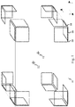
- Figure 1 shows one possible assembly of square shaped field generating coils around the measurement volume, in an embodiment of the present invention.
- the twenty-four coils 10 are arranged in groups of three coils in each of the eight corners of a rectangular frame 11.
- the three coils 10 in each corner are orthogonal to each other. If the measuring device is placed in a magnetically shielding room the frame 11 can be the inside wall of the room. Two possible locations for the origin, centers of the measuring volume, are indicated as 12.
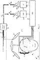
- FIG. 2 shows the electronics arrangement controlling the currents in the coil assembly 20 to provide either the measuring field and gradients for an MRI device, or the active compensation of the environmental interference of the MEG device, in an embodiment of the present invention.
- the measuring volume e.g. a MSR
- the setting up the system begins with determination of the field vectors B c for the coils 20 of the assembly in its environment.
- the data acquisition electronics 23 commands the current supply 29 having n c outputs 29' to feed current into the coils 20 in the assembly, each one at a time.
- the resulting coil signals are recorded by the magnetometer channel array 22' and stored in the acquisition system 23.
- these coil signals are decomposed into the Cartesian field components and their derivatives, which are the components of the B c -vectors for the MRI application.
- the M -matrix is formed from these B c -vectors, and the current vectors I MRI are determined by taking the inverse of M.
- Each one of these I MRI -vectors, when fed as input to the current supply 29, will result in a pure Cartesian measuring field or a pure gradient field.
- These vectors are stored in the MRI control unit 24.
- this unit controls the timing of the MRI sequence, and the recording field geometries by sending the proper I MRI -vectors - of both the uniform field and the gradient - via the link 26a to the n c -channel current supply 29.
- the n p first ones of these I AC vectors are multiplied by the error signals received from the sensors 22 used as zero detectors for the compensation feedback loops, and then transmitted via the link 26b through adders 27b and 27c and switch 28b to the current supply 29.
- the two switches 28a-b on the links 26a-b one can choose between the MRI 24 and MEG (active compensation) 25 functions.
- the adder unit 27a adds the two vectors I MRI that correspond to the MRI measuring field and the chosen gradient.
- the adder unit 27b adds the I AC -vectors (weighted by the n p error signals) to form an n c -component current vector that counteracts the dominant interference components (the n p PCA components of it). Both these signals are fed to the current supply 29 through the adder unit 27c, with the chosen mode switched on (28a or 28b).
- the MRI electronics 24 can function as a host device to the MEG measurement unit 23 which can be set as a slave device working as measuring instrument for the magnetic resonance signals. This is expressed in figure 2 as a two-way arrow between the two units 23, 24.
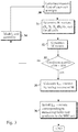
- Figure 3 shows an embodiment of the method according to the invention, as a flow chart of the process of designing coil assembly for the MRI application. This chart is kind of a summary of the steps already handled in the previous paragraphs.
- the magnetic field produced by each coil in the assembly is calculated or measured at origin 30.
- a field vector B c column vector comprising elements B x , B y , B z , dB x /dx, ...) for all the coils in the assembly 31.
- the matrix M 32 from the field vectors for all coils.
- the condition number of M 33 which tells how close to singular the matrix M actually is.
- condition number is more than a hundred (or any other desired threshold value)
- Figure 4 shows an example as a flow chart of the process of coil assembly design for another application, the active interference cancellation in MEG.
- the assembly of compensating coils 40 into the measuring volume, e.g. inside a MSR.
- the background interference 41 without any object present, and decompose this interfering field into components B 1 , B 2 , ..., B np (n p means the number of dominant PCA components of the interference).
- n p means the number of dominant PCA components of the interference.
- the magnetic fields originating from each coil at the origin 42 we can determine the field vectors B c (B 1 , B 2 , ..., B np , d 2 B x /dx 2 , ...) T for all the coils 43.
- the matrix M 44 When we have the B c 's, we can construct the matrix M 44. Similarly as in the embodiment of figure 3 , we can check the condition number of the matrix M 45, that is, check whether the matrix M is singular, close to singular or far from singular. We have to modify the assembly of coils 46 and remeasure the background interference until we achieve a matrix M which can be inverted (condition number less than 100, or any other desired threshold value). In that case we can calculate the current vectors I Ac 47 by using the equation (2). Finally, we can install the vectors I AC to the active compensation unit of the MEG device 48.
- the presented method can be implemented by a computer program which can control a data-processing device to execute the applicable method steps.
- the computer program can be stored in a medium applicable by the processor or other control means.
Landscapes
- Physics & Mathematics (AREA)
- Health & Medical Sciences (AREA)
- Life Sciences & Earth Sciences (AREA)
- General Physics & Mathematics (AREA)
- Engineering & Computer Science (AREA)
- Condensed Matter Physics & Semiconductors (AREA)
- Mathematical Physics (AREA)
- Nuclear Medicine, Radiotherapy & Molecular Imaging (AREA)
- Public Health (AREA)
- Animal Behavior & Ethology (AREA)
- Surgery (AREA)
- Molecular Biology (AREA)
- Medical Informatics (AREA)
- Heart & Thoracic Surgery (AREA)
- Biomedical Technology (AREA)
- Pathology (AREA)
- Biophysics (AREA)
- General Health & Medical Sciences (AREA)
- Veterinary Medicine (AREA)
- Pure & Applied Mathematics (AREA)
- Mathematical Optimization (AREA)
- Computational Mathematics (AREA)
- Mathematical Analysis (AREA)
- Theoretical Computer Science (AREA)
- Data Mining & Analysis (AREA)
- Radiology & Medical Imaging (AREA)
- Electromagnetism (AREA)
- Software Systems (AREA)
- Operations Research (AREA)
- Algebra (AREA)
- Databases & Information Systems (AREA)
- General Engineering & Computer Science (AREA)
- Magnetic Resonance Imaging Apparatus (AREA)
- High Energy & Nuclear Physics (AREA)
Description
- The invention relates to magnetic imaging technologies and specifically to creation of magnetic fields of specified, geometrically precise shape over a large volume in space.
- Magnetic fields of precise geometry are needed in medical magnetic imaging applications, like magnetic resonance imaging (MRI) and magnetoencephalography (MEG). Recently, also combination of the two imaging techniques has been proposed ("Microtesla MRI on the human brain combined with MEG", Vadim S. Zotev et al, Journ. Mag. Res. 194, pp 115-120, 2008).
- In patent
US 5661401 , an apparatus for generating a corrective magnetic field in a nuclear magnetic resonance (NMR) spectrometer has been disclosed. The electrical currents generating the field are calculated using matrix algebra. - In the MRI method the part of the human body that is studied is exposed to a uniform magnetic field, and to gradients of the field for decoding of the spatial information contained in the MRI signal. The geometry of the measuring field essentially contributes to the signal quality and geometric precision of the resulting MRI image. An ideal measuring field is free of field derivatives higher than first.
- In the MEG method the very weak magnetic signals resulting from the functioning of the human brain are recorded by sensors located around the head. One of the main problems in this technique is the protection of the measuring device against the environmental magnetic interference the strength of which may exceed the signals of interest by seven to eight orders of magnitude. This magnetic shielding problem can be solved by active compensation methods that counteract the interference using coil systems tailored to produce counter fields that very precisely match the geometry of the interference fields (see
WO2005/078467 ). - The interference fields in a typical MEG recording environment are relatively uniform and smooth. "Smooth" means here that the fields comprise of spatially uniform field components and only low order spatial derivatives of these components. Spatial derivatives higher than first order, say, are of very small amplitude in the interference. This is so because these fields arise from sources tens of meters away from the recording device, and are additionally smoothed by the magnetically shielding room (MSR) housing the MEG device. Therefore, the fields used to counteract these interference fields in an active compensation arrangement must also be smooth and tailored to optimally match the interference field geometry. This enables maximal compensation of the interference over relatively large volume of the size of the human head.
- In both MRI and MEG methods the coil systems must be located relatively close to the measuring device. This way the currents needed to create the measuring and counteracting fields stay reasonably small. Furthermore, if a feedback principle is used for the active compensation the compensation coils must necessarily be inside the MSR (
WO2005/078467 ). Placing the coils outside of the MSR would cause extra delay and lead to unstable feedback loop. - The requirements that the fields must be uniform or smooth over a large measuring volume, and must be generated by coils located near this volume, at a distance of one to two meters only, are contradictory. Field profiles generated by close-by coils necessarily contain second and higher derivatives, and the coils must be carefully designed to produce smooth fields and gradients over a volume as large as the size of human head, for example.
- A well-known, elementary example toward the solution of this kind of coil design problem are the so called Helmholz and Maxwell pairs: By properly choosing the distance between two circular, coaxial coils of same size one can create, mid between the two coils, an axial field Bx uniform up to the fourth derivative d4Bx /dx4. The coil assembly optimized this way is called a Helmholz-pair. The first non-zero derivative of its field is d4Bx /dx4. A spatially constant axial derivative dBx /dx smooth up to fifth derivative is created by a coil set called a Maxwell-pair where the first non-zero odd derivative beyond dBx /dx is d5Bx /dx5. But, to generate uniform magnetic fields in all three spatial directions (Bx,By,Bz), and their derivatives - constant over a macroscopic volume - one must design a coil assembly that simultaneously controls the magnetic fields in the three orthogonal directions, the five independent first derivatives of these components, and the seven independent second derivatives etc. This requirement formulates a kind of "generalized Helmholz/Maxwell coil design problem". Obviously, to solve this problem, a larger number of independent coils is needed than the two coils in the Helmholz and Maxwell cases.
- For practical applications this coil design problem is further complicated by the presence of magnetic materials in the vicinity of the coils, and specifically in MEG, by the presence of the MSR. Its walls contain material of high magnetic susceptibility which gets magnetized in the field produced by the current in the coils. This results in a considerable scattered field that is added to the direct field of the coils. The susceptibility values of the MSR wall elements and the characteristics of the joints between the elements vary from one MSR to another and may even change with time. Therefore designing the coil assembly by a mere calculation would require measurement and characterization of the room structure and magnetic properties of the wall elements in such a detailed manner that it is practically impossible.
- The objective of this invention is to present a method by which one can design a coil assembly that is able to produce uniform and smooth magnetic fields up to any desired order, even in the case that the immediate environment of the coil assembly contains magnetic materials.
- In the present invention the magnetic field geometry is controlled by properly selecting the nc currents, current vector I, fed into the nc coils of a geometrically fixed coil assembly. Each coil in the assembly is characterized by the field components and their gradients that it generates at a given point in space (origin). The key point of the invention is that by including in this characterization a "field-vector" B c for each coil and also field shapes (derivatives) which are wanted to be excluded from the generated fields, it is possible to formulate a simple algebraic method for calculating the current vectors I needed to 1) give the desired field components or derivatives of them and 2) keep those derivatives at zero which are wanted to be vanished at the origin. The field-vectors B c needed for the characterization of each coil can be calculated or measured. The latter approach is necessary in an environment containing magnetic materials.
- Described in more explicit manner, the present invention introduces a method of controlling the creation of a magnetic field with an assembly of coils, which field has a desired geometric shape around a given origin. The method is characterized in that it comprises the following steps:
- creating a test current in each coil at a time, measuring the magnetic field distribution around the origin caused by the test current and decomposing the measured magnetic fields into desired and undesired components of the magnetic field, wherein each coil in the assembly is characterized by the field components and their gradients that it generates at the origin, wherein the components of the magnetic field include field values and/or derivatives of desired order and wherein the undesired components contribute to magnetic field shapes which are wanted to be excluded from the generated magnetic field;
- forming a system of linear equations corresponding to the equation B = MI, where B is a field vector, I is a vector with components describing currents in the individual coils of said assembly of coils and M is a matrix describing the linear relationship between B and I, so that the system of linear equations is based on the decomposed components giving the same decomposition of the magnetic field that results from simultaneous powering of the coils of the coil assembly by a set of currents; and
- determining a set of currents that result in the desired geometric shape by solving the system of linear equations.
- In an embodiment of the present invention, the desired field components and the undesired field components are constructed from three orthogonal components of the magnetic field and their independent Cartesian derivatives.
- In an embodiment of the present invention, the desired field components are constructed from three orthogonal components of the magnetic field and their five independent Cartesian derivatives of the first order, and the undesired field components are seven independent Cartesian derivatives of the second order.
- In an embodiment of the present invention, the current vector is calculated by a product of a Moore-Penrose pseudo-inverse of a matrix comprising the field component vectors for each of the coils with the test current, and the summed field vector of the simultaneous powered coils at the origin.
- In an embodiment of the present invention, the method further comprises the following steps:
- determining a degree of singularity of the said matrix by a condition number, and in case the condition number of the said matrix exceeds a desired threshold value, thus indicating a singular or substantially singular matrix,
- modifying the coil assembly, and when the condition number of the said matrix is below the desired threshold value, thus indicating a non-singular matrix,
- calculating the set of currents.
- In an embodiment of the present invention, the desired field components comprise at least one dominant external interference component, or one or several linear combinations of the dominant external interference components, determined from a separate measurement of interference.
- In an embodiment of the present invention, the dominant external interference components used as desired field components are determined from a principal component analysis or an independent component analysis of the separate measurement of interference.
- In an embodiment of the present invention, the linear combinations of the dominant external interference components are used as feedback field shapes in an active compensation system, where the linear combinations forming the feedback field shapes, and the locations and orientations of the sensors, are chosen so that the coupling between simultaneously operating feedback loops is minimized.
- In an embodiment of the present invention, the method further comprises switching between the magnetic resonance imaging functionality creating the magnetic fields with gradients, and the magnetoencephalography device functionality performing active compensation for the environmental interference.
- According to a second aspect of the present invention, the inventive idea also comprises a magnetic resonance imaging or magnetoencephalography apparatus in accordance with claim 6.
- In an embodiment of the present invention, the control means is configured to construct the desired field components and the undesired field components from three orthogonal components of the magnetic field and their independent Cartesian derivatives.
- In an embodiment of the present invention, the control means is configured to construct the desired field components from three orthogonal components of the magnetic field and their five independent Cartesian derivatives of the first order, and the undesired field components are seven independent Cartesian derivatives of the second order.
- In an embodiment of the present invention, the control means is configured to calculate the current vector by a product of a Moore-Penrose pseudo-inverse of a matrix comprising the field component vectors for each of the coils with the test current, and the summed field vector of the simultaneous powered coils at the origin.
- In an embodiment of the present invention, the apparatus further comprises:
- the control means configured to determine a degree of singularity of the said matrix by a condition number, and in case the condition number of the said matrix exceeds a desired threshold value, thus indicating a singular or substantially singular matrix,
- modifying means is configured to modify the coil assembly, and when the condition number of the said matrix is below the desired threshold value, thus indicating a non-singular matrix,
- the control means is configured to calculate the set of currents.
- In an embodiment of the present invention, the desired field components comprise at least one dominant external interference component, or one or several linear combinations of the dominant external interference components, determined from a separate measurement of interference.
- In an embodiment of the present invention, the control means is configured to determine the dominant external interference components used as desired field components from a principal component analysis or an independent component analysis of the separate measurement of interference.
- In an embodiment of the present invention, the control means is configured to use the linear combinations of the dominant external interference components as feedback field shapes in an active compensation system, where the linear combinations forming the feedback field shapes, and the locations and orientations of the sensors, are chosen so that the coupling between simultaneously operating feedback loops is minimized.
- In an embodiment of the present invention, the apparatus further comprises switching means in order to choose between the magnetic resonance imaging functionality configured to create the magnetic fields with gradients, and the magnetoencephalography device functionality configured to perform active compensation for the environmental interference.
- According to a third aspect of the invention, the inventive idea further comprises a computer program in accordance with
claim 11. - The advantages of the present invention are that with the presented coil assembly design method we can produce desired and accurate magnetic fields with the assembly which is able to effectively compensate different kinds of active interference situations over a relatively large volume. A further advantage is that this design method is mainly implemented with matrix algebra, and therefore the application of the invention can be performed in a straight-forward manner in the existing control logic or processor of the MEG device, for instance. A further advantage is that the measuring volume to be compensated is large, and finally, the method is even applicable inside the magnetically shielding rooms which typically include magnetic materials, previously interfering the active compensation systems significantly.
-
-
Figure 1 discloses an example of an assembly of square shaped field generating coils around a measurement volume, -
figure 2 discloses an embodiment of the electronics arrangement controlling the currents in the coil assembly to either provide the measuring field and gradients for the MRI device or the active compensation of the environmental interference of the MEG device, -
figure 3 discloses an embodiment of the method as a flow chart of the process of the coil assembly design for the MRI application, and -
figure 4 discloses an embodiment of the method as a flow chart of the process of the coil assembly design for the active interference cancellation in MEG. - Reference will now be made in detail to the embodiments of the present invention.
- The present invention formulates a method for solving the "generalized Helmholz/Maxwell design problem" described in the background section. The method can be extended in a straightforward manner beyond the Helmholz and Maxwell design problems, that is, for designing coil assemblies that create magnetic fields with vanishing derivatives up to any required order. For simplicity, the derivatives are cut to second order in the examples below. However, in a situation where the coils are located close to the measured object and where very smooth and homogenous magnetic fields are desired, we might use derivatives of even higher order than two. The orders of the derivatives taken into the calculations can be chosen according to the accuracy requirements in the used application. Of course, the greater amount of the derivatives taken into account increases the complexity of the calculations (the dimensions of the vectors and matrices), but the main principle of the algebraic operations remain the same.
- Three different conditions in which the method can be applied, for instance, are described in the following. The design conditions are presented in the order of increasing complexity.
- First we describe the first condition where the method according to the invention can be applied.
- In this simplest case the coil assembly is located in an environment that contains no magnetic materials, and the goal is to generate, at a given point inside the coil assembly (the origin), strictly uniform fields in the three Cartesian directions (Bx, By, Bz), and constant first derivatives of these three components.
- In a volume that is free of magnetic sources (magnetic materials or electric currents) the divergence and curl of magnetic field are zero. Therefore, out of the nine possible first derivatives (dBx/dx, dBx/dy, dBx/dz, dBy/dx, dBy/dy, dBy/dz, dBz/dx, dBz/dy, dBz/dz) only five are independent, for example dBx/dx, dBx/dy, dBx/dz, dBy/dy, and dBy/dz. Similarly, for a divergence and curl free vector field in three dimensional space, out of the 27 second derivatives only seven are independent, for example d2Bx/dx2, d2Bx/dxdy, d2Bx/dxdz, d2By/dxdy, d2Bx/dx2, d2By/dy2, d2By/dydz and d2Bx/dydz.
- A set of nc coils is specified and the three magnetic field components, the five first derivatives, and the seven second derivatives of the fields arising from the current running in each one of the coils are calculated at the origin. In an environment free of magnetic materials this can be done by using simple, well known mathematical expressions. In this way for each of the nc coils a field-vector, B c , is obtained with fifteen components, which are Bx, By, Bz, dBx/dx, dBx/dy, dBx/dz, dBy/dy, dBy/dz, d2Bx/dx2, d2Bx/dxdy, d2Bx/dxdz, d2By/dxdy, d2Bx/dx2, d2By/dy2, d2By/dydz, and d2Bx/dydz.
- Using these nc field-vectors as column vectors, a 15 x nc matrix M is formed. If the nc coils are simultaneously powered with currents I1, I2, ..., Inc, the resulting field vector for the whole assembly, at the origin, is given by the matrix equation


- Here inv(M) is inverse matrix of M if the number of coils is the same as the number of components in the field vector B, 15 in this example. If the number of coils is smaller or larger than the number of components in the field vector, then inv(M) is the Moore-Penrose pseudo-inverse of M.
- For example, the currents needed in the coils of the assembly to create a uniform field of one Tesla in the x-direction, Bx, are obtained from equation (2) by using the column vector B = [1, 0, 0, ..., 0]. The field generated by the resulting I-vector is in the x-direction, that is By, Bz = 0. In addition, all of its first and second order derivatives are zero at the origin. It should be noted that the field derivatives up to second order vanish in the origin only because they are included the model (B c -vector) for each coil. Derivatives left out from the B c -vectors are not controlled in the algorithm defined by equations (1) and (2).
- The only design problem left after equation (2) is that the overall geometry of the coil assembly must be so chosen that the matrix M is not singular, and thus inv(M) exists. This is not difficult because M is strictly singular only for highly symmetric assemblies. From practical point of view it also matters how close to singular M is. If M is close to singular, creation of some field components or their derivatives may require very high currents in some of the coils. Therefore, the condition number of matrix M, which is a measure of how close to singular M is, is a good measure of the quality of geometric design of the coil assembly also. In case we have a coil assembly located e.g. on a single plane or in otherwise symmetrical mutual locations, it usually occurs that at least one of the resulting currents in the compensating coil assembly needs to be notably high in order to work properly. This is not feasible or economical. Therefore, a good measure for indicating this kind of behaviour is the condition number which in that uneconomical case would be big (e.g. over 100). In order to minimize the condition number, we must relocate the coil assembly e.g. in a less symmetrical fashion, and then we will achieve an optimal coil assembly where with relatively small currents it is possible to accomplish a well-functioning system for creation of smooth measuring field in MRI or effective active compensation in MEG.
- The cases where the number of coils in the assembly is 1) equal to, 2) larger than, or 3) smaller than the number of components in the field vector B differ in principle from each other.
- Case 1) is the simplest. Here the number of coils (available "degrees of freedom") is the same as the number of quantities to control (the three field components and their 5+7 independent derivatives at the origin). In this case M is a 15x15 square matrix and equation (2) has a unique solution. The current vector I needed to create a uniform field in the z-direction, Bz, for example, is obtained from equation (2) by using the column vector B = [0, 0, 1, 0, ... , 0]. The resulting field is precisely (with numerical accuracy) along the z-axis and all its derivatives up to the second derivatives vanish at the origin.
- In case 2) the system defined by equation (1) is underdetermined. The number of coils is larger than the number of quantities to be controlled. In this case equation (1) has an infinite number of solutions I. The solution given by the Moore-Penrose pseudo-inverse is the one that has the smallest Euclidian norm, that is, the smallest length of the vector I. In this case another optimal solution I can also be chosen: the shortest vector I among those solutions that have nonzero currents only in 15 of the nc coils. This is a way to find out which ones of the nc coils are least useful for creation of the uniform fields and constant first derivatives, and could possibly be left out from the assembly. This latter solution usually requires higher maximal currents than the Moore-Penrose pseudo-inverse solution.
- In the overdetermined case 3) an exact solution I for equation (1) does not exist. Here the number of the available degrees of freedom (number of coils) is smaller than the number of quantities to be controlled. In this case the Moore-Penrose pseudo-inverse gives a vector I that is optimal in the sense that it minimizes the Euclidian norm of the deviation I-MB. This current vector I is a least squares solution to the overdetermined problem.
- The number of components in vector B, and in all the B c's can be increased to include derivative orders higher than two. This may be needed if uniform fields and precise first gradients are needed over a relatively large volume, like in the MRI application. Or this may be needed in the active shielding application if the interference contains components expressing complicated geometry, that is, higher derivatives. To achieve a satisfactory result in this case the number of coils in the assembly must also be increased.
- A second condition where the method according to the invention can be applied, is described in the following.
- In reality the coil assembly will be installed in a building environment that has magnetic materials and structures. Specifically, in the case of MEG, the magnetically shielding room with its high permeability walls will be quite close to the coils, resulting in a considerable scattered field. The geometry and magnetic properties of these materials are usually complicated and impossible to characterize in detail. Therefore, obtaining the B c vectors for each coil by calculation may be inaccurate or impossible. In this case, the assembly of coils must be made and installed first, and then the field vectors B c must be measured one at a time by feeding current into each coil in the assembly. For example, in the case of MEG - and in devices possibly combining MEG and MRI in the same instrument - measuring the field and its derivatives is straightforward because the MEG device itself contains an array of a large number of magnetic sensors. From the response, a signal vector, of the MEG sensor array to the current excitation fed into each one of the coils, the field components and their derivatives needed for B c are easily derived. If an MEG sensor array is not available, the measurement of the field and its derivatives can be made with some other accurately calibrated sensor array, or with one sensor that can be accurately moved around the origin.
- After the B c -vectors for each coil have been determined by measurement, the procedure for obtaining the I-vectors corresponding to the different components of B is applied exactly as in the first condition above.
- A third condition where the method according to the invention can be applied, is described in the following.
- This third case applies to the MEG application of the present method. The goal in the MRI application is to use the coils to get uniform field components and constant gradients (first derivatives) over the measurement volume, whereas in the MEG application the goal is to be able to counteract the environmental magnetic interference as precisely as possible. This is not necessarily optimally done by cancelling the uniform fields and the spatially constant first derivatives only, because the dominant interference field shapes inside an MSR may contain higher derivatives. Therefore, to achieve optimal cancellation one must determine the current distributions I that accurately reproduce the actual dominant interference field patterns, but exclude the unwanted higher derivative field shapes.
- The actual dominant interference patterns can be determined by recording the interference signal with the MEG system (no subject in the helmet) and making for example a principal component analysis (PCA) on the multichannel MEG signal. Another embodiment is to make an independent component analysis (ICA) on the multichannel MEG signal. After this the present method can be applied so that the first np components of the B c -vectors are the projections of the coil signal along the dominant np principal components of the previously recorded interference. To prevent the appearance of the unwanted higher derivatives in the cancellation fields, the rest of the components in the B c -vectors are chosen among these higher derivatives.
- In principle, in the third condition exactly the same procedure is applied as in the second condition. In the B c -vectors the first few components (Bx, By, Bz, ...) are only replaced by the dominant PCA components of the actual, measured interference.
- In the active compensation application in MEG the interference cancellation runs as a feedback system. Magnetometer sensors on different sides of the MEG helmet are used as zero detectors in feedback loops that control the currents in the compensating coil assembly (
WO2005/078467 A1 ). Several of such feedback loops run in parallel to compensate for the np dominant PCA components of the environmental interference. It is advantageous for the stable functioning of such a system of parallel feedback loops to maximally decouple the loops from each other. The coil combination driven by one loop should create a minimal signal in the zero detectors of the other loops. This prevents the counteractions from circulating among the different control loops and therefore makes the entire control system faster and stable over a wider bandwidth. - This orthogonalization of the control system is built in the first and second conditions above. This is because in these conditions the controlled field shapes are orthogonal Cartesian components; it is natural to choose the zero detector sensor for the Bx - feedback loop strictly in x-direction so that it does not see the By and Bz components etc.
- This, however, is not automatically the case if the third condition is used to achieve maximal interference compensation. The np dominant PCA-components are not "pure" magnetic field components precisely orthogonal in space. Even if the first three of them are nearly uniform fields and define "principal interference directions" in three dimensions, these directions are often rotated with respect to the principal directions of the measuring device and the coil assembly. In this case the parallel feedback loops can be optimally decoupled by mixing the dominant np PCA components of the interference with a proper linear transformation within the signal sub-space defined by these PCA components. The optimal linear transformation is constructed so that it rotates the coordinate system defined by the PCA components along the principal axes of the device and mixes the interference field shapes so that the zero detector of any feedback loop does not see the counteraction fields related to the other control loops.
- To construct the mathematical formalism, let us first denote the nch x np and nch x nc dimensional PCA and coil signal subspaces by matrices P and C, respectively. Here nch is the number of measurement channels. Also, let us denote the actual signal vector containing measurement values from all channels by f. Now, the task is to produce a counteracting signal as precise to f as possible, given the set of coil signals C.
- Mathematically, this can be formulated as


- Here pinv (P 0) denotes pseudo inverse of P 0. By setting f = Px and solving for K in such a way that (3) holds true as accurately as possible, we have

- This is the optimal coil mixing matrix. As a final step, we can remove the cross-talk between the zero detectors by rotating the matrix K. First, set C 2 = CK. The rotation K orth = KR will be done so that in the rotated set C 3 = C 2 R = CKR the zero detectors will be orthogonal, i.e., C 20 R = I is a nz x nz dimensional identity matrix, where nz is the number of zero detectors and C 20 only contains the contribution of the zero detectors. Thus, we have R = pinv(C 20) and the rotated mixing matrix is

- By utilizing an embodiment according to the method of the present invention, one and the same coil assembly can be used for MRI field and gradient generation, and for MEG active cancellation of interference in a combined MEG/MRI instrument. In these cases and in one embodiment of the invention, the MRI electronics controlling magnetic resonance imaging measurement fields can function as a host device. In that case the MEG device can act as a slave device for the MRI electronics, the MEG device being the measuring instrument for the magnetic resonance signal.
- The same coil system can also be used for different measurement locations (origins) within the coil assembly, like seated and supine measurement positions in MEG. The vectors B c for each coil in the assembly only need to be determined for each measurement location separately, either by calculation or measurement. The same applies to the environmental interference field PCA analysis in the third condition. After this the current distributions I for each of the measurement locations will be obtained from equation (2). Because the B c-vectors and thus the M-matrices are different for the two measurement positions, the resulting I-vectors will also differ. But there is no need to use different coil assemblies, or move or geometrically change the coil assembly when changing from one measurement position to the other. Also, possible repositioning of the measuring device with respect to the coil assembly only requires determination of a new M-matrix, and then calculation of new current vectors I using equation (2).
- Reference is now made to the additional examples, which are illustrated in the accompanying drawings.
-
Figure 1 shows one possible assembly of square shaped field generating coils around the measurement volume, in an embodiment of the present invention. The twenty-fourcoils 10 are arranged in groups of three coils in each of the eight corners of arectangular frame 11. The three coils 10 in each corner are orthogonal to each other. If the measuring device is placed in a magnetically shielding room theframe 11 can be the inside wall of the room. Two possible locations for the origin, centers of the measuring volume, are indicated as 12. -
Figure 2 shows the electronics arrangement controlling the currents in thecoil assembly 20 to provide either the measuring field and gradients for an MRI device, or the active compensation of the environmental interference of the MEG device, in an embodiment of the present invention. The measuring volume (e.g. a MSR) is depicted as 21 where the patient is located in the vicinity of the measuringsensors 22. The setting up the system begins with determination of the field vectors B c for thecoils 20 of the assembly in its environment. Thedata acquisition electronics 23 commands thecurrent supply 29 having nc outputs 29' to feed current into thecoils 20 in the assembly, each one at a time. The resulting coil signals are recorded by the magnetometer channel array 22' and stored in theacquisition system 23. - For setting up the MRI-
function 24, these coil signals are decomposed into the Cartesian field components and their derivatives, which are the components of the B c -vectors for the MRI application. After this the M-matrix is formed from these B c -vectors, and the current vectors I MRI are determined by taking the inverse of M. Each one of these I MRI -vectors, when fed as input to thecurrent supply 29, will result in a pure Cartesian measuring field or a pure gradient field. These vectors are stored in theMRI control unit 24. In the MRI function this unit controls the timing of the MRI sequence, and the recording field geometries by sending the proper I MRI -vectors - of both the uniform field and the gradient - via thelink 26a to the nc-channelcurrent supply 29. - If the active interference compensation function is operated following the second condition above then these I MRI current vectors can be used for active compensation as well. But if the third condition is applied, then information from the PCA analysis of the interference must be used for defining the B c -vectors. The recorded coil signals are now decomposed in a coordinate system comprising of the first np PCA components of the interference and then higher derivatives of the B-field components (see also
Fig. 4 ). This leads to B c-vectors and M-matrix slightly different from the MRI case, and to current vectors I AC that differ from the vectors I MRI. Whenactive compensation 25 is on, the np first ones of these I AC vectors are multiplied by the error signals received from thesensors 22 used as zero detectors for the compensation feedback loops, and then transmitted via thelink 26b throughadders switch 28b to thecurrent supply 29. By the twoswitches 28a-b on thelinks 26a-b one can choose between theMRI 24 and MEG (active compensation) 25 functions. In the MRI mode, theadder unit 27a adds the two vectors I MRI that correspond to the MRI measuring field and the chosen gradient. Whereas, in the MEG mode during active compensation, theadder unit 27b adds the I AC-vectors (weighted by the np error signals) to form an nc-component current vector that counteracts the dominant interference components (the np PCA components of it). Both these signals are fed to thecurrent supply 29 through theadder unit 27c, with the chosen mode switched on (28a or 28b). In one embodiment, as disclosed earlier regarding the MRI measurements, theMRI electronics 24 can function as a host device to theMEG measurement unit 23 which can be set as a slave device working as measuring instrument for the magnetic resonance signals. This is expressed infigure 2 as a two-way arrow between the twounits -
Figure 3 shows an embodiment of the method according to the invention, as a flow chart of the process of designing coil assembly for the MRI application. This chart is kind of a summary of the steps already handled in the previous paragraphs. In the first step in the procedure, the magnetic field produced by each coil in the assembly is calculated or measured atorigin 30. After this we determine a field vector B c (column vector comprising elements Bx, By, Bz, dBx/dx, ...) for all the coils in theassembly 31. Then we are ready to construct thematrix M 32 from the field vectors for all coils. After this we can determine the condition number ofM 33, which tells how close to singular the matrix M actually is. If the condition number is more than a hundred (or any other desired threshold value), we have to modify thecoil assembly 34. Depending on the situation, this means relocating or reorienting the individual coils, or decreasing or increasing the number of coils in the assembly. In that case, we have to start from the beginning of the procedure, and calculate or measure the fields for each coil of the modified assembly again 30. - When we result in the condition number less than a hundred, we may decide that the coil assembly is feasible, and we may calculate 35 the current vectors I MRI according to equation (2). Finally, in the
last step 36, we can install the I MRI-vectors in the MRI unit which correspond to the measuring fields and gradients. -
Figure 4 shows an example as a flow chart of the process of coil assembly design for another application, the active interference cancellation in MEG. At first, we set up the assembly of compensatingcoils 40 into the measuring volume, e.g. inside a MSR. Then we can measure thebackground interference 41 without any object present, and decompose this interfering field into components B1, B2, ..., Bnp (np means the number of dominant PCA components of the interference). After this we may measure the magnetic fields originating from each coil at theorigin 42. Then we can determine the field vectors B c (B1, B2, ..., Bnp, d2Bx/dx2, ...)T for all thecoils 43. When we have the B c's, we can construct thematrix M 44. Similarly as in the embodiment offigure 3 , we can check the condition number of thematrix M 45, that is, check whether the matrix M is singular, close to singular or far from singular. We have to modify the assembly ofcoils 46 and remeasure the background interference until we achieve a matrix M which can be inverted (condition number less than 100, or any other desired threshold value). In that case we can calculate the current vectors I Ac 47 by using the equation (2). Finally, we can install the vectors I AC to the active compensation unit of the MEG device 48. - The presented method can be implemented by a computer program which can control a data-processing device to execute the applicable method steps. The computer program can be stored in a medium applicable by the processor or other control means.
- It is obvious to a person skilled in the art that with the advancement of technology, the basic idea of the invention may be implemented in various ways. Thus, the invention and its embodiments are not limited to the examples described above; instead, they may vary within the scope of the claims.
Claims (11)
- A method of controlling the creation of a magnetic field with an assembly of coils, which field has a desired geometric shape around a given origin, characterized in that the method comprises the following steps:creating a test current in each coil at a time, measuring the magnetic field distribution around the origin caused by the test current and decomposing the measured magnetic fields into desired and undesired components of the magnetic field, wherein each coil in the assembly is characterized by the field components and their gradients that it generates at the origin, wherein the components of the magnetic field include field values and/or derivatives of desired order and wherein the undesired components contribute to magnetic field shapes which are wanted to be excluded from the generated magnetic field;forming a system of linear equations corresponding to the equation B = MI, where B is a field vector, I is a vector with components describing currents in the individual coils of said assembly of coils and M is a matrix describing the linear relationship between B and I, so that the system of linear equations is based on the decomposed components giving the same decomposition of the magnetic field that results from simultaneous powering of the coils of the coil assembly by a set of currents; anddetermining a set of currents that result in the desired geometric shape by solving the system of linear equations.
- A method according to claim 1, characterized in that the desired field components are constructed from three orthogonal components of the magnetic field and their five independent Cartesian derivatives of the first order, and the undesired field components are seven independent Cartesian derivatives of the second order.
- A method according to any of the preceding claims, characterized in that the current vector is calculated by a product of a Moore-Penrose pseudo-inverse of a matrix comprising the field component vectors for each of the coils with the test current, and the summed field vector of the simultaneous powered coils at the origin.
- A method according to claim 3, characterized in that the method further comprises the following steps:determining a degree of singularity of the said matrix by a condition number, and in case the condition number of the said matrix exceeds a desired threshold value, thus indicating a singular or substantially singular matrix,modifying the coil assembly by relocating or reorienting the individual coils, or decreasing or increasing the number of coils in the assembly, and when the condition number of the said matrix is below the desired threshold value, thus indicating a non-singular matrix,calculating the set of currents.
- A method according to any of the preceding claims, characterized in that the desired field components comprise at least one dominant external interference component, or one or several linear combinations of the dominant external interference components, determined from a separate measurement of interference.
- A magnetic resonance imaging or magnetoencephalography apparatus with a coil assembly (20) for creation of a magnetic field that has a desired geometric shape around a given origin, comprising:a sensor array (22') comprising a plurality of magnetometer sensors (22) for measuring multi-channel data, andcontrol means (23) for controlling the apparatus,
characterized in that the control means (23) is configured to create a test current (29') in each coil (20) at a time, to measure the magnetic field distribution around the origin caused by the test current (29') and to decompose the measured magnetic fields into desired and undesired components of the magnetic field, wherein each coil in the coil assembly (20) is characterized by the field components and their gradients that it generates at the origin, wherein the components of the magnetic field include field values and/or derivatives of desired order and wherein the undesired components contribute to magnetic field shapes which are wanted to be excluded from the generated magnetic field;the control means (23) is configured to form a system of linear equations corresponding to the equation B = MI, where B is a field vector, I is a vector with components describing currents in the individual coils of the coil assembly (20) and M is a matrix describing the linear relationship between B and I, so that the system of linear equations is based on the decomposed components giving the same decomposition of the magnetic field that results from simultaneous powering of the coils (20) of the coil assembly by a set of currents; andthe control means (23) is configured to determine a set of currents that result in the desired geometric shape by solving the system of linear equations. - An apparatus according to claim 6, characterized in that the control means (23) is configured to construct the desired field components from three orthogonal components of the magnetic field and their five independent Cartesian derivatives of the first order, and the undesired field components are seven independent Cartesian derivatives of the second order.
- An apparatus according to any of the claims 6-7, characterized in that the control means (23) is configured to calculate the current vector by a product of a Moore-Penrose pseudo-inverse of a matrix comprising the field component vectors for each of the coils (20) with the test current (29'), and the summed field vector of the simultaneous powered coils (20) at the origin.
- An apparatus according to claim 8, characterized in that the apparatus further comprises:the control means (23) configured to determine a degree of singularity of the said matrix by a condition number, and in case the condition number of the said matrix exceeds a desired threshold value, thus indicating a singular or substantially singular matrix,modifying means is configured to modify the coil assembly (20) by relocating or reorienting the individual coils, or decreasing or increasing the number of coils in the assembly, and when the condition number of the said matrix is below the desired threshold value, thus indicating a non-singular matrix,the control means (23) is configured to calculate the set of currents.
- An apparatus according to any of the claims 6-9, characterized in that the desired field components comprise at least one dominant external interference component, or one or several linear combinations of the dominant external interference components, determined from a separate measurement of interference, and in that the control means (23) is configured to use the linear combinations of the dominant external interference components as feedback field shapes in an active compensation system (25, 29, 20), where the linear combinations forming the feedback field shapes, and the locations and orientations of the magnetometer sensors (22), are chosen so that the coupling between simultaneously operating feedback loops is minimized.
- A computer program for controlling a creation of a magnetic field with a coil assembly which field has a desired geometric shape around a given origin, characterized in that the computer program comprises code adapted to perform the following steps when executed on a data-processing device:facilitating creating of a test current in each coil at a time, facilitating measuring the magnetic field distribution around the origin caused by the test current and decomposing the measured magnetic fields into desired and undesired components of the field, wherein each coil in the coil assembly is characterized by the field components and their gradients that it generates at the origin, wherein the components of the magnetic field include field values and/or derivatives of desired order and wherein the undesired components contribute to magnetic field shapes which are wanted to be excluded from the generated magnetic field;forming a system of linear equations corresponding to the equation B = MI, where B is a field vector, I is a vector with components describing currents in the individual coils of the coil assembly and M is a matrix describing the linear relationship between B and I, so that the system of linear equations is based on the decomposed components giving the same decomposition of the magnetic field that results from simultaneous powering of the coils of the coil assembly by a set of currents; and
determining a set of currents that result in the desired geometric shape by solving the system of linear equations.
Applications Claiming Priority (2)
| Application Number | Priority Date | Filing Date | Title |
|---|---|---|---|
| FI20105313A FI124019B (en) | 2010-03-26 | 2010-03-26 | Method of designing coil systems to form magnetic fields of desired geometry |
| PCT/FI2011/050249 WO2011117471A1 (en) | 2010-03-26 | 2011-03-24 | Method for designing coil systems for generation of magnetic fields of desired geometry, a magnetic resonance imaging or magnetoencephalography apparatus with a coil assembly and a computer program |
Publications (3)
| Publication Number | Publication Date |
|---|---|
| EP2561375A1 EP2561375A1 (en) | 2013-02-27 |
| EP2561375A4 EP2561375A4 (en) | 2016-07-27 |
| EP2561375B1 true EP2561375B1 (en) | 2020-01-01 |
Family
ID=42074418
Family Applications (1)
| Application Number | Title | Priority Date | Filing Date |
|---|---|---|---|
| EP11758880.6A Active EP2561375B1 (en) | 2010-03-26 | 2011-03-24 | Method for designing coil systems for generation of magnetic fields of desired geometry, a magnetic resonance imaging or magnetoencephalography apparatus with a coil assembly and a computer program |
Country Status (6)
| Country | Link |
|---|---|
| US (1) | US9977764B2 (en) |
| EP (1) | EP2561375B1 (en) |
| JP (1) | JP5792791B2 (en) |
| CA (1) | CA2794126C (en) |
| FI (1) | FI124019B (en) |
| WO (1) | WO2011117471A1 (en) |
Families Citing this family (16)
| Publication number | Priority date | Publication date | Assignee | Title |
|---|---|---|---|---|
| DE102016202240A1 (en) * | 2016-02-15 | 2017-08-17 | Siemens Healthcare Gmbh | MAGNETIC IMAGING |
| JP2017191040A (en) * | 2016-04-14 | 2017-10-19 | セイコーエプソン株式会社 | Magnetic field measuring apparatus and magnetic field measuring method |
| JP2017191039A (en) * | 2016-04-14 | 2017-10-19 | セイコーエプソン株式会社 | Magnetic field measuring apparatus and magnetic field measuring apparatus calibration method |
| JP6996135B2 (en) | 2017-07-03 | 2022-01-17 | 株式会社リコー | Information processing equipment, information processing methods, and programs |
| US11255932B2 (en) | 2018-12-10 | 2022-02-22 | Electronics And Telecommunications Research Institute | Magnetic-field-generating coil system, imaging system having magnetic-field-generating coil system, and method for operating imaging system |
| US11980466B2 (en) * | 2020-02-12 | 2024-05-14 | Hi Llc | Nested and parallel feedback control loops for ultra-fine measurements of magnetic fields from the brain using a neural detection system |
| WO2021242680A1 (en) * | 2020-05-28 | 2021-12-02 | Hi Llc | Systems and methods for recording neural activity |
| JP7370008B2 (en) | 2020-06-16 | 2023-10-27 | 浜松ホトニクス株式会社 | Brain measurement device and brain measurement method |
| JP7370009B2 (en) * | 2020-06-16 | 2023-10-27 | 浜松ホトニクス株式会社 | Brain measurement device and brain measurement method |
| EP4115194A2 (en) * | 2021-05-14 | 2023-01-11 | Magnetic Shields Limited | A magnetic shield |
| JP7644930B2 (en) * | 2021-06-04 | 2025-03-13 | 浜松ホトニクス株式会社 | Brain measuring device and brain measuring method |
| EP4352526A1 (en) * | 2021-06-09 | 2024-04-17 | Fieldline Inc. | Modular magnetic field compensation coil array |
| CN115843336A (en) * | 2021-06-30 | 2023-03-24 | 磁盾有限公司 | Magnetic shield |
| JP7742073B2 (en) * | 2021-08-30 | 2025-09-19 | 浜松ホトニクス株式会社 | Brain measurement device and brain measurement method |
| WO2023078564A1 (en) * | 2021-11-05 | 2023-05-11 | Shimadzu Corporation | Improvements in and relating to magnetic field nulling |
| CN115932677A (en) * | 2022-12-22 | 2023-04-07 | 中科知影(北京)科技有限公司 | Local magnetic field compensation device, magnetic field compensation system and method |
Family Cites Families (17)
| Publication number | Priority date | Publication date | Assignee | Title |
|---|---|---|---|---|
| US5289151A (en) * | 1987-12-11 | 1994-02-22 | British Technology Group Limited | Electrical coils |
| US5594849A (en) * | 1991-08-09 | 1997-01-14 | Yale University | Biomedical magnetism imaging apparatus and method |
| US5661401A (en) | 1995-03-13 | 1997-08-26 | Jeol Ltd. | Apparatus for generating corrective magnetic field |
| US5689189A (en) * | 1996-04-26 | 1997-11-18 | Picker International, Inc. | Technique for designing distributed radio frequency coils and distributed radio frequency coils designed thereby |
| US6078177A (en) | 1998-01-05 | 2000-06-20 | Picker International, Inc. | Flared gradient coil set with a finite shield current |
| JP2000037362A (en) | 1998-07-21 | 2000-02-08 | Toshiba Corp | Environmental noise magnetic field elimination device |
| JP2000342552A (en) * | 1999-06-08 | 2000-12-12 | Hitachi Medical Corp | Method for correcting unequalness of static magnetic field in magnetic resonance imaging system |
| GB2407388A (en) | 2000-09-11 | 2005-04-27 | Nmr Holdings No 2 Pty Ltd | Method of designing asymmetric radio frequency coils for magnetic resonance |
| US6947877B2 (en) | 2000-12-07 | 2005-09-20 | New York University | Methods for optimizing magnetic resonance imaging systems |
| FI118577B (en) | 2004-02-13 | 2007-12-31 | Elekta Ab | Procedure for protecting measuring device against interference |
| JP4829231B2 (en) * | 2004-06-10 | 2011-12-07 | ユニリーバー・ナームローゼ・ベンノートシヤープ | Apparatus and method for reducing interference |
| JP4365275B2 (en) | 2004-06-28 | 2009-11-18 | 株式会社日立製作所 | Uniform magnetic field generator |
| US7362101B2 (en) * | 2005-04-27 | 2008-04-22 | The Regents Of The University Of California | Sense optimized MRI RF coil designed with a target field method |
| FI119133B (en) * | 2005-04-28 | 2008-07-31 | Elekta Ab | Method and apparatus for eliminating interference during electromagnetic multichannel measurement |
| WO2007113992A1 (en) * | 2006-03-31 | 2007-10-11 | Hitachi Medical Corporation | Magnetic resonance imaging device and method |
| JP5266597B2 (en) * | 2008-06-17 | 2013-08-21 | 株式会社国際電気通信基礎技術研究所 | Brain activity information output device, brain activity information output method |
| CN104459584B (en) * | 2009-12-02 | 2018-03-20 | 纳纳利塞斯公司 | Method and apparatus for producing uniform magnetic field |
-
2010
- 2010-03-26 FI FI20105313A patent/FI124019B/en active IP Right Grant
-
2011
- 2011-03-24 JP JP2013500548A patent/JP5792791B2/en active Active
- 2011-03-24 WO PCT/FI2011/050249 patent/WO2011117471A1/en not_active Ceased
- 2011-03-24 CA CA2794126A patent/CA2794126C/en active Active
- 2011-03-24 US US13/637,650 patent/US9977764B2/en active Active
- 2011-03-24 EP EP11758880.6A patent/EP2561375B1/en active Active
Non-Patent Citations (1)
| Title |
|---|
| None * |
Also Published As
| Publication number | Publication date |
|---|---|
| JP2013523201A (en) | 2013-06-17 |
| WO2011117471A1 (en) | 2011-09-29 |
| CA2794126C (en) | 2019-07-02 |
| EP2561375A1 (en) | 2013-02-27 |
| FI20105313A7 (en) | 2011-09-27 |
| EP2561375A4 (en) | 2016-07-27 |
| FI124019B (en) | 2014-02-14 |
| CA2794126A1 (en) | 2011-09-29 |
| FI20105313A0 (en) | 2010-03-26 |
| JP5792791B2 (en) | 2015-10-14 |
| US9977764B2 (en) | 2018-05-22 |
| US20130197838A1 (en) | 2013-08-01 |
Similar Documents
| Publication | Publication Date | Title |
|---|---|---|
| US9977764B2 (en) | Method for designing coil systems for generation of magnetic fields of desired geometry, a magnetic resonance imaging or magnetoencephalography apparatus with a coil assembly and a computer program | |
| Holmes et al. | Balanced, bi-planar magnetic field and field gradient coils for field compensation in wearable magnetoencephalography | |
| EP2591375B1 (en) | Method for adjusting interference signal space in bio-magnetic field measurements | |
| JP6253592B2 (en) | Active resistive shimming for MRI equipment | |
| JP2022515825A (en) | Hysteresis correction in magnetic resonance imaging | |
| CA2518674C (en) | Method and system for processing a multi-channel measurement of magnetic fields | |
| AU2014277683B2 (en) | Adaptive fluoroscope location for the application of field compensation | |
| US7649351B2 (en) | Method for interference suppression in a measuring device | |
| EP4040178A1 (en) | Magnetic resonance imaging device, computer-implemented method for operating a magnetic resonance imaging device, computer program and electronically readable storage medium | |
| EP1662992B1 (en) | Method and device for using a multi-channel measurement signal in determining the current distribution of an object | |
| WO2023079081A1 (en) | Improvements in and relating to magnetic field nulling | |
| Yang et al. | Hardware-in-the-loop simulation testbed for geomagnetic navigation | |
| Marchiori et al. | Dynamic simulator of RWM control for fusion devices: modelling and experimental validation on RFX-mod | |
| US9594137B2 (en) | Controlling magnetic resonance systems | |
| JP2006518242A (en) | Compensation of magnetic field disturbance due to vibration of MRI system | |
| JP2002291716A (en) | Magnetic resonance imaging apparatus with high-order encoding gradient magnetic field coil | |
| US20180003784A1 (en) | Magnetic moment arrangement calculation method for magnetic field adjustment, magnetic field adjustment device and program | |
| Popa et al. | Highly-Compatible Geometric Calibration Method for Quadrupole Electromagnets Used in Particle Accelerators | |
| Aubert et al. | Power deposition in the He bath induced by the Z gradient coil in the 11.7 T Iseult magnet: theory versus measurements | |
| Xu et al. | Polynomial Fitting-Based Design Method for Non-Uniform Dynamic Magnetic Field Compensation Coils | |
| Kamataris | Design and Construction of a 3-Axis Magnetic Field Cancellation System for Room Temperature MEG Recording | |
| Huang et al. | Design method of magnetic resonance biplanar gradient coil based on target field method and stream function | |
| Foerger et al. | 3-D Magnetic Field Camera With Subsecond Temporal Resolution | |
| Oubaid et al. | Efficient computation of the magnetic field of low-frequency antenna | |
| US20190374127A1 (en) | Inversion of Signal Measurements to Generate Medical Images |
Legal Events
| Date | Code | Title | Description |
|---|---|---|---|
| PUAI | Public reference made under article 153(3) epc to a published international application that has entered the european phase |
Free format text: ORIGINAL CODE: 0009012 |
|
| 17P | Request for examination filed |
Effective date: 20121025 |
|
| AK | Designated contracting states |
Kind code of ref document: A1 Designated state(s): AL AT BE BG CH CY CZ DE DK EE ES FI FR GB GR HR HU IE IS IT LI LT LU LV MC MK MT NL NO PL PT RO RS SE SI SK SM TR |
|
| DAX | Request for extension of the european patent (deleted) | ||
| RA4 | Supplementary search report drawn up and despatched (corrected) |
Effective date: 20160628 |
|
| RIC1 | Information provided on ipc code assigned before grant |
Ipc: G01R 33/48 20060101ALN20160622BHEP Ipc: G01R 33/025 20060101AFI20160622BHEP Ipc: G01R 33/385 20060101ALN20160622BHEP Ipc: A61B 5/00 20060101ALI20160622BHEP Ipc: A61B 5/04 20060101ALI20160622BHEP Ipc: G01R 33/3875 20060101ALN20160622BHEP Ipc: G01R 33/381 20060101ALI20160622BHEP Ipc: A61B 5/055 20060101ALI20160622BHEP |
|
| STAA | Information on the status of an ep patent application or granted ep patent |
Free format text: STATUS: EXAMINATION IS IN PROGRESS |
|
| RIC1 | Information provided on ipc code assigned before grant |
Ipc: A61B 5/055 20060101ALI20170217BHEP Ipc: A61B 5/00 20060101ALI20170217BHEP Ipc: G01R 33/3875 20060101ALN20170217BHEP Ipc: A61B 5/04 20060101ALI20170217BHEP Ipc: G01R 33/381 20060101ALI20170217BHEP Ipc: G01R 33/385 20060101ALN20170217BHEP Ipc: G01R 33/025 20060101AFI20170217BHEP Ipc: G01R 33/48 20060101ALN20170217BHEP |
|
| RIC1 | Information provided on ipc code assigned before grant |
Ipc: G01R 33/3875 20060101ALN20170227BHEP Ipc: G01R 33/025 20060101AFI20170227BHEP Ipc: G01R 33/381 20060101ALI20170227BHEP Ipc: A61B 5/04 20060101ALI20170227BHEP Ipc: G01R 33/48 20060101ALN20170227BHEP Ipc: G01R 33/385 20060101ALN20170227BHEP Ipc: A61B 5/00 20060101ALI20170227BHEP Ipc: A61B 5/055 20060101ALI20170227BHEP |
|
| RIC1 | Information provided on ipc code assigned before grant |
Ipc: A61B 5/055 20060101ALI20170306BHEP Ipc: G01R 33/385 20060101ALN20170306BHEP Ipc: G01R 33/025 20060101AFI20170306BHEP Ipc: A61B 5/00 20060101ALI20170306BHEP Ipc: A61B 5/04 20060101ALI20170306BHEP Ipc: G01R 33/48 20060101ALN20170306BHEP Ipc: G01R 33/3875 20060101ALN20170306BHEP Ipc: G01R 33/381 20060101ALI20170306BHEP |
|
| 17Q | First examination report despatched |
Effective date: 20170315 |
|
| GRAP | Despatch of communication of intention to grant a patent |
Free format text: ORIGINAL CODE: EPIDOSNIGR1 |
|
| STAA | Information on the status of an ep patent application or granted ep patent |
Free format text: STATUS: GRANT OF PATENT IS INTENDED |
|
| RIC1 | Information provided on ipc code assigned before grant |
Ipc: G01R 33/025 20060101AFI20190131BHEP Ipc: A61B 5/00 20060101ALI20190131BHEP Ipc: A61B 5/04 20060101ALI20190131BHEP Ipc: G01R 33/48 20060101ALN20190131BHEP Ipc: A61B 5/055 20060101ALI20190131BHEP Ipc: G01R 33/381 20060101ALI20190131BHEP Ipc: G01R 33/385 20060101ALN20190131BHEP Ipc: G01R 33/3875 20060101ALN20190131BHEP |
|
| RIC1 | Information provided on ipc code assigned before grant |
Ipc: G01R 33/025 20060101AFI20190204BHEP Ipc: G01R 33/3875 20060101ALN20190204BHEP Ipc: G01R 33/385 20060101ALN20190204BHEP Ipc: A61B 5/00 20060101ALI20190204BHEP Ipc: G01R 33/381 20060101ALI20190204BHEP Ipc: A61B 5/055 20060101ALI20190204BHEP Ipc: G01R 33/48 20060101ALN20190204BHEP Ipc: A61B 5/04 20060101ALI20190204BHEP |
|
| INTG | Intention to grant announced |
Effective date: 20190228 |
|
| GRAJ | Information related to disapproval of communication of intention to grant by the applicant or resumption of examination proceedings by the epo deleted |
Free format text: ORIGINAL CODE: EPIDOSDIGR1 |
|
| STAA | Information on the status of an ep patent application or granted ep patent |
Free format text: STATUS: EXAMINATION IS IN PROGRESS |
|
| INTC | Intention to grant announced (deleted) | ||
| GRAP | Despatch of communication of intention to grant a patent |
Free format text: ORIGINAL CODE: EPIDOSNIGR1 |
|
| STAA | Information on the status of an ep patent application or granted ep patent |
Free format text: STATUS: GRANT OF PATENT IS INTENDED |
|
| RIC1 | Information provided on ipc code assigned before grant |
Ipc: A61B 5/04 20060101ALI20190626BHEP Ipc: A61B 5/00 20060101ALI20190626BHEP Ipc: G01R 33/385 20060101ALN20190626BHEP Ipc: G01R 33/48 20060101ALN20190626BHEP Ipc: A61B 5/055 20060101ALI20190626BHEP Ipc: G01R 33/3875 20060101ALN20190626BHEP Ipc: G01R 33/381 20060101ALI20190626BHEP Ipc: G01R 33/025 20060101AFI20190626BHEP |
|
| RAP1 | Party data changed (applicant data changed or rights of an application transferred) |
Owner name: MEGIN OY |
|
| INTG | Intention to grant announced |
Effective date: 20190731 |
|
| GRAS | Grant fee paid |
Free format text: ORIGINAL CODE: EPIDOSNIGR3 |
|
| GRAJ | Information related to disapproval of communication of intention to grant by the applicant or resumption of examination proceedings by the epo deleted |
Free format text: ORIGINAL CODE: EPIDOSDIGR1 |
|
| GRAL | Information related to payment of fee for publishing/printing deleted |
Free format text: ORIGINAL CODE: EPIDOSDIGR3 |
|
| STAA | Information on the status of an ep patent application or granted ep patent |
Free format text: STATUS: EXAMINATION IS IN PROGRESS |
|
| GRAR | Information related to intention to grant a patent recorded |
Free format text: ORIGINAL CODE: EPIDOSNIGR71 |
|
| STAA | Information on the status of an ep patent application or granted ep patent |
Free format text: STATUS: GRANT OF PATENT IS INTENDED |
|
| GRAA | (expected) grant |
Free format text: ORIGINAL CODE: 0009210 |
|
| STAA | Information on the status of an ep patent application or granted ep patent |
Free format text: STATUS: THE PATENT HAS BEEN GRANTED |
|
| INTC | Intention to grant announced (deleted) | ||
| RIC1 | Information provided on ipc code assigned before grant |
Ipc: A61B 5/00 20060101ALI20191108BHEP Ipc: G01R 33/48 20060101ALN20191108BHEP Ipc: G01R 33/385 20060101ALN20191108BHEP Ipc: G01R 33/381 20060101ALI20191108BHEP Ipc: G01R 33/025 20060101AFI20191108BHEP Ipc: G01R 33/3875 20060101ALN20191108BHEP Ipc: A61B 5/055 20060101ALI20191108BHEP Ipc: A61B 5/04 20060101ALI20191108BHEP |
|
| INTG | Intention to grant announced |
Effective date: 20191120 |
|
| AK | Designated contracting states |
Kind code of ref document: B1 Designated state(s): AL AT BE BG CH CY CZ DE DK EE ES FI FR GB GR HR HU IE IS IT LI LT LU LV MC MK MT NL NO PL PT RO RS SE SI SK SM TR |
|
| REG | Reference to a national code |
Ref country code: GB Ref legal event code: FG4D |
|
| REG | Reference to a national code |
Ref country code: CH Ref legal event code: EP Ref country code: AT Ref legal event code: REF Ref document number: 1220457 Country of ref document: AT Kind code of ref document: T Effective date: 20200115 |
|
| REG | Reference to a national code |
Ref country code: IE Ref legal event code: FG4D |
|
| REG | Reference to a national code |
Ref country code: DE Ref legal event code: R096 Ref document number: 602011064360 Country of ref document: DE |
|
| REG | Reference to a national code |
Ref country code: NL Ref legal event code: FP |
|
| REG | Reference to a national code |
Ref country code: LT Ref legal event code: MG4D |
|
| PG25 | Lapsed in a contracting state [announced via postgrant information from national office to epo] |
Ref country code: CZ Free format text: LAPSE BECAUSE OF FAILURE TO SUBMIT A TRANSLATION OF THE DESCRIPTION OR TO PAY THE FEE WITHIN THE PRESCRIBED TIME-LIMIT Effective date: 20200101 Ref country code: PT Free format text: LAPSE BECAUSE OF FAILURE TO SUBMIT A TRANSLATION OF THE DESCRIPTION OR TO PAY THE FEE WITHIN THE PRESCRIBED TIME-LIMIT Effective date: 20200527 Ref country code: LT Free format text: LAPSE BECAUSE OF FAILURE TO SUBMIT A TRANSLATION OF THE DESCRIPTION OR TO PAY THE FEE WITHIN THE PRESCRIBED TIME-LIMIT Effective date: 20200101 Ref country code: RS Free format text: LAPSE BECAUSE OF FAILURE TO SUBMIT A TRANSLATION OF THE DESCRIPTION OR TO PAY THE FEE WITHIN THE PRESCRIBED TIME-LIMIT Effective date: 20200101 Ref country code: NO Free format text: LAPSE BECAUSE OF FAILURE TO SUBMIT A TRANSLATION OF THE DESCRIPTION OR TO PAY THE FEE WITHIN THE PRESCRIBED TIME-LIMIT Effective date: 20200401 Ref country code: FI Free format text: LAPSE BECAUSE OF FAILURE TO SUBMIT A TRANSLATION OF THE DESCRIPTION OR TO PAY THE FEE WITHIN THE PRESCRIBED TIME-LIMIT Effective date: 20200101 |
|
| PG25 | Lapsed in a contracting state [announced via postgrant information from national office to epo] |
Ref country code: BG Free format text: LAPSE BECAUSE OF FAILURE TO SUBMIT A TRANSLATION OF THE DESCRIPTION OR TO PAY THE FEE WITHIN THE PRESCRIBED TIME-LIMIT Effective date: 20200401 Ref country code: LV Free format text: LAPSE BECAUSE OF FAILURE TO SUBMIT A TRANSLATION OF THE DESCRIPTION OR TO PAY THE FEE WITHIN THE PRESCRIBED TIME-LIMIT Effective date: 20200101 Ref country code: SE Free format text: LAPSE BECAUSE OF FAILURE TO SUBMIT A TRANSLATION OF THE DESCRIPTION OR TO PAY THE FEE WITHIN THE PRESCRIBED TIME-LIMIT Effective date: 20200101 Ref country code: HR Free format text: LAPSE BECAUSE OF FAILURE TO SUBMIT A TRANSLATION OF THE DESCRIPTION OR TO PAY THE FEE WITHIN THE PRESCRIBED TIME-LIMIT Effective date: 20200101 Ref country code: GR Free format text: LAPSE BECAUSE OF FAILURE TO SUBMIT A TRANSLATION OF THE DESCRIPTION OR TO PAY THE FEE WITHIN THE PRESCRIBED TIME-LIMIT Effective date: 20200402 Ref country code: IS Free format text: LAPSE BECAUSE OF FAILURE TO SUBMIT A TRANSLATION OF THE DESCRIPTION OR TO PAY THE FEE WITHIN THE PRESCRIBED TIME-LIMIT Effective date: 20200501 |
|
| REG | Reference to a national code |
Ref country code: DE Ref legal event code: R097 Ref document number: 602011064360 Country of ref document: DE |
|
| PG25 | Lapsed in a contracting state [announced via postgrant information from national office to epo] |
Ref country code: ES Free format text: LAPSE BECAUSE OF FAILURE TO SUBMIT A TRANSLATION OF THE DESCRIPTION OR TO PAY THE FEE WITHIN THE PRESCRIBED TIME-LIMIT Effective date: 20200101 Ref country code: MC Free format text: LAPSE BECAUSE OF FAILURE TO SUBMIT A TRANSLATION OF THE DESCRIPTION OR TO PAY THE FEE WITHIN THE PRESCRIBED TIME-LIMIT Effective date: 20200101 Ref country code: EE Free format text: LAPSE BECAUSE OF FAILURE TO SUBMIT A TRANSLATION OF THE DESCRIPTION OR TO PAY THE FEE WITHIN THE PRESCRIBED TIME-LIMIT Effective date: 20200101 Ref country code: SM Free format text: LAPSE BECAUSE OF FAILURE TO SUBMIT A TRANSLATION OF THE DESCRIPTION OR TO PAY THE FEE WITHIN THE PRESCRIBED TIME-LIMIT Effective date: 20200101 Ref country code: DK Free format text: LAPSE BECAUSE OF FAILURE TO SUBMIT A TRANSLATION OF THE DESCRIPTION OR TO PAY THE FEE WITHIN THE PRESCRIBED TIME-LIMIT Effective date: 20200101 Ref country code: RO Free format text: LAPSE BECAUSE OF FAILURE TO SUBMIT A TRANSLATION OF THE DESCRIPTION OR TO PAY THE FEE WITHIN THE PRESCRIBED TIME-LIMIT Effective date: 20200101 Ref country code: SK Free format text: LAPSE BECAUSE OF FAILURE TO SUBMIT A TRANSLATION OF THE DESCRIPTION OR TO PAY THE FEE WITHIN THE PRESCRIBED TIME-LIMIT Effective date: 20200101 |
|
| REG | Reference to a national code |
Ref country code: CH Ref legal event code: PL |
|
| PLBE | No opposition filed within time limit |
Free format text: ORIGINAL CODE: 0009261 |
|
| STAA | Information on the status of an ep patent application or granted ep patent |
Free format text: STATUS: NO OPPOSITION FILED WITHIN TIME LIMIT |
|
| REG | Reference to a national code |
Ref country code: AT Ref legal event code: MK05 Ref document number: 1220457 Country of ref document: AT Kind code of ref document: T Effective date: 20200101 |
|
| 26N | No opposition filed |
Effective date: 20201002 |
|
| REG | Reference to a national code |
Ref country code: BE Ref legal event code: MM Effective date: 20200331 |
|
| PG25 | Lapsed in a contracting state [announced via postgrant information from national office to epo] |
Ref country code: LU Free format text: LAPSE BECAUSE OF NON-PAYMENT OF DUE FEES Effective date: 20200324 |
|
| PG25 | Lapsed in a contracting state [announced via postgrant information from national office to epo] |
Ref country code: CH Free format text: LAPSE BECAUSE OF NON-PAYMENT OF DUE FEES Effective date: 20200331 Ref country code: IE Free format text: LAPSE BECAUSE OF NON-PAYMENT OF DUE FEES Effective date: 20200324 Ref country code: AT Free format text: LAPSE BECAUSE OF FAILURE TO SUBMIT A TRANSLATION OF THE DESCRIPTION OR TO PAY THE FEE WITHIN THE PRESCRIBED TIME-LIMIT Effective date: 20200101 Ref country code: IT Free format text: LAPSE BECAUSE OF FAILURE TO SUBMIT A TRANSLATION OF THE DESCRIPTION OR TO PAY THE FEE WITHIN THE PRESCRIBED TIME-LIMIT Effective date: 20200101 Ref country code: LI Free format text: LAPSE BECAUSE OF NON-PAYMENT OF DUE FEES Effective date: 20200331 |
|
| PG25 | Lapsed in a contracting state [announced via postgrant information from national office to epo] |
Ref country code: PL Free format text: LAPSE BECAUSE OF FAILURE TO SUBMIT A TRANSLATION OF THE DESCRIPTION OR TO PAY THE FEE WITHIN THE PRESCRIBED TIME-LIMIT Effective date: 20200101 Ref country code: SI Free format text: LAPSE BECAUSE OF FAILURE TO SUBMIT A TRANSLATION OF THE DESCRIPTION OR TO PAY THE FEE WITHIN THE PRESCRIBED TIME-LIMIT Effective date: 20200101 Ref country code: BE Free format text: LAPSE BECAUSE OF NON-PAYMENT OF DUE FEES Effective date: 20200331 |
|
| PG25 | Lapsed in a contracting state [announced via postgrant information from national office to epo] |
Ref country code: TR Free format text: LAPSE BECAUSE OF FAILURE TO SUBMIT A TRANSLATION OF THE DESCRIPTION OR TO PAY THE FEE WITHIN THE PRESCRIBED TIME-LIMIT Effective date: 20200101 Ref country code: MT Free format text: LAPSE BECAUSE OF FAILURE TO SUBMIT A TRANSLATION OF THE DESCRIPTION OR TO PAY THE FEE WITHIN THE PRESCRIBED TIME-LIMIT Effective date: 20200101 Ref country code: CY Free format text: LAPSE BECAUSE OF FAILURE TO SUBMIT A TRANSLATION OF THE DESCRIPTION OR TO PAY THE FEE WITHIN THE PRESCRIBED TIME-LIMIT Effective date: 20200101 |
|
| PG25 | Lapsed in a contracting state [announced via postgrant information from national office to epo] |
Ref country code: MK Free format text: LAPSE BECAUSE OF FAILURE TO SUBMIT A TRANSLATION OF THE DESCRIPTION OR TO PAY THE FEE WITHIN THE PRESCRIBED TIME-LIMIT Effective date: 20200101 Ref country code: AL Free format text: LAPSE BECAUSE OF FAILURE TO SUBMIT A TRANSLATION OF THE DESCRIPTION OR TO PAY THE FEE WITHIN THE PRESCRIBED TIME-LIMIT Effective date: 20200101 |
|
| PGFP | Annual fee paid to national office [announced via postgrant information from national office to epo] |
Ref country code: DE Payment date: 20250318 Year of fee payment: 15 |
|
| PGFP | Annual fee paid to national office [announced via postgrant information from national office to epo] |
Ref country code: NL Payment date: 20250320 Year of fee payment: 15 |
|
| PGFP | Annual fee paid to national office [announced via postgrant information from national office to epo] |
Ref country code: GB Payment date: 20260330 Year of fee payment: 16 |
|
| PGFP | Annual fee paid to national office [announced via postgrant information from national office to epo] |
Ref country code: FR Payment date: 20260326 Year of fee payment: 16 |