EP2561173B1 - Apparatus for suspending a downhole well string - Google Patents
Apparatus for suspending a downhole well string Download PDFInfo
- Publication number
- EP2561173B1 EP2561173B1 EP11772737.0A EP11772737A EP2561173B1 EP 2561173 B1 EP2561173 B1 EP 2561173B1 EP 11772737 A EP11772737 A EP 11772737A EP 2561173 B1 EP2561173 B1 EP 2561173B1
- Authority
- EP
- European Patent Office
- Prior art keywords
- base plate
- clamp
- fluid
- clamp body
- opening
- Prior art date
- Legal status (The legal status is an assumption and is not a legal conclusion. Google has not performed a legal analysis and makes no representation as to the accuracy of the status listed.)
- Active
Links
Images








Classifications
-
- E—FIXED CONSTRUCTIONS
- E21—EARTH OR ROCK DRILLING; MINING
- E21B—EARTH OR ROCK DRILLING; OBTAINING OIL, GAS, WATER, SOLUBLE OR MELTABLE MATERIALS OR A SLURRY OF MINERALS FROM WELLS
- E21B19/00—Handling rods, casings, tubes or the like outside the borehole, e.g. in the derrick; Apparatus for feeding the rods or cables
- E21B19/02—Rod or cable suspensions
- E21B19/06—Elevators, i.e. rod- or tube-gripping devices
-
- E—FIXED CONSTRUCTIONS
- E21—EARTH OR ROCK DRILLING; MINING
- E21B—EARTH OR ROCK DRILLING; OBTAINING OIL, GAS, WATER, SOLUBLE OR MELTABLE MATERIALS OR A SLURRY OF MINERALS FROM WELLS
- E21B19/00—Handling rods, casings, tubes or the like outside the borehole, e.g. in the derrick; Apparatus for feeding the rods or cables
- E21B19/10—Slips; Spiders ; Catching devices
Definitions
- the invention relates generally to well drilling, investigation, and maintenance. More particularly, the invention relates to a clamping device and methods for adding components (e.g. drill pipe, stabilizers, other bottom hole components) to, and removing them from, a downhole well string. Still more particularly, the present invention relates to gripping and suspending well string components from above a borehole.
- components e.g. drill pipe, stabilizers, other bottom hole components
- Drilling for hydrocarbons is an example of an operation involving use of a downhole well string in a borehole formed in the earth.
- the downhole string is referred to as a drill string.
- Other types of downhole strings are known in the oil and gas industry, e.g., completion string for completion jobs and production string for production jobs.
- Drilling involves inserting a drill string into a borehole and operating the drill string to drill the borehole.
- the borehole is typically drilled using a top drive or a rotary table arranged above the borehole to engage the top of the drill string and to rotate it. As the drill string is rotated, a drill bit at the bottom of the drill string cuts into the earth.
- US-A-4,475,604 describes a vehicle for subterranean installation piping comprising a power source, backfill blade, and a vertical drilling attachment for transporting a rotary drill head.
- joints lengths of drill pipe
- One reason for adding joints is to lengthen the drill string to enable it to drill deeper into the earth.
- One reason for removing joints from the drill string is to retrieve the drill string from the borehole so that the drill bit can be changed or so other changes can be made to the bottom-hole assembly that is appended to the bottom of the drill string.
- Joints can be added to or removed from the drill string in the form of stands, where each stand is made up of multiple connected joints. While a joint, stand or other component is being added to or removed from the drill string, the entire weight of the drill string must be suspended from a position above the borehole.
- a suspension assembly arranged in the rotary table is used to suspend the drill string and includes components such as bushings, insert bowls, and slips.
- a bushing is mounted in an opening in the rotary table. The bushing has an opening which receives the drill string.
- Slips are inserted between the bushing and the component of the drill string that is adjacent to the bushing. Slips are wedges and may have gripping surfaces, e.g., teeth, for gripping the drill string component.
- the slips rest on a tapered seat provided by the bushing. In some cases, the slips will not completely bridge the gap between the bushing and the drill string, and so an insert bowl is inserted between the bushing and the drill string to enable the slips to engage the drill string component. Due to their wedged shape, the slips exert a radial clamping force on the suspended string. The clamping force is dependent on the weight of the suspended string, such that as more joints are added to the string, the weight and the clamping force increase. This effect can result in excessive clamping force and can limit the length of string that can be suspended without crushing the component that is directly held by the slip.
- Bottom-hole assemblies appended to the bottoms of drill strings are usually made up of many tools or components.
- Such components include the drill bit, drill collars, shock subs, jars, mud motors, measurement-while-drilling tools, stabilizers and others. These components have different diameters such that, to suspend the bottom hole assembly ("BHA"), many different configurations of the suspension assembly are required in the rotary table.
- BHA bottom hole assembly
- slips, bushings, insert bowls and other components of the suspension assembly may have to be removed and replaced multiple times in order to accommodate the different diameters of the BHA components .
- an apparatus for suspending a well string along a generally vertical axis comprising: a base plate having an opening for receiving a component of the well string; a clamp mechanism supported by the base plate, wherein the clamp mechanism includes a first a first clamp body supported for linear motion relative to the base plate and positioned on a first side of the axis, and a second clamp body supported for linear motion relative to the base plate and positioned on a second side of the axis; wherein the first and second clamp bodies include gripping surfaces for engaging the well string component received in the opening, wherein the clamp mechanism has a closed position with the gripping surfaces of the first and second clamp bodies engaging the well string, and an open position with the gripping surfaces of the first and second clamp bodies disengaged from the well string; and a drive mechanism coupled to the clamp bodies and configured to move the clamp bodies and transition the clamp mechanism between the open and closed positions.
- the clamp mechanism is configured to support the weight of the well string in the closed position.
- said base plate comprises an upper plate and a lower plate, and a plurality of bellows disposed between the upper and lower plates, wherein the bellows are configured to expand when the clamping mechanism is in the open position and to contract when the clamping mechanism is in the closed position.
- the drive mechanism is configured to move the first and second clamp bodies linearly along parallel paths.
- the apparatus includes an adapter coupled to the base plate, wherein the adapter is configured to couple the base plate to an external structure and transfer the weight of the well string from the clamp mechanism to the external structure when the clamp mechanism is in the closed position.
- the drive mechanism comprises a cylinder assembly having a first end pivotably coupled to the first clamp body, and a second end configured to releasably engage the second clamp body.
- said cylinder assembly is configured to swing the second end of the cylinder assembly away from the opening in the base plate.
- the clamp bodies include gripping members configured to self adjust to the size of the well string component.
- the drive mechanism further comprises at least a spindle and a locknut threadingly engaging the spindle, wherein the second clamp body is rotatably attached to leading end of the spindle, and wherein the first clamp body slidably engages the spindle.
- the drive mechanism further comprises a drive motor and a drive gear coupled to the drive motor and disposed adjacent the locknuts;
- the drive gear and locknut have teeth that mesh to impart rotary and translation motions to the locknuts.
- the opening includes a central opening and a side opening extending from the central opening to the edge of the base plate;
- the second clamp body has a first position blocking lateral access to the central opening from the side opening.
- the second clamp body has a second position allowing lateral access to the central opening from the side opening.
- At least one of the clamp bodies comprises: at least one receiving recess having a concave surface; a carrier member disposed in the receiving recess and having a convex surface facing the concave surface of the receiving recess, and having at least one receiving recess having a concave surface; an insert member disposed in the carrier member and having a convex surface facing the concave surface of the carrier member.
- the apparatus further comprises: a drive control system coupled to the drive mechanism and configured to control the operation of the drive mechanism, wherein the drive control system includes a valve coupled to the cylinder assembly; wherein the valve is configured to maintain pressure in one end of the cylinder assembly and configured to be piloted to relieve pressure from the one end.
- the drive mechanism comprises a first linear actuator disposed on a first side of the opening and a second linear actuator disposed on a second side of the opening; wherein the first and second linear actuators are coupled to the first and second clamp bodies.
- the clamp bodies include gripping members that are self adjusting to the size of the well string component.
- the clamp bodies may, in certain embodiments, include at least one receiving recess having a concave surface, and include a carrier member having a convex surface disposed in the receiving recess with the convex surface of the carrier facing the concave surface of the receiving recess.
- the carrier member may also have at least one receiving recess with a concave surface that receives a gripping insert that has a convex surface facing the concave surface of the carrier member.
- a suspending apparatus includes a plurality of bellows that are coupled to the base plate and configured to provide a visual indication of the operational mode of the apparatus, the bellows expanding in a mode where the clamping mechanism is not supporting the weight of the well string, and contracting in a mode where the clamping mechanism is supporting the weight of the well string.
- the clamp mechanism includes a primary clamp body supported for linear motion relative to the base plate, and a pair of auxiliary clamp bodies supported for independent linear and for circular motions relative to the base plate.
- the auxiliary clamp bodies may be pivotable so as to swing into a first position blocking the opening, and to swing from the first position to second positions in which they do not block the opening.
- the auxiliary clamp bodies When in the first position, the auxiliary clamp bodies may be pinned together to secure them in the first position, the pin being removable so as to allow the auxiliary clamp bodies to move to the second position.
- the drive mechanism includes at least a pair of cylinder assemblies, each of the pair having a first end pivotably connected to the base plate, and a second end configured to releasably engage a clamp body that blocks the base plate opening when the clamping bodies are in a first mode of operation.
- the cylinders in certain embodiments, are configured such that their second ends swing away from the base plate opening in at least the first mode of operation.
- the drive mechanism may include a pair of spindles, wherein the first and second auxiliary clamp bodies are rotatably attached to leading ends of the spindles, and wherein the primary clamp body is slidably supported on the trailing ends of the spindles.
- the drive mechanism may further include a pair of drive motors and a gear arrangement for transferring rotary motion of the drive motors to linear translation of the spindles.
- the drive mechanism may further include a pair of cylinders coupled to the first and second auxiliary clamp bodies and operable to independently impart the linear and circular motions to the first and second auxiliary clamp bodies.
- the terms “including” and “comprising” are used in an open-ended fashion, and thus should be interpreted to mean “including, but not limited to."
- the term “couple” or “couples” is intended to mean either an indirect or direct connection. Thus, if a first device couples to a second device, that connection may be through a direct connection, or through an indirect connection via other devices, components, and connections.
- the terms “axial” and “axially” generally mean along or parallel to a given axis (e.g., central axis of a body or a port), while the terms “radial” and “radially” generally mean perpendicular to the axis. For instance, an axial distance refers to a distance measured along or parallel to the axis, and a radial distance means a distance measured perpendicular to the axis.
- a downhole well string is series of joined-together pipes and components configured for work in a borehole.
- the overall length of the well string is determined by the depth of the borehole in which the string will be used.
- the particular configuration of the well string is determined by its intended use.
- Examples of downhole well strings in the oil and gas industry are drill strings, completion strings, and production strings.
- Strings may include pipe joints, stands of pipe, drill bits, stabilizers, or other downhole components, that are connected together. These components may have different diameters. Thus, the diameter of a well string may vary along its length.
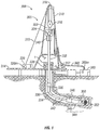
- Well operation system 300 includes a drilling rig 305 depicted schematically as a land rig, but other rigs (e.g., offshore rigs and platforms, jack-up rigs, semisubmersibles, drill ships, and the like) are within the scope of the disclosure.
- the rig 305 includes a derrick 310 that is supported above a rig floor 314.
- the rig 305 also includes lifting apparatus comprising a crown block 316 mounted to derrick 310 and a traveling block 318 interconnected by a cable 319 that is driven by a drawworks 320 (with a motor or motors 320m) to control the upward and downward movement of the traveling block 318.
- Traveling block 318 carries a hook 322, which suspends a top drive system 324.
- a power swivel may be used instead of a top drive.
- the top drive system 324 rotates a drive shaft 332, which rotates a drill string 330 within a borehole 334.
- the top drive system 324 can be operated to rotate the drill string 330 in either direction.
- the drill string may be rotated by a motor-driven rotary table 338 disposed in a drill floor (e.g., rig floor 314).
- the drill string 330 is coupled to the top drive system 324 through an instrumented subsystem 340 which includes sensors that provide drilling parameter information.
- a control system and user interface 312 controls operations of the rig 305.
- Well system 300 further includes clamping device 1 for grasping and suspending drill string 330 and/or drive shaft 332 during assembly and disassembly.
- Clamping device 1 is positioned and mounted around borehole 334 on the rig floor 314 or is coupled to another component, such as a rotary table 338. Clamping device 1 can be installed or removed during well operations, as may be required.
- the drill string 330 may be any typical drill string and, in one aspect, includes a plurality of interconnected sections of drill pipe 342, a bottom hole assembly (BHA) 344, which can include stabilizers, drill collars, and/or a suite of measurement while drilling (MWD) instruments including a steering tool 346 to provide bit face angle information.
- BHA bottom hole assembly
- MWD measurement while drilling
- a bent sub 348 is used with a downhole or mud motor 350 and a drill bit 352.
- Borehole 334 may have borehole casing 336, comprising primarily cement and pipe.
- drilling fluid is delivered to the drill string 330 through a mud hose 362 by mud pumps 360 which are driven by motor or motors 360m.
- the drill string 330 is rotated within borehole 334 by the top drive system 324, the rotary table 338, the mud motor 350, or combinations thereof.
- the cuttings produced as the bit 352 drills into the earth are carried out of borehole 334 by drilling mud supplied by the mud pumps 360.
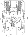
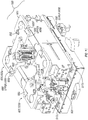
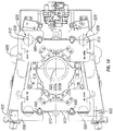
- FIG. 2 is a perspective view of a clamping device 1 for supporting components of a downhole well string.
- Clamping device 1 comprises a clamp mechanism 8, a drive mechanism 10, and a support structure 3.
- Drive mechanism 10 operates clamp mechanism 8 to engage or disengage from a component of well string 330 (here a drill pipe joint 2).
- Support structure 3 holds clamp mechanism 8 and drive mechanism 10 together and supports them and joint 2 against a rotary table 338, the rig floor 314, or another receiving structure.
- support structure 3 includes a substantially rigid rectangular base plate 4, a substantially annular base plate adapter 12 attached to the bottom of base plate 4, and a plurality of adapter pins 14 attached to and extending downward, beyond the lower surface of base plate adapter 12.
- the annular-shaped base plate adapter 12 in Figure 3 is configured to fit into a receiving structure, such as a master bushing in a rotary table, e.g. rotary table 338.
- Base plate adapter 12 can assume several different configurations to match any receiving structure. Some portion of base plate 4 may also be in contact with and be supported directly by the receiving structure.
- Base plate adapter 12 includes a slot 5' corresponding to slot 5 in base plate 4, which will be described later.
- the spacing and the cross-sectional shape of adapter pins 14 are configured to match receiving holes or slots (not shown) in the receiving structure.
- the base plate 4 has a slot 5 extending in the direction of the longest dimension of base plate 4.
- Slot 5 is keyhole shaped and includes a central opening 7 and an intersecting side opening 9.
- the central opening 7 is located at or near the center of base plate 4 and is contiguous with the side opening 9.
- Side opening 9 runs from the central opening 7 to an outer edge 11 of the base plate 4.
- the diameter of central opening 7 is larger than the largest diameter component that will be held by clamping device 1.
- Base plate 4 has two outer edges 11' that are parallel to side opening 9 and perpendicular to edge 11.
- top surface 15 of base plate 4 is horizontally disposed and includes two symmetrical, partial depth slots or "base plate channels" 6, one on each side of side opening 9. The majority of the length of each base plate channel 6 runs parallel to side opening 9, but the end of base plate channel 6 that is nearest outer edge 11 extends away from side opening 9 to edges 11' at an obtuse angle.
- guide strips 200, 201, 202, 203 are attached in between and parallel to side opening 9 and the two base plate channels 6.
- clamp mechanism 8 comprises a plurality of clamps that oppose each other and radially engage joint 2 ( Figure 2 ) to suspend within central opening 7 joint 2 and the well string components that are attached.
- Clamp mechanism 8 is slidably mounted on top surface 15 of the base plate 4.
- clamp mechanism 8 has a primary clamp body 17 and two auxiliary clamp bodies 73, 75.
- Auxiliary clamp bodies 73, 75 are positioned opposite to the primary clamp body 17 and interconnected by pin 109 when they are configured to grasp the joint.
- clamp bodies 17, 73, 75 are held and controlled by drive mechanism 10 and move parallel to top surface 15 of base plate 4.
- primary clamp body 17 has a generally rectangular shape with recesses to receive components of drive mechanism 10 as discussed below.
- Primary clamp body 17 has a front face 19 facing central opening 7, a top face 23, a back face 39, and two through-holes 16, 18 with central axes 16', 18' that extend parallel to side opening 9 of slot 5 in base plate 4.
- One hole 16 and its central axis 16' is on one side of side opening 9 and the other hole 18 and its central axis 18' is on the other side of side opening 9.
- a plurality of pivotable die insert holders 24 with imbedded die inserts 25 are mounted within recessed, curved surfaces 19' on front face 19 of primary clamp body 17.
- the die inserts 25 grip joint 2 that is received in the central opening 7.
- die inserts 25 are held in place by two endplates 21.
- One endplate 21 is mounted on the top face 23 of primary clamp body 17, and the other endplate (not shown) is mounted to the bottom side of primary clamp body 17.
- Auxiliary clamp bodies 73, 75 are joined by pin 109 to form a structure of similar size and purpose as primary clamp body 17.
- Auxiliary clamp bodies 73, 75 are disposed on the opposite side of central opening 7 from primary clamp body 17 and span across side opening 9 in base plate 4 when joined by pin 109.
- auxiliary clamp bodies 73, 75 include interlocking ribs 78, 80, respectively.
- Pin 109 is disposed through ribs 78, 80.
- Auxiliary clamp bodies 73, 75 further include pivot joints 99, 100 that are disposed near central opening 7 of base plate 4, and rotatable joints 104, 114 closer to the outer edges of base plate 4, i.e. edges 11 and 11'.
- rotatable joints 104, 114 include extended pins (not shown) that extend down into base plate channels 6.
- extended pins of pivot joints 104, 114 do not pass through base plate 4, but they do travel in base plate channels 6.
- Pivot joints 99, 100 and rotatable joints 104, 114 all have vertical axes that are perpendicular to the top face 15 of base plate 4.
- pivot joints 99, 100 in the region that includes pivot joints 99, 100, horizontal (i.e. parallel to top face 15) and generally rectangular slots 74, 76 are machined into auxiliary clamp bodies 73, 75, so as to separate pivot joints 99, 100 into an upper and a lower section to receive a member of drive mechanism 10.
- Pivot joints 99, 100 are independent of and unattached to base plate 4.
- horizontal, rectangular slots 74', 76' ( Figure 2 ) are machined into auxiliary clamp bodies 73, 75, so as to separate pivot joints 104, 114 into an upper and a lower section to receive a member of drive mechanism 10.
- auxiliary clamp bodies 73, 75 have concave, vertically-extending surfaces 79, 81 on which insert carriers 83, 85, respectively, are mounted.
- the back surface of insert carriers 83, 85 conform to concave, vertical surfaces 79, 81.
- Insert carriers 83, 85 generally face central opening 7 in base plate 4 and generally are circumferentially aligned with central opening 7.
- Insert carriers 83, 85 have a plurality of concave, vertically-extending surfaces 87, 89 that face central opening 7.
- a plurality of smaller die insert holders 90, 92 are mounted on surfaces 87, 89, respectively.
- Die insert holders 90, 92 hold die inserts 91, 93 which have toothed surfaces to grip the circumference of joint 2.
- the back surface of die insert holders 90, 92 conform to concave, vertical surfaces 87, 89 of insert carriers 83, 85.
- the described gripping elements and the curved surfaces incorporated within primary clamp body 17 and auxiliary clamp bodies 73, 75 allow the orientation of die inserts 25, 91, 93 to adjust automatically to the curved surfaces of joint 2 if joint 2 falls within a prescribed range of diameters. Gripping elements are shown and described in U.S. Patent Nos. 6,971,283 and 7,748,297 .
- drive mechanism 10 comprises a pair of parallel spindles 45, 47, pair of drive motors 27, 29, pair of drive gears 41, 43, pair of locknuts 61, 63, and a pair of fluid-powered cylinders 103, 105.
- Drive gears 41, 43 are more easily seen in Figure 6 .
- the drive control system for drive mechanism 10 will be described subsequently. Components that are used in a pairs in this embodiment may be used in greater numbers in other embodiments.
- Spindles 45, 47 have leading ends 95, 97, trailing ends 96, 98, and central axes 45', 47' which are co-axial with central axes 16', 18' in primary clamp body 17 and are therefore parallel to side opening 9 in base plate 4.
- Threads 49, 51 extend from trailing ends 96, 98 across a majority of the lengths of spindles 45, 47.
- the leading end 95 of spindle 45 is inserted into rectangular slot 74 within the auxiliary clamp body 73, and the leading end 97 of spindle 47 is inserted into a rectangular slot 76 within the auxiliary clamp body 75.
- the leading ends 95, 97 are coupled to the auxiliary clamp bodies 73, 75 via pivot joints 99, 100. With this arrangement, spindles 45, 47 are fixed to prevent rotation with respect to spindle central axes 45' and 47'.
- spindles 45, 47 are co-axial with holes 16, 18.
- Spindles 45, 47 slidably engage the smooth and unthreaded through-holes 16, 18 and can move linearly, relative to primary clamp body 17.
- primary clamp body 17 can slide axially relative to spindles 45, 47.
- Trailing ends 96, 98 of spindles 45, 47 also slidably engage mounting bracket holes 32, 34 in the vertical portion of the L-shaped mounting brackets 31, 33, which are attached near the end of base plate 4 that is furthest from outer edge 11, as best shown in Figure 2 .
- Holes 16, 18 and mounting bracket holes 32, 34 may include a smooth bushing to reduce friction.
- drive mechanism 10 includes two drive motors 27, 29 that operate simultaneously, but rotate in opposite directions.
- Drive motors 27, 29 are mounted on the top surface 15 of the base plate 4 and include drive shafts that extend parallel to spindle axes 45', 47', and are disposed near spindle trailing ends 96, 98.
- the drive motors 27, 29 may be secured to the base plate 4 using mounting brackets 31, 33, or other suitable mounting fixtures.
- drive motors 27, 29 are hydraulically-powered motors, however other types of motors, e.g., electrically-powered motors, may instead be employed.
- Drive gears 41, 43 respectively are coupled to drive motors 27, 29 and are disposed near spindle trailing ends 96, 98.
- Locknuts 61, 63 are mounted on spindles 45, 47 and have internal threads that engage with spindle threads 49, 51. As a result, the locknuts 61, 63 rotate and translate on spindles 45, 47. Locknuts 61, 63 are also adjacent to and matingly engaged with the drive gears 41, 43. As more clearly shown in Figure 6 , locknuts 61, 63 have external teeth 65, 67 that mesh with and slide along the surface of the elongated, external teeth 69, 71 of drive gears 41, 43 and remain engaged with teeth 69, 71 while sliding.
- drive gears 41, 43 when drive gears 41, 43 are rotated by drive motors 27, 29, the drive gears 41, 43 rotate locknuts 61, 63, and the rotating locknuts 61, 63 move along spindles 45, 47 while simultaneously sliding along elongated external teeth 69, 71.
- Drive gears 41, 43 are positioned on opposite sides of their respective spindle 45, 47. That is to say, one drive gear is on the right-hand side of its spindle and the other drive gear is on the left-hand side of its spindle.
- drive motors 27, 29 must rotate in opposite directions for Locknuts 61, 63 to travel the same direction simultaneously.
- Threads 49, 51 on spindles 45, 47 and the mating internal threads of locknuts 61, 63 have a small enough thread angle so that locknuts 61, 63 will only rotate on the respective spindle 45 or 47 when a tangential force is applied, such as the tangential force applied by of a rotating drive gear 41 or 43. Locknuts 61, 63 will not rotate when an axial force is applied, such as the reaction force exerted by clamp body 17 while grasping joint 2. Hence the term "locknut” is used to describe components 61 and 63.
- locknuts 61, 63 can travel along spindles 45, 47 in a forward direction toward central opening 7 pushing back face 39 of the primary clamp body 17.
- the motion of primary clamp body 17 stops when it engages a joint 2 in central opening 7.
- locknuts 61, 63 can also travel in a backward direction until they are stopped by engagement with the mounting fixtures 31, 33. Because locknuts 61, 63 are not affixed to primary clamp 17, locknuts 61, 63, in this embodiment, do not pull clamp 17 to retract it. Instead, clamp 17 is retracted away from central opening 7 by the force of fluid powered cylinders 103, 105.
- drive mechanism 10 further includes fluid powered cylinders 103, 105.
- Fluid powered cylinder 103 is coupled at one end to the primary clamp body 17, via a pivot joint 102, and at another end to the auxiliary clamp body 73, via a rotatable joint 104.
- fluid powered cylinder 105 is also coupled at one end to the primary clamp body 17, via a second pivot joint 112, and is coupled at another end to the auxiliary clamp body 75, via a rotatable joint 114.
- the fluid powered cylinders 103, 105 are hydraulic cylinders in the embodiment shown, but may be pneumatic cylinders.
- the fluid powered cylinders 103, 105 are examples of linear actuators.
- linear actuators including those not powered by fluid, may be used to accomplish the same purpose as the fluid powered cylinders 103, 105.
- fluid powered cylinders 103, 105 are aligned parallel to spindles 45, 47.
- drive control system 180 provides hydraulic fluid to drive the sometimes simultaneous movements of fluid powered cylinders 103, 105, drive motors 27, 29, and to detect and react when a joint 2 is gripped in central opening 7.
- Clamping device 1 includes a force detection mechanism 115 ( Figure 8 ) for sensing when the locknuts 61, 63 are pushing primary clamp body 17 toward the central opening 7 and when, at the same time, one of the die insert holders 24 is closed against a joint (die insert holder 24a in Figure 8 ).
- Force detection mechanism 115 is incorporated into primary clamp body 17 near back face 39 and comprises hydraulic control block 20, cartridge valves 116, 118, 120, push pins 122, 124, 126, levers 128, 130, wear elements 132, 134, spring-loaded pin 136, and pilot line 138 for high pressure hydraulic fluid handling. Wear elements 132, 134 are attached to the leading end of locknuts 61, 63.
- Hydraulic control block 20 incorporates the aforementioned cartridge valves 116, 118, 120, push pins 122, 124, and hydraulic passageways for control signals, including pilot line 136. Pilot line 136 communicates high pressure hydraulic fluid within force detection mechanism 115 to provide a signal to the other portions of the drive control system 180 when a joint 2 has been gripped by clamp mechanism 8 ( Figure 2 ).
- Figure 9 shows a schematic of a drive control system 180 for controlling operation of clamping device 1.
- Fluid supply line 139 conveys pressurized hydraulic fluid from a pump or a supply reservoir (not shown) to pressure reducing valve 141 (set to the system operating pressure), which feeds a directional control valve (four-way, three-position, four-port) 140.
- a pressure relief valve 143 (set to the system safety pressure) is disposed between pressure reducing valve 141 and directional control valve 140 to protect the system against over-pressurization.
- valves 141, 143 may be set to 13790000 Pa (2000 psi) and 15168000 Pa (2200 psi), respectively.
- Directional control 140 is also connected to fluid powered cylinders 103, 105 via fluid lines 142, 144.
- Directional control valve 140 determines whether fluid powered cylinders 103, 105 extend or retract, and determines the rotational direction of drive motors 27, 29.
- directional control valve 140 supplies pressurized fluid to fluid line 142, fluid enters the rod ends of fluid powered cylinders 103, 105, which retract, causing clamp bodies 17, 73, 75 to be drawn together towards joint 2 ( Figure 8 ).
- fluid line 144 fluid enters the cap ends of fluid powered cylinders 103, 105, which extend, causing clamp mechanism 8, i.e. clamp bodies 17, 73, 75 to move apart, and thus to release joint 2.
- a pressure reducing valve 145 is disposed in the fluid lines 144 and 144' leading to the cap end of fluid powered cylinders 103, 105 and to drive motors 27, 29 (via valve 153) to provide low pressure fluid during opening of clamp bodies 17, 73, and 75.
- reducing valve 145 may be set at 3447400 Pa (500 psi).
- fluid flowing in the opposite flow direction i.e. returning from line 144' to line 144, bypasses valve 145, choosing instead to travel through check valve 164.
- a directional control valve (three-way, two-position, three-port) 146 is disposed in the fluid line 142 to control the rate at which fluid fills the cap-end of the cylinders 103, 105 while cylinders 103, 105 extend to open clamp mechanism 8.
- first, directional control valve 140 delivers fluid to fluid lines 144 and 144'.
- directional control valve 146 is shifted to a first or "opening" position by the integrated spring within valve 146, as configured in the position shown in Figure 9 .
- the "opening" position of valve 146 is equivalent to its "home" position.
- directional control valve 146 discharges fluid from the rod ends of the cylinders 103, 105 through spring-loaded check valve 149 and into the pressurized line 144' that is filling the cap ends. This is possible because on the rod ends of cylinders 103, 105, the area of the pistons that pushes and discharges hydraulic fluid is annular. Therefore, rod-end area is smaller than the full circular area of the same piston at the cap end.
- the resulting fluid pressure in the rod end is equal to the force exerted by the piston divided by the area of the rod end of the piston.
- fluid from the rod end is then capable of traveling through directional control valve 146, through spring-loaded check valve, and into fluid line 144'.
- the additional volumetric flow of fluid to the cap end of cylinders 103, 105 increases the rate of extension. It should be noted that for every unitary distance of travel (e.g. 0.03 meters or one inch) of a piston, the rod end will discharge less fluid than is required to fill the expanding cap end, so fluid can continue to flow from both check valve 149 and fluid line 144.
- directional control valve 146 When shifted to a second or "closing" position, directional control valve 146 is set to close the clamp mechanism 8 by directing fluid to the rod ends of cylinders 103, 105.
- directional control valve 140 must first deliver pressurized fluid to fluid line 142.
- Line 142 then pressurizes fluid pilot line 168, which changes the position of directional control valve 146. Described with reference to Figure 9 , the internal piston of valve 146 would be shifted to the right.
- fluid in line 142 is ready to enter valve 146.
- directional control valve 146 allows fluid from line 142 to pass but has no other influence on the fluid flow rate to cylinders 103, 105. Therefore cylinders 103, 105 constrict (retract) at a "normal" speed, a speed influenced by the system pressure.
- the clamp body 17 and the coupled pair of clamp bodies 73, 75 draw closer to each other.
- directional control valve 146 could remain in the second position so that line 142 was always in communication with the rod-end of cylinders 103, 105.
- the extension and retraction of cylinders 103, 105 would occur at the same "normal" speed, a speed influenced by the system pressure.
- Fluid lines 148 and 148' connect fluid line 142 to one of the sides of each of the drive motors 27, 29.
- the other sides of the drive motors 27, 29 are connected to the fluid line 144' via fluid line 152.
- the motors are individually plumbed so that for a given mode of operation, they rotate in opposite directions.
- Drive motors 27, 29 each rotate in opposite, prescribed directions in response to fluid pressure in the fluid line 148 to close clamp mechanism 8.
- Both drive motors 27, 29 reverse their directions in response to fluid pressure in the fluid line 152 to open clamp mechanism 8. After both motors 27, 29 reverse, drive motor 27 once again rotates in an opposite direction from drive motor 29.
- Shut off valves 151, 153 are disposed in the fluid lines 148, 152 to isolate drive motors 27, 29 when operating in the "removal mode" ( Figure 4 ), described below.
- a pressure reducing valve 150 is disposed in between the fluid line 148 and fluid line 148' to limit the pressure reaching drive motors 27, 29 to a predetermined value, e.g., 3447400 Pa (500 psi) while closing clamp mechanism 8.
- a predetermined value e.g., 3447400 Pa (500 psi)
- Pressure reducing valve 150 has no effect on the pressure and speed of cylinders 103, 105. It was already stated that another pressure reducing valve, valve 145, reduces the pressure for both drive motors 27, 29 and cylinders 103, 105 while opening clamp mechanism 8.
- the motors 27, 29 operate at a low pressure regulated by valve 150. After contacting and grasping a joint, as detected through cartridge valves 116, 118, 120, the motors 27, 29 are switched to a high torque clamping mode via the pilot line (138 in Figure 8 ). To describe how the high torque clamping mode operates, the requisite plumbing will first be explained.
- Each of the cartridge valve 116, 118, 120 has three active ports "A,” “B,” and “C.” The first port, port-A, is shown at the top of each cartridge valve 116, 118, 120 in Figure 9 .
- the first port, port-A acts as normally-connected discharge port and is connected to a fluid return line 154, which is connected to a fluid return line 156, leading back to the hydraulic fluid reservoir.
- the second or inlet port of cartridge valve 116, port-B receives fluid from cartridge valve supply line 142', which is fed from directional control valve 140 via fluid line 142.
- the third port of cartridge valve 116, port-C is connected in series to port-B of cartridge valve 118.
- port-C of cartridge valve 118 is connected in series to port-B of cartridge valve 120.
- port-C of cartridge valve 120 is connected to pilot line 138 and sequence valve 155.
- the other end of pilot line 138 is connected to the control signal input on pressure reducing valve 150, which controls the pressure of the fluid in line 148' that is delivered to drive motors 27, 29.
- sequence valve 155 which is set at a predetermined pressure, e.g., 12066000 Pa (1750 psi), passes the high pressure signal via a fluid line 160 to a grip indication device 158 and control panel 170, notifying the operator and/or other components of the drive control system 180 that a joint 2 is being gripped by clamping device 1. Subsequently, drive control system 180 could communicate the message from sequence valve 155 or from grip indication device 158 to the control system and user interface 312 of well operation system 303.
- a predetermined pressure e.g. 12066000 Pa (1750 psi
- grip indication device 158 is a spring-return, single-acting cylinder.
- other types of indication devices may be used instead, e.g., a pressure switch.
- the location of the control valve 140, pressure reducing valve 141, relief valve 143, and signaling or grip indication device 158 can be on a separate drive system control panel 170, which may be equipped with several options to control safety "interlocks" for clamping device 1 or to communicate with control system and user interface 312, which has over-all control of well operation system 300.
- Drive system control panel 170 may be equipped with the capability to control other tools like Power Slips (not shown).
- Clamping device 1 has three primary modes within its operational sequence or cycle. These modes are operationally-closed, operationally-open, and removal. The modes will be discussed sequentially. The physical arrangement and purpose of the mode will be first described. Then the method of transitioning to the mode from the previous mode will be described.
- clamp mechanism 8 radially engages a pipe joint 2, which may be a component of a well string, such as drill string 330 in Figure 1 .
- a pipe joint 2 which may be a component of a well string, such as drill string 330 in Figure 1 .
- the additional components attached below the joint 2 could extend into borehole 334 below clamping device 1.
- the clamp mechanism 8 is capable of gripping joints and other components with diameters falling within a predefined range of diameters, e.g. 0.15 to 0.25 meters (6 to 10 inches) in one embodiment. This gripping range is particularly useful in the case of a bottom-hole assembly that may include components with different diameters.
- the predefined range can encompass all the different diameters present in the bottom-hole assembly.
- the clamp mechanism 8 would simply be opened further or closed further by the drive mechanism 10 to grip the different parts of the bottom-hole assembly, e.g., during running of a bottom-hole assembly 344 into borehole 334 or retrieval of the bottom-hole assembly 344 from borehole 334. Adjustment of the clamp mechanism 8 does not require replacing or removing any parts of the clamp mechanism 8 for diameters falling within the predefined range.
- parts of the clamp mechanism 8, such as insert carriers 83, 85 can be replaced. After the replacement of parts, the clamp mechanism 8 would grip joints with diameters falling within the new predefined range.
- the predefined ranges of diameters that can be selected for clamping include 0.10 to 0.15 meters (4 to 6 inches), 0.15 to 0.25 meters (6 to 10 inches), and 0.20 to 0.30 meters (8 to 12 inches); however other ranges are possible.
- Clamping device 1 can hold vertical loads (e.g., the weight of joint 2 and other joints and components attached to joint 2), horizontal forces, and clockwise or counterclockwise torque applied along the axis of joint 2.
- clamping device 1 can be used as a back-up tool when making-up or breaking-out connections between joints.
- the clamping force holding joint 2 is determined by the hydraulic pressure applied to drive mechanism 10 and is independent of the weight of joint 2 and independent the weight of the drill string that may be attached to joint 2. This ability to specify the clamping force independent of the load is provided to allow the system to support greater load weights without crushing the clamped component, e.g. joint 2. This differs from the conventional use of slips where the gripping force on the component is directly related to the weight being supported and where excessive radial force is sometimes applied to the supported component.
- clamping device 1 may be coupled to any suitable structure, e.g., rotary table 338 or rig floor 314 above borehole 334.
- base plate adapter 12 When clamping device 1 is mounted to a receiving structure by means of base plate adapter 12 under base plate 4, base plate adapter 12 will be able to transfer to the receiving structure the vertical, horizontal, and torque loads concurrently or separately applied to the clamp mechanism 8 by the supported load.
- a portion or all of base plate 4 may be in contact with and be supported directly by the receiving structure.
- the load forces and torque from the supported load will be transferred from the clamp mechanism 8 to guide strips 200, 201, 202, 203 ( Figure 7 ) and to drive mechanism 10, including mounting brackets 31, 33, and to joints 104, 114.
- the load forces and torque are next transferred to base plate 4, including base plate channels 6, in which joints 104, 114 rest, and then to base plate adapter 12, and to the receiving structure.
- the operationally-open mode of clamping device 1 is best described with reference to Figure 5 .
- the die inserts 25, 91, 93 have disengaged from the joint, which is no longer shown in the central opening 7. Carried by primary clamp body 17 and auxiliary clamp bodies 73, 75, the die inserts 25, 91, 93 have moved away from the center of the central opening 7 to its periphery.
- cylinders 103, 105 are moved to the extended position.
- Extension of cylinders 103, 105 moves the pair of auxiliary clamp bodies 73, 75 and the single primary clamp body 17 away from each other, in a direction parallel to the base plate 4, and away from the center of the central opening 7.
- the drive gears 41, 43 rotate to drive the locknuts 61, 63 in a reverse direction.
- the locknuts 61, 63 are driven in the reverse direction, they rotate and translate along the spindles 45, 47 until they abut the mounting brackets 31, 33.
- locknuts 61, 63 are not attached to primary clamp body 17 and therefore do not pull primary clamp body 17 away from central opening 7.
- auxiliary clamp bodies 73, 75 may first reach the left side of base plate 4, or primary clamp body 17 may first reach the right side of base plate 4, or these events could happen simultaneously. Later, when changing to the operationally-closed mode, this lateral "floating,” allows clamp mechanism 8 and drive mechanism 10 to self-center on a joint 2 dispose in central opening 7, even if joint 2 is not in the middle of central opening 7. In the operationally-open mode, like the operationally-closed mode, the cylinders 103, 105 remain parallel to the spindles 45, 47.
- FIG. 4 The removal mode or fully-open position of clamping device 1 is shown in Figure 4 .
- the connecting pin 109 ( Figure 2 ) has been removed from the auxiliary clamp bodies 73, 75, and auxiliary clamp bodies 73, 75 have been rotated about the pivot joints 99, 100 and relative to the base plate 4.
- slot 5 in base plate 4 is not obstructed, and lateral access to the central opening 7 is possible via the side opening 9.
- the entire clamping device 1 can be removed from or placed over borehole 334, whether or not a drill string 330 is already disposed in borehole 334 and possibly extending out from borehole 334.
- the central opening 7, when aligned with borehole 334, can receive joint 2 of drill string 330 that is disposed in borehole 334 or being run into or removed from the borehole 334.
- the clamping device 1 Before changing to the removal mode, the clamping device 1 must be first placed in the operationally-open mode so that auxiliary clamp bodies 73, 75 are fully positioned at the left side of base plate 4.
- drive motors 27, 29 are isolated from hydraulic fluid pressure by shut-off valves 151, 153 and do not rotate so as to keep pivot joints 99, 100 at their current positions without moving laterally.
- Pin 109 is removed from the auxiliary clamp bodies 73, 75.
- Fluid powered cylinders 103, 105 are then retracted. This imparts a rotational motion on auxiliary clamp bodies 73, 75 about the pivot joints 99, 100, and auxiliary clamp bodies 73, 75 move outwardly and away from slot 5.
- auxiliary clamp bodies 73, 75 rotate, the extended pins (not shown) of rotatable joints 104, 114 move out from the side openings of the base plate channels 6 and away from base plate 4.
- the central opening 7 is accessible through the side opening 9, and the die inserts 25, 91, 93 are not positioned to grip a joint disposed in the central opening 7.
- clamping device 1 can be removed from a position above the borehole 334 by moving it laterally. This feature is particularly useful if there are other structures or pieces of equipment above borehole 334.
- the design of clamping device 1 makes it possible to remove clamping device 1 from a position above borehole 334 with little or no disturbance to the other structures or equipment vertically-aligned and overhead. The same is true when installing clamping device 1 above borehole 334, which is also accomplished using the "removal mode.” In the removal mode, the cylinders 103, 105 move to a position that is angled, and thus no longer parallel, relative to the spindles 45, 47.
- cylinders 103, 105 are extended while drive motors 27, 29 are isolated and not rotating. This swings the auxiliary clamp bodies 73, 75 towards the slot 5.
- the extended pins of rotatable joints 104, 114 enter and move through the side openings of the base plate channels 6 and toward side opening 9 of slot 5.
- Auxiliary clamp bodies 73, 75 return to their former position in the operationally-open mode ( Figure 5 ). The auxiliary clamp bodies 73, 75 can then be secured together using the connecting pin 109.
- cylinders 103, 105 contract and move auxiliary clamp bodies 73, 75 relative to primary clamp body 17.
- clamp bodies 17, 73, 75 move towards central opening 7.
- drive gears 41, 43 rotate locknuts 61, 63 so that the locknuts travel along spindles 45, 47 towards central opening 7.
- the locknuts 61, 63 engage and push primary clamp body 17 in the same direction.
- die inserts 25, 91, 93 associated with clamp bodies 17, 73, 75, radially grip the joint 2 that is disposed in the central opening 7.
- the positions of the die inserts 25, 91, 93 are self-adjustable to accommodate a large-diameter well string component or a small-diameter component within a pre-defined range of diameters.
- clamp bodies 17, 73, 75 move parallel to the base plate 4 and toward or away from the center of the central opening 7, the positions of the die inserts 25, 91, 93 adjust to match the diameter of the joint to be gripped.
- the spindles 45, 47 and guide strips (200, 201, 202, 203) define the parallel linear paths along which clamp bodies 17, 73, 75 travel.
- the cylinders 103, 105 are parallel to the spindles 45, 47 and to each other and are in the retracted position.
- Both the fluid powered cylinders 103, 105 and the drive motors 27, 29 apply clamping force to the clamp bodies 17, 73, 75 when the clamp bodies 17, 73, 75 engage a joint.
- the locknuts 61, 63 are engaged with the back face 39 of the primary clamp body 17.
- the locknuts 61, 63 and spindles 45, 47 mechanically lock the clamp bodies 17, 73, 75 in any (variable) position to accommodate the joint size. Locknuts 61, 63 hold their position along spindles 45, 47 even if the power to drive motors 27, 29 is lost. This locking is a mechanical back-up safety feature in case there is a power failure in drive control system 180.
- indication device 158 is used to indicate when clamping device 1 is in the operationally-closed mode, i.e. is gripping a joint 2. Clamping device 1 is in the operationally-closed mode when all the valves 116, 118, 120 are activated. In this mode, high pressure fluid is supplied to drive motors 27, 29 (via the pilot line 138) to enable the clamp mechanism 8 to tighten its grip on joint 2.
- Clamping device 1 may be used in conjunction with well operation system 300 during any or during several stage(s) of operation. For example, it may be used during investigative probing, during initial drilling, during continuation drilling after casing and cement have been added to some or all of a borehole, and/or during production. Consequently, clamping device 1 may be used with exploratory wells, production wells, or other well-related operations.
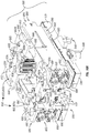
- FIG 10A is a front perspective view of a clamping device 500 for supporting components of a downhole well string.
- Figure 11 is a rear perspective view of a clamping device 500.
- Clamping device 500 generally comprises support structure 505, a clamp mechanism 650, and a drive mechanism 800.
- Drive mechanism 800 operates clamp mechanism 650 to engage or disengage from a component of well string.
- Support structure 505 couples together clamp mechanism 650 and drive mechanism 800, and supports them and the well string component against a rotary table 338 or the rig floor 314 ( Figure 1 ), or another receiving structure.
- support structure 505 includes a substantially rigid, generally rectangular, upper base plate 510, a substantially rigid, generally rectangular lower base plate 570, a keyhole-shaped slot 520, a plurality of pneumatic bellows 590, a plurality of stroke-limiting base plate guide assemblies 605, and a plurality of adapter lugs 508 attached to and extending downward beyond the bottom surface of the lower base plate 570.
- Keyhole-shaped slot 520 comprises a central opening 522 and a side opening 524 and extends through the entire support structure 505. Keyhole-shaped slot 520 receives components of a downhole well string. The configuration of keyhole-shaped slot 520 will be described in greater detail below.
- upper base plate 510 includes a horizontal top surface 512, an outer edge 514 (the front edge), two long outer edges 516, and a keyhole-shaped slot 520a.
- Keyhole-shaped slot 520a extends in the direction of the longest dimension of upper base plate 510 and includes a central opening 522a and an intersecting a side opening 524a.
- the center 523a ( Figure 14 ) of central opening 522a is located at or near the center of upper base plate 510.
- Central opening 522a is contiguous with the side opening 524a.
- Side opening 524a runs from the central opening 522a to outer edge 514 and divides outer edge 514 into two portions.
- the diameter of central opening 522a is larger than the largest diameter joint to be held by clamping device 500.
- the top surface 512 includes two T-slots 535, one on each side of side opening 524a and running the entire length of upper base plate 510.
- two L-shaped recesses 540 are formed near to and including the entire outer edge 514, one on each side of side opening 524a.
- L-shaped recess 540 intersects and thus removes a portion of T-slot 535. Equivalently stated, T-slot 535 terminates into the L-shaped recesses 540.
- Each L-shaped recess 540 includes a vertical V-shaped indentation 542 near the end of T-slot 535. Together, recess 540 and indentation 543 provide clearance to lower a double-L latch 690 at the bottom of a clamp body 655 before removing clamp body 655. Components 690 and 655 appear in Figure 10A are described below.
- upper base plate 510 Disposed along all edges of upper base plate 510, e.g. outer edge 514 and outer edge 516 as shown in Figure 12 , are a plurality of small, tapped holes 532 to threadingly engage machine screws used to attach base plate side covers 530 ( Figure 10A ).
- upper base plate 510 includes additional features for receiving and attaching other members of clamping device 500.
- three recesses 546 are formed into surface 512 for receiving end-stops 547, discussed below.
- End-stop recess 546a is disposed along outer edge 514 and in line with T-slots 535.
- End-stop recess 546b is nearly aligned with the center 523 of central opening 522a in one direction and is evenly spaced between T-slots 535 and the nearest outer edge 516 in the other direction.
- End-stop recess 546c is disposed near the edge of upper base plate 510 that is opposite outer edge 514.
- Two slots 548 are formed to matingly receive guide strips 550 ( Figure 15 ).
- Guide strips 550 and their slots 548 run parallel to T-slot 535 and are nearly tangent to and lie on opposite sides of central opening 522a.
- the center of each guide strip 550 is aligned with center 523a of central opening 522a.
- guide strips 550 are positioned adjacent the region where T-slots 535 intersect central opening 522a.
- Guide strips 550 aid the movement of clamp bodies 655 in the regions where T-slots 535 do not exist and therefore cannot provide guidance.
- attachment recesses 552 for pneumatic bellows 590 are a third receiving feature formed in top surface 512.
- Five such recesses 552 are formed.
- a central hole 554 and four boreholes are machined through upper base plate 510 to access and to mount a pneumatic bellows 590.
- four bellows attachment recesses 552a are disposed evenly around central opening 522a in a rectangular pattern. Each of these four is joined in the middle of one side by an L-shaped channel 556 which is provided for a pneumatic communication line.
- a fifth bellows attachment recesses 552b is formed on the opposite side of central opening 522 from side opening 524a and has no channel for air supply.
- Four oblong holes or slots 562 with central axes 563 are disposed near the four exterior corners of upper base plate 510 to receive and attach stroke-limiting base plate guide assemblies 605 ( Figure 19 ), to be described later. Slots 562 are used instead of round holes the avoid the potential for assemblies 605 to bind while being extended or retracted.
- Upper base plate 510 further includes borehole 564 and a concentric counterbore 566 for receiving weight sensor 760, which is described below and disposed near the fifth bellows attachment recesses 522b on the opposite side from central opening 522a.
- the lower base plate 570 is disposed underneath and coupled to upper base plate 510.
- Lower base plate 570 has a horizontal top surface 572, an outer edge 574 (the front edge), two long outer edges 576, and a keyhole-shaped slot 520b extending in the direction of the longest dimension of lower base plate 570.
- Keyhole-shaped slot 520b includes a central opening 522b and an intersecting a side opening 524b.
- the center 523b of central opening 522b is located at or near the center of lower base plate 570.
- Central opening 522b is contiguous with the side opening 524b.
- Central opening 522b runs from the central opening 522b to outer edge 574 of the lower base plate 570 and divides outer edge 574 into two portions.
- Central opening 522b has a frustoconical shape: it has an upper diameter that matches the diameter of the corresponding central opening 522a on upper base plate 510, and a lower diameter that is larger than its upper diameter. In other words, the diameter of central opening 522b expands towards the bottom.
- adapter wings 578 extend horizontally away from long outer edges 576 and are disposed in a rectangular pattern around central opening 522b.
- a fifth adapter wing 578 extends horizontally away from the center of the edge opposite outer edge 574.
- Three of the adapter wings 578 have recesses where swinging lifting rings 579 are attached, best shown in Figure 12 .
- Adapter lugs 508 are attached to the bottom of adapter wings 578 in order to provide a means to engage and transfer force and torque to a receiving structure, such as rotary table 338, power slips, or other such supporting structure.
- the lower base plate 570 includes five bellows-receiving counterbores 580 that are axially aligned with the corresponding central holes 554 in the upper base plate 510.
- Each counterbore 580 has four circumferentially positioned, evenly spaced stud boreholes 581 to receive studs for retaining bellows 590.
- Four guide cylinder boreholes 584 are disposed in lower base plate 570 and are axially aligned with the corresponding central axes 563 of slots 562 in the upper base plate 510.
- a plurality of short cylindrical protrusions 582 are circumferentially disposed about central opening 522b on top surface 572. These cylindrical protrusions 582 mate with counter bore holes (not shown) in the bottom surface of upper base plate 510 and stabilize upper base plate 510 against horizontal translation when clamping device 500 supports the weight of a well string component, such as pipe joint 2.
- a plurality of pneumatic bellows 590 and a plurality of stroke-limiting base plate guide assemblies 605 couple and support upper base plate 510 above lower base plate 570.
- Pneumatic bellows 590 give a visual indication of when clamping device 500 is and is not supporting the weight of a well string 330. This visual indication is a safety feature.
- pressure in pneumatic bellows 590 increases.
- bellows 590 are relieved of air through exhaust relief valves (not shown), and bellows 590 compress.
- Upper base plate 510 settles on to lower base plate 570 as shown in Figure 20 .
- pneumatic bellows 590 there are five pneumatic bellows 590 that are mounted at their bottom end in the appropriate counterbores 580 and at their top end in the attachment recesses 522 as described with reference to Figures 12 and 13 .
- pneumatic bellows 590 includes two air pockets, however, bellows having a greater or fewer number of air pockets may be employed.
- Pneumatic bellows 590 has a circular base plate with four studs for engagement with counterbores 580 in lower base plate 570. The studs pass through boreholes 581 in lower base plate 570 to be threadingly engaged with nuts (not shown).
- pneumatic bellows 590 has studs that pass through upper base plate 510 and are threadingly engaged and held by nuts (not shown) within bellows attachment recess 552. Bellows 590 may be fastened by other means as well. Also within bellows attachment recess 552, a ninety-degree elbow pneumatic coupling 594 attaches at one end to pneumatic bellows 590 through central hole 554. The other end of pneumatic coupling 594 faces the L-shaped channel 556 for attachment to a pneumatic air line (not shown).
- guide assembly 605 is a series of axially aligned cylinders that telescopingly extend and, alternately, collapse as upper base plate 510 rises and settles under the load of drill string 330.
- guide assembly 605 comprises a lower guide sleeve 608, a middle guide sleeve 614, an upper guide rod 620, and a stroke-limiting pin 626.
- Lower guide sleeve 608 has an upper borehole 609 and a lower counter bore 610, leaving an internal, circular ledge 612 facing downwards.
- Middle guide sleeve 614 has first outer diameter 615 defining a majority of the outer surface and a larger, second outer diameter 616 confined to a small bottom section. The differing diameters 615 and 617 create an upward-facing external circular ledge 617 that contacts internal circular ledge 612 and limits the extent of vertical motion when the guide assembly 605 extends.
- Middle guide sleeve 614 also has an axial borehole 618 and a radially-aligned pin hole 619 passing horizontally through its sidewall to receive stroke-limiting pin 626.
- the upper guide rod 620 glidingly engages inside borehole 618 of middle guide sleeve 614.
- Upper guide rod 620 has a radially-aligned pin slot 612 to receive stroke-limiting pin 626.
- Upper guide rod 620 further has a radially-aligned crossbore 622 to receive guide rod retainer pin 628 and bind with upper base plate 510 ( Figure 19 ). How the components of the guide assembly 605 are assembled and the relative sizes of the various components are best shown in Figure 24 .
- stroke-limiting pin 626 passes through middle guide sleeve 614 and upper guide rod 620 to limit the upward extension of guide assembly 605.
- Clamping device 500 incorporates four guide assemblies 605 mounted at their upper end in the slots 562 in upper base plate 510.
- the lower guide sleeves 608 are attached inside guide cylinder boreholes 584 and extend beyond top surface 572 of lower base plate 570.
- the upper, extended portion of each lower guide sleeves 608 has an upper, outer diameter 613 that is less than the inner diameter of borehole 584 but matches a corresponding recess (not shown) in the bottom of upper base plate 510.
- Each corresponding recess in the bottom of plate 510 is round and shares a central axis 563 with a mating slot 562.
- clamp mechanism 650 comprises two opposing clamp bodies 655 that are moved toward one another to engage and suspend a well string component (e.g., joint 2) within central opening 522.
- clamp mechanism 650 is slidably mounted on top surface 512 of upper base plate 510.
- Clamp mechanism 650 has two similar clamp bodies 655.
- First or front clamp body 655a spans across side opening 524 and faces central opening 522 of the keyhole-shaped slot 520 in support structure 505.
- Second or rear clamp body 655b is positioned on the opposite side of central opening 522.
- Rear clamp body 655b is turned the opposite direction of front clamp body 655a and thereby also faces central opening 522.
- Clamp bodies 655a, 655b include gripping die inserts 722 that engage joint 2.
- Clamp bodies 655a, 655b are held and controlled by drive mechanism 800 and move parallel to top surface 512.
- each clamp body 655 has a generally rectangular shape and includes two pair of horizontally disposed arms 680. Each pair of arms 680 includes an upper and lower arm. Each pair of arms 680 forms a generally rectangular recesses 681 (best shown in Figure 19 ) on outwardly-facing ends of clamp body 655 to receive components of drive mechanism 800 as discussed more-fully below.
- Clamp body 655 also includes a top face 656, an internal face 660 facing generally towards central opening 522, an external face 670, and two vertical shafts 685.
- the internal face 660 includes flat regions and two concave vertically-extending surfaces 662 that share a common central edge 663 in the middle of internal face 660.
- the concave vertically-extending surfaces 662 partially face towards each other, and partially face towards central opening 522.
- Surfaces 662 begin at top face 656 and extend almost down to the bottom of clamp body 655, leaving a centrally located bottom ledge 667, best shown in Figure 21 and also shown in the elevation view of Figure 22 .
- a short, vertically-oriented carrier-retaining pin 668 ( Figure 21 ) is coupled with and extends above bottom ledge 667. The horizontal distance from the common central edge 663 to the carrier-retaining pin 668 is greater than the distance from carrier-retaining pin 668 to the outer vertical edge 664 of concave, vertical surface 662.
- upper arms 680 of clamp body 655 are flush or coplanar with top face 656 and are horizontal metal plates extending outwardly and away from side opening 524a.
- Lower arms 680 are similar but are coplanar or flush with the bottom of clamp body 655.
- the lower and upper arms 680 of clamp body 655 extend towards the outer edges 516 of upper base plate 510.
- lower and upper arms 680 define a narrow portion of the external face 670 of clamp body 655.
- Face 670 includes nearly semi-circular grooves 682a which are defined in part by a vertical central axis 698 ( Figure 15 ).
- top face 656 of clamp body 655 has rectangular recesses 658 that are adjacent to the upper edges of concave, vertical surfaces 662.
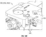
- vertical shafts 685 are imbedded within clamp body 655 generally above T-slots 535 in upper base plate 510. Vertical shafts 685 are positioned sufficiently near external face 670 so that external face 670 includes a outward curved protrusions. As best shown in Figure 10B , a small latch clearance slot 686 is disposed in clamp body 655 intersecting external face 670 below top face 656. Latch clearance slot 686 leaves a gap around a portion of vertical shaft 685. In all, four latch clearance slots 686 are so disposed in both upper and both lower corners of clamp body 685. Each slot 686 slidingly receives a double-L latch 690.
- Latch members 690 provide clearance for cylinder assembly 805 to wing laterally away from the clamp body 655 that spans side opening 524, as described below.
- the latch clearance slots 686 are sufficiently long to allow a mating member of a double-L latch 690 enough space to slide vertically.
- Four sliding locks 672 are mounted on external face 670. The shafts of sliding locks 672 move horizontally and are aligned with and are received by the four latch clearance slots 686 in the two vertical shafts 685 on clamp body 655.
- double-L latch 690 disposed on the upper, outer corners of clamp body 655 matingly receives and couples pull block 820 of the cylinder assembly 805.
- Double-L latch 690 moves vertically away from clamp body 655 in order to provide the clearance before removing a cylinder assembly 805 from clamp body 655.
- Double-L latch 690 is formed to have two L-shaped arms 692, 694, each lying in a plane perpendicular to the other and joined at the top end of each "L.”
- a large L-shaped arm 692 lies parallel to and near top face 656 and is generally positioned to extend beyond external face 670.
- the "foot” portion of the large L-shaped arm 692 extends back, along the side of adjacent lower or upper arm 680 of clamp body 655 and includes a rectangular protrusion 693 that reaches into a cut in the middle of lower or upper arm 680.
- the top of the "L” of the large L-shaped arm 692 is positioned near the top of vertical shaft 685.
- the upper end of small L-shaped arm 694 starts at this same location and extends generally vertically, with the "foot” or lower portion of the small “L” reaching towards external face 670 clamp body 655 and extending into latch clearance slot 686 around vertical shaft 685.
- the vertical shaft 685 slidingly couples with a vertical borehole in the lower portion of the small L-shaped arm 694.
- Latch clearance slot 686 is large enough to have an open gap even after vertical shaft 685 receives the small L-shaped. This gap of latch clearance slot 686 allows the entire double-L latch 690 to be raised and lowered to couple and decouple clamp body 655 from cylinder assembly 805.
- the large L-shaped arm 692 of each double-L latch 690 has a semi-circular groove 682b, which shares the vertical central axis 698 with semi-circular groove 682a of the adjacent lower or upper arm 680. Together, semi-circular grooves 682a and 682b form a generally circular hole that receives cylindrical stud 822 on pull-block 820 of cylinder assembly 805.
- Each clamp body 655 is coupled to a plurality of pivotable die retention device 720 comprises a plurality of die inserts 722, a plurality of pivotable die insert holders 724, a plurality of holder-retaining pins 730, an insert carrier 725, a plurality of carrier-retaining pins 668, and a retaining plate 734. These will be described, generally, in the reverse order.
- Each insert carrier 725 generally faces and is generally circumferentially aligned with central opening 522 in support structure 505.
- the convex back surface of insert carrier 725 conforms and slidingly mates with the concave, vertical surface 622 on a clamp body 655.
- Both ends of insert carrier 725 have a curved vertical slot 732 that matingly receives a carrier-retaining pin 668. Therefore, each insert carrier 725 is coupled by two carrier-retaining pins 668 in this embodiment.
- one of these carrier-retaining pins 668a is coupled with and extends above bottom ledge 667.
- the other carrier-retaining pin 668b ( Figure 22 ) is coupled with and extends down from one portion a retaining plate 734.
- retaining plate 734 The opposite end, at retaining plate 734, is attached inside rectangular recesses 658 below the top face 656 of clamp body 655. Furthermore, the width, length, and curvature of curved vertical slot 732 allow insert carrier 725 to pivot on carrier-retaining pins 668 and slide along concave, vertical surfaces 662. In this manner, insert carrier 725 is held by and coupled to clamp body 655.
- insert carrier 725 slidably and pivotally couples with a plurality of die insert holders 724.
- insert carrier 725 has a plurality of concave, vertical channels 728 that face opening 522.
- the convex back surface of a die insert holder 724 conforms to and is mounted against concave, vertical channel 728.
- Both ends of die insert holder 724 have a curved vertical slot 723 that matingly receives a holder-retaining pin 730 from insert carrier 725.
- the width, length, and curvature of curved vertical slot 723 allow die insert holder 724 to pivot on holder-retaining pins 730 and to slide against vertical channel 728.
- Each die insert holder 724 holds and couples a plurality of die insert 722 which, in turn, have toothed surfaces to grip the circumference of joint 2.
- pivotable gripping device 720 and the complementarily concave, vertical surfaces 622 incorporated within clamp body 655 allow the orientation of die inserts 722 to adjust automatically to the curved surfaces of joint 2 if joint 2 falls within a prescribed range of diameters.
- a plurality of leaf springs 738 are mounted on internal face 660 such that a free end extends beyond outer vertical edges 664 of concave, vertical surfaces 662. The free end of each leaf spring 738 presses against an insert carrier 725, pushing or biasing it towards common central edge 663 of concave, vertical surfaces 662.
- clamping device 500 is not engaging joint 2, the two adjacent insert carriers 725 are pushed together near common central edge 663.
- the compressive force pushing against die inserts 722 causes die insert holders 724 to slide and pivot along concave, vertical channels 728 and also causes the insert carriers to slide and pivot along concave, vertical surfaces 662 until the compressive force is more evenly distributed across all gripping surfaces, i.e. all die inserts.
- the pivotable gripping devices 720 automatically adjust to the particular diameter of the joint 2 disposed within the clamping mechanism 650 of clamping device 500.
- a weight sensor 760 indicates when clamping device 550 is supporting the weight of a joint 2 or other well string component.
- Weight sensor 760 comprises a spring-loaded contact pin 762, a retainer cap, a position switch 766 with hydraulic channels, and wheel and lever assembly 768.
- the spring-loaded contact pin 762 slidably mates with the vertical recess formed by borehole 564 and counterbore 566 in upper base plate 510 and extends above and below upper base plate 510.
- the spring-loaded contact pin 762 is held within upper base plate 510 by a retainer cap 764.
- spring-loaded contact pin 762 is tapered and contacts wheel and lever assembly 768 that is rotatably coupled with a proximity switch that is attached to the exterior face 670 of second clamp body 655b.
- a proximity switch that is attached to the exterior face 670 of second clamp body 655b.
- position switch 766 could be coupled with a similar electric position switch so that a signal could also be sent to the control system and user interface 312.
- the pneumatic bellows re-inflate with air supplied through pneumatic coupling 594, and upper base plate 510 rises, allowing the contact pin 762 to fall and to cease pressing wheel and lever assembly 768 against position switch 766, cancelling the weight signal.
- drive mechanism 800 comprises a plurality of cylinder assemblies 805.
- each cylinder assembly 805 comprises one or more of fluid powered cylinders 810, one or more pull-blocks 820, a load cell 840 for each cylinder 810, and cylinder covers 842 and 844.
- cylinder assembly 805 lies parallel to side opening 524 of the key-hole shaped slot 520.
- the front end of cylinder assembly 805 lies near the outer or front edge 514 of upper base plate 510.
- Pull-block 820 is positioned at the front end of cylinder assembly 805. As shown in Figure 25 , pull-block 820 is a generally rectangular block with its longest dimension disposed vertically.
- Generally-cylindrical studs 822 are positioned at the top and bottom of pull-block 820.
- the front face of pull-block 820 has a plurality of combination holes 824 (two are shown) formed by a borehole that receives the threaded rod-end of fluid powered cylinder 810 and a counter bore that receives a load cell 840.
- the rear vertical face (not shown) of pull-block 820 is flat. The assemblage of these components is shown in Figure 17 .
- cylinder inner cover 842 surrounds the cap-end of fluid powered cylinder 810.
- cylinder rod 814 extends toward and beyond front edge 514.
- cylinder rod 814 is coupled with pull-block 820 and load cell 840, as previously indicated.
- a large nut and washer 816 threadlingly engages the end of cylinder rod 814, tightly coupling load cell 840 and pull-block 820 on cylinder rod 814.
- a cylinder outer cover 844 is disposed around the cylinder rod 814 and is attached to pull-block 820. Outer cover 844 slides over the outside of inner cover 842 as fluid powered cylinder 810 expands and retracts.
- studs 822 of pull-block 820 couple with semi-circular grooves 682a, 682b on front clamp body 655a to form upper and lower detachable front joints 826.
- Front joints 826 couple cylinder assembly 805 with front clamp body 655a.
- cylindrical studs 812 engage the upper and lower surfaces of cylinder assembly 805. More specifically, studs 812 couple with semi-circular grooves 682a, 682b on rear clamp body 655b to form upper and lower pivoting rear joints 828.
- Rear joints 828 couple cylinder assemblies 805 with front clamp body 655b.
- Figure 23 presents a schematic of drive control system 900, which comprises directional control valve 910, fluid lines 912, 912a, 912b communicating with the rod-ends of cylinders 810, fluid lines 922, 922a, 922b communicating with the cap-ends of cylinders 810, sequence valve 926, position switch 766 (introduced earlier), pilot (signal) lines 942, 942a, 942b, time-delay cylinder 944, check valves 950 and 955, and other supporting components.
- Check valves 950 and 955 are local to the cylinder assemblies 805.
- Check valves 950 and 955 are piloted to receive a pressure signal to command the valve to allow reverse flow when required.
- Cylinder assembly 805 includes a plurality of cylinders 810 (e.g. two as described in this embodiment). For each cylinder assembly 805, a secondary safety check valves 950 is plumbed in series with a T-coupling 952 that connects the two safety check valves 955 from adjacent cylinders 810.
- drive control system 900 receives power from a pump (not shown) or another means of pressurized hydraulic fluid. Fluid is received and returned via directional control valve 910, shown at the bottom of Figure 23 . Valve 910 sets the direction of travel of cylinders 810 by adjusting the direction of fluid flow appropriately. When cylinders 810 are to be retracted to draw the two clamp bodies 655a and 655b together, pressurized fluid is directed to fluid lines 912 that communicate with the rod-ends of cylinders 810. Fluid first passes through a first filter 914.
- a portion of the fluid is directed a fluid line 943 as a pilot or control signal to reset time-delay cylinder 944.
- line 943 becomes pressurized.
- time-delay cylinder 944 will become apparent later.
- One mode of operation of cylinder 944 will be explained here.
- the appropriate end of 944 fills, pushing its internal piston or membrane and discharging fluid on the other side and back-flows through orifice 948.
- the discharging fluid travels through fluid line 942 until reaching and passing through position switch 766 which, at this time, is positioned to indicate "no weight on clamping device 500," so discharging fluid travels to and through fluid line 941 to line 922 and joins other fluid in line 922 (to be explained next) traveling back through valve 910 to the hydraulic reservoir.
- fluid from the pilot port of sequence valve 926 drains through line 942 along with the fluid from time-delay cylinder 944.
- the integral spring within valve 926 changes valve 926 from the open position to the closed position.
- Pressurized fluid travels in fluid line 912a, reaching the clamping device and its cylinder assembly 805. At this location, the fluid is again divided. Whereas a majority of the fluid continues in line 912 and passes through secondary safety check valve 950a. After valve 950, the fluid divides for a final time with a portion going to each of the two cylinder safety check valves 955a and finally to the rod-end of a coupled cylinder 810. Pressure in the rod-end causes cylinders 810 to retract, drawing the front and rear clamp bodies 655a and 655b together. In the operation mode described, check valves 950a and 955a insure that fluid can travel to the rod-end of cylinders 810 but cannot return.
- fluid is released from the cap-ends through fluid lines 922a and joins fluid line 922b when reaching fluid line 922 in the control manifold 905. Fluid passes through a check valve to by-pass sequence valve 926 and passes another check valve to by-pass second fluid filter 924. Fluid then passes through directional control valve 910 and finally back to the fluid reservoir (not shown).
- position switch 766 which acts as a weight indicating sequence valve, is triggered by the weight of the drill string 330 pulling down upper plate 510.
- Position switch 766 shifts (to the left according the configuration in Figure 23 ) and isolates line 941 so no fluid can pass from line 922 to line 941 and through position switch 766. Otherwise, at some situations while clamping device 500 is supporting weight, fluid from line 922 and 941 might otherwise pass through switch 766 and pressurize fluid pilot lines 942 and 946 that lead to the control port of sequence valve 926.
- sequence valve 926 remains in a closed position achieved earlier when line 943 was pressurized. While position switch 766 senses that there is weight on clamping device 500, pilot line 942 is connected to fluid line 958, which can drain to either line 912 or line 922 if and when the pressure in line 958 is greater. Line 958 is protected by check valves so line 958 cannot be pressurized by either line 912 or line 922.
- pressurized fluid follows nearly an opposite path, but events happen in two stages.
- a pressurized control signal is sent to check valves 950 and 955 to command them to allow reverse flow so that the rod-end of cylinders 810 can be drained.
- control valve 910 directs pressurized fluid to line 922 and allows return flow from line 912.
- Pressurized fluid in line 922 passes through filter 923 and reaches sequence valve 926, which is closed at this time, so the primary flow of fluid cannot yet reach the cap ends of cylinders 810 to expand them.
- a portion of the fluid is directed to a pilot fluid line 941 to act as control signal.
- Line 941 directs fluid to position switch 766. If clamping device 500 is not holding weight, e.g. the weight of joint 2, as indicated by weight sensor 760 ( Figure 19 ), then position switch 766 allows fluid from line 941 to enter pilot fluid line 942.
- Fluid in line 942 takes two paths. Along the first path, fluid in line 942 travels via line 942a and 942b to the safety control valves 950, 955 located near the two cylinder assemblies on clamping device 500, and releases them to allow reverse flow. As a result, the rod-ends of cylinders 810 are depressurized, but little fluid leaves them because the cap-ends have not yet been pressurized.
- the pistons of cylinders 810 are stationary during this first stage of operation.
- fluid passes through an orifice 948, reducing the flow rate as the fluid enters fluid line 946 and causing a reduction in fluid pressure.
- the purpose of the fluid in line 946 is to activate sequence valve 926 so it will allow the primary flow of fluid to continue traveling on line 922 to each the cap-ends of cylinders 810.
- a certain pressure in line 946 is required in order to activate sequence valve 926, but fluid in line 946 must first fill time-delay cylinder 944. As cylinder 944 fills, the pressure in line 946 remains lower than the activation pressure of sequence valve 926.
- sequence valve 926 switches and allows fluid to pass through to the other section of line 922 where it divides and travels in line 922a and 922b to reach the cap-end of the cylinders and to extend cylinder rods 814. Fluid from the cap-ends of cylinder 810 returns through lines 912a, 912b. This direction of travel is possible because all safety check valves 950 and 955 have been released to allow reverse flow as previously explained. Fluid merges into line 912 and reaches the control panel. Fluid passes through a check valve to by-pass first fluid filter 914 and then returns through directional control valve 910 to reach the fluid reservoir.
- Clamping device 500 has three primary modes or positions within its operational sequence or cycle. These modes are operationally-closed, operationally-open, and removal. The modes will be discussed sequentially. The requisite performance of the drive control system 900 has already been explained. Now, in this section, the purpose of each operational mode and the physical arrangement taken by various components during each mode will be described. The method of transitioning to each mode from the previous mode will be described subsequently.
- clamp mechanism 650 radially engages a component of a well string, such as pipe joint 2, which may be a component of drill string 330 in Figure 1 .
- a well string such as pipe joint 2
- the additional components attached below the joint 2 could extend into borehole 334 below clamping device 500.
- Clamp mechanism 650 is capable of gripping joints and other components with diameters falling within a predefined range of diameters, e.g. 0.15 to 0.25 meters (6 to 10 inches) in one embodiment. This gripping range is particularly useful in the case of a bottom-hole assembly that may include components with different diameters.
- the predefined range can encompass all the different diameters present in the bottom-hole assembly.
- the clamp mechanism 650 would simply be opened further or closed further by the drive mechanism 800 to grip the different parts of the bottom-hole assembly, e.g., during running of a bottom-hole assembly 344 into borehole 334 or retrieval of the bottom-hole assembly 344 from borehole 334. Adjustment of the clamp mechanism 650 does not require replacing or removing any parts of the clamp mechanism 650 for diameters falling within the predefined range. For a new predefined range, parts of the clamp mechanism 650, such as insert carriers 725, can be replaced. After the replacement of parts, the clamp mechanism 650 would grip joints with diameters falling within the new predefined range.
- the predefined ranges of diameters that can be selected for clamping include 0.10 to 0.15 meters (4 to 6 inches), 0.15 to 0.25 meters (6 to 10 inches), and 0.20 to 0.30 meters (8 to 12 inches); however other ranges are possible.
- die inserts 722, associated with clamp bodies 655 radially grip the joint 2 that is disposed in the central opening 522.
- radially grip means to exert force on a well string component by applying force in a radial direction.
- Clamping device 500 can hold vertical loads (e.g., the weight of joint 2 and other joints and components attached to joint 2), horizontal forces, and clockwise or counterclockwise torque applied along the axis of joint 2.
- clamping device 500 can be used as a back-up tool when making-up or breaking-out connections between joints.
- air is relieved from pneumatic bellows 590, causing bellows 590 to compress and upper base plate 510 to settle on to lower base plate 570. This transitioning can be observed with Figures 19 and Figure 20 .
- the cylinders 810 remain parallel to the side opening 524 in support structure 505.
- the clamping force holding joint 2 is determined by the hydraulic pressure applied to drive mechanism 800 and is independent of the weight of joint 2 and independent the weight of the drill string that may be attached to joint 2. This ability to specify the clamping force independent of the load is provided to allow the system to support well strings of greater weights without crushing the clamped component, e.g. joint 2. This differs from the conventional use of slips where the gripping force on the component is directly related to the weight being supported and where excessive radial force is sometimes applied to the supported component.
- clamping device 500 may be coupled to any suitable structure, e.g., rotary table 338 or rig floor 314 above borehole 334.
- any suitable structure e.g., rotary table 338 or rig floor 314 above borehole 334.
- these components 570, 508, and 587) will be able to transfer to the receiving structure the vertical, horizontal, and torque loads concurrently or separately applied to the clamp mechanism 650 by the supported load.
- the load forces and torque from the supported load will be transferred from the clamp mechanism 650 to drive mechanism 800.
- the load forces and torque are next transferred to upper base plate 510 through guide strips 550 and T-slots 535 ( Figure 15 ).
- the horizontal loads are transferred from the upper base plate 510 to lower base plate 570 through cylindrical protrusions 582 ( Figure 13 ) and lower guide sleeves 608. Rotation, i.e. torques, are transferred to lower base plate 570 through lower guide sleeves 608. From lower base plate 570, wings 578 and lugs 508 transfer the loads to the receiving structure.
- the operationally-open mode of clamping device 500 is best described with reference to Figures 16 and 17 .
- the die inserts 722 have disengaged from the joint 2, which is no longer shown in the central opening 522. Carried by clamp bodies 655, the die inserts 722 have moved away from the center of the central opening 522 to the opening's periphery.
- weight Before moving from the operationally-closed mode to the operationally-open mode (from Figure 18 to Figure 16 ), weight must be transferred from clamping device 500 to drawworks 320 ( Figure 1 ).
- pneumatic bellows 590 expand and upper base plate 510 rises to the configuration shown in Figure 19 , indicating to operators that clamping device 500 can be opened.
- cylinders 810 can be moved to the extended position. Extension of cylinders 810 moves clamp body 655a and the clamp body 655b away from each other, in a direction parallel to the upper base plate 510 and away from the center of the central opening 522.
- clamp body 655a and the clamp body 655b are pushed away from one another and therefore away from central opening 522. Because the clamp mechanism 650 and drive mechanism 800 are not rigidly fixed to upper base plate 510, but rather float laterally on upper base plate 510, the pattern of movement of the clamp bodies 655 during retraction is not prescribed until the cylinders 810 reach the outer end stops 547a, 547c ( Figure 15 ). That is to say, as fluid powered cylinders 810 extend, clamp body 655a may first reach the left side of upper base plate 510, or clamp body 655b may first reach the right side of upper base plate 510, or these events could happen simultaneously.
- this lateral "floating,” allows clamp mechanism 650 and drive mechanism 800 to self-center on a joint 2 disposed in central opening 522, even if joint 2 is not in the middle of central opening 522.
- the cylinders 810 remain parallel to the side opening 524 in support structure 505.
- FIG. 14 and 15 The removal mode or fully-open position of clamping device 500 is shown in Figures 14 and 15 .
- cylinder assemblies 805 have been rotated about the pivoting rear joints 828, and clamp body 655a has been removed from the remainder of clamping device 500.
- side opening 524 of keyhole-shaped slot 520 is unobstructed, and lateral access to the central opening 522 is possible via the side opening 524.
- the entire clamping device 500 can be removed from or placed over borehole 334, whether or not a drill string 330 is already disposed in borehole 334 and possibly extending out from borehole 334.
- the central opening 522 when aligned with borehole 334, can receive joint 2 of drill string 330 that is disposed in borehole 334 or being run into or removed from the borehole 334.
- the cylinders 810 are moved to a position where they are angled, and thus no longer parallel to side opening 524.
- Clamping device 500 can be moved from the operationally-open mode to the removal mode (from Figure 16 , to Figure 14 , and to Figure 15 ).
- clamp body 655b Before changing to the removal mode or position, clamp body 655b is locked into position with respect to upper base plate 510. Then, the front clamp body 655a must be positioned at the far left side of upper base plate 510 by extending fluid powered cylinders 810. Next, sliding locks 672 on the external face 670 of the front clamp body 655a are retracted. Subsequently the two double-L latches 690 on the top of clamp body 655a are raised, and the two double-L 690 latches on the bottom of clamp body 655a are lowered.
- cylinders 810 contract and move clamp body 655a relative to clamp body 655b.
- clamp bodies 655a, 655b move towards central opening 522 and towards a component of well string 330, for example a drill pipe joint 2.
- joint alignment wedges 740 push joint 2 towards the center 523 of central opening 522 if joint 2 is closer to one long outer edge 516 or the other.
- the positions of the die inserts 722 are self-adjustable to accommodate a large-diameter well string component or a small-diameter component within a pre-defined range of diameters.
- clamp bodies 655 move parallel to the upper base plate 510, continue toward the center of the central opening 522, and begin to contact a joint 2, the positions of the die inserts 722 adjust to match the diameter of the joint to be gripped. This adjustment is facilitated by the multiplicity of curved surfaces associated with pivotable gripping devices 720, as previously described.
- the fluid powered cylinders 810 apply clamping force to the clamp bodies 655 when engaging a joint.
- Clamping device 500 may be used in conjunction with well operation system 300 during any or during several stage(s) of operation. For example, it may be used during investigative probing, during initial drilling, during continuation drilling after casing and cement have been added to some or all of a borehole, and/or during production. Consequently, clamping device 500 may be used with exploratory wells, production wells, or other well-related operations. Further, although clamping devices 1 and 500 have been described with reference to a well used for the exploration and ultimate recovery of oil and gas, the clamping device 1 and 500 and methods of their use may be employed in water wells, geothermal wells and in any application where a borehole is formed in the earth.
Landscapes
- Engineering & Computer Science (AREA)
- Life Sciences & Earth Sciences (AREA)
- Geology (AREA)
- Mining & Mineral Resources (AREA)
- Mechanical Engineering (AREA)
- Physics & Mathematics (AREA)
- Environmental & Geological Engineering (AREA)
- Fluid Mechanics (AREA)
- General Life Sciences & Earth Sciences (AREA)
- Geochemistry & Mineralogy (AREA)
- Earth Drilling (AREA)
- Load-Engaging Elements For Cranes (AREA)
Description
- The invention relates generally to well drilling, investigation, and maintenance. More particularly, the invention relates to a clamping device and methods for adding components (e.g. drill pipe, stabilizers, other bottom hole components) to, and removing them from, a downhole well string. Still more particularly, the present invention relates to gripping and suspending well string components from above a borehole.
- Drilling for hydrocarbons is an example of an operation involving use of a downhole well string in a borehole formed in the earth. In the case of drilling, the downhole string is referred to as a drill string. Other types of downhole strings are known in the oil and gas industry, e.g., completion string for completion jobs and production string for production jobs. Drilling involves inserting a drill string into a borehole and operating the drill string to drill the borehole. The borehole is typically drilled using a top drive or a rotary table arranged above the borehole to engage the top of the drill string and to rotate it. As the drill string is rotated, a drill bit at the bottom of the drill string cuts into the earth.
US-A-4,475,604 describes a vehicle for subterranean installation piping comprising a power source, backfill blade, and a vertical drilling attachment for transporting a rotary drill head. - During drilling operations, it is necessary from time to time to add or remove lengths of drill pipe ("joints") to/from the drill string. One reason for adding joints is to lengthen the drill string to enable it to drill deeper into the earth. One reason for removing joints from the drill string is to retrieve the drill string from the borehole so that the drill bit can be changed or so other changes can be made to the bottom-hole assembly that is appended to the bottom of the drill string.
- Joints can be added to or removed from the drill string in the form of stands, where each stand is made up of multiple connected joints. While a joint, stand or other component is being added to or removed from the drill string, the entire weight of the drill string must be suspended from a position above the borehole. Conventionally, a suspension assembly arranged in the rotary table is used to suspend the drill string and includes components such as bushings, insert bowls, and slips. Typically, a bushing is mounted in an opening in the rotary table. The bushing has an opening which receives the drill string. Slips are inserted between the bushing and the component of the drill string that is adjacent to the bushing. Slips are wedges and may have gripping surfaces, e.g., teeth, for gripping the drill string component. The slips rest on a tapered seat provided by the bushing. In some cases, the slips will not completely bridge the gap between the bushing and the drill string, and so an insert bowl is inserted between the bushing and the drill string to enable the slips to engage the drill string component. Due to their wedged shape, the slips exert a radial clamping force on the suspended string. The clamping force is dependent on the weight of the suspended string, such that as more joints are added to the string, the weight and the clamping force increase. This effect can result in excessive clamping force and can limit the length of string that can be suspended without crushing the component that is directly held by the slip.
- Bottom-hole assemblies appended to the bottoms of drill strings are usually made up of many tools or components. Examples of such components include the drill bit, drill collars, shock subs, jars, mud motors, measurement-while-drilling tools, stabilizers and others. These components have different diameters such that, to suspend the bottom hole assembly ("BHA"), many different configurations of the suspension assembly are required in the rotary table. During a single run of a BHA into a borehole, slips, bushings, insert bowls and other components of the suspension assembly may have to be removed and replaced multiple times in order to accommodate the different diameters of the BHA components . These multiple removals and replacements usually require manual handling of heavy components with lifting slings, which is a time consuming and labor intensive operation where procedures aimed at personnel safety must be consistently followed. Further, contemporary rig usage cost is on the order of many thousands of dollars per hour, thus time consuming operations are to be avoided wherever possible. Accordingly, there remains a need in the art for improved methods of efficiently and safely grasping and suspending well strings in a borehole.
- According to a first aspect of the present invention, there is provided an apparatus for suspending a well string along a generally vertical axis, the apparatus comprising: a base plate having an opening for receiving a component of the well string; a clamp mechanism supported by the base plate, wherein the clamp mechanism includes a first a first clamp body supported for linear motion relative to the base plate and positioned on a first side of the axis, and a second clamp body supported for linear motion relative to the base plate and positioned on a second side of the axis; wherein the first and second clamp bodies include gripping surfaces for engaging the well string component received in the opening, wherein the clamp mechanism has a closed position with the gripping surfaces of the first and second clamp bodies engaging the well string, and an open position with the gripping surfaces of the first and second clamp bodies disengaged from the well string; and a drive mechanism coupled to the clamp bodies and configured to move the clamp bodies and transition the clamp mechanism between the open and closed positions. In embodiments, the clamp mechanism is configured to support the weight of the well string in the closed position.
- In embodiments, said base plate comprises an upper plate and a lower plate, and a plurality of bellows disposed between the upper and lower plates, wherein the bellows are configured to expand when the clamping mechanism is in the open position and to contract when the clamping mechanism is in the closed position. In embodiments, the drive mechanism is configured to move the first and second clamp bodies linearly along parallel paths.
- In embodiments, the apparatus includes an adapter coupled to the base plate, wherein the adapter is configured to couple the base plate to an external structure and transfer the weight of the well string from the clamp mechanism to the external structure when the clamp mechanism is in the closed position.
- In embodiments, the drive mechanism comprises a cylinder assembly having a first end pivotably coupled to the first clamp body, and a second end configured to releasably engage the second clamp body.
- In embodiments, said cylinder assembly is configured to swing the second end of the cylinder assembly away from the opening in the base plate. In embodiments, the clamp bodies include gripping members configured to self adjust to the size of the well string component.
- In embodiments, the drive mechanism further comprises at least a spindle and a locknut threadingly engaging the spindle, wherein the second clamp body is rotatably attached to leading end of the spindle, and wherein the first clamp body slidably engages the spindle.
- In embodiments, the drive mechanism further comprises a drive motor and a drive gear coupled to the drive motor and disposed adjacent the locknuts;
- In embodiments, the drive gear and locknut have teeth that mesh to impart rotary and translation motions to the locknuts.
- In embodiments, the opening includes a central opening and a side opening extending from the central opening to the edge of the base plate; and
- In embodiments, the second clamp body has a first position blocking lateral access to the central opening from the side opening.
- In embodiments, the second clamp body has a second position allowing lateral access to the central opening from the side opening.
- In embodiments, at least one of the clamp bodies comprises: at least one receiving recess having a concave surface; a carrier member disposed in the receiving recess and having a convex surface facing the concave surface of the receiving recess, and having at least one receiving recess having a concave surface; an insert member disposed in the carrier member and having a convex surface facing the concave surface of the carrier member.
- In embodiments, the apparatus further comprises: a drive control system coupled to the drive mechanism and configured to control the operation of the drive mechanism, wherein the drive control system includes a valve coupled to the cylinder assembly; wherein the valve is configured to maintain pressure in one end of the cylinder assembly and configured to be piloted to relieve pressure from the one end.
- In embodiments, the drive mechanism comprises a first linear actuator disposed on a first side of the opening and a second linear actuator disposed on a second side of the opening; wherein the first and second linear actuators are coupled to the first and second clamp bodies.
- In examples, the clamp bodies include gripping members that are self adjusting to the size of the well string component. The clamp bodies may, in certain embodiments, include at least one receiving recess having a concave surface, and include a carrier member having a convex surface disposed in the receiving recess with the convex surface of the carrier facing the concave surface of the receiving recess. In such embodiments, the carrier member may also have at least one receiving recess with a concave surface that receives a gripping insert that has a convex surface facing the concave surface of the carrier member.
- Also disclosed are certain examples in which a suspending apparatus includes a plurality of bellows that are coupled to the base plate and configured to provide a visual indication of the operational mode of the apparatus, the bellows expanding in a mode where the clamping mechanism is not supporting the weight of the well string, and contracting in a mode where the clamping mechanism is supporting the weight of the well string.
- In some of the disclosed examples, the clamp mechanism includes a primary clamp body supported for linear motion relative to the base plate, and a pair of auxiliary clamp bodies supported for independent linear and for circular motions relative to the base plate. The auxiliary clamp bodies may be pivotable so as to swing into a first position blocking the opening, and to swing from the first position to second positions in which they do not block the opening. When in the first position, the auxiliary clamp bodies may be pinned together to secure them in the first position, the pin being removable so as to allow the auxiliary clamp bodies to move to the second position.
- In some examples, the drive mechanism includes at least a pair of cylinder assemblies, each of the pair having a first end pivotably connected to the base plate, and a second end configured to releasably engage a clamp body that blocks the base plate opening when the clamping bodies are in a first mode of operation. The cylinders, in certain embodiments, are configured such that their second ends swing away from the base plate opening in at least the first mode of operation.
- In examples that include a primary clamp body and a pair of auxiliary clamp bodies, the drive mechanism may include a pair of spindles, wherein the first and second auxiliary clamp bodies are rotatably attached to leading ends of the spindles, and wherein the primary clamp body is slidably supported on the trailing ends of the spindles. In certain such embodiments, the drive mechanism may further include a pair of drive motors and a gear arrangement for transferring rotary motion of the drive motors to linear translation of the spindles. Likewise, in such embodiments, the drive mechanism may further include a pair of cylinders coupled to the first and second auxiliary clamp bodies and operable to independently impart the linear and circular motions to the first and second auxiliary clamp bodies.
- Thus, embodiments described herein comprise a combination of features and advantages intended to address various shortcomings associated with certain prior devices, systems, and methods. The various features described above, as well as others, will be readily apparent to those skilled in the art upon reading the following detailed description, and by referring to the accompanying drawings.
- The following is a description of the figures in the accompanying drawings.
-
Figure 1 is a schematic elevation view of an embodiment of a well operation system, including drilling. -
Figure 2 is a perspective view of a first embodiment of a clamping device for suspending a well string in accordance with the principles described herein. -
Figure 3 is a perspective bottom view of the clamping device ofFigure 2 -
Figure 4 is a top view of the clamping device ofFigure 2 in a fully-open position, also referred to as the removal mode. -
Figure 5 is a top view of the clamping device ofFigure 2 in operationally-open position. -
Figure 6 is a top view of the clamping device ofFigure 2 in operationally-closed position. -
Figure 7 is a horizontal cross-section of the clamping device ofFigure 2 in operationally-open position. -
Figure 8 is a horizontal cross-section of the clamping device ofFigure 2 in operationally-closed position. -
Figure 9 is a schematic of a drive control system for controlling operation of the clamping device ofFigure 2 . -
Figure 10A is a front perspective view of a second embodiment of a clamping device for suspending a well string in accordance with the principles described herein. -
Figure 10B is an enlarged view of the double L latch, part of clamping device shown inFigure 10A . -
Figure 11 is a rear perspective view of the clamping device ofFigure 10A . -
Figure 12 is a perspective view of the compensator assembly, including first base plate and second base plate, which are components of the clamping device ofFigure 10A . -
Figure 13 is a perspective view of the second base plate of the clamping device ofFigure 10A . -
Figure 14 is a top view of the clamping device ofFigure 10A instage 1 of the removal mode, in a partially-open position -
Figure 15 is a top view of the clamping device ofFigure 10A instage 2 of the removal mode, in a fully open position. -
Figure 16 is a top view of the clamping device ofFigure 10A in an operationally-open position. -
Figure 17 is a side view of the clamping device ofFigure 10A in an operationally-open position. -
Figure 18 is a top view of the clamping device ofFigure 10A in operationally-closed position. -
Figure 19 is a sectional end view of the clamping device ofFigure 10A when the clamping device is not supporting the weight of the well string, taken along line 19-19 shown inFigure 17 . -
Figure 20 is a sectional end view of the clamping device ofFigure 10A when the clamping device is supporting the weight of the well string, taken along line 19-19 shown inFigure 17 . -
Figure 21 is a top breakout view of a clamping body with a partially assembled insert carrier and one die insert for the clamping device ofFigure 10A . -
Figure 22 is a front breakout view of a clamping body with a partially assembled insert carrier and one die insert for the clamping device ofFigure 10A . -
Figure 23 is a schematic of a drive control system for controlling operation of the clamping device ofFigure 10A . -
Figure 24 is an enlarged, cross-sectional view of a stroke-limiting base plate guide assembly shown inFigure 19 . -
Figure 25 is a perspective view of a pull-block used to join fluid powered cylinders with clamp bodies in the clamping device ofFigure 10A . - The following discussion is directed to various embodiments of the invention. The embodiments disclosed should not be interpreted or otherwise used as limiting the scope of the disclosure, including the claims. In addition, one skilled in the art will understand that the following description has broad application, and the discussion of any embodiment is meant only to be exemplary of that embodiment, and not intended to suggest that the scope of the disclosure, including the claims, is limited to that embodiment.
- Certain terms are used in the following description and claims to refer to particular features or components. As one skilled in the art will appreciate, different persons may refer to the same feature or component by different names. This document does not intend to distinguish between components or features that differ in name but not function. The drawing figures are not necessarily to scale. Certain features and components herein may be shown exaggerated in scale or in somewhat schematic form, and some details of conventional elements may not be shown in interest of clarity and conciseness. In addition, like or identical reference numerals may be used to identify common or similar elements.
- In the following discussion and in the claims, the terms "including" and "comprising" are used in an open-ended fashion, and thus should be interpreted to mean "including, but not limited to...." Also, the term "couple" or "couples" is intended to mean either an indirect or direct connection. Thus, if a first device couples to a second device, that connection may be through a direct connection, or through an indirect connection via other devices, components, and connections. In addition, as used herein, the terms "axial" and "axially" generally mean along or parallel to a given axis (e.g., central axis of a body or a port), while the terms "radial" and "radially" generally mean perpendicular to the axis. For instance, an axial distance refers to a distance measured along or parallel to the axis, and a radial distance means a distance measured perpendicular to the axis.
- A downhole well string is series of joined-together pipes and components configured for work in a borehole. The overall length of the well string is determined by the depth of the borehole in which the string will be used. The particular configuration of the well string is determined by its intended use. Examples of downhole well strings in the oil and gas industry are drill strings, completion strings, and production strings. Strings may include pipe joints, stands of pipe, drill bits, stabilizers, or other downhole components, that are connected together. These components may have different diameters. Thus, the diameter of a well string may vary along its length.
- Referring first to
Figure 1 , an embodiment of awell operation system 300, is schematically shown. Welloperation system 300 includes adrilling rig 305 depicted schematically as a land rig, but other rigs (e.g., offshore rigs and platforms, jack-up rigs, semisubmersibles, drill ships, and the like) are within the scope of the disclosure. Therig 305 includes aderrick 310 that is supported above arig floor 314. Therig 305 also includes lifting apparatus comprising acrown block 316 mounted toderrick 310 and a travelingblock 318 interconnected by acable 319 that is driven by a drawworks 320 (with a motor ormotors 320m) to control the upward and downward movement of the travelingblock 318. Traveling block 318 carries ahook 322, which suspends atop drive system 324. A power swivel may be used instead of a top drive. Thetop drive system 324 rotates adrive shaft 332, which rotates adrill string 330 within aborehole 334. Thetop drive system 324 can be operated to rotate thedrill string 330 in either direction. Optionally, the drill string may be rotated by a motor-driven rotary table 338 disposed in a drill floor (e.g., rig floor 314). Thedrill string 330 is coupled to thetop drive system 324 through an instrumentedsubsystem 340 which includes sensors that provide drilling parameter information. A control system anduser interface 312 controls operations of therig 305. - Well
system 300 further includes clampingdevice 1 for grasping and suspendingdrill string 330 and/or driveshaft 332 during assembly and disassembly. Clampingdevice 1 is positioned and mounted aroundborehole 334 on therig floor 314 or is coupled to another component, such as a rotary table 338. Clampingdevice 1 can be installed or removed during well operations, as may be required. - The
drill string 330 may be any typical drill string and, in one aspect, includes a plurality of interconnected sections ofdrill pipe 342, a bottom hole assembly (BHA) 344, which can include stabilizers, drill collars, and/or a suite of measurement while drilling (MWD) instruments including asteering tool 346 to provide bit face angle information. Optionally abent sub 348 is used with a downhole ormud motor 350 and adrill bit 352.Borehole 334 may haveborehole casing 336, comprising primarily cement and pipe. - Referring still to
Figure 1 , drilling fluid is delivered to thedrill string 330 through amud hose 362 bymud pumps 360 which are driven by motor ormotors 360m. Thedrill string 330 is rotated withinborehole 334 by thetop drive system 324, the rotary table 338, themud motor 350, or combinations thereof. The cuttings produced as thebit 352 drills into the earth are carried out ofborehole 334 by drilling mud supplied by the mud pumps 360. -
Figure 2 is a perspective view of aclamping device 1 for supporting components of a downhole well string. Clampingdevice 1 comprises aclamp mechanism 8, adrive mechanism 10, and asupport structure 3.Drive mechanism 10 operatesclamp mechanism 8 to engage or disengage from a component of well string 330 (here a drill pipe joint 2).Support structure 3 holdsclamp mechanism 8 and drivemechanism 10 together and supports them and joint 2 against a rotary table 338, therig floor 314, or another receiving structure. - Referring now to
Figure 3 ,support structure 3 includes a substantially rigidrectangular base plate 4, a substantially annularbase plate adapter 12 attached to the bottom ofbase plate 4, and a plurality of adapter pins 14 attached to and extending downward, beyond the lower surface ofbase plate adapter 12. - The annular-shaped
base plate adapter 12 inFigure 3 is configured to fit into a receiving structure, such as a master bushing in a rotary table, e.g. rotary table 338.Base plate adapter 12 can assume several different configurations to match any receiving structure. Some portion ofbase plate 4 may also be in contact with and be supported directly by the receiving structure.Base plate adapter 12 includes a slot 5' corresponding to slot 5 inbase plate 4, which will be described later. The spacing and the cross-sectional shape of adapter pins 14 are configured to match receiving holes or slots (not shown) in the receiving structure. - Referring to
Figures 3 and4 , thebase plate 4 has aslot 5 extending in the direction of the longest dimension ofbase plate 4.Slot 5 is keyhole shaped and includes acentral opening 7 and anintersecting side opening 9. Thecentral opening 7 is located at or near the center ofbase plate 4 and is contiguous with theside opening 9. Side opening 9 runs from thecentral opening 7 to anouter edge 11 of thebase plate 4. The diameter ofcentral opening 7 is larger than the largest diameter component that will be held by clampingdevice 1.Base plate 4 has two outer edges 11' that are parallel toside opening 9 and perpendicular to edge 11. - Returning to
Figure 2 , thetop surface 15 ofbase plate 4 is horizontally disposed and includes two symmetrical, partial depth slots or "base plate channels" 6, one on each side ofside opening 9. The majority of the length of eachbase plate channel 6 runs parallel toside opening 9, but the end ofbase plate channel 6 that is nearestouter edge 11 extends away fromside opening 9 to edges 11' at an obtuse angle. Ontop surface 15 ofbase plate 4, guide strips 200, 201, 202, 203 are attached in between and parallel toside opening 9 and the twobase plate channels 6. - Referring to
Figure 5 ,clamp mechanism 8 comprises a plurality of clamps that oppose each other and radially engage joint 2 (Figure 2 ) to suspend withincentral opening 7 joint 2 and the well string components that are attached.Clamp mechanism 8 is slidably mounted ontop surface 15 of thebase plate 4. In the embodiment ofFigure 5 ,clamp mechanism 8 has aprimary clamp body 17 and twoauxiliary clamp bodies Auxiliary clamp bodies primary clamp body 17 and interconnected bypin 109 when they are configured to grasp the joint. As will be described in more detail below, clampbodies drive mechanism 10 and move parallel totop surface 15 ofbase plate 4. - Referring to
Figures 5 and7 ,primary clamp body 17 has a generally rectangular shape with recesses to receive components ofdrive mechanism 10 as discussed below.Primary clamp body 17 has afront face 19 facingcentral opening 7, atop face 23, aback face 39, and two through-holes side opening 9 ofslot 5 inbase plate 4. Onehole 16 and its central axis 16' is on one side ofside opening 9 and theother hole 18 and its central axis 18' is on the other side ofside opening 9. As shown inFigure 7 , a plurality of pivotable die insert holders 24 with imbedded die inserts 25 are mounted within recessed, curved surfaces 19' onfront face 19 ofprimary clamp body 17. The die inserts 25 grip joint 2 that is received in thecentral opening 7. - Referring again on
Figure 5 , dieinserts 25 are held in place by twoendplates 21. Oneendplate 21 is mounted on thetop face 23 ofprimary clamp body 17, and the other endplate (not shown) is mounted to the bottom side ofprimary clamp body 17. Adjacent to backface 39,primary clamp body 17 incorporates ahydraulic control block 20, described in more detail below. -
Auxiliary clamp bodies Figures 5 and7 , are joined bypin 109 to form a structure of similar size and purpose asprimary clamp body 17.Auxiliary clamp bodies central opening 7 fromprimary clamp body 17 and span acrossside opening 9 inbase plate 4 when joined bypin 109. As best shown inFigure 2 ,auxiliary clamp bodies ribs Pin 109 is disposed throughribs Auxiliary clamp bodies central opening 7 ofbase plate 4, androtatable joints base plate 4, i.e. edges 11 and 11'. The bottoms ofrotatable joints base plate channels 6. In this embodiment, extended pins ofpivot joints base plate 4, but they do travel inbase plate channels 6. Pivot joints 99, 100 androtatable joints top face 15 ofbase plate 4. - Referring to
Figure 7 , in the region that includes pivot joints 99, 100, horizontal (i.e. parallel to top face 15) and generallyrectangular slots auxiliary clamp bodies pivot joints drive mechanism 10. Pivot joints 99, 100 are independent of and unattached tobase plate 4. In the region ofrotatable joints Figure 2 ) are machined intoauxiliary clamp bodies pivot joints drive mechanism 10. - Referring still to
Figure 7 ,auxiliary clamp bodies surfaces carriers insert carriers vertical surfaces Insert carriers central opening 7 inbase plate 4 and generally are circumferentially aligned withcentral opening 7.Insert carriers surfaces central opening 7. A plurality of smallerdie insert holders surfaces insert holders inserts joint 2. The back surface ofdie insert holders vertical surfaces insert carriers - The described gripping elements and the curved surfaces incorporated within
primary clamp body 17 andauxiliary clamp bodies U.S. Patent Nos. 6,971,283 and7,748,297 . - Referring to
Figure 7 ,drive mechanism 10 comprises a pair ofparallel spindles drive motors locknuts cylinders Figure 6 . The drive control system fordrive mechanism 10 will be described subsequently. Components that are used in a pairs in this embodiment may be used in greater numbers in other embodiments.
Spindles primary clamp body 17 and are therefore parallel toside opening 9 inbase plate 4.Threads spindles end 95 ofspindle 45 is inserted intorectangular slot 74 within theauxiliary clamp body 73, and theleading end 97 ofspindle 47 is inserted into arectangular slot 76 within theauxiliary clamp body 75. The leading ends 95, 97 are coupled to theauxiliary clamp bodies spindles - The trailing
end 96 ofspindle 45 is inserted into through-hole 16 in theprimary clamp body 17, and the trailingend 98 of thespindle 47 is inserted into through-hole 18 in theprimary clamp body 17. Therefore,spindles holes Spindles holes primary clamp body 17. Similarly,primary clamp body 17 can slide axially relative tospindles spindles brackets base plate 4 that is furthest fromouter edge 11, as best shown inFigure 2 .Holes - Referring still to
Figure 7 ,drive mechanism 10 includes twodrive motors motors top surface 15 of thebase plate 4 and include drive shafts that extend parallel to spindle axes 45', 47', and are disposed near spindle trailing ends 96, 98. Thedrive motors base plate 4 using mountingbrackets motors motors Locknuts spindles spindle threads locknuts spindles Locknuts Figure 6 ,locknuts external teeth external teeth teeth drive motors locknuts rotating locknuts spindles external teeth respective spindle motors Locknuts Threads spindles locknuts locknuts respective spindle rotating drive gear Locknuts clamp body 17 while grasping joint 2. Hence the term "locknut" is used to describecomponents - As understood from
Figures 7 and8 ,locknuts spindles central opening 7 pushing backface 39 of theprimary clamp body 17. The motion ofprimary clamp body 17 stops when it engages a joint 2 incentral opening 7. As shown inFigure 7 ,locknuts fixtures locknuts primary clamp 17,locknuts clamp 17 to retract it. Instead, clamp 17 is retracted away fromcentral opening 7 by the force of fluid poweredcylinders - Referring again to
Figure 5 ,drive mechanism 10 further includes fluid poweredcylinders cylinder 103 is coupled at one end to theprimary clamp body 17, via a pivot joint 102, and at another end to theauxiliary clamp body 73, via a rotatable joint 104. Similarly, fluidpowered cylinder 105 is also coupled at one end to theprimary clamp body 17, via a second pivot joint 112, and is coupled at another end to theauxiliary clamp body 75, via a rotatable joint 114. The fluid poweredcylinders cylinders cylinders cylinders spindles - Referring now to
Figures 8 and9 ,drive control system 180 provides hydraulic fluid to drive the sometimes simultaneous movements of fluid poweredcylinders motors central opening 7. Clampingdevice 1 includes a force detection mechanism 115 (Figure 8 ) for sensing when thelocknuts primary clamp body 17 toward thecentral opening 7 and when, at the same time, one of the die insert holders 24 is closed against a joint (dieinsert holder 24a inFigure 8 ).Force detection mechanism 115 is incorporated intoprimary clamp body 17 nearback face 39 and compriseshydraulic control block 20,cartridge valves levers elements pin 136, andpilot line 138 for high pressure hydraulic fluid handling. Wearelements locknuts -
Hydraulic control block 20 incorporates theaforementioned cartridge valves pilot line 136.Pilot line 136 communicates high pressure hydraulic fluid withinforce detection mechanism 115 to provide a signal to the other portions of thedrive control system 180 when a joint 2 has been gripped by clamp mechanism 8 (Figure 2 ). - As
locknuts primary clamp body 17 towardcentral opening 7, wearelements abut levers cartridge valves primary clamp body 17, eventually contacts and presses against joint 2, which causes die insert holder 24 to also press against an adjacent, spring-loadedpin 136 embedded inprimary clamp body 17. Spring-loadedpin 136 presses againstpush pin 124, which pushes and opens the third valve,cartridge valve 118.Cartridge valves cartridge valves pilot line 138 passes to another portion ofdrive control system 180 for a response (described below). The threecartridge valves pin 136 could each push against a dedicated proximity sensor to send separate electrical signals to drivecontrol system 180 when joint 2 is gripped. Drivecontrol system 180 could easily be adapted to accept and utilize these signals. -
Figure 9 shows a schematic of adrive control system 180 for controlling operation of clampingdevice 1. Fluid supply line 139 conveys pressurized hydraulic fluid from a pump or a supply reservoir (not shown) to pressure reducing valve 141 (set to the system operating pressure), which feeds a directional control valve (four-way, three-position, four-port) 140. A pressure relief valve 143 (set to the system safety pressure) is disposed betweenpressure reducing valve 141 and directional control valve 140 to protect the system against over-pressurization. For example, in the embodiment shown,valves cylinders fluid lines cylinders drive motors fluid line 142, fluid enters the rod ends of fluid poweredcylinders clamp bodies Figure 8 ). Alternatively, when pressurized fluid is supplied tofluid line 144, fluid enters the cap ends of fluid poweredcylinders clamp mechanism 8, i.e.clamp bodies pressure reducing valve 145 is disposed in thefluid lines 144 and 144' leading to the cap end of fluid poweredcylinders motors 27, 29 (via valve 153) to provide low pressure fluid during opening ofclamp bodies valve 145 may be set at 3447400 Pa (500 psi). However, when closingclamp mechanism 8, fluid flowing in the opposite flow direction, i.e. returning from line 144' toline 144, bypassesvalve 145, choosing instead to travel throughcheck valve 164. - A directional control valve (three-way, two-position, three-port) 146 is disposed in the
fluid line 142 to control the rate at which fluid fills the cap-end of thecylinders cylinders clamp mechanism 8. To do this, first, directional control valve 140 delivers fluid tofluid lines 144 and 144'. Simultaneously,directional control valve 146 is shifted to a first or "opening" position by the integrated spring withinvalve 146, as configured in the position shown inFigure 9 . Thus, the "opening" position ofvalve 146 is equivalent to its "home" position. In this opening position,directional control valve 146 discharges fluid from the rod ends of thecylinders check valve 149 and into the pressurized line 144' that is filling the cap ends. This is possible because on the rod ends ofcylinders fluid line 144 enters fluid line 144' and then pressurizes the cap end ofcylinders directional control valve 146, through spring-loaded check valve, and into fluid line 144'. The additional volumetric flow of fluid to the cap end ofcylinders check valve 149 andfluid line 144. - When shifted to a second or "closing" position,
directional control valve 146 is set to close theclamp mechanism 8 by directing fluid to the rod ends ofcylinders fluid line 142.Line 142 then pressurizesfluid pilot line 168, which changes the position ofdirectional control valve 146. Described with reference toFigure 9 , the internal piston ofvalve 146 would be shifted to the right. At the same time, fluid inline 142 is ready to entervalve 146. In the second position,directional control valve 146 allows fluid fromline 142 to pass but has no other influence on the fluid flow rate tocylinders cylinders clamp body 17 and the coupled pair ofclamp bodies - Alternatively, while opening
clamp mechanism 8,directional control valve 146 could remain in the second position so thatline 142 was always in communication with the rod-end ofcylinders cylinders -
Fluid lines 148 and 148' connectfluid line 142 to one of the sides of each of thedrive motors drive motors fluid line 152. For a given mode of operation - opening or closing - themotors line 148 orline 152. However, the motors are individually plumbed so that for a given mode of operation, they rotate in opposite directions. Drivemotors fluid line 148 to closeclamp mechanism 8. Both drivemotors fluid line 152 to openclamp mechanism 8. After bothmotors motor 27 once again rotates in an opposite direction fromdrive motor 29. - Shut off
valves fluid lines drive motors Figure 4 ), described below. Returning toFigure 9 , a pressure reducing valve 150 is disposed in between thefluid line 148 and fluid line 148' to limit the pressure reachingdrive motors clamp mechanism 8. In the opposite flow direction, when openingclamp mechanism 8, returning fluid frommotor line 148. Pressure reducing valve 150 has no effect on the pressure and speed ofcylinders valve 145, reduces the pressure for both drivemotors cylinders clamp mechanism 8. - While
clamp mechanism 8 closes and before joint 2 or other component has been grasped, themotors cartridge valves motors Figure 8 ). To describe how the high torque clamping mode operates, the requisite plumbing will first be explained. Each of thecartridge valve cartridge valve Figure 9 . The first port, port-A, acts as normally-connected discharge port and is connected to afluid return line 154, which is connected to afluid return line 156, leading back to the hydraulic fluid reservoir. The second or inlet port ofcartridge valve 116, port-B, receives fluid from cartridge valve supply line 142', which is fed from directional control valve 140 viafluid line 142. Next, the third port ofcartridge valve 116, port-C, is connected in series to port-B ofcartridge valve 118. In turn, port-C ofcartridge valve 118 is connected in series to port-B ofcartridge valve 120. Finally, port-C ofcartridge valve 120 is connected to pilotline 138 andsequence valve 155. The other end ofpilot line 138 is connected to the control signal input on pressure reducing valve 150, which controls the pressure of the fluid in line 148' that is delivered to drivemotors - While
clamp mechanism 8 closes around joint 2, the high torque clamping mode is initiated whencartridge valves lever 130, by spring-loadedpin 136, and bylever 128, respectively. This concurrence of events causes high pressure hydraulic fluid from cartridge valve supply line 142' to pass sequentially through eachcartridge valve pilot line 138 andsequence valve 155. High pressure fluid inpilot valve 138 adjusts pressure reducing valve 150 and increased fluid pressure is allowed to pass fromfluid line 148 to drive motor supply line 148', increasing the torque ofmotors bodies joint 2. Whileclamp mechanism 8 closes around joint 2, high pressure hydraulic fluid is always available to fluid poweredcylinders - Continuing with the high torque clamping mode,
sequence valve 155, which is set at a predetermined pressure, e.g., 12066000 Pa (1750 psi), passes the high pressure signal via afluid line 160 to agrip indication device 158 andcontrol panel 170, notifying the operator and/or other components of thedrive control system 180 that a joint 2 is being gripped by clampingdevice 1. Subsequently,drive control system 180 could communicate the message fromsequence valve 155 or fromgrip indication device 158 to the control system anduser interface 312 of well operation system 303. - Later, at a time after an operator sends a signal, and drive mechanism begins to reverse and release joint 2,
lever 130, spring-loadedpin 136 andlever 128 release their force against the spring loadedcartridge valves cartridge valve fluid return line 154 and ultimately tofluid return line 156. In this process, high pressure fluid drains frompilot line 138 throughcartridge valve 120, returning the pressure reducing valve 150 to its normal, lower set point and reducing the fluid pressure supplied to drivemotors grip indication device 158 flows back throughindicator fluid line 160 and acheck valve 162, by-passingsequence value 155, traveling throughcartridge valve 120, and ultimately reachingfluid return line 156. - In the embodiment shown in
Figure 9 ,grip indication device 158 is a spring-return, single-acting cylinder. However, other types of indication devices may be used instead, e.g., a pressure switch. The location of the control valve 140,pressure reducing valve 141,relief valve 143, and signaling orgrip indication device 158 can be on a separate drivesystem control panel 170, which may be equipped with several options to control safety "interlocks" for clampingdevice 1 or to communicate with control system anduser interface 312, which has over-all control ofwell operation system 300. Drivesystem control panel 170 may be equipped with the capability to control other tools like Power Slips (not shown). If a separate drivesystem control panel 170 is used, only two high pressure fluid lines are required between clampingdevice 1 and the drivesystem control panel 170. These lines are thefluid lines cylinders motors fluid return line 156, and the other isindicator fluid line 160. - Additional details about the operation of the above-described
clamping device 1 will now be described. Clampingdevice 1 has three primary modes within its operational sequence or cycle. These modes are operationally-closed, operationally-open, and removal. The modes will be discussed sequentially. The physical arrangement and purpose of the mode will be first described. Then the method of transitioning to the mode from the previous mode will be described. - The operationally-closed mode of clamping,
device 1, is best understood with reference toFigures 2 ,6 , and8 . In this mode,clamp mechanism 8 radially engages apipe joint 2, which may be a component of a well string, such asdrill string 330 inFigure 1 . There would be additional components attached below and possibly abovejoint 2. The additional components attached below the joint 2 could extend intoborehole 334 below clampingdevice 1. Theclamp mechanism 8 is capable of gripping joints and other components with diameters falling within a predefined range of diameters, e.g. 0.15 to 0.25 meters (6 to 10 inches) in one embodiment. This gripping range is particularly useful in the case of a bottom-hole assembly that may include components with different diameters. The predefined range can encompass all the different diameters present in the bottom-hole assembly. Theclamp mechanism 8 would simply be opened further or closed further by thedrive mechanism 10 to grip the different parts of the bottom-hole assembly, e.g., during running of a bottom-hole assembly 344 intoborehole 334 or retrieval of the bottom-hole assembly 344 fromborehole 334. Adjustment of theclamp mechanism 8 does not require replacing or removing any parts of theclamp mechanism 8 for diameters falling within the predefined range. For a new predefined range, parts of theclamp mechanism 8, such asinsert carriers clamp mechanism 8 would grip joints with diameters falling within the new predefined range. As an example, for the described embodiment, the predefined ranges of diameters that can be selected for clamping include 0.10 to 0.15 meters (4 to 6 inches), 0.15 to 0.25 meters (6 to 10 inches), and 0.20 to 0.30 meters (8 to 12 inches); however other ranges are possible. - Clamping
device 1 can hold vertical loads (e.g., the weight of joint 2 and other joints and components attached to joint 2), horizontal forces, and clockwise or counterclockwise torque applied along the axis of joint 2. Thus, clampingdevice 1 can be used as a back-up tool when making-up or breaking-out connections between joints. - The clamping force holding joint 2 is determined by the hydraulic pressure applied to drive
mechanism 10 and is independent of the weight of joint 2 and independent the weight of the drill string that may be attached to joint 2. This ability to specify the clamping force independent of the load is provided to allow the system to support greater load weights without crushing the clamped component, e.g. joint 2. This differs from the conventional use of slips where the gripping force on the component is directly related to the weight being supported and where excessive radial force is sometimes applied to the supported component. - Through
base plate 4,clamping device 1 may be coupled to any suitable structure, e.g., rotary table 338 orrig floor 314 aboveborehole 334. When clampingdevice 1 is mounted to a receiving structure by means ofbase plate adapter 12 underbase plate 4,base plate adapter 12 will be able to transfer to the receiving structure the vertical, horizontal, and torque loads concurrently or separately applied to theclamp mechanism 8 by the supported load. Alternatively, a portion or all ofbase plate 4 may be in contact with and be supported directly by the receiving structure. - The load forces and torque from the supported load will be transferred from the
clamp mechanism 8 to guidestrips Figure 7 ) and to drivemechanism 10, including mountingbrackets joints base plate 4, includingbase plate channels 6, in which joints 104, 114 rest, and then tobase plate adapter 12, and to the receiving structure. - The operationally-open mode of clamping
device 1 is best described with reference toFigure 5 . In this mode, the die inserts 25, 91, 93 have disengaged from the joint, which is no longer shown in thecentral opening 7. Carried byprimary clamp body 17 andauxiliary clamp bodies central opening 7 to its periphery. To move from the operationally-closed mode to the operationally-open mode (fromFigure 6 to Figure 5 ),cylinders cylinders auxiliary clamp bodies primary clamp body 17 away from each other, in a direction parallel to thebase plate 4, and away from the center of thecentral opening 7. At the same time, the drive gears 41, 43 rotate to drive thelocknuts locknuts spindles brackets locknuts primary clamp body 17 and therefore do not pullprimary clamp body 17 away fromcentral opening 7. Instead, as fluid poweredcylinders auxiliary clamp bodies primary clamp body 17 are pushed away from one another and therefore away fromcentral opening 7. Because theclamp mechanism 8 and drivemechanism 10 are not rigidly fixed tobase plate 4, but rather float laterally onbase plate 4, the pattern of movement of theclamp bodies rotatable joints Figure 5 ) ofbase plate channels 6, or untillocknuts abut mounting brackets primary clamp body 17 reaches and abutslocknuts cylinders auxiliary clamp bodies base plate 4, orprimary clamp body 17 may first reach the right side ofbase plate 4, or these events could happen simultaneously. Later, when changing to the operationally-closed mode, this lateral "floating," allowsclamp mechanism 8 and drivemechanism 10 to self-center on a joint 2 dispose incentral opening 7, even if joint 2 is not in the middle ofcentral opening 7. In the operationally-open mode, like the operationally-closed mode, thecylinders spindles - The removal mode or fully-open position of clamping
device 1 is shown inFigure 4 . In this mode, the connecting pin 109 (Figure 2 ) has been removed from theauxiliary clamp bodies auxiliary clamp bodies base plate 4. As a result,slot 5 inbase plate 4 is not obstructed, and lateral access to thecentral opening 7 is possible via theside opening 9. While in the removal mode, theentire clamping device 1 can be removed from or placed overborehole 334, whether or not adrill string 330 is already disposed inborehole 334 and possibly extending out fromborehole 334. Thecentral opening 7, when aligned withborehole 334, can receive joint 2 ofdrill string 330 that is disposed inborehole 334 or being run into or removed from theborehole 334. - Before changing to the removal mode, the
clamping device 1 must be first placed in the operationally-open mode so thatauxiliary clamp bodies base plate 4. To move from the operationally-open mode to the removal mode (fromFigure 5 to Figure 4 ), drivemotors valves pivot joints Pin 109 is removed from theauxiliary clamp bodies cylinders auxiliary clamp bodies auxiliary clamp bodies slot 5. Asauxiliary clamp bodies rotatable joints base plate channels 6 and away frombase plate 4. In the removal mode, thecentral opening 7 is accessible through theside opening 9, and the die inserts 25, 91, 93 are not positioned to grip a joint disposed in thecentral opening 7. - In the removal mode, clamping
device 1 can be removed from a position above theborehole 334 by moving it laterally. This feature is particularly useful if there are other structures or pieces of equipment aboveborehole 334. The design of clampingdevice 1 makes it possible to removeclamping device 1 from a position aboveborehole 334 with little or no disturbance to the other structures or equipment vertically-aligned and overhead. The same is true when installingclamping device 1 aboveborehole 334, which is also accomplished using the "removal mode." In the removal mode, thecylinders spindles - To change from the removal mode back to the operationally-open mode (from the position shown in
Figure 4 to the position shown inFigure 5 ),cylinders drive motors auxiliary clamp bodies slot 5. The extended pins ofrotatable joints base plate channels 6 and towardside opening 9 ofslot 5.Auxiliary clamp bodies Figure 5 ). Theauxiliary clamp bodies pin 109. Once the operationally-open mode is achieved,clamp mechanism 8 prevents lateral access to thecentral opening 7 from theside opening 9. - To move from the operationally-open mode to the operationally-closed mode (from the position shown in
Figure 5 to the position shown inFigure 6 ),cylinders auxiliary clamp bodies primary clamp body 17. In this manner, clampbodies central opening 7. Simultaneously, drive gears 41, 43 rotatelocknuts spindles central opening 7. Thelocknuts primary clamp body 17 in the same direction. These simultaneous actions draw clamps 17, 73, 75 together around joint 2. - Referring to
Figure 6 , while in the operationally-closed mode, dieinserts clamp bodies central opening 7. The positions of the die inserts 25, 91, 93 are self-adjustable to accommodate a large-diameter well string component or a small-diameter component within a pre-defined range of diameters. Asclamp bodies base plate 4 and toward or away from the center of thecentral opening 7, the positions of the die inserts 25, 91, 93 adjust to match the diameter of the joint to be gripped. Thespindles bodies cylinders spindles cylinders drive motors clamp bodies clamp bodies Figure 8 , thelocknuts back face 39 of theprimary clamp body 17. Thelocknuts spindles clamp bodies Locknuts spindles motors drive control system 180. - Returning to
Figures 8 and9 ,indication device 158 is used to indicate when clampingdevice 1 is in the operationally-closed mode, i.e. is gripping a joint 2. Clampingdevice 1 is in the operationally-closed mode when all thevalves motors 27, 29 (via the pilot line 138) to enable theclamp mechanism 8 to tighten its grip onjoint 2. - Clamping
device 1 may be used in conjunction withwell operation system 300 during any or during several stage(s) of operation. For example, it may be used during investigative probing, during initial drilling, during continuation drilling after casing and cement have been added to some or all of a borehole, and/or during production. Consequently, clampingdevice 1 may be used with exploratory wells, production wells, or other well-related operations. -
Figure 10A is a front perspective view of aclamping device 500 for supporting components of a downhole well string.Figure 11 is a rear perspective view of aclamping device 500. Clampingdevice 500 generally comprisessupport structure 505, aclamp mechanism 650, and adrive mechanism 800.Drive mechanism 800 operatesclamp mechanism 650 to engage or disengage from a component of well string.Support structure 505 couples together clampmechanism 650 anddrive mechanism 800, and supports them and the well string component against a rotary table 338 or the rig floor 314 (Figure 1 ), or another receiving structure. - Referring now to
Figure 12 ,support structure 505 includes a substantially rigid, generally rectangular,upper base plate 510, a substantially rigid, generally rectangularlower base plate 570, a keyhole-shapedslot 520, a plurality of pneumatic bellows 590, a plurality of stroke-limiting baseplate guide assemblies 605, and a plurality of adapter lugs 508 attached to and extending downward beyond the bottom surface of thelower base plate 570. Keyhole-shapedslot 520 comprises acentral opening 522 and aside opening 524 and extends through theentire support structure 505. Keyhole-shapedslot 520 receives components of a downhole well string. The configuration of keyhole-shapedslot 520 will be described in greater detail below. - Referring still to
Figure 12 ,upper base plate 510 includes a horizontaltop surface 512, an outer edge 514 (the front edge), two longouter edges 516, and a keyhole-shaped slot 520a. Keyhole-shaped slot 520a extends in the direction of the longest dimension ofupper base plate 510 and includes acentral opening 522a and an intersecting aside opening 524a. The center 523a (Figure 14 ) ofcentral opening 522a is located at or near the center ofupper base plate 510.Central opening 522a is contiguous with theside opening 524a.Side opening 524a runs from thecentral opening 522a toouter edge 514 and dividesouter edge 514 into two portions. The diameter ofcentral opening 522a is larger than the largest diameter joint to be held by clampingdevice 500. Thetop surface 512 includes two T-slots 535, one on each side ofside opening 524a and running the entire length ofupper base plate 510. Ontop surface 512, two L-shapedrecesses 540 are formed near to and including the entireouter edge 514, one on each side ofside opening 524a. L-shapedrecess 540 intersects and thus removes a portion of T-slot 535. Equivalently stated, T-slot 535 terminates into the L-shapedrecesses 540. Each L-shapedrecess 540 includes a vertical V-shapedindentation 542 near the end of T-slot 535. Together,recess 540 and indentation 543 provide clearance to lower a double-L latch 690 at the bottom of aclamp body 655 before removingclamp body 655.Components Figure 10A are described below. - Disposed along all edges of
upper base plate 510, e.g.outer edge 514 andouter edge 516 as shown inFigure 12 , are a plurality of small, tappedholes 532 to threadingly engage machine screws used to attach base plate side covers 530 (Figure 10A ). - As best shown in
Figure 12 ,upper base plate 510 includes additional features for receiving and attaching other members of clampingdevice 500. On each side ofside opening 524a, threerecesses 546 are formed intosurface 512 for receiving end-stops 547, discussed below. End-stop recess 546a is disposed alongouter edge 514 and in line with T-slots 535. End-stop recess 546b is nearly aligned with the center 523 ofcentral opening 522a in one direction and is evenly spaced between T-slots 535 and the nearestouter edge 516 in the other direction. End-stop recess 546c is disposed near the edge ofupper base plate 510 that is oppositeouter edge 514. Twoslots 548 are formed to matingly receive guide strips 550 (Figure 15 ). Guide strips 550 and theirslots 548 run parallel to T-slot 535 and are nearly tangent to and lie on opposite sides ofcentral opening 522a. The center of eachguide strip 550 is aligned with center 523a ofcentral opening 522a. As such, guide strips 550 are positioned adjacent the region where T-slots 535 intersectcentral opening 522a. Guide strips 550 aid the movement ofclamp bodies 655 in the regions where T-slots 535 do not exist and therefore cannot provide guidance. - Continuing with
Figure 12 , attachment recesses 552 forpneumatic bellows 590 are a third receiving feature formed intop surface 512. Five such recesses 552 are formed. Within each bellows attachment recess 552, acentral hole 554 and four boreholes (not shown) are machined throughupper base plate 510 to access and to mount a pneumatic bellows 590. Of the five, fourbellows attachment recesses 552a are disposed evenly aroundcentral opening 522a in a rectangular pattern. Each of these four is joined in the middle of one side by an L-shapedchannel 556 which is provided for a pneumatic communication line. A fifth bellows attachment recesses 552b is formed on the opposite side ofcentral opening 522 fromside opening 524a and has no channel for air supply. Four oblong holes orslots 562 with central axes 563 (Figure 17 ) are disposed near the four exterior corners ofupper base plate 510 to receive and attach stroke-limiting base plate guide assemblies 605 (Figure 19 ), to be described later.Slots 562 are used instead of round holes the avoid the potential forassemblies 605 to bind while being extended or retracted.Upper base plate 510 further includesborehole 564 and aconcentric counterbore 566 for receivingweight sensor 760, which is described below and disposed near the fifth bellows attachment recesses 522b on the opposite side fromcentral opening 522a. - Referring to
Figures 12 and13 , thelower base plate 570 is disposed underneath and coupled toupper base plate 510.Lower base plate 570 has a horizontaltop surface 572, an outer edge 574 (the front edge), two longouter edges 576, and a keyhole-shapedslot 520b extending in the direction of the longest dimension oflower base plate 570. Keyhole-shapedslot 520b includes acentral opening 522b and an intersecting aside opening 524b. Thecenter 523b ofcentral opening 522b is located at or near the center oflower base plate 570.Central opening 522b is contiguous with theside opening 524b.Side opening 524b runs from thecentral opening 522b toouter edge 574 of thelower base plate 570 and dividesouter edge 574 into two portions.Central opening 522b has a frustoconical shape: it has an upper diameter that matches the diameter of the correspondingcentral opening 522a onupper base plate 510, and a lower diameter that is larger than its upper diameter. In other words, the diameter ofcentral opening 522b expands towards the bottom. - Referring still to
Figures 12 and13 , fouradapter wings 578 extend horizontally away from longouter edges 576 and are disposed in a rectangular pattern aroundcentral opening 522b. Afifth adapter wing 578 extends horizontally away from the center of the edge oppositeouter edge 574. Three of theadapter wings 578 have recesses where swinging lifting rings 579 are attached, best shown inFigure 12 . Adapter lugs 508 are attached to the bottom ofadapter wings 578 in order to provide a means to engage and transfer force and torque to a receiving structure, such as rotary table 338, power slips, or other such supporting structure. - Focusing now on
Figure 13 , thelower base plate 570 includes five bellows-receivingcounterbores 580 that are axially aligned with the correspondingcentral holes 554 in theupper base plate 510. Eachcounterbore 580 has four circumferentially positioned, evenly spacedstud boreholes 581 to receive studs for retaining bellows 590. Fourguide cylinder boreholes 584 are disposed inlower base plate 570 and are axially aligned with the correspondingcentral axes 563 ofslots 562 in theupper base plate 510. In addition, a plurality of shortcylindrical protrusions 582 are circumferentially disposed aboutcentral opening 522b ontop surface 572. Thesecylindrical protrusions 582 mate with counter bore holes (not shown) in the bottom surface ofupper base plate 510 and stabilizeupper base plate 510 against horizontal translation when clampingdevice 500 supports the weight of a well string component, such aspipe joint 2. - Again referring to
Figure 12 , a plurality of pneumatic bellows 590 and a plurality of stroke-limiting baseplate guide assemblies 605 couple and supportupper base plate 510 abovelower base plate 570. Pneumatic bellows 590 give a visual indication of when clampingdevice 500 is and is not supporting the weight of awell string 330. This visual indication is a safety feature. When the weight of awell string 330 is applied to clampingdevice 500, pressure in pneumatic bellows 590 increases. Then, bellows 590 are relieved of air through exhaust relief valves (not shown), and bellows 590 compress.Upper base plate 510 settles on tolower base plate 570 as shown inFigure 20 . When weight is removed from clampingdevice 500, by drawworks 320 (Figure 1 ), pneumatic bellows 590 expand andupper base plate 510 rises to the configuration shown inFigure 19 . Concurrently,guide assemblies 605 limit the stroke, i.e. distance of vertical travel, and reduce the horizontal motion ofupper base plate 510 as weight of a well string is added to, or taken from, clampingdevice 500. - In clamping
device 500, there are fivepneumatic bellows 590 that are mounted at their bottom end in theappropriate counterbores 580 and at their top end in the attachment recesses 522 as described with reference toFigures 12 and13 . In the embodiment shown, pneumatic bellows 590 includes two air pockets, however, bellows having a greater or fewer number of air pockets may be employed. Pneumatic bellows 590 has a circular base plate with four studs for engagement withcounterbores 580 inlower base plate 570. The studs pass throughboreholes 581 inlower base plate 570 to be threadingly engaged with nuts (not shown). At the top end, pneumatic bellows 590 has studs that pass throughupper base plate 510 and are threadingly engaged and held by nuts (not shown) within bellows attachment recess 552.Bellows 590 may be fastened by other means as well. Also within bellows attachment recess 552, a ninety-degree elbowpneumatic coupling 594 attaches at one end topneumatic bellows 590 throughcentral hole 554. The other end ofpneumatic coupling 594 faces the L-shapedchannel 556 for attachment to a pneumatic air line (not shown). - As shown in
Figures 19 and24 ,guide assembly 605 is a series of axially aligned cylinders that telescopingly extend and, alternately, collapse asupper base plate 510 rises and settles under the load ofdrill string 330. Better seen inFigure 24 ,guide assembly 605 comprises alower guide sleeve 608, amiddle guide sleeve 614, anupper guide rod 620, and a stroke-limitingpin 626.Lower guide sleeve 608 has anupper borehole 609 and a lower counter bore 610, leaving an internal,circular ledge 612 facing downwards. At the top ofguide cylinder 608, a pin groove 611 (Figure 13 ) is disposed perpendicular to and extending across the central axis ofguide cylinder 608.Middle guide sleeve 614 has firstouter diameter 615 defining a majority of the outer surface and a larger, secondouter diameter 616 confined to a small bottom section. The differingdiameters circular ledge 617 that contacts internalcircular ledge 612 and limits the extent of vertical motion when theguide assembly 605 extends.Middle guide sleeve 614 also has anaxial borehole 618 and a radially-alignedpin hole 619 passing horizontally through its sidewall to receive stroke-limitingpin 626. Theupper guide rod 620 glidingly engages insideborehole 618 ofmiddle guide sleeve 614.Upper guide rod 620 has a radially-alignedpin slot 612 to receive stroke-limitingpin 626.Upper guide rod 620 further has a radially-alignedcrossbore 622 to receive guiderod retainer pin 628 and bind with upper base plate 510 (Figure 19 ). How the components of theguide assembly 605 are assembled and the relative sizes of the various components are best shown inFigure 24 . Predominantly, stroke-limitingpin 626 passes throughmiddle guide sleeve 614 andupper guide rod 620 to limit the upward extension ofguide assembly 605. - Clamping
device 500 incorporates fourguide assemblies 605 mounted at their upper end in theslots 562 inupper base plate 510. Thelower guide sleeves 608 are attached insideguide cylinder boreholes 584 and extend beyondtop surface 572 oflower base plate 570. The upper, extended portion of eachlower guide sleeves 608 has an upper,outer diameter 613 that is less than the inner diameter ofborehole 584 but matches a corresponding recess (not shown) in the bottom ofupper base plate 510. Each corresponding recess in the bottom ofplate 510 is round and shares acentral axis 563 with amating slot 562. - Referring to
Figure 18 ,clamp mechanism 650 comprises two opposingclamp bodies 655 that are moved toward one another to engage and suspend a well string component (e.g., joint 2) withincentral opening 522. Referring toFigure 10A ,clamp mechanism 650 is slidably mounted ontop surface 512 ofupper base plate 510.Clamp mechanism 650 has twosimilar clamp bodies 655. First orfront clamp body 655a spans acrossside opening 524 and facescentral opening 522 of the keyhole-shapedslot 520 insupport structure 505. Second orrear clamp body 655b is positioned on the opposite side ofcentral opening 522.Rear clamp body 655b is turned the opposite direction offront clamp body 655a and thereby also facescentral opening 522.Clamp bodies Clamp bodies drive mechanism 800 and move parallel totop surface 512. - Referring to
Figures 10 and15 , eachclamp body 655 has a generally rectangular shape and includes two pair of horizontally disposedarms 680. Each pair ofarms 680 includes an upper and lower arm. Each pair ofarms 680 forms a generally rectangular recesses 681 (best shown inFigure 19 ) on outwardly-facing ends ofclamp body 655 to receive components ofdrive mechanism 800 as discussed more-fully below.Clamp body 655 also includes atop face 656, aninternal face 660 facing generally towardscentral opening 522, anexternal face 670, and twovertical shafts 685. - Referring to
Figures 15 and21 , theinternal face 660 includes flat regions and two concave vertically-extendingsurfaces 662 that share a commoncentral edge 663 in the middle ofinternal face 660. As seen in top view ofFigure 21 , the concave vertically-extendingsurfaces 662 partially face towards each other, and partially face towardscentral opening 522.Surfaces 662 begin attop face 656 and extend almost down to the bottom ofclamp body 655, leaving a centrally locatedbottom ledge 667, best shown inFigure 21 and also shown in the elevation view ofFigure 22 . A short, vertically-oriented carrier-retaining pin 668 (Figure 21 ) is coupled with and extends abovebottom ledge 667. The horizontal distance from the commoncentral edge 663 to the carrier-retaining pin 668 is greater than the distance from carrier-retaining pin 668 to the outervertical edge 664 of concave,vertical surface 662. - Referring back to
Figure 10A ,upper arms 680 ofclamp body 655 are flush or coplanar withtop face 656 and are horizontal metal plates extending outwardly and away fromside opening 524a.Lower arms 680 are similar but are coplanar or flush with the bottom ofclamp body 655. The lower andupper arms 680 ofclamp body 655 extend towards theouter edges 516 ofupper base plate 510. On one side, lower andupper arms 680 define a narrow portion of theexternal face 670 ofclamp body 655. Face 670 includes nearlysemi-circular grooves 682a which are defined in part by a vertical central axis 698 (Figure 15 ). - As best shown in
Figure 10A , thetop face 656 ofclamp body 655 hasrectangular recesses 658 that are adjacent to the upper edges of concave,vertical surfaces 662. - Referring still to
Figure 10A ,vertical shafts 685 are imbedded withinclamp body 655 generally above T-slots 535 inupper base plate 510.Vertical shafts 685 are positioned sufficiently nearexternal face 670 so thatexternal face 670 includes a outward curved protrusions. As best shown inFigure 10B , a smalllatch clearance slot 686 is disposed inclamp body 655 intersectingexternal face 670 belowtop face 656.Latch clearance slot 686 leaves a gap around a portion ofvertical shaft 685. In all, fourlatch clearance slots 686 are so disposed in both upper and both lower corners ofclamp body 685. Eachslot 686 slidingly receives a double-L latch 690.Latch members 690 provide clearance forcylinder assembly 805 to wing laterally away from theclamp body 655 that spansside opening 524, as described below. Thelatch clearance slots 686 are sufficiently long to allow a mating member of a double-L latch 690 enough space to slide vertically. Four slidinglocks 672 are mounted onexternal face 670. The shafts of slidinglocks 672 move horizontally and are aligned with and are received by the fourlatch clearance slots 686 in the twovertical shafts 685 onclamp body 655. - Referring again to
Figure 10A , double-L latch 690 disposed on the upper, outer corners ofclamp body 655 matingly receives and couples pullblock 820 of thecylinder assembly 805. Double-L latch 690 moves vertically away fromclamp body 655 in order to provide the clearance before removing acylinder assembly 805 fromclamp body 655. Double-L latch 690 is formed to have two L-shapedarms arm 692 lies parallel to and neartop face 656 and is generally positioned to extend beyondexternal face 670. However, the "foot" portion of the large L-shapedarm 692 extends back, along the side of adjacent lower orupper arm 680 ofclamp body 655 and includes arectangular protrusion 693 that reaches into a cut in the middle of lower orupper arm 680. The top of the "L" of the large L-shapedarm 692 is positioned near the top ofvertical shaft 685. The upper end of small L-shapedarm 694 starts at this same location and extends generally vertically, with the "foot" or lower portion of the small "L" reaching towardsexternal face 670clamp body 655 and extending intolatch clearance slot 686 aroundvertical shaft 685. Thevertical shaft 685 slidingly couples with a vertical borehole in the lower portion of the small L-shapedarm 694.Latch clearance slot 686 is large enough to have an open gap even aftervertical shaft 685 receives the small L-shaped. This gap oflatch clearance slot 686 allows the entire double-L latch 690 to be raised and lowered to couple and decoupleclamp body 655 fromcylinder assembly 805. For a double-L latch 690 disposed at the bottom ofclamp body 655, the directions of travel for to coupling and decoupling are reversed. In order to couple withcylinder assembly 805, the large L-shapedarm 692 of each double-L latch 690 has asemi-circular groove 682b, which shares the verticalcentral axis 698 withsemi-circular groove 682a of the adjacent lower orupper arm 680. Together,semi-circular grooves cylindrical stud 822 on pull-block 820 ofcylinder assembly 805. - The gripping capability of clamping
device 500 is now described with reference first toFigures 15 ,21, and 22 . Eachclamp body 655 is coupled to a plurality of pivotable dieretention device 720 comprises a plurality of die inserts 722, a plurality of pivotable dieinsert holders 724, a plurality of holder-retainingpins 730, aninsert carrier 725, a plurality of carrier-retaining pins 668, and a retainingplate 734. These will be described, generally, in the reverse order. - Each
insert carrier 725 generally faces and is generally circumferentially aligned withcentral opening 522 insupport structure 505. The convex back surface ofinsert carrier 725 conforms and slidingly mates with the concave,vertical surface 622 on aclamp body 655. Both ends ofinsert carrier 725 have a curvedvertical slot 732 that matingly receives a carrier-retaining pin 668. Therefore, eachinsert carrier 725 is coupled by two carrier-retaining pins 668 in this embodiment. As previously described, one of these carrier-retainingpins 668a is coupled with and extends abovebottom ledge 667. The other carrier-retainingpin 668b (Figure 22 ) is coupled with and extends down from one portion a retainingplate 734. The opposite end, at retainingplate 734, is attached insiderectangular recesses 658 below thetop face 656 ofclamp body 655. Furthermore, the width, length, and curvature of curvedvertical slot 732 allowinsert carrier 725 to pivot on carrier-retaining pins 668 and slide along concave,vertical surfaces 662. In this manner, insertcarrier 725 is held by and coupled to clampbody 655. - In a similar manner, insert
carrier 725 slidably and pivotally couples with a plurality ofdie insert holders 724. To facilitate this arrangement, insertcarrier 725 has a plurality of concave,vertical channels 728 that face opening 522. The convex back surface of adie insert holder 724 conforms to and is mounted against concave,vertical channel 728. Both ends ofdie insert holder 724 have a curvedvertical slot 723 that matingly receives a holder-retainingpin 730 frominsert carrier 725. The width, length, and curvature of curvedvertical slot 723 allowdie insert holder 724 to pivot on holder-retainingpins 730 and to slide againstvertical channel 728. Each dieinsert holder 724 holds and couples a plurality ofdie insert 722 which, in turn, have toothed surfaces to grip the circumference ofjoint 2. - The described features of pivotable
gripping device 720 and the complementarily concave,vertical surfaces 622 incorporated withinclamp body 655 allow the orientation of die inserts 722 to adjust automatically to the curved surfaces of joint 2 if joint 2 falls within a prescribed range of diameters. On eachclamp body 655, a plurality ofleaf springs 738 are mounted oninternal face 660 such that a free end extends beyond outervertical edges 664 of concave,vertical surfaces 662. The free end of eachleaf spring 738 presses against aninsert carrier 725, pushing or biasing it towards commoncentral edge 663 of concave,vertical surfaces 662. When clampingdevice 500 is not engaging joint 2, the twoadjacent insert carriers 725 are pushed together near commoncentral edge 663. As joint 2 is gripped, the compressive force pushing against die inserts 722 causes dieinsert holders 724 to slide and pivot along concave,vertical channels 728 and also causes the insert carriers to slide and pivot along concave,vertical surfaces 662 until the compressive force is more evenly distributed across all gripping surfaces, i.e. all die inserts. In this manner, the pivotablegripping devices 720 automatically adjust to the particular diameter of the joint 2 disposed within theclamping mechanism 650 of clampingdevice 500. - Referring to
Figure 19 , aweight sensor 760 indicates when clampingdevice 550 is supporting the weight of a joint 2 or other well string component.Weight sensor 760 comprises a spring-loadedcontact pin 762, a retainer cap, aposition switch 766 with hydraulic channels, and wheel andlever assembly 768. The spring-loadedcontact pin 762 slidably mates with the vertical recess formed byborehole 564 andcounterbore 566 inupper base plate 510 and extends above and belowupper base plate 510. The spring-loadedcontact pin 762 is held withinupper base plate 510 by aretainer cap 764. The upper portion of spring-loadedcontact pin 762 is tapered and contacts wheel andlever assembly 768 that is rotatably coupled with a proximity switch that is attached to theexterior face 670 ofsecond clamp body 655b. When grasped byclamp mechanism 650, the weight of a joint 2, causes the air in the pneumatic bellows 590 to be relieved (released) through a pressure relief valve (not show). Consequently, all bellows 590 compress, andupper base plate 510 rests onlower base plate 570. This action causescontact pin 762 to rise relative toupper base plate 510, thesecond clamp body 655b, theposition switch 766, and wheel andlever assembly 768. As a result, the tappered end ofcontact pin 762 pushes the wheel andlever assembly 768 towardsposition switch 766 to alter the configuration of fluid channels inswitch 766 and control the behavior of clampingdevice 500, as described later with thedrive control system 900. In another embodiment,position switch 766 could be coupled with a similar electric position switch so that a signal could also be sent to the control system anduser interface 312. When the weight is released from clampingdevice 550, the pneumatic bellows re-inflate with air supplied throughpneumatic coupling 594, andupper base plate 510 rises, allowing thecontact pin 762 to fall and to cease pressing wheel andlever assembly 768 againstposition switch 766, cancelling the weight signal. - Referring to
figures 10 ,15 , and17 ,drive mechanism 800 comprises a plurality ofcylinder assemblies 805. In this embodiment, eachcylinder assembly 805 comprises one or more of fluid poweredcylinders 810, one or more pull-blocks 820, aload cell 840 for eachcylinder 810, and cylinder covers 842 and 844. During most operations,cylinder assembly 805 lies parallel to side opening 524 of the key-hole shapedslot 520. The front end ofcylinder assembly 805 lies near the outer orfront edge 514 ofupper base plate 510. Pull-block 820 is positioned at the front end ofcylinder assembly 805. As shown inFigure 25 , pull-block 820 is a generally rectangular block with its longest dimension disposed vertically. Generally-cylindrical studs 822 are positioned at the top and bottom of pull-block 820. The front face of pull-block 820 has a plurality of combination holes 824 (two are shown) formed by a borehole that receives the threaded rod-end of fluid poweredcylinder 810 and a counter bore that receives aload cell 840. The rear vertical face (not shown) of pull-block 820 is flat. The assemblage of these components is shown inFigure 17 . - Referring now to
Figure 17 , at the rear or back end ofcylinder assemblies 805, cylinderinner cover 842 surrounds the cap-end of fluid poweredcylinder 810. At the front end,cylinder rod 814 extends toward and beyondfront edge 514. In this region,cylinder rod 814 is coupled with pull-block 820 andload cell 840, as previously indicated. A large nut andwasher 816 threadlingly engages the end ofcylinder rod 814, tightly couplingload cell 840 and pull-block 820 oncylinder rod 814. As seen in several views, such asfigures 10 and15 , a cylinderouter cover 844 is disposed around thecylinder rod 814 and is attached to pull-block 820.Outer cover 844 slides over the outside ofinner cover 842 as fluidpowered cylinder 810 expands and retracts. - Shown in
Figure 16 ,studs 822 of pull-block 820 couple withsemi-circular grooves front clamp body 655a to form upper and lower detachable front joints 826.Front joints 826couple cylinder assembly 805 withfront clamp body 655a. At the other end ofcylinder assembly 805, the end furthest fromfront edge 514,cylindrical studs 812 engage the upper and lower surfaces ofcylinder assembly 805. More specifically,studs 812 couple withsemi-circular grooves rear clamp body 655b to form upper and lower pivotingrear joints 828. Rear joints 828couple cylinder assemblies 805 withfront clamp body 655b. -
Figure 23 presents a schematic ofdrive control system 900, which comprisesdirectional control valve 910,fluid lines cylinders 810,fluid lines cylinders 810,sequence valve 926, position switch 766 (introduced earlier), pilot (signal)lines delay cylinder 944, check valves 950 and 955, and other supporting components. Check valves 950 and 955 are local to thecylinder assemblies 805. Check valves 950 and 955 are piloted to receive a pressure signal to command the valve to allow reverse flow when required. Each fluid poweredcylinder 810 has a cylinder safety check valve 955 to insure that fluid pressure in rod-end of the cylinder is not lost in the event of power loss.Cylinder assembly 805 includes a plurality of cylinders 810 (e.g. two as described in this embodiment). For eachcylinder assembly 805, a secondary safety check valves 950 is plumbed in series with a T-coupling 952 that connects the two safety check valves 955 fromadjacent cylinders 810. - Several of the other components of
drive control system 900 are mounted in a control manifold 905 (Figured 11 and 23). Thedrive control system 900 receives power from a pump (not shown) or another means of pressurized hydraulic fluid. Fluid is received and returned viadirectional control valve 910, shown at the bottom ofFigure 23 .Valve 910 sets the direction of travel ofcylinders 810 by adjusting the direction of fluid flow appropriately. Whencylinders 810 are to be retracted to draw the twoclamp bodies fluid lines 912 that communicate with the rod-ends ofcylinders 810. Fluid first passes through afirst filter 914. A portion of the fluid is directed afluid line 943 as a pilot or control signal to reset time-delay cylinder 944. I.e.:line 943 becomes pressurized. The purpose of time-delay cylinder 944 will become apparent later. One mode of operation ofcylinder 944 will be explained here. The appropriate end of 944 fills, pushing its internal piston or membrane and discharging fluid on the other side and back-flows throughorifice 948. The discharging fluid travels throughfluid line 942 until reaching and passing throughposition switch 766 which, at this time, is positioned to indicate "no weight on clampingdevice 500," so discharging fluid travels to and throughfluid line 941 toline 922 and joins other fluid in line 922 (to be explained next) traveling back throughvalve 910 to the hydraulic reservoir. At the same time, fluid from the pilot port ofsequence valve 926 drains throughline 942 along with the fluid from time-delay cylinder 944. The integral spring withinvalve 926changes valve 926 from the open position to the closed position. - Continuing with
pressurized flow line 912, beyondfilter 914, the primary flow of fluid divides into two paths,fluid line cylinder assemblies 805 disposed on opposite sides of key-hole shapedslot 520. From this point forward, only fluid path "a" for onecylinder assembly 805 will be discussed. Fluid path "b" is identical. - Pressurized fluid travels in
fluid line 912a, reaching the clamping device and itscylinder assembly 805. At this location, the fluid is again divided. Whereas a majority of the fluid continues inline 912 and passes through secondarysafety check valve 950a. After valve 950, the fluid divides for a final time with a portion going to each of the two cylindersafety check valves 955a and finally to the rod-end of a coupledcylinder 810. Pressure in the rod-end causes cylinders 810 to retract, drawing the front andrear clamp bodies check valves cylinders 810 but cannot return. - As
cylinders 810 retract, fluid is released from the cap-ends throughfluid lines 922a and joinsfluid line 922b when reachingfluid line 922 in thecontrol manifold 905. Fluid passes through a check valve to by-pass sequence valve 926 and passes another check valve to by-passsecond fluid filter 924. Fluid then passes throughdirectional control valve 910 and finally back to the fluid reservoir (not shown). - After clamping
device 500 has firmly grasped joint 2, operators allowdrawworks 320 to transfer the weight of joint 2 and the attacheddrill string 330 to clampingdevice 500. At this time and until changed,position switch 766, which acts as a weight indicating sequence valve, is triggered by the weight of thedrill string 330 pulling downupper plate 510.Position switch 766 shifts (to the left according the configuration inFigure 23 ) and isolatesline 941 so no fluid can pass fromline 922 toline 941 and throughposition switch 766. Otherwise, at some situations while clampingdevice 500 is supporting weight, fluid fromline switch 766 and pressurizefluid pilot lines sequence valve 926. Instead, as a result of the isolation ofline 941 byswitch 766,sequence valve 926 remains in a closed position achieved earlier whenline 943 was pressurized. Whileposition switch 766 senses that there is weight on clampingdevice 500,pilot line 942 is connected to fluid line 958, which can drain to eitherline 912 orline 922 if and when the pressure in line 958 is greater. Line 958 is protected by check valves so line 958 cannot be pressurized by eitherline 912 orline 922. - Still referring to
Figure 23 , later, whencylinders 810 are to be extended in order to push the twoclamp bodies cylinders 810 can be drained. To accomplish this,control valve 910 directs pressurized fluid toline 922 and allows return flow fromline 912. Pressurized fluid inline 922 passes through filter 923 and reachessequence valve 926, which is closed at this time, so the primary flow of fluid cannot yet reach the cap ends ofcylinders 810 to expand them. However, a portion of the fluid is directed to apilot fluid line 941 to act as control signal.Line 941 directs fluid to positionswitch 766. If clampingdevice 500 is not holding weight, e.g. the weight of joint 2, as indicated by weight sensor 760 (Figure 19 ), then positionswitch 766 allows fluid fromline 941 to enterpilot fluid line 942. Fluid inline 942 takes two paths. Along the first path, fluid inline 942 travels vialine device 500, and releases them to allow reverse flow. As a result, the rod-ends ofcylinders 810 are depressurized, but little fluid leaves them because the cap-ends have not yet been pressurized. The pistons ofcylinders 810 are stationary during this first stage of operation. Along the secondpath leaving switch 766, fluid passes through anorifice 948, reducing the flow rate as the fluid entersfluid line 946 and causing a reduction in fluid pressure. The purpose of the fluid inline 946 is to activatesequence valve 926 so it will allow the primary flow of fluid to continue traveling online 922 to each the cap-ends ofcylinders 810. However, a certain pressure inline 946 is required in order to activatesequence valve 926, but fluid inline 946 must first fill time-delay cylinder 944. Ascylinder 944 fills, the pressure inline 946 remains lower than the activation pressure ofsequence valve 926. When time-delay cylinder 944 becomes full, pressure rises inline 946, eventually reaching the activation pressure required byvalve 926. This initiatesstage 2 of the cylinder extension sequence. At this time,sequence valve 926 switches and allows fluid to pass through to the other section ofline 922 where it divides and travels inline cylinder rods 814. Fluid from the cap-ends ofcylinder 810 returns throughlines line 912 and reaches the control panel. Fluid passes through a check valve to by-passfirst fluid filter 914 and then returns throughdirectional control valve 910 to reach the fluid reservoir. - Clamping
device 500 has three primary modes or positions within its operational sequence or cycle. These modes are operationally-closed, operationally-open, and removal. The modes will be discussed sequentially. The requisite performance of thedrive control system 900 has already been explained. Now, in this section, the purpose of each operational mode and the physical arrangement taken by various components during each mode will be described. The method of transitioning to each mode from the previous mode will be described subsequently. - The operationally-closed mode or position of clamping
device 500 is best understood with reference toFigure 18 . In this mode,clamp mechanism 650 radially engages a component of a well string, such as pipe joint 2, which may be a component ofdrill string 330 inFigure 1 . There would be additional components attached below and possibly abovejoint 2. The additional components attached below the joint 2 could extend intoborehole 334 below clampingdevice 500.Clamp mechanism 650 is capable of gripping joints and other components with diameters falling within a predefined range of diameters, e.g. 0.15 to 0.25 meters (6 to 10 inches) in one embodiment. This gripping range is particularly useful in the case of a bottom-hole assembly that may include components with different diameters. The predefined range can encompass all the different diameters present in the bottom-hole assembly. Theclamp mechanism 650 would simply be opened further or closed further by thedrive mechanism 800 to grip the different parts of the bottom-hole assembly, e.g., during running of a bottom-hole assembly 344 intoborehole 334 or retrieval of the bottom-hole assembly 344 fromborehole 334. Adjustment of theclamp mechanism 650 does not require replacing or removing any parts of theclamp mechanism 650 for diameters falling within the predefined range. For a new predefined range, parts of theclamp mechanism 650, such asinsert carriers 725, can be replaced. After the replacement of parts, theclamp mechanism 650 would grip joints with diameters falling within the new predefined range. As an example, for the described embodiment, the predefined ranges of diameters that can be selected for clamping include 0.10 to 0.15 meters (4 to 6 inches), 0.15 to 0.25 meters (6 to 10 inches), and 0.20 to 0.30 meters (8 to 12 inches); however other ranges are possible. While in the operationally-closed mode, dieinserts 722, associated withclamp bodies 655, radially grip the joint 2 that is disposed in thecentral opening 522. As used herein, the term "radially grip" means to exert force on a well string component by applying force in a radial direction. - Clamping
device 500 can hold vertical loads (e.g., the weight of joint 2 and other joints and components attached to joint 2), horizontal forces, and clockwise or counterclockwise torque applied along the axis of joint 2. Thus, clampingdevice 500 can be used as a back-up tool when making-up or breaking-out connections between joints. When the weight of a joint 2 andwell string 330 are applied to clampingdevice 500, air is relieved frompneumatic bellows 590, causingbellows 590 to compress andupper base plate 510 to settle on tolower base plate 570. This transitioning can be observed withFigures 19 and Figure 20 . In the operationally-closed mode, thecylinders 810 remain parallel to theside opening 524 insupport structure 505. - The clamping force holding joint 2 is determined by the hydraulic pressure applied to drive
mechanism 800 and is independent of the weight of joint 2 and independent the weight of the drill string that may be attached to joint 2. This ability to specify the clamping force independent of the load is provided to allow the system to support well strings of greater weights without crushing the clamped component, e.g. joint 2. This differs from the conventional use of slips where the gripping force on the component is directly related to the weight being supported and where excessive radial force is sometimes applied to the supported component. - Through
lower base plate 570, clampingdevice 500 may be coupled to any suitable structure, e.g., rotary table 338 orrig floor 314 aboveborehole 334. When clampingdevice 500 is mounted to a receiving structure by means oflower base plate 570,adapter wings 578, and adapter lugs 508, or similar components, these components (570, 508, and 587) will be able to transfer to the receiving structure the vertical, horizontal, and torque loads concurrently or separately applied to theclamp mechanism 650 by the supported load. The load forces and torque from the supported load will be transferred from theclamp mechanism 650 to drivemechanism 800. The load forces and torque are next transferred toupper base plate 510 through guide strips 550 and T-slots 535 (Figure 15 ). The horizontal loads are transferred from theupper base plate 510 tolower base plate 570 through cylindrical protrusions 582 (Figure 13 ) andlower guide sleeves 608. Rotation, i.e. torques, are transferred tolower base plate 570 throughlower guide sleeves 608. Fromlower base plate 570,wings 578 and lugs 508 transfer the loads to the receiving structure. - The operationally-open mode of clamping
device 500 is best described with reference toFigures 16 and17 . In this mode, the die inserts 722 have disengaged from the joint 2, which is no longer shown in thecentral opening 522. Carried byclamp bodies 655, the die inserts 722 have moved away from the center of thecentral opening 522 to the opening's periphery. Before moving from the operationally-closed mode to the operationally-open mode (fromFigure 18 to Figure 16 ), weight must be transferred from clampingdevice 500 to drawworks 320 (Figure 1 ). As a visual indication of this event, pneumatic bellows 590 expand andupper base plate 510 rises to the configuration shown inFigure 19 , indicating to operators that clampingdevice 500 can be opened. At thispoint cylinders 810 can be moved to the extended position. Extension ofcylinders 810 moves clampbody 655a and theclamp body 655b away from each other, in a direction parallel to theupper base plate 510 and away from the center of thecentral opening 522. - As fluid powered
cylinders 810 extend, clampbody 655a and theclamp body 655b are pushed away from one another and therefore away fromcentral opening 522. Because theclamp mechanism 650 anddrive mechanism 800 are not rigidly fixed toupper base plate 510, but rather float laterally onupper base plate 510, the pattern of movement of theclamp bodies 655 during retraction is not prescribed until thecylinders 810 reach the outer end stops 547a, 547c (Figure 15 ). That is to say, as fluid poweredcylinders 810 extend, clampbody 655a may first reach the left side ofupper base plate 510, or clampbody 655b may first reach the right side ofupper base plate 510, or these events could happen simultaneously. Later, when changing to the operationally-closed mode, this lateral "floating," allowsclamp mechanism 650 anddrive mechanism 800 to self-center on a joint 2 disposed incentral opening 522, even if joint 2 is not in the middle ofcentral opening 522. In the operationally-open mode, like the operationally-closed mode, thecylinders 810 remain parallel to theside opening 524 insupport structure 505. - The removal mode or fully-open position of clamping
device 500 is shown inFigures 14 and15 . In this mode,cylinder assemblies 805 have been rotated about the pivotingrear joints 828, and clampbody 655a has been removed from the remainder of clampingdevice 500. As a result, side opening 524 of keyhole-shapedslot 520 is unobstructed, and lateral access to thecentral opening 522 is possible via theside opening 524. While in the removal mode, theentire clamping device 500 can be removed from or placed overborehole 334, whether or not adrill string 330 is already disposed inborehole 334 and possibly extending out fromborehole 334. Thecentral opening 522, when aligned withborehole 334, can receive joint 2 ofdrill string 330 that is disposed inborehole 334 or being run into or removed from theborehole 334. In the removal mode, thecylinders 810 are moved to a position where they are angled, and thus no longer parallel toside opening 524. - Clamping
device 500 can be moved from the operationally-open mode to the removal mode (fromFigure 16 , toFigure 14 , and toFigure 15 ). Before changing to the removal mode or position, clampbody 655b is locked into position with respect toupper base plate 510. Then, thefront clamp body 655a must be positioned at the far left side ofupper base plate 510 by extending fluid poweredcylinders 810. Next, slidinglocks 672 on theexternal face 670 of thefront clamp body 655a are retracted. Subsequently the two double-L latches 690 on the top ofclamp body 655a are raised, and the two double-L 690 latches on the bottom ofclamp body 655a are lowered. Next, clearance is created between thecylindrical studs 822 on pull-blocks 820 and semi-circular grooves 682 on lower andupper arms 680. This clearance is created in two steps. First, now that the bottom two double-L latches have been lowered,cylinders 810 are stroked inward (contracted), causing the bottom two double-L latches to be seated tightly in V-shaped indentations inupper base plate 510. Secondly, the opposite action is performed.Cylinders 810 are stroked in an outward direction (extended). Now, clearance is available, and eachcylinder assembly 805 is rotated about the pivotingrear joints 828, away from thefront clamp body 655a.Front clamp body 655a remains in position during the rotation ofcylinder assembly 805. When the rotation is accomplished,Front clamp body 655a can be removed. To change from the removal mode back to the operationally-open mode (from the position shown inFigure 15 to the position shown inFigure 16 ), the opposite procedure is followed. - To move from the operationally-open mode to the operationally-closed mode (from the position shown in
Figure 16 to the position shown inFigure 18 ),cylinders 810 contract and moveclamp body 655a relative to clampbody 655b. In this manner, clampbodies central opening 522 and towards a component ofwell string 330, for example adrill pipe joint 2. Asclamp bodies joint alignment wedges 740 push joint 2 towards the center 523 ofcentral opening 522 if joint 2 is closer to one longouter edge 516 or the other. Fitted in the pivotablegripping devices 720, the positions of the die inserts 722 are self-adjustable to accommodate a large-diameter well string component or a small-diameter component within a pre-defined range of diameters. Asclamp bodies 655 move parallel to theupper base plate 510, continue toward the center of thecentral opening 522, and begin to contact a joint 2, the positions of the die inserts 722 adjust to match the diameter of the joint to be gripped. This adjustment is facilitated by the multiplicity of curved surfaces associated with pivotablegripping devices 720, as previously described. The fluid poweredcylinders 810 apply clamping force to theclamp bodies 655 when engaging a joint. - Clamping
device 500 may be used in conjunction withwell operation system 300 during any or during several stage(s) of operation. For example, it may be used during investigative probing, during initial drilling, during continuation drilling after casing and cement have been added to some or all of a borehole, and/or during production. Consequently, clampingdevice 500 may be used with exploratory wells, production wells, or other well-related operations. Further, although clampingdevices clamping device - While preferred embodiments have been shown and described, modifications thereof can be made by one skilled in the art without departing from the scope or teachings herein. The embodiments described herein are exemplary only and are not limiting. Many variations and modifications of the systems, apparatus, and processes described herein are possible and are within the scope of the invention. For example, the relative dimensions of various parts, the materials from which the various parts are made, operating pressures and other parameters can be varied. As another example, hydraulic power and controls are primarily discussed, but other hydraulic, pneumatic, and/or electrical arrangements are possible and fit within this disclosure. Accordingly, the scope of protection is not limited to the embodiments described herein, but is only limited by the claims that follow, the scope of which shall include all equivalents of the subject matter of the claims.
Claims (15)
- An apparatus (1, 500) for suspending a well string along a generally vertical axis, the apparatus comprising:a base plate (4, 505) having an opening (5, 520) for receiving a component of the well string;a clamp mechanism (8, 630) supported by the base plate (4, 520), wherein the clamp mechanism (8, 630) includes a first clamp body (17, 655a) supported for linear motion relative to the base plate (4) and positioned on a first side of the axis, and a second clamp body (73, 75, 655b) supported for linear motion relative to the base plate (4, 505) and positioned on a second side of the axis, wherein the first and second clamp bodies (17, 73, 75, 655a, 655b) include gripping surfaces for engaging the well string component received in the opening (5);wherein the clamp mechanism (8, 630) has a closed position with the gripping surfaces of the first and second clamp bodies (17, 73, 75, 655a, 655b) engaging the well string, and an open position with the gripping surfaces of the first and second clamp bodies (17, 73, 75, 655a, 655b) disengaged from the well string; anda drive mechanism (10, 800) coupled to the clamp bodies (17, 73, 75, 655a, 655b) and configured to move the clamp bodies (17, 73, 75, 655a, 655b) and transition the clamp mechanism (8, 630) between the open and closed positions.
- The apparatus of claim 1, wherein the clamp mechanism (8, 630) is configured to support the weight of the well string in the closed position.
- The apparatus of claim 1, wherein said base plate (505) comprises an upper plate (510), a lower plate (570), and a plurality of bellows (590) disposed between the upper and lower plates (510, 570), wherein the bellows (590) are configured to expand when the clamping mechanism (630) is in the open position and to contract when the clamping mechanism (630) is in the closed position.
- The apparatus of claim 1, wherein the drive mechanism (10, 800) is configured to move the first and second clamp bodies (17, 73, 75, 655a, 655b) linearly along parallel paths.
- The apparatus of claim 2, further comprising an adapter (12, 508) coupled to the base plate (4, 505), wherein the adapter (12, 508) is configured to couple the base plate (4, 505) to an external structure and transfer the weight of the well string from the clamp mechanism (8, 630) to the external structure when the clamp mechanism (8, 630) is in the closed position.
- The apparatus of claim 1, wherein the drive mechanism (10, 800) comprises a cylinder assembly (103, 105, 805) having a first end pivotably coupled to the first clamp body (17, 655a), and a second end configured to releasably engage the second clamp body (73, 75, 655b).
- The apparatus of claim 6, wherein said cylinder assembly (805) is configured to swing the second end of the cylinder assembly (805) away from the opening (520) in the base plate (505).
- The apparatus of claim 1, wherein the clamp bodies (17, 73, 75, 655a, 655b) include gripping members (25, 91, 93, 722) configured to self adjust to the size of the well string component.
- The apparatus of claim 6, wherein the drive mechanism (10) further comprises at least a spindle (45, 47) and a locknut (61, 63) threadingly engaging the spindle (45, 47), wherein the second clamp body (73, 75) is rotatably attached to leading end (95, 97) of the spindle (45, 47), and wherein the first clamp body (17) slidably engages the spindle (45, 47).
- The apparatus of claim 9, wherein the drive mechanism (10, 800) further comprises a drive motor (27, 29) and a drive gear (41, 43) coupled to the drive motor (27, 29) and disposed adjacent the locknuts (61, 63);
wherein the drive gear (41, 43) and locknut (61, 63) have teeth (65, 67, 69, 71) that mesh to impart rotary and translation motions to the locknuts (61, 63). - The apparatus of claim 6, wherein the opening (5, 520) includes a central opening (7, 522) and a side opening (9, 524) extending from the central opening (7, 522) to the edge of the base plate (4, 520); and
wherein the second clamp body (73, 75, 655b) has a first position blocking lateral access to the central opening (7, 522) from the side opening (9, 524). - The apparatus of claim 10, wherein the second clamp body (73, 75, 655b) has a second position allowing lateral access to the central opening (7, 522) from the side opening (9, 524).
- The apparatus of claim 1, wherein at least one of the clamp bodies (73, 75, 655a, 655b) comprises:at least one receiving recess having a concave surface (79, 81, 622);a carrier member (83, 85, 725) disposed in the receiving recess and having a convex surface facing the concave surface (79, 81, 622) of the receiving recess, and having at least one receiving recess having a concave surface (87, 89, 728);an insert member (90, 92, 724) disposed in the carrier member (83, 85, 725) and having a convex surface facing the concave surface (79, 81, 728) of the carrier member (83, 85, 725).
- The apparatus of claim 6, further comprising a drive control system (900) coupled to the drive mechanism (800) and configured to control the operation of the drive mechanism (800), wherein the drive control system (900) includes a valve (950, 955) coupled to the cylinder assembly (805);
wherein the valve (950, 955) is configured to maintain pressure in one end of the cylinder assembly (805) and configured to be piloted to relieve pressure from the one end. - The apparatus of claim 1, wherein the drive mechanism (10, 800) comprises a first linear actuator (103, 105, 810) disposed on a first side of the opening (5, 520) and a second linear actuator (103, 105, 810) disposed on a second side of the opening (5, 520);
wherein the first and second linear actuators (103, 105, 810) are coupled to the first and second clamp bodies (17, 73, 75, 655a, 655b).
Applications Claiming Priority (2)
| Application Number | Priority Date | Filing Date | Title |
|---|---|---|---|
| US32644210P | 2010-04-21 | 2010-04-21 | |
| PCT/US2011/033502 WO2011133821A2 (en) | 2010-04-21 | 2011-04-21 | Apparatus for suspending a downhole well string |
Publications (3)
| Publication Number | Publication Date |
|---|---|
| EP2561173A2 EP2561173A2 (en) | 2013-02-27 |
| EP2561173A4 EP2561173A4 (en) | 2017-06-21 |
| EP2561173B1 true EP2561173B1 (en) | 2018-09-26 |
Family
ID=44814796
Family Applications (1)
| Application Number | Title | Priority Date | Filing Date |
|---|---|---|---|
| EP11772737.0A Active EP2561173B1 (en) | 2010-04-21 | 2011-04-21 | Apparatus for suspending a downhole well string |
Country Status (6)
| Country | Link |
|---|---|
| US (1) | US8752619B2 (en) |
| EP (1) | EP2561173B1 (en) |
| CN (1) | CN102933788B (en) |
| BR (1) | BR112012026952B1 (en) |
| CA (1) | CA2796462C (en) |
| WO (1) | WO2011133821A2 (en) |
Families Citing this family (54)
| Publication number | Priority date | Publication date | Assignee | Title |
|---|---|---|---|---|
| US9309726B2 (en) * | 2012-04-11 | 2016-04-12 | MIT Innovation Sdn Bhd | Method and apparatus for remotely changing flow profile in conduit and drilling bit |
| US20150136489A1 (en) * | 2013-11-17 | 2015-05-21 | Ahmed Tahoun | Method and apparatus for remotely changing flow profile in conduit and drilling bit |
| WO2015017911A1 (en) * | 2013-08-04 | 2015-02-12 | Team Snubbing Services Inc. | Push / pull system and support structure for snubbing unit or the like on a rig floor |
| CN104563915B (en) * | 2013-10-27 | 2016-08-31 | 中国石油化工集团公司 | A kind of hydraulic elevator of band folding instruction |
| US9797206B2 (en) * | 2014-11-06 | 2017-10-24 | Stingray Offshore Solutions, LLC | Stabilization of well lift frame |
| EP3271543B1 (en) * | 2015-03-17 | 2019-10-16 | Frank's International, LLC | Assembly and method for dynamic, heave-induced load measurement |
| US10801278B2 (en) | 2015-03-31 | 2020-10-13 | Schlumberger Technology Corporation | Instrumented drilling rig slips |
| US11624326B2 (en) | 2017-05-21 | 2023-04-11 | Bj Energy Solutions, Llc | Methods and systems for supplying fuel to gas turbine engines |
| US10808469B2 (en) | 2017-05-31 | 2020-10-20 | Forum Us, Inc. | Wrench assembly with floating torque bodies |
| NO347275B1 (en) * | 2017-06-16 | 2023-08-21 | Canrig Robotic Technologies As | A safety system comprising a safety device for attaching to a pipe string comprising a plurality of connected pipe sections |
| US10767425B2 (en) | 2018-04-13 | 2020-09-08 | Forum Us, Inc. | Wrench assembly with eccentricity sensing circuit |
| CN108776022B (en) * | 2018-04-16 | 2020-06-09 | 中煤科工集团西安研究院有限公司 | Pump truck performance detection device and method based on directional drilling hole internal load simulation |
| CN109812234B (en) * | 2019-01-31 | 2024-05-10 | 江苏佰恰利机械有限公司 | C-type pneumatic chuck and production method thereof |
| CN109854192B (en) * | 2019-04-03 | 2024-01-30 | 中国石油天然气股份有限公司 | Automatic pipe rod fastening and unfastening device for oilfield workover operation |
| US11560845B2 (en) | 2019-05-15 | 2023-01-24 | Bj Energy Solutions, Llc | Mobile gas turbine inlet air conditioning system and associated methods |
| US11555756B2 (en) | 2019-09-13 | 2023-01-17 | Bj Energy Solutions, Llc | Fuel, communications, and power connection systems and related methods |
| CA3255036A1 (en) | 2019-09-13 | 2026-03-02 | Bj Energy Solutions, Llc | Systems and method for use of single mass flywheel alongside torsional vibration damper assembly for single acting reciprocating pump |
| US10815764B1 (en) | 2019-09-13 | 2020-10-27 | Bj Energy Solutions, Llc | Methods and systems for operating a fleet of pumps |
| US12065968B2 (en) | 2019-09-13 | 2024-08-20 | BJ Energy Solutions, Inc. | Systems and methods for hydraulic fracturing |
| CA3092865C (en) | 2019-09-13 | 2023-07-04 | Bj Energy Solutions, Llc | Power sources and transmission networks for auxiliary equipment onboard hydraulic fracturing units and associated methods |
| CA3092829C (en) | 2019-09-13 | 2023-08-15 | Bj Energy Solutions, Llc | Methods and systems for supplying fuel to gas turbine engines |
| US10961914B1 (en) | 2019-09-13 | 2021-03-30 | BJ Energy Solutions, LLC Houston | Turbine engine exhaust duct system and methods for noise dampening and attenuation |
| US12338772B2 (en) | 2019-09-13 | 2025-06-24 | Bj Energy Solutions, Llc | Systems, assemblies, and methods to enhance intake air flow to a gas turbine engine of a hydraulic fracturing unit |
| CA3092863C (en) | 2019-09-13 | 2023-07-18 | Bj Energy Solutions, Llc | Fuel, communications, and power connection systems and related methods |
| CA3197583A1 (en) | 2019-09-13 | 2021-03-13 | Bj Energy Solutions, Llc | Fuel, communications, and power connection systems and related methods |
| US10895202B1 (en) | 2019-09-13 | 2021-01-19 | Bj Energy Solutions, Llc | Direct drive unit removal system and associated methods |
| US11002189B2 (en) | 2019-09-13 | 2021-05-11 | Bj Energy Solutions, Llc | Mobile gas turbine inlet air conditioning system and associated methods |
| CN113213138A (en) * | 2020-01-21 | 2021-08-06 | 鸿富锦精密电子(成都)有限公司 | Material moving device and material moving method |
| US11708829B2 (en) | 2020-05-12 | 2023-07-25 | Bj Energy Solutions, Llc | Cover for fluid systems and related methods |
| US10968837B1 (en) | 2020-05-14 | 2021-04-06 | Bj Energy Solutions, Llc | Systems and methods utilizing turbine compressor discharge for hydrostatic manifold purge |
| US11428165B2 (en) | 2020-05-15 | 2022-08-30 | Bj Energy Solutions, Llc | Onboard heater of auxiliary systems using exhaust gases and associated methods |
| US11208880B2 (en) | 2020-05-28 | 2021-12-28 | Bj Energy Solutions, Llc | Bi-fuel reciprocating engine to power direct drive turbine fracturing pumps onboard auxiliary systems and related methods |
| US11208953B1 (en) | 2020-06-05 | 2021-12-28 | Bj Energy Solutions, Llc | Systems and methods to enhance intake air flow to a gas turbine engine of a hydraulic fracturing unit |
| US11109508B1 (en) | 2020-06-05 | 2021-08-31 | Bj Energy Solutions, Llc | Enclosure assembly for enhanced cooling of direct drive unit and related methods |
| US10954770B1 (en) | 2020-06-09 | 2021-03-23 | Bj Energy Solutions, Llc | Systems and methods for exchanging fracturing components of a hydraulic fracturing unit |
| US11066915B1 (en) | 2020-06-09 | 2021-07-20 | Bj Energy Solutions, Llc | Methods for detection and mitigation of well screen out |
| US11111768B1 (en) | 2020-06-09 | 2021-09-07 | Bj Energy Solutions, Llc | Drive equipment and methods for mobile fracturing transportation platforms |
| US11933153B2 (en) | 2020-06-22 | 2024-03-19 | Bj Energy Solutions, Llc | Systems and methods to operate hydraulic fracturing units using automatic flow rate and/or pressure control |
| US11125066B1 (en) | 2020-06-22 | 2021-09-21 | Bj Energy Solutions, Llc | Systems and methods to operate a dual-shaft gas turbine engine for hydraulic fracturing |
| US11939853B2 (en) | 2020-06-22 | 2024-03-26 | Bj Energy Solutions, Llc | Systems and methods providing a configurable staged rate increase function to operate hydraulic fracturing units |
| US11028677B1 (en) | 2020-06-22 | 2021-06-08 | Bj Energy Solutions, Llc | Stage profiles for operations of hydraulic systems and associated methods |
| US11473413B2 (en) | 2020-06-23 | 2022-10-18 | Bj Energy Solutions, Llc | Systems and methods to autonomously operate hydraulic fracturing units |
| US11466680B2 (en) | 2020-06-23 | 2022-10-11 | Bj Energy Solutions, Llc | Systems and methods of utilization of a hydraulic fracturing unit profile to operate hydraulic fracturing units |
| US11220895B1 (en) | 2020-06-24 | 2022-01-11 | Bj Energy Solutions, Llc | Automated diagnostics of electronic instrumentation in a system for fracturing a well and associated methods |
| US11149533B1 (en) | 2020-06-24 | 2021-10-19 | Bj Energy Solutions, Llc | Systems to monitor, detect, and/or intervene relative to cavitation and pulsation events during a hydraulic fracturing operation |
| US11193361B1 (en) | 2020-07-17 | 2021-12-07 | Bj Energy Solutions, Llc | Methods, systems, and devices to enhance fracturing fluid delivery to subsurface formations during high-pressure fracturing operations |
| US11639654B2 (en) | 2021-05-24 | 2023-05-02 | Bj Energy Solutions, Llc | Hydraulic fracturing pumps to enhance flow of fracturing fluid into wellheads and related methods |
| CN113550700B (en) * | 2021-09-07 | 2023-03-24 | 兰州兰石石油装备工程股份有限公司 | Front opening power slip |
| US12378864B2 (en) | 2021-10-25 | 2025-08-05 | Bj Energy Solutions, Llc | Systems and methods to reduce acoustic resonance or disrupt standing wave formation in a fluid manifold of a high-pressure fracturing system |
| CN116345452B (en) * | 2023-05-29 | 2023-08-18 | 华侨大学 | All-electric drive continuous pipe working machine and driving system thereof |
| CN117514035B (en) * | 2023-11-07 | 2026-06-26 | 江苏如通石油机械股份有限公司 | A guide-type power lifting clamp and oil pipe lifting device |
| EP4703555B1 (en) * | 2024-08-29 | 2026-08-12 | Eurodrill GmbH | Clamping head arrangement |
| CN120042482B (en) * | 2025-04-14 | 2025-11-07 | 江苏诚创智能装备有限公司 | A type of slip device |
| CN121451858A (en) * | 2025-12-25 | 2026-02-03 | 四川宏华石油设备有限公司 | Manipulator of calandria machine and clamping and supporting method thereof |
Family Cites Families (56)
| Publication number | Priority date | Publication date | Assignee | Title |
|---|---|---|---|---|
| US1834316A (en) | 1929-12-07 | 1931-12-01 | Abegg & Reinhold Co | Drill pipe slip |
| US2589159A (en) | 1948-02-19 | 1952-03-11 | Standard Oil Dev Co | Hold-down slip assembly |
| US2962919A (en) | 1959-02-20 | 1960-12-06 | Web Wilson Oil Tools Inc | Gripping dies for pipe wrenches and similar devices |
| US3247742A (en) | 1962-10-22 | 1966-04-26 | William W Woodbury | Article gripping tool including pyramidal gripping elements |
| US3272038A (en) | 1965-04-01 | 1966-09-13 | Byron Jackson Inc | Gripping means |
| US3592014A (en) | 1969-09-04 | 1971-07-13 | North American Rockwell | Pipe-connecting system for the remote connection of pipe ends |
| DE2261995A1 (en) | 1972-12-19 | 1974-07-04 | Weatherford Oil Tool | DEVICE FOR MOVING A PIPE, IN PARTICULAR LINING PIPE FOR DRILLING HOLES |
| US3847040A (en) | 1973-05-14 | 1974-11-12 | Brown Oil Tools | Torque limit means for powered pipe wrench means |
| US4030542A (en) * | 1975-10-02 | 1977-06-21 | Ingersoll-Rand Company | Drill string make-up and break-out mechanism |
| US4402239A (en) * | 1979-04-30 | 1983-09-06 | Eckel Manufacturing Company, Inc. | Back-up power tongs and method |
| US4372026A (en) | 1980-09-16 | 1983-02-08 | Mosing Donald E | Method and apparatus for connecting and disconnecting tubular members |
| US4437363A (en) | 1981-06-29 | 1984-03-20 | Joy Manufacturing Company | Dual camming action jaw assembly and power tong |
| US4475607A (en) | 1981-12-11 | 1984-10-09 | Walker-Neer Manufacturing Co. Inc. | Clamp and insert for clamping drilling tubulars |
| US4475604A (en) * | 1982-08-09 | 1984-10-09 | The Charles Machine Works, Inc. | Mobile machine for subterranean installation of piping and the like |
| US4487092A (en) | 1982-12-10 | 1984-12-11 | Eckel Manufacturing Company, Inc. | Power tong methods and apparatus |
| US4648292A (en) | 1984-03-19 | 1987-03-10 | Joy Manufacturing Company | Tong assembly |
| US4649777A (en) | 1984-06-21 | 1987-03-17 | David Buck | Back-up power tongs |
| US4836064A (en) | 1987-04-10 | 1989-06-06 | Slator Damon T | Jaws for power tongs and back-up units |
| US4869137A (en) | 1987-04-10 | 1989-09-26 | Slator Damon T | Jaws for power tongs and bucking units |
| DE3829909A1 (en) | 1987-09-08 | 1989-03-23 | Cooper Ind Inc | Clamping-claw arrangement for casing tongs or the like |
| CA1302391C (en) | 1987-10-09 | 1992-06-02 | Keith M. Haney | Compact casing tongs for use on top head drive earth drilling machine |
| EP0504258A4 (en) | 1989-12-07 | 1993-09-22 | William E. Wesch Jr. | Power tongs with improved gripping means |
| US5172613A (en) | 1989-12-07 | 1992-12-22 | Wesch Jr William E | Power tongs with improved gripping means |
| BE1004615A3 (en) | 1990-10-11 | 1992-12-22 | Bekaert Sa Nv | Clamp pull tests. |
| FR2679593B1 (en) | 1991-07-23 | 1997-04-25 | Gazel Anthoine G | MACHINE FOR SCREWING AND SCREWING, PARTICULARLY FOR RODS, OF A DRILLING INSTALLATION. |
| US5161439A (en) | 1991-10-21 | 1992-11-10 | Wesch Jr William E | Pivoting jaw assembly |
| DE4229345C2 (en) | 1992-09-04 | 1998-01-08 | Weatherford Prod & Equip | Device for introducing forces into movable bodies |
| US5335756A (en) | 1992-12-22 | 1994-08-09 | Bilco Tools, Inc. | Slip-type gripping assembly |
| CA2089902C (en) | 1993-02-19 | 2001-02-27 | George Dlask | Power tong with interchangeable jaws |
| US5386746A (en) | 1993-05-26 | 1995-02-07 | Hawk Industries, Inc. | Apparatus for making and breaking joints in drill pipe strings |
| US5537900A (en) | 1995-02-22 | 1996-07-23 | Reedrill Corporation | Toggled breakout wrench |
| US5853199A (en) | 1995-09-18 | 1998-12-29 | Grant Prideco, Inc. | Fatigue resistant drill pipe |
| JP2000500074A (en) * | 1995-11-07 | 2000-01-11 | エツケル・マニユフアクチヤリング・カンパニー・インコーポレーテツド | Hydraulic backup tongs |
| US5845549A (en) | 1995-12-20 | 1998-12-08 | Frank's Casing Crew And Rental Tools, Inc. | Power tong gripping ring mechanism |
| US5971086A (en) | 1996-08-19 | 1999-10-26 | Robert M. Bee | Pipe gripping die |
| US5819605A (en) | 1997-05-23 | 1998-10-13 | Buck; David A. | Low friction power tong jaw assembly |
| JPH11210374A (en) | 1998-01-26 | 1999-08-03 | C Cube Corp | Pipe connection device |
| US6070500A (en) | 1998-04-20 | 2000-06-06 | White Bear Energy Serives Ltd. | Rotatable die holder |
| US6079509A (en) | 1998-08-31 | 2000-06-27 | Robert Michael Bee | Pipe die method and apparatus |
| DE60030489T2 (en) | 1999-07-29 | 2007-01-04 | Weatherford/Lamb, Inc., Houston | Apparatus and method for easily connecting pipes |
| US6302410B1 (en) | 1999-10-22 | 2001-10-16 | Earth Tool Company, L.L.C. | Rod gripping jaw |
| US6264395B1 (en) | 2000-02-04 | 2001-07-24 | Jerry P. Allamon | Slips for drill pipe or other tubular goods |
| US20020108748A1 (en) | 2000-04-12 | 2002-08-15 | Keyes Robert C. | Replaceable tong die inserts for pipe tongs |
| US7506564B2 (en) * | 2002-02-12 | 2009-03-24 | Weatherford/Lamb, Inc. | Gripping system for a tong |
| CA2487120A1 (en) | 2002-05-30 | 2003-12-11 | Gray Eot, Inc. | Drill pipe connecting and disconnecting apparatus |
| CA2440581C (en) * | 2002-09-12 | 2014-04-15 | National-Oilwell, L.P. | Jaw insert for gripping a cylindrical member and method of manufacture |
| US7132127B2 (en) | 2003-01-17 | 2006-11-07 | National-Oilwell, L.P. | Centrifugal applicator |
| US7707914B2 (en) * | 2003-10-08 | 2010-05-04 | Weatherford/Lamb, Inc. | Apparatus and methods for connecting tubulars |
| CA2456338C (en) | 2004-01-28 | 2009-10-06 | Gerald Lesko | A method and system for connecting pipe to a top drive motor |
| CN101273181A (en) * | 2005-08-22 | 2008-09-24 | Itrec有限责任公司 | Equipment for clamping downhole pipe fittings |
| CA2520927A1 (en) * | 2005-09-23 | 2007-03-23 | Gerald Lesko | Pipe gripping ram |
| US7188547B1 (en) * | 2005-12-23 | 2007-03-13 | Varco I/P, Inc. | Tubular connect/disconnect apparatus |
| US8141923B2 (en) * | 2007-01-19 | 2012-03-27 | Frank's Casing Crew And Rental Tools, Inc. | Single joint elevator having deployable jaws |
| MX2009009471A (en) | 2007-03-07 | 2009-10-28 | Nat Oilwell Varco Lp | Spinner apparatus. |
| US20090211404A1 (en) | 2008-02-25 | 2009-08-27 | Jan Erik Pedersen | Spinning wrench systems |
| US7600450B2 (en) | 2008-03-13 | 2009-10-13 | National Oilwell Varco Lp | Curvature conformable gripping dies |
-
2011
- 2011-04-21 WO PCT/US2011/033502 patent/WO2011133821A2/en not_active Ceased
- 2011-04-21 CA CA2796462A patent/CA2796462C/en active Active
- 2011-04-21 EP EP11772737.0A patent/EP2561173B1/en active Active
- 2011-04-21 CN CN201180020354.7A patent/CN102933788B/en not_active Expired - Fee Related
- 2011-04-21 BR BR112012026952A patent/BR112012026952B1/en active IP Right Grant
- 2011-04-21 US US13/092,080 patent/US8752619B2/en active Active
Non-Patent Citations (1)
| Title |
|---|
| None * |
Also Published As
| Publication number | Publication date |
|---|---|
| BR112012026952A2 (en) | 2016-07-12 |
| WO2011133821A3 (en) | 2011-12-22 |
| CA2796462C (en) | 2014-08-05 |
| EP2561173A2 (en) | 2013-02-27 |
| CN102933788B (en) | 2015-01-14 |
| BR112012026952B1 (en) | 2020-01-21 |
| CN102933788A (en) | 2013-02-13 |
| EP2561173A4 (en) | 2017-06-21 |
| US8752619B2 (en) | 2014-06-17 |
| CA2796462A1 (en) | 2011-10-27 |
| US20110259576A1 (en) | 2011-10-27 |
| WO2011133821A2 (en) | 2011-10-27 |
Similar Documents
| Publication | Publication Date | Title |
|---|---|---|
| CA2796462C (en) | Apparatus for suspending a downhole well string | |
| US7762343B2 (en) | Apparatus and method for handling pipe | |
| US9151124B2 (en) | Continuous flow drilling systems and methods | |
| CA2846749C (en) | Rotating continuous flow sub | |
| AU2008245622B2 (en) | Apparatus and methods for tubular makeup interlock | |
| AU2009242489A1 (en) | Apparatus and methods for wedge lock prevention | |
| WO2025212172A1 (en) | Adjustable tubular slip |
Legal Events
| Date | Code | Title | Description |
|---|---|---|---|
| PUAI | Public reference made under article 153(3) epc to a published international application that has entered the european phase |
Free format text: ORIGINAL CODE: 0009012 |
|
| 17P | Request for examination filed |
Effective date: 20121018 |
|
| AK | Designated contracting states |
Kind code of ref document: A2 Designated state(s): AL AT BE BG CH CY CZ DE DK EE ES FI FR GB GR HR HU IE IS IT LI LT LU LV MC MK MT NL NO PL PT RO RS SE SI SK SM TR |
|
| DAX | Request for extension of the european patent (deleted) | ||
| A4 | Supplementary search report drawn up and despatched |
Effective date: 20170522 |
|
| RIC1 | Information provided on ipc code assigned before grant |
Ipc: E21B 19/10 20060101AFI20170516BHEP |
|
| REG | Reference to a national code |
Ref country code: DE Ref legal event code: R079 Ref document number: 602011052386 Country of ref document: DE Free format text: PREVIOUS MAIN CLASS: E21B0019060000 Ipc: E21B0019100000 |
|
| RIC1 | Information provided on ipc code assigned before grant |
Ipc: E21B 19/10 20060101AFI20180221BHEP |
|
| GRAP | Despatch of communication of intention to grant a patent |
Free format text: ORIGINAL CODE: EPIDOSNIGR1 |
|
| STAA | Information on the status of an ep patent application or granted ep patent |
Free format text: STATUS: GRANT OF PATENT IS INTENDED |
|
| INTG | Intention to grant announced |
Effective date: 20180417 |
|
| GRAS | Grant fee paid |
Free format text: ORIGINAL CODE: EPIDOSNIGR3 |
|
| GRAA | (expected) grant |
Free format text: ORIGINAL CODE: 0009210 |
|
| STAA | Information on the status of an ep patent application or granted ep patent |
Free format text: STATUS: THE PATENT HAS BEEN GRANTED |
|
| AK | Designated contracting states |
Kind code of ref document: B1 Designated state(s): AL AT BE BG CH CY CZ DE DK EE ES FI FR GB GR HR HU IE IS IT LI LT LU LV MC MK MT NL NO PL PT RO RS SE SI SK SM TR |
|
| REG | Reference to a national code |
Ref country code: GB Ref legal event code: FG4D |
|
| REG | Reference to a national code |
Ref country code: CH Ref legal event code: EP |
|
| REG | Reference to a national code |
Ref country code: AT Ref legal event code: REF Ref document number: 1046242 Country of ref document: AT Kind code of ref document: T Effective date: 20181015 |
|
| REG | Reference to a national code |
Ref country code: IE Ref legal event code: FG4D |
|
| REG | Reference to a national code |
Ref country code: NL Ref legal event code: FP |
|
| REG | Reference to a national code |
Ref country code: DE Ref legal event code: R096 Ref document number: 602011052386 Country of ref document: DE |
|
| REG | Reference to a national code |
Ref country code: NO Ref legal event code: T2 Effective date: 20180926 |
|
| PG25 | Lapsed in a contracting state [announced via postgrant information from national office to epo] |
Ref country code: FI Free format text: LAPSE BECAUSE OF FAILURE TO SUBMIT A TRANSLATION OF THE DESCRIPTION OR TO PAY THE FEE WITHIN THE PRESCRIBED TIME-LIMIT Effective date: 20180926 Ref country code: SE Free format text: LAPSE BECAUSE OF FAILURE TO SUBMIT A TRANSLATION OF THE DESCRIPTION OR TO PAY THE FEE WITHIN THE PRESCRIBED TIME-LIMIT Effective date: 20180926 Ref country code: BG Free format text: LAPSE BECAUSE OF FAILURE TO SUBMIT A TRANSLATION OF THE DESCRIPTION OR TO PAY THE FEE WITHIN THE PRESCRIBED TIME-LIMIT Effective date: 20181226 Ref country code: GR Free format text: LAPSE BECAUSE OF FAILURE TO SUBMIT A TRANSLATION OF THE DESCRIPTION OR TO PAY THE FEE WITHIN THE PRESCRIBED TIME-LIMIT Effective date: 20181227 Ref country code: RS Free format text: LAPSE BECAUSE OF FAILURE TO SUBMIT A TRANSLATION OF THE DESCRIPTION OR TO PAY THE FEE WITHIN THE PRESCRIBED TIME-LIMIT Effective date: 20180926 Ref country code: LT Free format text: LAPSE BECAUSE OF FAILURE TO SUBMIT A TRANSLATION OF THE DESCRIPTION OR TO PAY THE FEE WITHIN THE PRESCRIBED TIME-LIMIT Effective date: 20180926 |
|
| REG | Reference to a national code |
Ref country code: LT Ref legal event code: MG4D |
|
| PG25 | Lapsed in a contracting state [announced via postgrant information from national office to epo] |
Ref country code: LV Free format text: LAPSE BECAUSE OF FAILURE TO SUBMIT A TRANSLATION OF THE DESCRIPTION OR TO PAY THE FEE WITHIN THE PRESCRIBED TIME-LIMIT Effective date: 20180926 Ref country code: AL Free format text: LAPSE BECAUSE OF FAILURE TO SUBMIT A TRANSLATION OF THE DESCRIPTION OR TO PAY THE FEE WITHIN THE PRESCRIBED TIME-LIMIT Effective date: 20180926 Ref country code: HR Free format text: LAPSE BECAUSE OF FAILURE TO SUBMIT A TRANSLATION OF THE DESCRIPTION OR TO PAY THE FEE WITHIN THE PRESCRIBED TIME-LIMIT Effective date: 20180926 |
|
| REG | Reference to a national code |
Ref country code: AT Ref legal event code: MK05 Ref document number: 1046242 Country of ref document: AT Kind code of ref document: T Effective date: 20180926 |
|
| PG25 | Lapsed in a contracting state [announced via postgrant information from national office to epo] |
Ref country code: ES Free format text: LAPSE BECAUSE OF FAILURE TO SUBMIT A TRANSLATION OF THE DESCRIPTION OR TO PAY THE FEE WITHIN THE PRESCRIBED TIME-LIMIT Effective date: 20180926 Ref country code: IS Free format text: LAPSE BECAUSE OF FAILURE TO SUBMIT A TRANSLATION OF THE DESCRIPTION OR TO PAY THE FEE WITHIN THE PRESCRIBED TIME-LIMIT Effective date: 20190126 Ref country code: PL Free format text: LAPSE BECAUSE OF FAILURE TO SUBMIT A TRANSLATION OF THE DESCRIPTION OR TO PAY THE FEE WITHIN THE PRESCRIBED TIME-LIMIT Effective date: 20180926 Ref country code: IT Free format text: LAPSE BECAUSE OF FAILURE TO SUBMIT A TRANSLATION OF THE DESCRIPTION OR TO PAY THE FEE WITHIN THE PRESCRIBED TIME-LIMIT Effective date: 20180926 Ref country code: EE Free format text: LAPSE BECAUSE OF FAILURE TO SUBMIT A TRANSLATION OF THE DESCRIPTION OR TO PAY THE FEE WITHIN THE PRESCRIBED TIME-LIMIT Effective date: 20180926 Ref country code: AT Free format text: LAPSE BECAUSE OF FAILURE TO SUBMIT A TRANSLATION OF THE DESCRIPTION OR TO PAY THE FEE WITHIN THE PRESCRIBED TIME-LIMIT Effective date: 20180926 Ref country code: CZ Free format text: LAPSE BECAUSE OF FAILURE TO SUBMIT A TRANSLATION OF THE DESCRIPTION OR TO PAY THE FEE WITHIN THE PRESCRIBED TIME-LIMIT Effective date: 20180926 Ref country code: RO Free format text: LAPSE BECAUSE OF FAILURE TO SUBMIT A TRANSLATION OF THE DESCRIPTION OR TO PAY THE FEE WITHIN THE PRESCRIBED TIME-LIMIT Effective date: 20180926 |
|
| PG25 | Lapsed in a contracting state [announced via postgrant information from national office to epo] |
Ref country code: SM Free format text: LAPSE BECAUSE OF FAILURE TO SUBMIT A TRANSLATION OF THE DESCRIPTION OR TO PAY THE FEE WITHIN THE PRESCRIBED TIME-LIMIT Effective date: 20180926 Ref country code: PT Free format text: LAPSE BECAUSE OF FAILURE TO SUBMIT A TRANSLATION OF THE DESCRIPTION OR TO PAY THE FEE WITHIN THE PRESCRIBED TIME-LIMIT Effective date: 20190126 Ref country code: SK Free format text: LAPSE BECAUSE OF FAILURE TO SUBMIT A TRANSLATION OF THE DESCRIPTION OR TO PAY THE FEE WITHIN THE PRESCRIBED TIME-LIMIT Effective date: 20180926 |
|
| REG | Reference to a national code |
Ref country code: DE Ref legal event code: R097 Ref document number: 602011052386 Country of ref document: DE |
|
| PG25 | Lapsed in a contracting state [announced via postgrant information from national office to epo] |
Ref country code: DK Free format text: LAPSE BECAUSE OF FAILURE TO SUBMIT A TRANSLATION OF THE DESCRIPTION OR TO PAY THE FEE WITHIN THE PRESCRIBED TIME-LIMIT Effective date: 20180926 |
|
| PLBE | No opposition filed within time limit |
Free format text: ORIGINAL CODE: 0009261 |
|
| STAA | Information on the status of an ep patent application or granted ep patent |
Free format text: STATUS: NO OPPOSITION FILED WITHIN TIME LIMIT |
|
| 26N | No opposition filed |
Effective date: 20190627 |
|
| PG25 | Lapsed in a contracting state [announced via postgrant information from national office to epo] |
Ref country code: SI Free format text: LAPSE BECAUSE OF FAILURE TO SUBMIT A TRANSLATION OF THE DESCRIPTION OR TO PAY THE FEE WITHIN THE PRESCRIBED TIME-LIMIT Effective date: 20180926 |
|
| REG | Reference to a national code |
Ref country code: DE Ref legal event code: R119 Ref document number: 602011052386 Country of ref document: DE |
|
| REG | Reference to a national code |
Ref country code: CH Ref legal event code: PL |
|
| REG | Reference to a national code |
Ref country code: BE Ref legal event code: MM Effective date: 20190430 |
|
| PG25 | Lapsed in a contracting state [announced via postgrant information from national office to epo] |
Ref country code: LU Free format text: LAPSE BECAUSE OF NON-PAYMENT OF DUE FEES Effective date: 20190421 Ref country code: MC Free format text: LAPSE BECAUSE OF FAILURE TO SUBMIT A TRANSLATION OF THE DESCRIPTION OR TO PAY THE FEE WITHIN THE PRESCRIBED TIME-LIMIT Effective date: 20180926 |
|
| PG25 | Lapsed in a contracting state [announced via postgrant information from national office to epo] |
Ref country code: DE Free format text: LAPSE BECAUSE OF NON-PAYMENT OF DUE FEES Effective date: 20191101 Ref country code: LI Free format text: LAPSE BECAUSE OF NON-PAYMENT OF DUE FEES Effective date: 20190430 Ref country code: CH Free format text: LAPSE BECAUSE OF NON-PAYMENT OF DUE FEES Effective date: 20190430 |
|
| PG25 | Lapsed in a contracting state [announced via postgrant information from national office to epo] |
Ref country code: BE Free format text: LAPSE BECAUSE OF NON-PAYMENT OF DUE FEES Effective date: 20190430 |
|
| PG25 | Lapsed in a contracting state [announced via postgrant information from national office to epo] |
Ref country code: TR Free format text: LAPSE BECAUSE OF FAILURE TO SUBMIT A TRANSLATION OF THE DESCRIPTION OR TO PAY THE FEE WITHIN THE PRESCRIBED TIME-LIMIT Effective date: 20180926 |
|
| PG25 | Lapsed in a contracting state [announced via postgrant information from national office to epo] |
Ref country code: IE Free format text: LAPSE BECAUSE OF NON-PAYMENT OF DUE FEES Effective date: 20190421 |
|
| PG25 | Lapsed in a contracting state [announced via postgrant information from national office to epo] |
Ref country code: FR Free format text: LAPSE BECAUSE OF NON-PAYMENT OF DUE FEES Effective date: 20190430 |
|
| PG25 | Lapsed in a contracting state [announced via postgrant information from national office to epo] |
Ref country code: CY Free format text: LAPSE BECAUSE OF FAILURE TO SUBMIT A TRANSLATION OF THE DESCRIPTION OR TO PAY THE FEE WITHIN THE PRESCRIBED TIME-LIMIT Effective date: 20180926 |
|
| PG25 | Lapsed in a contracting state [announced via postgrant information from national office to epo] |
Ref country code: HU Free format text: LAPSE BECAUSE OF FAILURE TO SUBMIT A TRANSLATION OF THE DESCRIPTION OR TO PAY THE FEE WITHIN THE PRESCRIBED TIME-LIMIT; INVALID AB INITIO Effective date: 20110421 Ref country code: MT Free format text: LAPSE BECAUSE OF FAILURE TO SUBMIT A TRANSLATION OF THE DESCRIPTION OR TO PAY THE FEE WITHIN THE PRESCRIBED TIME-LIMIT Effective date: 20180926 |
|
| PG25 | Lapsed in a contracting state [announced via postgrant information from national office to epo] |
Ref country code: MK Free format text: LAPSE BECAUSE OF FAILURE TO SUBMIT A TRANSLATION OF THE DESCRIPTION OR TO PAY THE FEE WITHIN THE PRESCRIBED TIME-LIMIT Effective date: 20180926 |
|
| P01 | Opt-out of the competence of the unified patent court (upc) registered |
Effective date: 20230530 |
|
| PGFP | Annual fee paid to national office [announced via postgrant information from national office to epo] |
Ref country code: GB Payment date: 20260303 Year of fee payment: 16 |
|
| PGFP | Annual fee paid to national office [announced via postgrant information from national office to epo] |
Ref country code: NL Payment date: 20260317 Year of fee payment: 16 |
|
| PGFP | Annual fee paid to national office [announced via postgrant information from national office to epo] |
Ref country code: NO Payment date: 20260409 Year of fee payment: 16 |