EP2560743B1 - A method and system for an optimized membrane cleaning process - Google Patents
A method and system for an optimized membrane cleaning process Download PDFInfo
- Publication number
- EP2560743B1 EP2560743B1 EP10768807.9A EP10768807A EP2560743B1 EP 2560743 B1 EP2560743 B1 EP 2560743B1 EP 10768807 A EP10768807 A EP 10768807A EP 2560743 B1 EP2560743 B1 EP 2560743B1
- Authority
- EP
- European Patent Office
- Prior art keywords
- membrane
- cleaning
- chemical
- concentration
- liquor
- Prior art date
- Legal status (The legal status is an assumption and is not a legal conclusion. Google has not performed a legal analysis and makes no representation as to the accuracy of the status listed.)
- Active
Links
Images


Classifications
-
- B—PERFORMING OPERATIONS; TRANSPORTING
- B01—PHYSICAL OR CHEMICAL PROCESSES OR APPARATUS IN GENERAL
- B01D—SEPARATION
- B01D61/00—Processes of separation using semi-permeable membranes, e.g. dialysis, osmosis or ultrafiltration; Apparatus, accessories or auxiliary operations specially adapted therefor
- B01D61/02—Reverse osmosis; Hyperfiltration ; Nanofiltration
- B01D61/12—Controlling or regulating
-
- B—PERFORMING OPERATIONS; TRANSPORTING
- B01—PHYSICAL OR CHEMICAL PROCESSES OR APPARATUS IN GENERAL
- B01D—SEPARATION
- B01D65/00—Accessories or auxiliary operations, in general, for separation processes or apparatus using semi-permeable membranes
- B01D65/02—Membrane cleaning or sterilisation ; Membrane regeneration
-
- C—CHEMISTRY; METALLURGY
- C02—TREATMENT OF WATER, WASTE WATER, SEWAGE, OR SLUDGE
- C02F—TREATMENT OF WATER, WASTE WATER, SEWAGE, OR SLUDGE
- C02F1/00—Treatment of water, waste water, or sewage
- C02F1/44—Treatment of water, waste water, or sewage by dialysis, osmosis or reverse osmosis
- C02F1/441—Treatment of water, waste water, or sewage by dialysis, osmosis or reverse osmosis by reverse osmosis
-
- B—PERFORMING OPERATIONS; TRANSPORTING
- B01—PHYSICAL OR CHEMICAL PROCESSES OR APPARATUS IN GENERAL
- B01D—SEPARATION
- B01D2311/00—Details relating to membrane separation process operations and control
- B01D2311/12—Addition of chemical agents
-
- B—PERFORMING OPERATIONS; TRANSPORTING
- B01—PHYSICAL OR CHEMICAL PROCESSES OR APPARATUS IN GENERAL
- B01D—SEPARATION
- B01D2321/00—Details relating to membrane cleaning, regeneration, sterilization or to the prevention of fouling
- B01D2321/16—Use of chemical agents
-
- C—CHEMISTRY; METALLURGY
- C02—TREATMENT OF WATER, WASTE WATER, SEWAGE, OR SLUDGE
- C02F—TREATMENT OF WATER, WASTE WATER, SEWAGE, OR SLUDGE
- C02F1/00—Treatment of water, waste water, or sewage
- C02F1/008—Control or steering systems not provided for elsewhere in subclass C02F
-
- C—CHEMISTRY; METALLURGY
- C02—TREATMENT OF WATER, WASTE WATER, SEWAGE, OR SLUDGE
- C02F—TREATMENT OF WATER, WASTE WATER, SEWAGE, OR SLUDGE
- C02F2209/00—Controlling or monitoring parameters in water treatment
-
- C—CHEMISTRY; METALLURGY
- C02—TREATMENT OF WATER, WASTE WATER, SEWAGE, OR SLUDGE
- C02F—TREATMENT OF WATER, WASTE WATER, SEWAGE, OR SLUDGE
- C02F2303/00—Specific treatment goals
- C02F2303/16—Regeneration of sorbents, filters
-
- Y—GENERAL TAGGING OF NEW TECHNOLOGICAL DEVELOPMENTS; GENERAL TAGGING OF CROSS-SECTIONAL TECHNOLOGIES SPANNING OVER SEVERAL SECTIONS OF THE IPC; TECHNICAL SUBJECTS COVERED BY FORMER USPC CROSS-REFERENCE ART COLLECTIONS [XRACs] AND DIGESTS
- Y02—TECHNOLOGIES OR APPLICATIONS FOR MITIGATION OR ADAPTATION AGAINST CLIMATE CHANGE
- Y02A—TECHNOLOGIES FOR ADAPTATION TO CLIMATE CHANGE
- Y02A20/00—Water conservation; Efficient water supply; Efficient water use
- Y02A20/124—Water desalination
- Y02A20/131—Reverse-osmosis
-
- Y—GENERAL TAGGING OF NEW TECHNOLOGICAL DEVELOPMENTS; GENERAL TAGGING OF CROSS-SECTIONAL TECHNOLOGIES SPANNING OVER SEVERAL SECTIONS OF THE IPC; TECHNICAL SUBJECTS COVERED BY FORMER USPC CROSS-REFERENCE ART COLLECTIONS [XRACs] AND DIGESTS
- Y10—TECHNICAL SUBJECTS COVERED BY FORMER USPC
- Y10T—TECHNICAL SUBJECTS COVERED BY FORMER US CLASSIFICATION
- Y10T436/00—Chemistry: analytical and immunological testing
- Y10T436/11—Automated chemical analysis
- Y10T436/113332—Automated chemical analysis with conveyance of sample along a test line in a container or rack
- Y10T436/114998—Automated chemical analysis with conveyance of sample along a test line in a container or rack with treatment or replacement of aspirator element [e.g., cleaning, etc.]
-
- Y—GENERAL TAGGING OF NEW TECHNOLOGICAL DEVELOPMENTS; GENERAL TAGGING OF CROSS-SECTIONAL TECHNOLOGIES SPANNING OVER SEVERAL SECTIONS OF THE IPC; TECHNICAL SUBJECTS COVERED BY FORMER USPC CROSS-REFERENCE ART COLLECTIONS [XRACs] AND DIGESTS
- Y10—TECHNICAL SUBJECTS COVERED BY FORMER USPC
- Y10T—TECHNICAL SUBJECTS COVERED BY FORMER US CLASSIFICATION
- Y10T436/00—Chemistry: analytical and immunological testing
- Y10T436/11—Automated chemical analysis
- Y10T436/115831—Condition or time responsive
-
- Y—GENERAL TAGGING OF NEW TECHNOLOGICAL DEVELOPMENTS; GENERAL TAGGING OF CROSS-SECTIONAL TECHNOLOGIES SPANNING OVER SEVERAL SECTIONS OF THE IPC; TECHNICAL SUBJECTS COVERED BY FORMER USPC CROSS-REFERENCE ART COLLECTIONS [XRACs] AND DIGESTS
- Y10—TECHNICAL SUBJECTS COVERED BY FORMER USPC
- Y10T—TECHNICAL SUBJECTS COVERED BY FORMER US CLASSIFICATION
- Y10T436/00—Chemistry: analytical and immunological testing
- Y10T436/12—Condition responsive control
Definitions
- the invention related to the field of reverse osmosis separation process used for desalination and waste water reuse process. More particularly, the invention relates to a method and system for estimating the effectiveness of the membrane cleaning.
- RO process is becoming increasingly important in the last two decades for desalination and waste water reuse process.
- RO process is aimed at replacing the conventional energy inefficient processes namely, thermal process & chemical process.
- ERP energy recovery device
- membrane separation processes are proved to be energy efficient than the conventional process, the membrane separation has its own demerits such as membrane fouling (deposition of unwanted material at membrane surface due to concentration polarization) i.e. the accumulation of solute molecules near the membrane surface.
- membrane fouling deposition of unwanted material at membrane surface due to concentration polarization
- solute molecules i.e. the accumulation of solute molecules near the membrane surface.
- These materials can be either biological or chemical in nature resulting in bio-fouling or chemical fouling, respectively.
- membrane separation process becomes inefficient over a period of operation due to the decrease in production flow rate because of continuous fouling at membrane surface.
- fouling control chemicals such as antiscalants.
- antiscalants dissolve the substances accumulated near the membrane surface and reduce the rate of fouling, the high dosage of antiscalants leads to increase in RO membrane degradation. Therefore, controlled addition of antiscalants to achieve controlled membrane fouling leading to minimal membrane degradation and lower chemical consumption is desired.
- membrane cleaning chemicals are added to clean the membrane at certain flow rate and concentration as suggested by the membrane manufacturer. Optimizing the chemical flow rate and cleaning cycle based on the current membrane fouling state will reduce the cost of chemicals. This will also help in reducing the production off time due to cleaning and hence increases the RO permeate production.
- the membrane fouling / cleaning is poorly understood due to lack of physical understanding about interaction between (i) fouling material and membrane, (ii) among fouling materials, (iii) fouling material and cleaning chemicals, and (iv) between membrane and cleaning chemicals. Since the cleaning phenomena is not well understood, the traditional practice is to keep membrane soaked in cleaning chemicals for a fixed period of time and then bring it back to operation.
- US 6161435 discloses that the fouling state of a polymeric membrane within the high pressure housing of a spiral wound or a hollow fiber membrane module is determined.
- An ultra-sonic transducer positioned with its emitting face in physical engagement with the outer surface of the housing is pulse energized by a pulser/receiver device.
- a membrane echo signal is detected by a receiver of the pulser/receiver device.
- a reference echo signal indicative of a fouled or an unfouled state of the membrane is compared to the echo signal to determine the membrane fouling state.
- the echo to reference comparing step can be based upon comparing amplitude domain signals, comparing time-domain signals, comparing combinations of amplitude domain and time-domain signals, and comparing transformations of amplitude domain and time-domain signals.
- a clean or a fouled reference echo can be provided from a clean or a fouled membrane and then stored for use during a liquid separation process, or a clean reference echo signal can be obtained on-line from a second transducer whose echo signal is derived from an area of the membrane known to remain relatively unfouled during the liquid separation process, or a clean or fouled reference echo signal can be provided for later use during a cleaning process or during a liquid separation process.
- Multiple transducers and a switching network can sample the fouling state at different positions within the membrane module.
- WO 2009/083670 discloses an advanced control method for a membrane filtration unit, applied to the treatment of an effluent, employing microcoagulation on a membrane, which consists in injecting, upstream of the membrane, a dose of coagulation reactant(s) 30 to 80 times below the dose (X) making the zeta potential of the effluent zero, in which method: quantities defining the quality of the effluent to be treated and quantities defining the state of membrane clogging are measured as input variables; the operating point of the microcoagulation process is located on the basis of the results of the above measurements; thresholds for the input variables are determined, the microcoagulation having to be initiated when said thresholds are violated; and the coagulation reactant(s) is(are) injected depending on the results of the measurements and on the comparison of the input variables with the respective thresholds.
- WO 2008/120978 discloses a method for the filtration of a fluid was developed.
- the method aims to apply a certain preferred setting of one or more process parameters (e.g. a minimal concentration of coagulants) while maintaining desirable process performance by regulating the initial filtration resistance. This is achieved by a feedback controller. It was found that the method performs well; adaptation to changing conditions is achieved adequately and sufficiently fast.
- Applying the invention on in-line coagulation during membrane filtration has shown, that the initial resistance of the last filtration before the chemical cleaning phase can be controlled within an accuracy of approximately 3% (of the total resistance) or 9% (of the fouling resistance). Compared to the current dosing strategy, a significant reduction in coagulant consumption can be achieved.
- each permeate side sodium chloride distribution can be fitted by a weighted average of Gaussian distributions, the new membrane RTD and the shifted new membrane RTD.
- the coefficients of this average give us the fraction of the membrane which is enlarged, hampered by the deposited layer and not modified.
- EP 1952879 discloses a large scale membrane separating installation wherein a cleaning chemical liquid flows to membrane units through a header and branch pipes.
- a cleaning chemical liquid distribution unit comprises the header and the branch pipes having a diameter smaller than that of the header.
- the cleaning chemical liquid distribution unit comprises a pipeline configuration uniformly distributing the cleaning chemical liquid supplied to the membrane units.
- the membrane cleaning process is time consuming and not optimal due to excessive use of chemicals.
- This invention is aimed to develop a method and system for optimization of membrane cleaning process
- a method for managing reverse osmosis membrane cleaning process in a plant performing desalination or waste water reuse by operating the reverse osmosis membrane cleaning process for a controlled time for cleaning and with a controlled value of chemical concentration in a chemical liquor prepared for cleaning the membrane comprises of the steps to:
- the value of chemical concentration and time needed for cleaning based on the fouling status of the membrane are determined using optimization techniques for cost effective and efficient operation of the plant.
- the system for reverse osmosis managing membrane cleaning process in a plant performing desalination or waste water treatment by operating the reverse osmosis membrane cleaning process for a controlled time for cleaning and with a controlled value of cleaning chemical concentration in chemical liquor prepared for cleaning the membrane is provided.
- the system comprises of:
- the membrane performance tool is based on mathematical or data model, wherein the model utilizes formulations based on physical phenomenon or/and plant parameters including statistical models for computing/estimating membrane fouling status.
- the time needed for cleaning is determined using a function for concentration of salts in the chemical liquor that is obtained with Residence Time Distribution studies.
- the automation block used to administer addition of fresh chemical to the chemical liquor has an optimizer to compute optimal value of chemicals and optimal time needed for cleaning.
- the automation block administers addition of fresh chemical to the chemical liquor through one or more control valves controlling the flow of circulated chemical liquor and the flow of fresh chemical into the chemical liquor.
- Embodiments of the present disclosure provide a method and system for estimating effectiveness of membrance cleaning with use of estimation block and optimizing chemical comsumption to improve plant down time.
- the membrane chemical cleaning system 100 is shown in Figure 2 .
- the membrane chemical cleaning system 100 has a RO membrane 110 that is being cleaned with a cleaning chemical solution and various system components including cleaning chemical tank 120, valves 130, membrane performance measurement tool 140, one or more sensors 150 to measure chemical concentration and cleaning automation block 160 to control the process of cleaning and manage usage of the cleaning chemical.
- the cleaning chemical is stored in cleaning chemical tank 120 and it is re-circulated through the fouled RO membrane system 110. During this time there is no regular feed input to the membrane system.
- the output cleaning chemical from the membrane 110 is again fed to the cleaning chemical tank 120 for recirculation.
- the concentration of chemical will decrease due to the chemical reaction between cleaning chemical and organic/inorganic salts deposited over the membrane surface.
- the process temporality is represented in figure 2 .
- additional fresh cleaning chemical is added to the system so as maintain is added to the system so as maintain favorable chemical reaction rate.
- the fresh chemical addition and the chemical recirculation are controlled by the cleaning automation block 160.
- the fouling state of the membrane is represented in terms of Hydrodynamic permeability (A) and Solute permeability (B).
- A Hydrodynamic permeability
- B Solute permeability
- the membrane performance tool 140 is either based using an ultra sound sensor to measure fouling or based on a model for fouling or any other method that provides fouling status.
- the model parameters may be one or more foulding parameters including hydrodynamic permeability, solute permeability, reflection coefficient etc.
- the model may use plant parameters such as feed pressure, reject water flow rate, product water flow rate, product water total dissolved solids for estimating fouling status (extent of fouling).
- the fouling status is used as an input for determining the optimal chemical usage by the cleaning automation block 160.
- the cleaning automation block consists of a mathemical model that makes use of measured plant data from the plant control system or other measurement system interfaced with the cleaning automation block to provide directly measured data or data that is estimated based on one or more measured parameters related to the membrance performance or process of chemical cleaning.
- the extent of fouling in membrane is estimated using the advanced membrane fouling monitoring solution in the following ways (i) by estimating the current fouling parameters from membrane model with the use of online plant measurements and (ii) by comparing the current fouling parameters with those of earlier cleaning cycles to estimate the membrane degradation right from the start of membrane operation. With this information, the approximate dosage for membrane cleaning chemicals is estimated and the fouled membrane can be initially fed with the estimated amount of chemicals.
- the salts deposited over the membrane are dissolved in re-circulating liquor and its concentration is to be measured by using suitable sensors (for example sensors like ion selective electrode that measures calcium and sulphate).
- suitable sensors for example sensors like ion selective electrode that measures calcium and sulphate.
- the model for estimation relies on data from Residence Time Distribution (RTD) studies performed for chemicals with various concentration used for cleaning of membrane and the status of fouling monitored during the studies. The probability distribution functions is thus obtained through the RTD studies. It gives the amount of time the cleaning chemical needs to be circulated in the membrane chamber for effective cleaning and it is a function of the cleaning chemical concentration in membrane chamber.
- the estimate of the time may be based on a suitable descriptive statistical parameter (example 85 percentile value) such as cleaning chemical concentration.
- the concentration of the dissolved salts measured at cleaning chemical recirculation path is expected to increase in the chemical liquor as a result of chemical interaction with the fouled membrane.
- the chemical concentration decreases and reaches an asymptotic value at end of the cleaning.
- the end time is determined from the RTD data for a particular concentration of chemical and the residue in the membrane (i.e its fouling status).
- fresh chemical is added in multiple steps to the circulating liquor to increase the rate of cleaning reaction and reduce the time taken for cleaning if the chemical is added in a controlled manner. Therefore, it is desired to optimally balance the addition of fresh chemical and the time for cleaning (down time for the plant) and this function is also carried out by the cleaning automation block 160.
- the goal of optimization is to minimize the cleaning chemical consumption and cleaning duration subjected to constraints such as maximum limit on chemical concentration recommended by membrane supplier.
- the control strategy is formulated with the optimization objective to find the optimal profiles for cleaning chemical flux and its concentration as a function of time, while minimizing the cleaning cost and cleaning time.
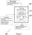
- the architecture 300 of cleaning automation block 160 consists of (i) models for membrane cleaning (RTD model), fouling state and cost model based on chemical cleaning (310) and (ii) optimizer for minimizing cleaning chemical consumption and cleaning duration (320).
- the proposed solution methodology takes into account the current fouling state of the membrane (refer eq. 7) obtained from the advanced membrane fouling monitoring solution to come up with optimal solution for chemical cleaning.
- the solution may be implemented through flow ratio control for the cleaning chemical liquor controlling the addition of chemical in the liquor based on measurement of salt concentration in the liquor.
- the cost information related to chemicals and plant down time is provided by users and available in the system as illustrated in Figure 3 . With these data, the objective function is minimized to achieve optimal values for fresh chemical addition to achieve minimal cleaning time (plant down time).
- the optimal values are used as the set point in the regulatory control (Eg ratio control) deployed for the membrane cleaning system 100.
Landscapes
- Chemical & Material Sciences (AREA)
- Engineering & Computer Science (AREA)
- Water Supply & Treatment (AREA)
- Chemical Kinetics & Catalysis (AREA)
- Life Sciences & Earth Sciences (AREA)
- Hydrology & Water Resources (AREA)
- Environmental & Geological Engineering (AREA)
- Organic Chemistry (AREA)
- Nanotechnology (AREA)
- Separation Using Semi-Permeable Membranes (AREA)
Description
- The invention related to the field of reverse osmosis separation process used for desalination and waste water reuse process. More particularly, the invention relates to a method and system for estimating the effectiveness of the membrane cleaning.
- The reverse osmosis (RO) separation process is becoming increasingly important in the last two decades for desalination and waste water reuse process. RO process is aimed at replacing the conventional energy inefficient processes namely, thermal process & chemical process. This was possible after (i) discovering low pressure and high rejection membrane at lower cost and (ii) integration of energy recovery device (ERD) for recovering energy from reject stream. Even though, membrane separation processes are proved to be energy efficient than the conventional process, the membrane separation has its own demerits such as membrane fouling (deposition of unwanted material at membrane surface due to concentration polarization) i.e. the accumulation of solute molecules near the membrane surface. These materials can be either biological or chemical in nature resulting in bio-fouling or chemical fouling, respectively. As a result, membrane separation process becomes inefficient over a period of operation due to the decrease in production flow rate because of continuous fouling at membrane surface.
- In general the RO trains are operated at recommended feed pressure and feed flow rate given by membrane operators, but in real system the optimal operating condition such as feed pressure & flow rate will be changing with respect to membrane operating condition. To overcome this issue, Membrane Performance tool is available to estimate optimal operating conditions for controling membrane fouling condition.
- Although the membranes can be operated at their optimal operating conditions, the fouling at membrane surface cannot be avoided in membrane separation process. Therefore the chemical cleaning and membrane replacement are inherent activities for all membrane separation processes. Presently the due time for membrane replacement and chemical cleaning are suggested by either membrane expert (consultant) or membrane manufactures.
- In order to minimize membrane fouling in RO process, the feed water to membrane is treated continuously with fouling control chemicals such as antiscalants. Though antiscalants dissolve the substances accumulated near the membrane surface and reduce the rate of fouling, the high dosage of antiscalants leads to increase in RO membrane degradation. Therefore, controlled addition of antiscalants to achieve controlled membrane fouling leading to minimal membrane degradation and lower chemical consumption is desired.
- Also membrane cleaning chemicals are added to clean the membrane at certain flow rate and concentration as suggested by the membrane manufacturer. Optimizing the chemical flow rate and cleaning cycle based on the current membrane fouling state will reduce the cost of chemicals. This will also help in reducing the production off time due to cleaning and hence increases the RO permeate production.
- The membrane fouling / cleaning is poorly understood due to lack of physical understanding about interaction between (i) fouling material and membrane, (ii) among fouling materials, (iii) fouling material and cleaning chemicals, and (iv) between membrane and cleaning chemicals. Since the cleaning phenomena is not well understood, the traditional practice is to keep membrane soaked in cleaning chemicals for a fixed period of time and then bring it back to operation.
- Current practice of membrane cleaning is based on recommendations from membrane manufacturers which may consume more cleaning chemicals since the recommendations are given based on feed water quality, and are not based on severity of fouling. In addition, these chemicals are also quite costly. Membrane cleaning process is not well automated and there is an ample opportunity to develop an advanced tool for estimating effectiveness of the membrane cleaning and optimizing the cleaning operation.
- The membrane cleaning chemistry and its hydrodynamics are vital in deciding the effectiveness of membrane cleaning. However, it is very difficult to represent these processes mathematically due to their complex nature. Therefore, it requires a simple alternative method to identify the effectiveness of the membrane cleaning.
-
US 6161435 discloses that the fouling state of a polymeric membrane within the high pressure housing of a spiral wound or a hollow fiber membrane module is determined. An ultra-sonic transducer positioned with its emitting face in physical engagement with the outer surface of the housing is pulse energized by a pulser/receiver device. A membrane echo signal is detected by a receiver of the pulser/receiver device. A reference echo signal indicative of a fouled or an unfouled state of the membrane is compared to the echo signal to determine the membrane fouling state. The echo to reference comparing step can be based upon comparing amplitude domain signals, comparing time-domain signals, comparing combinations of amplitude domain and time-domain signals, and comparing transformations of amplitude domain and time-domain signals. A clean or a fouled reference echo can be provided from a clean or a fouled membrane and then stored for use during a liquid separation process, or a clean reference echo signal can be obtained on-line from a second transducer whose echo signal is derived from an area of the membrane known to remain relatively unfouled during the liquid separation process, or a clean or fouled reference echo signal can be provided for later use during a cleaning process or during a liquid separation process. Multiple transducers and a switching network can sample the fouling state at different positions within the membrane module. -
WO 2009/083670 discloses an advanced control method for a membrane filtration unit, applied to the treatment of an effluent, employing microcoagulation on a membrane, which consists in injecting, upstream of the membrane, a dose of coagulation reactant(s) 30 to 80 times below the dose (X) making the zeta potential of the effluent zero, in which method: quantities defining the quality of the effluent to be treated and quantities defining the state of membrane clogging are measured as input variables; the operating point of the microcoagulation process is located on the basis of the results of the above measurements; thresholds for the input variables are determined, the microcoagulation having to be initiated when said thresholds are violated; and the coagulation reactant(s) is(are) injected depending on the results of the measurements and on the comparison of the input variables with the respective thresholds. -
WO 2008/120978 discloses a method for the filtration of a fluid was developed. The method aims to apply a certain preferred setting of one or more process parameters (e.g. a minimal concentration of coagulants) while maintaining desirable process performance by regulating the initial filtration resistance. This is achieved by a feedback controller. It was found that the method performs well; adaptation to changing conditions is achieved adequately and sufficiently fast. Applying the invention on in-line coagulation during membrane filtration has shown, that the initial resistance of the last filtration before the chemical cleaning phase can be controlled within an accuracy of approximately 3% (of the total resistance) or 9% (of the fouling resistance). Compared to the current dosing strategy, a significant reduction in coagulant consumption can be achieved. - ROTH E ET AL. "Sodium chloride stimulus-response experiments in spiral wound reverse osmosis membranes: a new method to detect fouling", DESALINATION, ELSEVIER, AMSTERDAM, NL, vol. 121, no. 2, 12 March 1999, pages 183-193, XP004222886 discloses that Fouling is generally described in terms of salt rejection and permeation flow, but these data seem to evolve very slowly, and when they reach a dramatic level, fouling is irreversible. We propose a method to determine the state of the wear of membranes by analyzing sodium chloride stimulus-response experiments. Indeed, it turns out that the shape of the distribution (RTD) of sodium chloride in the permeate flow of the membrane reveals the solute permeation mechanisms for used membranes. For new membranes the distribution of sodium chloride collected in the permeate side as well in the rejection side is unimodal. For fouled membranes we note a singular distribution form with the presence of several modes. The existence of a salt leakage peak, as well as an earlier detection of salt for all the fouled membranes, give evidence of the membrane structure modification. The intensive use of the membranes might have created an enlargement of the pore sizes; salt and solvent permeabilities are improved as well. It turns out that each permeate side sodium chloride distribution can be fitted by a weighted average of Gaussian distributions, the new membrane RTD and the shifted new membrane RTD. The coefficients of this average give us the fraction of the membrane which is enlarged, hampered by the deposited layer and not modified.
-
EP 1952879 discloses a large scale membrane separating installation wherein a cleaning chemical liquid flows to membrane units through a header and branch pipes. A cleaning chemical liquid distribution unit comprises the header and the branch pipes having a diameter smaller than that of the header. The cleaning chemical liquid distribution unit comprises a pipeline configuration uniformly distributing the cleaning chemical liquid supplied to the membrane units. - By estimating the effectiveness of the membrane cleaning, the cleaning chemical consumption and the plant down time can be minimized.
- As can be inferred from the above discussion, the membrane cleaning process is time consuming and not optimal due to excessive use of chemicals. This invention is aimed to develop a method and system for optimization of membrane cleaning process
- It is therefore an objective of the invention to optimize membrane cleaning process to provide automatic solution and cost savings by minimizing plant down time and optimal use of antiscalant cleaning chemicals for membrane cleaning. This objective is achieved by a using a method and a system according to the claims 1 and claim 6. Further preferred embodiments are evident from the dependent patent claims.
- According to the invention, a method for managing reverse osmosis membrane cleaning process in a plant performing desalination or waste water reuse by operating the reverse osmosis membrane cleaning process for a controlled time for cleaning and with a controlled value of chemical concentration in a chemical liquor prepared for cleaning the membrane, the method comprises of the steps to:
- a) Estimate fouling status of the membrane as defined in claim 1, and
- b) Determine the controlled value of chemical concentration needed in the chemical liquor and the controlled time needed for cleaning based on the fouling status of the membrane, wherein the chemical liquor is recirculated through the fouled RO membrane during the cleaning time without regular feed input.
- The value of chemical concentration and time needed for cleaning based on the fouling status of the membrane are determined using optimization techniques for cost effective and efficient operation of the plant.
- The system for reverse osmosis managing membrane cleaning process in a plant performing desalination or waste water treatment by operating the reverse osmosis membrane cleaning process for a controlled time for cleaning and with a controlled value of cleaning chemical concentration in chemical liquor prepared for cleaning the membrane is provided. The system comprises of:
- a) A membrane performance tool to obtain the membrane fouling status
- b) One or more sensors to obtain salt concentration information in the chemical liquor
- c) An automation block to administer concentration of cleaning chemical in the chemical liquor
- The membrane performance tool is based on mathematical or data model, wherein the model utilizes formulations based on physical phenomenon or/and plant parameters including statistical models for computing/estimating membrane fouling status.
- In a preferred variant of the invention, in the method for managing membrane cleaning process, the time needed for cleaning is determined using a function for concentration of salts in the chemical liquor that is obtained with Residence Time Distribution studies.
- According to the invention, in the system for managing membrane cleaning process, the automation block used to administer addition of fresh chemical to the chemical liquor has an optimizer to compute optimal value of chemicals and optimal time needed for cleaning.
- In yet another preferred variant of the invention, in the system for managing membrane cleaning process, the automation block administers addition of fresh chemical to the chemical liquor through one or more control valves controlling the flow of circulated chemical liquor and the flow of fresh chemical into the chemical liquor.
- The subject matter of the invention will be explained in more detail in the following text with reference to preferred exemplary embodiments which are illustrated in the attached drawings, in which:
-
Figure 1 schematically shows the RO membrane cleaning system; -
Figure 2 illustrates the cleaning reaction kinetics; and -
Figure 3 illustrates the architecture of the cleaning automation block - The reference symbols used in the drawings, and their meanings, are listed in summary form in the list of reference symbols. In principle, identical parts are provided with the same reference symbols in the figures.
- It should be observed that method steps and system components have been represented by conventional symbols in the figures, showing only specific details that are relevant for an understanding of the present disclosure. In the present disclosure, the method steps are used to distinguish one entity (steps) from another entity, without necessarily implying any specific order among the method steps. Further, details that may be readily apparent to person ordinarily skilled in the art may not have been disclosed and a mention of a term in singular word form (eg cleaning chemical, sensor etc) are intended to also include plurallel word form or the variety generally associated with the term in the art (eg variety/plurality of cleaning chemicals, multiple sensors used in measurement etc).
- Embodiments of the present disclosure provide a method and system for estimating effectiveness of membrance cleaning with use of estimation block and optimizing chemical comsumption to improve plant down time.
- The membrane
chemical cleaning system 100 is shown inFigure 2 . The membranechemical cleaning system 100 has aRO membrane 110 that is being cleaned with a cleaning chemical solution and various system components including cleaningchemical tank 120,valves 130, membraneperformance measurement tool 140, one ormore sensors 150 to measure chemical concentration andcleaning automation block 160 to control the process of cleaning and manage usage of the cleaning chemical. - The cleaning chemical is stored in cleaning
chemical tank 120 and it is re-circulated through the fouledRO membrane system 110. During this time there is no regular feed input to the membrane system. The output cleaning chemical from themembrane 110 is again fed to the cleaningchemical tank 120 for recirculation. The concentration of chemical will decrease due to the chemical reaction between cleaning chemical and organic/inorganic salts deposited over the membrane surface. The process temporality is represented infigure 2 . To maintain the cleaning chemical concentration in the cleaning chemical tank, additional fresh cleaning chemical is added to the system so as maintain is added to the system so as maintain favorable chemical reaction rate. The fresh chemical addition and the chemical recirculation are controlled by thecleaning automation block 160. - The concentration of cleaning chemical in membrane cleaning system is estimated from mass balance and reaction kinetic equations (1- 3) as given below


- Kinetic equation for reaction rate

- The equations for initial conditions are as follows:


- Where,
- V = Total cleaning chemical volume, m3
- Fin= Inlet cleaning chemical flow rate, m3/s
- c= Cleaning chemical concentration at membrane system, kg/m3
- cin=inlet cleaning chemical concentration, kg/m3
- Sm= membrane surface area, m2
- rc= rate of cleaning chemical reaction, kg/m2 s
- kc=reaction rate constant, (kg/m2 s) (kg/m3)-a
- a = reaction order, (-)
- cint=initial concentration of cleaning chemical, kg/m3
- Vint=initial cleaning chemical volume, m3
- The fouling state of the membrane is represented in terms of Hydrodynamic permeability (A) and Solute permeability (B). The temporal behavior of fouling in the membrane is modeled with the following equations:

- The initial condition is given by

- x = Fouling state of the membrane which could be A and B
- x ∝ = Irreversibile fouling state of the membrane which cannot be restored by chemical cleaning
- x 0 = Initial fouling state of the membrane which could be obtained from the advanced membrane fouling monitoring solution
- The
membrane performance tool 140 is either based using an ultra sound sensor to measure fouling or based on a model for fouling or any other method that provides fouling status. The model parameters may be one or more foulding parameters including hydrodynamic permeability, solute permeability, reflection coefficient etc. In addition, the model may use plant parameters such as feed pressure, reject water flow rate, product water flow rate, product water total dissolved solids for estimating fouling status (extent of fouling). The fouling status is used as an input for determining the optimal chemical usage by thecleaning automation block 160. - The cleaning automation block consists of a mathemical model that makes use of measured plant data from the plant control system or other measurement system interfaced with the cleaning automation block to provide directly measured data or data that is estimated based on one or more measured parameters related to the membrance performance or process of chemical cleaning.
- In an exemplary embodiment, the extent of fouling in membrane is estimated using the advanced membrane fouling monitoring solution in the following ways (i) by estimating the current fouling parameters from membrane model with the use of online plant measurements and (ii) by comparing the current fouling parameters with those of earlier cleaning cycles to estimate the membrane degradation right from the start of membrane operation. With this information, the approximate dosage for membrane cleaning chemicals is estimated and the fouled membrane can be initially fed with the estimated amount of chemicals.
- During the membrane cleaning process, the salts deposited over the membrane are dissolved in re-circulating liquor and its concentration is to be measured by using suitable sensors (for example sensors like ion selective electrode that measures calcium and sulphate). The model for estimation relies on data from Residence Time Distribution (RTD) studies performed for chemicals with various concentration used for cleaning of membrane and the status of fouling monitored during the studies. The probability distribution functions is thus obtained through the RTD studies. It gives the amount of time the cleaning chemical needs to be circulated in the membrane chamber for effective cleaning and it is a function of the cleaning chemical concentration in membrane chamber. The estimate of the time may be based on a suitable descriptive statistical parameter (example 85 percentile value) such as cleaning chemical concentration.
- At the begining of the process of cleaning, the concentration of the dissolved salts measured at cleaning chemical recirculation path is expected to increase in the chemical liquor as a result of chemical interaction with the fouled membrane. The chemical concentration decreases and reaches an asymptotic value at end of the cleaning. The end time is determined from the RTD data for a particular concentration of chemical and the residue in the membrane (i.e its fouling status). During the process of cleaning, fresh chemical is added in multiple steps to the circulating liquor to increase the rate of cleaning reaction and reduce the time taken for cleaning if the chemical is added in a controlled manner. Therefore, it is desired to optimally balance the addition of fresh chemical and the time for cleaning (down time for the plant) and this function is also carried out by the
cleaning automation block 160. - The goal of optimization is to minimize the cleaning chemical consumption and cleaning duration subjected to constraints such as maximum limit on chemical concentration recommended by membrane supplier.
- The objective function for optimization is

- Subjected to constraint


- Where,
- tm = membrane cleaning time as suggested by membrane manufacture, hr
- QΔt = permeate production rate in the time (t1 - tm ), m3/hr
- Cp = cost per m3 of permeate water, $
- Cc = cost per m3 of chemical, $
-

- w1, w2= weight factor
- Climit = maximum chemical concentration recommended by membrane supplier (used as constraint).
- (t1 - tm) is always maintained as a positive number i.e. absolute number is taken in for the calculations.
- The control strategy is formulated with the optimization objective to find the optimal profiles for cleaning chemical flux and its concentration as a function of time, while minimizing the cleaning cost and cleaning time. As shown in
Figure 3 , thearchitecture 300 ofcleaning automation block 160 consists of (i) models for membrane cleaning (RTD model), fouling state and cost model based on chemical cleaning (310) and (ii) optimizer for minimizing cleaning chemical consumption and cleaning duration (320). The proposed solution methodology takes into account the current fouling state of the membrane (refer eq. 7) obtained from the advanced membrane fouling monitoring solution to come up with optimal solution for chemical cleaning. The solution may be implemented through flow ratio control for the cleaning chemical liquor controlling the addition of chemical in the liquor based on measurement of salt concentration in the liquor. - The salt concentration data, fouling status data from the components as described above for the
membrance cleaning system 100 and also has information about cost of chemicals, cost of plant down time where the cleaning time and fresh chemical addition is estimated from the RTD model present with thecleaning automation block 160. The cost information related to chemicals and plant down time is provided by users and available in the system as illustrated inFigure 3 . With these data, the objective function is minimized to achieve optimal values for fresh chemical addition to achieve minimal cleaning time (plant down time). The optimal values are used as the set point in the regulatory control (Eg ratio control) deployed for themembrane cleaning system 100.
Claims (7)
- A method for managing reverse osmosis (RO) membrane cleaning process in a plant performing desalination or waste water reuse by operating the reverse osmosis membrane cleaning process for a controlled time for cleaning and with a controlled value of chemical concentration in a chemical liquor prepared for cleaning a RO membrane, the method comprising of:a) Estimating fouling status of the RO membrane, wherein estimating the fouling status of the RO membrane is performed using a mathematical or data model based on physical phenomenon or/and plant parameters; andb) Determining the controlled value of chemical concentration and the controlled time needed for cleaning based on the fouling status of the RO membrane, wherein the value of chemicals concentration and time needed for cleaning based on the fouling status of the RO membrane are determined using optimization techniques for cost effective and efficient operation of the plant;wherein the chemical liquor is recirculated through the fouled RO membrane during the cleaning time without regular feed input.
- The method for managing membrane cleaning process as claimed in Claim 1, wherein the controlled value of chemical concentration is administered to provide optimal use of chemicals and optimal time needed for cleaning.
- The method for managing membrane cleaning process as claimed in Claim 2, wherein the optimization is performed considering the cost of chemicals or/and cost related to production loss during plant down time.
- The method for managing membrane cleaning process as claimed in Claim 1, wherein the controlled time needed for cleaning is determined using a function for concentration of salts in the chemical liquor.
- The method for managing membrane cleaning process as claimed in Claim 4, wherein the function for concentration of salts in the chemical liquor is obtained with Residence Time Distribution studies.
- A system (100) for managing reverse osmosis (RO) membrane cleaning process in a plant performing desalination or waste water treatment by operating a RO membrane cleaning process for a controlled time for cleaning and with a controlled value of cleaning chemical concentration in chemical liquor prepared for cleaning the RO membrane (110), the system (100) comprising of:a. A membrane performance tool (140) to obtain the RO membrane fouling status using a mathematical or data model based on physical phenomenon or/and plant parameters;b. One or more sensors (150) to obtain salt concentration information in the chemical liquor; andc. An automation block (160) to administer concentration of cleaning chemical in the chemical liquor, wherein the automation block (160) to administer addition of fresh cleaning chemicals to the chemical liquor has an optimizer to compute optimal value of cleaning chemical concentration and optimal time needed for cleaning; andis adapted to recirculate the chemical liquor through the fouled RO membrane (110) during the cleaning time without regular feed input.
- The system (100) for managing membrane cleaning process as claimed in Claim 6, wherein the automation block (160) administers addition of fresh chemical to the chemical liquor through one or more control valves (130) controlling the flow of circulated chemical liquor and the flow of fresh chemical into the chemical liquor.
Applications Claiming Priority (2)
| Application Number | Priority Date | Filing Date | Title |
|---|---|---|---|
| IN1087CH2010 | 2010-04-19 | ||
| PCT/IB2010/002472 WO2011132016A1 (en) | 2010-04-19 | 2010-09-30 | A method and system for optimizing membrane cleaning process |
Publications (3)
| Publication Number | Publication Date |
|---|---|
| EP2560743A1 EP2560743A1 (en) | 2013-02-27 |
| EP2560743B1 true EP2560743B1 (en) | 2019-07-17 |
| EP2560743B8 EP2560743B8 (en) | 2019-09-11 |
Family
ID=43432126
Family Applications (1)
| Application Number | Title | Priority Date | Filing Date |
|---|---|---|---|
| EP10768807.9A Active EP2560743B8 (en) | 2010-04-19 | 2010-09-30 | A method and system for an optimized membrane cleaning process |
Country Status (10)
| Country | Link |
|---|---|
| US (1) | US8918217B2 (en) |
| EP (1) | EP2560743B8 (en) |
| CN (1) | CN102985170B (en) |
| AU (1) | AU2010351847B2 (en) |
| CL (1) | CL2012002940A1 (en) |
| ES (1) | ES2750273T3 (en) |
| IL (1) | IL222555A (en) |
| MX (1) | MX2012012185A (en) |
| SG (1) | SG184913A1 (en) |
| WO (1) | WO2011132016A1 (en) |
Families Citing this family (16)
| Publication number | Priority date | Publication date | Assignee | Title |
|---|---|---|---|---|
| CN103347594B (en) * | 2010-11-26 | 2016-02-10 | Abb研究有限公司 | Method and system for controlling fouling in membrane system operations |
| AU2011363440A1 (en) * | 2011-03-21 | 2013-10-31 | Abb Research Ltd | Method and system for minimizing energy consumption during reverse osmosis unit operation |
| DE102011114912B8 (en) * | 2011-09-24 | 2018-10-11 | Vivonic Gmbh | Device for producing ultrapure water |
| JP5798908B2 (en) * | 2011-12-19 | 2015-10-21 | 株式会社日立製作所 | Reverse osmosis treatment device and cleaning method for reverse osmosis treatment device |
| SG11201403845TA (en) * | 2011-12-23 | 2014-10-30 | Abb Technology Ltd | A method and a system for monitoring and control of fouling and and optimization thereof of two side membrane fouling process |
| CN103638817B (en) * | 2013-11-19 | 2015-12-09 | 长沙中联重科环卫机械有限公司 | Membrane column cleaning control method, device, system and sewage treatment equipment |
| CN104250034B (en) * | 2014-03-24 | 2017-01-04 | 杭州电子科技大学 | A kind of whole process rolling reverse osmosis seawater desalination system operation optimization method |
| BR112017002862B1 (en) * | 2014-08-12 | 2022-08-16 | Water Planet, Inc | METHODS FOR FILTERING FLUID, SYSTEM, APPLIANCE AND COMPUTER-READABLE NON-TRANSITORY STORAGE MEDIA |
| CN105214505B (en) * | 2015-11-13 | 2016-07-06 | 北京金泽环境能源技术研究有限公司 | The in-site chemical cleaning method and system of hyperfiltration/microfiltration film |
| JP6732322B2 (en) * | 2017-09-20 | 2020-07-29 | Wota株式会社 | Information processing equipment |
| WO2020158895A1 (en) * | 2019-01-31 | 2020-08-06 | 旭化成株式会社 | Method for determining cleaning conditions of filter |
| EP4157495A4 (en) | 2020-06-02 | 2024-09-18 | Synauta Inc. | APPARATUS AND METHODS FOR CLEANING REVERSE OSMOSIS SYSTEMS |
| EP4208870A4 (en) | 2020-09-04 | 2024-11-06 | Buckman Laboratories International, Inc. | Predictive systems and methods for proactive intervention in chemical processes |
| CN115970499A (en) * | 2023-03-20 | 2023-04-18 | 金科环境股份有限公司 | Reverse osmosis system control method and device, electronic equipment and storage medium |
| CN117534180A (en) * | 2023-11-15 | 2024-02-09 | 苏州科索膜技术有限公司 | Intelligent maintenance system and method for membrane separation component |
| CN118718740B (en) * | 2024-09-04 | 2024-11-05 | 四川兴澳环境技术服务有限公司 | Reverse osmosis system cleaning operation control method, device, equipment and storage medium |
Citations (1)
| Publication number | Priority date | Publication date | Assignee | Title |
|---|---|---|---|---|
| EP1952879A1 (en) * | 2005-10-24 | 2008-08-06 | Kubota Corporation | Large scale membrane separating device |
Family Cites Families (6)
| Publication number | Priority date | Publication date | Assignee | Title |
|---|---|---|---|---|
| US5393502A (en) * | 1993-09-07 | 1995-02-28 | International Purification Systems, Inc. | Solubilizing apparatus |
| ES2331809T3 (en) * | 1995-03-15 | 2010-01-15 | Siemens Water Technologies Corp. | FILTRATION CONTROL AND MONITORING SYSTEM. |
| AU5221099A (en) * | 1998-07-21 | 2000-02-14 | University Technology Corporation | Method and apparatus for determining the state of fouling/cleaning of membrane modules |
| US20080099399A1 (en) * | 2006-10-27 | 2008-05-01 | Its Engineered Systems, Inc. | Filtration system |
| NL2000586C2 (en) * | 2007-03-30 | 2008-10-02 | Norit Procestechnologie B V | Method for filtering a fluid. |
| FR2922466B1 (en) * | 2007-10-19 | 2010-06-25 | Degremont | METHOD FOR ADVANCED MANAGEMENT OF A MEMBRANE FILTRATION UNIT, AND SYSTEM FOR IMPLEMENTING THE METHOD |
-
2010
- 2010-09-30 MX MX2012012185A patent/MX2012012185A/en active IP Right Grant
- 2010-09-30 SG SG2012077244A patent/SG184913A1/en unknown
- 2010-09-30 ES ES10768807T patent/ES2750273T3/en active Active
- 2010-09-30 WO PCT/IB2010/002472 patent/WO2011132016A1/en not_active Ceased
- 2010-09-30 AU AU2010351847A patent/AU2010351847B2/en not_active Ceased
- 2010-09-30 EP EP10768807.9A patent/EP2560743B8/en active Active
- 2010-09-30 CN CN201080066316.0A patent/CN102985170B/en active Active
-
2012
- 2012-10-18 US US13/655,021 patent/US8918217B2/en active Active
- 2012-10-18 IL IL222555A patent/IL222555A/en active IP Right Grant
- 2012-10-19 CL CL2012002940A patent/CL2012002940A1/en unknown
Patent Citations (1)
| Publication number | Priority date | Publication date | Assignee | Title |
|---|---|---|---|---|
| EP1952879A1 (en) * | 2005-10-24 | 2008-08-06 | Kubota Corporation | Large scale membrane separating device |
Also Published As
| Publication number | Publication date |
|---|---|
| WO2011132016A1 (en) | 2011-10-27 |
| WO2011132016A9 (en) | 2013-01-17 |
| EP2560743A1 (en) | 2013-02-27 |
| CN102985170A (en) | 2013-03-20 |
| MX2012012185A (en) | 2012-12-17 |
| EP2560743B8 (en) | 2019-09-11 |
| CL2012002940A1 (en) | 2013-05-24 |
| SG184913A1 (en) | 2012-11-29 |
| US8918217B2 (en) | 2014-12-23 |
| AU2010351847B2 (en) | 2014-09-04 |
| AU2010351847A1 (en) | 2012-11-08 |
| US20130060384A1 (en) | 2013-03-07 |
| ES2750273T3 (en) | 2020-03-25 |
| IL222555A (en) | 2017-01-31 |
| CN102985170B (en) | 2015-10-21 |
Similar Documents
| Publication | Publication Date | Title |
|---|---|---|
| US8918217B2 (en) | Method and system for optimizing membrane cleaning process | |
| US11401172B2 (en) | Intelligent fluid filtration management system | |
| Ferrero et al. | Automatic control systems for submerged membrane bioreactors: A state-of-the-art review | |
| JP6189835B2 (en) | How to maintain process stream water quality | |
| US6077435A (en) | Filtration monitoring and control system | |
| KR101133664B1 (en) | Prediction, evaluation and control method of chemical cleaning of membrane process using genetic algorithm and programming in water treatment system | |
| EP1300186A1 (en) | Filtration monitoring and control system | |
| CN102015076A (en) | Online Performance Management of Membrane Separation Processes | |
| WO2008132186A1 (en) | Supervisory control system and method for membrane cleaning | |
| WO2012173988A1 (en) | Control system for wastewater treatment plants with membrane bioreactors | |
| KR20130085220A (en) | Monitoring method real-time fouling potential in reverse osmosis process for seawater desalination and desalination equipment having such monitoring function | |
| US10821404B2 (en) | Control method for a filter system | |
| KR101612230B1 (en) | Device for continuously measuring FI and method for measuring FI | |
| JPH11319516A (en) | Water filtration apparatus and method of operating the same | |
| US20100032373A1 (en) | Method for the optimised management of a membrane filtration unit and equipment for realising the same | |
| KR101533554B1 (en) | A assembly and method of real-time fouling monitoring in reverse osmosis membrane vessel | |
| KR101612231B1 (en) | A assembly and method for cleaning diagnosis in reverse osmosis membrane vessel | |
| JP3311158B2 (en) | Operation control device for desalination plant | |
| KR101277199B1 (en) | Pretreatment apparatus and method for seawater desalination | |
| CN105921017A (en) | Online performance management of membrane separation process | |
| JP7000063B2 (en) | Cleaning air volume control device and cleaning air volume control method | |
| Janus et al. | A behavioural membrane fouling model for integrated simulation of membrane bioreactors for wastewater treatment | |
| JP2015231607A (en) | Remote management control system for membrane filtration apparatus | |
| CN114259874A (en) | An automatic control system for reverse osmosis water treatment | |
| JP2026014505A (en) | Membrane filtration equipment operation support system, membrane filtration equipment control device, membrane filtration equipment control method, and computer program |
Legal Events
| Date | Code | Title | Description |
|---|---|---|---|
| PUAI | Public reference made under article 153(3) epc to a published international application that has entered the european phase |
Free format text: ORIGINAL CODE: 0009012 |
|
| 17P | Request for examination filed |
Effective date: 20121119 |
|
| AK | Designated contracting states |
Kind code of ref document: A1 Designated state(s): AL AT BE BG CH CY CZ DE DK EE ES FI FR GB GR HR HU IE IS IT LI LT LU LV MC MK MT NL NO PL PT RO SE SI SK SM TR |
|
| DAX | Request for extension of the european patent (deleted) | ||
| STAA | Information on the status of an ep patent application or granted ep patent |
Free format text: STATUS: EXAMINATION IS IN PROGRESS |
|
| 17Q | First examination report despatched |
Effective date: 20180723 |
|
| GRAP | Despatch of communication of intention to grant a patent |
Free format text: ORIGINAL CODE: EPIDOSNIGR1 |
|
| STAA | Information on the status of an ep patent application or granted ep patent |
Free format text: STATUS: GRANT OF PATENT IS INTENDED |
|
| INTG | Intention to grant announced |
Effective date: 20190123 |
|
| GRAS | Grant fee paid |
Free format text: ORIGINAL CODE: EPIDOSNIGR3 |
|
| GRAA | (expected) grant |
Free format text: ORIGINAL CODE: 0009210 |
|
| STAA | Information on the status of an ep patent application or granted ep patent |
Free format text: STATUS: THE PATENT HAS BEEN GRANTED |
|
| AK | Designated contracting states |
Kind code of ref document: B1 Designated state(s): AL AT BE BG CH CY CZ DE DK EE ES FI FR GB GR HR HU IE IS IT LI LT LU LV MC MK MT NL NO PL PT RO SE SI SK SM TR |
|
| REG | Reference to a national code |
Ref country code: GB Ref legal event code: FG4D |
|
| REG | Reference to a national code |
Ref country code: CH Ref legal event code: EP |
|
| REG | Reference to a national code |
Ref country code: IE Ref legal event code: FG4D |
|
| REG | Reference to a national code |
Ref country code: DE Ref legal event code: R096 Ref document number: 602010060051 Country of ref document: DE |
|
| REG | Reference to a national code |
Ref country code: CH Ref legal event code: PK Free format text: BERICHTIGUNG B8 Ref country code: AT Ref legal event code: REF Ref document number: 1155327 Country of ref document: AT Kind code of ref document: T Effective date: 20190815 |
|
| RAP2 | Party data changed (patent owner data changed or rights of a patent transferred) |
Owner name: ABB SCHWEIZ AG |
|
| REG | Reference to a national code |
Ref country code: NL Ref legal event code: MP Effective date: 20190717 |
|
| REG | Reference to a national code |
Ref country code: LT Ref legal event code: MG4D |
|
| REG | Reference to a national code |
Ref country code: AT Ref legal event code: MK05 Ref document number: 1155327 Country of ref document: AT Kind code of ref document: T Effective date: 20190717 |
|
| PG25 | Lapsed in a contracting state [announced via postgrant information from national office to epo] |
Ref country code: LT Free format text: LAPSE BECAUSE OF FAILURE TO SUBMIT A TRANSLATION OF THE DESCRIPTION OR TO PAY THE FEE WITHIN THE PRESCRIBED TIME-LIMIT Effective date: 20190717 Ref country code: NL Free format text: LAPSE BECAUSE OF FAILURE TO SUBMIT A TRANSLATION OF THE DESCRIPTION OR TO PAY THE FEE WITHIN THE PRESCRIBED TIME-LIMIT Effective date: 20190717 Ref country code: AT Free format text: LAPSE BECAUSE OF FAILURE TO SUBMIT A TRANSLATION OF THE DESCRIPTION OR TO PAY THE FEE WITHIN THE PRESCRIBED TIME-LIMIT Effective date: 20190717 Ref country code: PT Free format text: LAPSE BECAUSE OF FAILURE TO SUBMIT A TRANSLATION OF THE DESCRIPTION OR TO PAY THE FEE WITHIN THE PRESCRIBED TIME-LIMIT Effective date: 20191118 Ref country code: SE Free format text: LAPSE BECAUSE OF FAILURE TO SUBMIT A TRANSLATION OF THE DESCRIPTION OR TO PAY THE FEE WITHIN THE PRESCRIBED TIME-LIMIT Effective date: 20190717 Ref country code: BG Free format text: LAPSE BECAUSE OF FAILURE TO SUBMIT A TRANSLATION OF THE DESCRIPTION OR TO PAY THE FEE WITHIN THE PRESCRIBED TIME-LIMIT Effective date: 20191017 Ref country code: HR Free format text: LAPSE BECAUSE OF FAILURE TO SUBMIT A TRANSLATION OF THE DESCRIPTION OR TO PAY THE FEE WITHIN THE PRESCRIBED TIME-LIMIT Effective date: 20190717 Ref country code: NO Free format text: LAPSE BECAUSE OF FAILURE TO SUBMIT A TRANSLATION OF THE DESCRIPTION OR TO PAY THE FEE WITHIN THE PRESCRIBED TIME-LIMIT Effective date: 20191017 Ref country code: FI Free format text: LAPSE BECAUSE OF FAILURE TO SUBMIT A TRANSLATION OF THE DESCRIPTION OR TO PAY THE FEE WITHIN THE PRESCRIBED TIME-LIMIT Effective date: 20190717 |
|
| REG | Reference to a national code |
Ref country code: DE Ref legal event code: R082 Ref document number: 602010060051 Country of ref document: DE Representative=s name: ZIMMERMANN & PARTNER PATENTANWAELTE MBB, DE |
|
| PG25 | Lapsed in a contracting state [announced via postgrant information from national office to epo] |
Ref country code: GR Free format text: LAPSE BECAUSE OF FAILURE TO SUBMIT A TRANSLATION OF THE DESCRIPTION OR TO PAY THE FEE WITHIN THE PRESCRIBED TIME-LIMIT Effective date: 20191018 Ref country code: IS Free format text: LAPSE BECAUSE OF FAILURE TO SUBMIT A TRANSLATION OF THE DESCRIPTION OR TO PAY THE FEE WITHIN THE PRESCRIBED TIME-LIMIT Effective date: 20191117 Ref country code: AL Free format text: LAPSE BECAUSE OF FAILURE TO SUBMIT A TRANSLATION OF THE DESCRIPTION OR TO PAY THE FEE WITHIN THE PRESCRIBED TIME-LIMIT Effective date: 20190717 Ref country code: LV Free format text: LAPSE BECAUSE OF FAILURE TO SUBMIT A TRANSLATION OF THE DESCRIPTION OR TO PAY THE FEE WITHIN THE PRESCRIBED TIME-LIMIT Effective date: 20190717 |
|
| REG | Reference to a national code |
Ref country code: ES Ref legal event code: FG2A Ref document number: 2750273 Country of ref document: ES Kind code of ref document: T3 Effective date: 20200325 |
|
| PG25 | Lapsed in a contracting state [announced via postgrant information from national office to epo] |
Ref country code: TR Free format text: LAPSE BECAUSE OF FAILURE TO SUBMIT A TRANSLATION OF THE DESCRIPTION OR TO PAY THE FEE WITHIN THE PRESCRIBED TIME-LIMIT Effective date: 20190717 |
|
| PG25 | Lapsed in a contracting state [announced via postgrant information from national office to epo] |
Ref country code: RO Free format text: LAPSE BECAUSE OF FAILURE TO SUBMIT A TRANSLATION OF THE DESCRIPTION OR TO PAY THE FEE WITHIN THE PRESCRIBED TIME-LIMIT Effective date: 20190717 Ref country code: DK Free format text: LAPSE BECAUSE OF FAILURE TO SUBMIT A TRANSLATION OF THE DESCRIPTION OR TO PAY THE FEE WITHIN THE PRESCRIBED TIME-LIMIT Effective date: 20190717 Ref country code: IT Free format text: LAPSE BECAUSE OF FAILURE TO SUBMIT A TRANSLATION OF THE DESCRIPTION OR TO PAY THE FEE WITHIN THE PRESCRIBED TIME-LIMIT Effective date: 20190717 Ref country code: EE Free format text: LAPSE BECAUSE OF FAILURE TO SUBMIT A TRANSLATION OF THE DESCRIPTION OR TO PAY THE FEE WITHIN THE PRESCRIBED TIME-LIMIT Effective date: 20190717 Ref country code: PL Free format text: LAPSE BECAUSE OF FAILURE TO SUBMIT A TRANSLATION OF THE DESCRIPTION OR TO PAY THE FEE WITHIN THE PRESCRIBED TIME-LIMIT Effective date: 20190717 |
|
| PG25 | Lapsed in a contracting state [announced via postgrant information from national office to epo] |
Ref country code: CZ Free format text: LAPSE BECAUSE OF FAILURE TO SUBMIT A TRANSLATION OF THE DESCRIPTION OR TO PAY THE FEE WITHIN THE PRESCRIBED TIME-LIMIT Effective date: 20190717 Ref country code: SK Free format text: LAPSE BECAUSE OF FAILURE TO SUBMIT A TRANSLATION OF THE DESCRIPTION OR TO PAY THE FEE WITHIN THE PRESCRIBED TIME-LIMIT Effective date: 20190717 Ref country code: MC Free format text: LAPSE BECAUSE OF FAILURE TO SUBMIT A TRANSLATION OF THE DESCRIPTION OR TO PAY THE FEE WITHIN THE PRESCRIBED TIME-LIMIT Effective date: 20190717 Ref country code: SM Free format text: LAPSE BECAUSE OF FAILURE TO SUBMIT A TRANSLATION OF THE DESCRIPTION OR TO PAY THE FEE WITHIN THE PRESCRIBED TIME-LIMIT Effective date: 20190717 Ref country code: IS Free format text: LAPSE BECAUSE OF FAILURE TO SUBMIT A TRANSLATION OF THE DESCRIPTION OR TO PAY THE FEE WITHIN THE PRESCRIBED TIME-LIMIT Effective date: 20200224 |
|
| REG | Reference to a national code |
Ref country code: CH Ref legal event code: PL |
|
| REG | Reference to a national code |
Ref country code: DE Ref legal event code: R097 Ref document number: 602010060051 Country of ref document: DE |
|
| PLBE | No opposition filed within time limit |
Free format text: ORIGINAL CODE: 0009261 |
|
| STAA | Information on the status of an ep patent application or granted ep patent |
Free format text: STATUS: NO OPPOSITION FILED WITHIN TIME LIMIT |
|
| PG2D | Information on lapse in contracting state deleted |
Ref country code: IS |
|
| PG25 | Lapsed in a contracting state [announced via postgrant information from national office to epo] |
Ref country code: IE Free format text: LAPSE BECAUSE OF NON-PAYMENT OF DUE FEES Effective date: 20190930 Ref country code: LU Free format text: LAPSE BECAUSE OF NON-PAYMENT OF DUE FEES Effective date: 20190930 Ref country code: CH Free format text: LAPSE BECAUSE OF NON-PAYMENT OF DUE FEES Effective date: 20190930 Ref country code: LI Free format text: LAPSE BECAUSE OF NON-PAYMENT OF DUE FEES Effective date: 20190930 |
|
| REG | Reference to a national code |
Ref country code: BE Ref legal event code: MM Effective date: 20190930 |
|
| 26N | No opposition filed |
Effective date: 20200603 |
|
| PG25 | Lapsed in a contracting state [announced via postgrant information from national office to epo] |
Ref country code: SI Free format text: LAPSE BECAUSE OF FAILURE TO SUBMIT A TRANSLATION OF THE DESCRIPTION OR TO PAY THE FEE WITHIN THE PRESCRIBED TIME-LIMIT Effective date: 20190717 Ref country code: BE Free format text: LAPSE BECAUSE OF NON-PAYMENT OF DUE FEES Effective date: 20190930 |
|
| GBPC | Gb: european patent ceased through non-payment of renewal fee |
Effective date: 20191017 |
|
| PG25 | Lapsed in a contracting state [announced via postgrant information from national office to epo] |
Ref country code: GB Free format text: LAPSE BECAUSE OF NON-PAYMENT OF DUE FEES Effective date: 20191017 Ref country code: FR Free format text: LAPSE BECAUSE OF NON-PAYMENT OF DUE FEES Effective date: 20190930 |
|
| PG25 | Lapsed in a contracting state [announced via postgrant information from national office to epo] |
Ref country code: CY Free format text: LAPSE BECAUSE OF FAILURE TO SUBMIT A TRANSLATION OF THE DESCRIPTION OR TO PAY THE FEE WITHIN THE PRESCRIBED TIME-LIMIT Effective date: 20190717 |
|
| PG25 | Lapsed in a contracting state [announced via postgrant information from national office to epo] |
Ref country code: MT Free format text: LAPSE BECAUSE OF FAILURE TO SUBMIT A TRANSLATION OF THE DESCRIPTION OR TO PAY THE FEE WITHIN THE PRESCRIBED TIME-LIMIT Effective date: 20190717 Ref country code: HU Free format text: LAPSE BECAUSE OF FAILURE TO SUBMIT A TRANSLATION OF THE DESCRIPTION OR TO PAY THE FEE WITHIN THE PRESCRIBED TIME-LIMIT; INVALID AB INITIO Effective date: 20100930 |
|
| PG25 | Lapsed in a contracting state [announced via postgrant information from national office to epo] |
Ref country code: MK Free format text: LAPSE BECAUSE OF FAILURE TO SUBMIT A TRANSLATION OF THE DESCRIPTION OR TO PAY THE FEE WITHIN THE PRESCRIBED TIME-LIMIT Effective date: 20190717 |
|
| PGFP | Annual fee paid to national office [announced via postgrant information from national office to epo] |
Ref country code: DE Payment date: 20240918 Year of fee payment: 15 |
|
| PGFP | Annual fee paid to national office [announced via postgrant information from national office to epo] |
Ref country code: ES Payment date: 20241025 Year of fee payment: 15 |