EP2559835A1 - Door opening/closing apparatus - Google Patents
Door opening/closing apparatus Download PDFInfo
- Publication number
- EP2559835A1 EP2559835A1 EP11768675A EP11768675A EP2559835A1 EP 2559835 A1 EP2559835 A1 EP 2559835A1 EP 11768675 A EP11768675 A EP 11768675A EP 11768675 A EP11768675 A EP 11768675A EP 2559835 A1 EP2559835 A1 EP 2559835A1
- Authority
- EP
- European Patent Office
- Prior art keywords
- door
- arm
- slider
- opening
- closing device
- Prior art date
- Legal status (The legal status is an assumption and is not a legal conclusion. Google has not performed a legal analysis and makes no representation as to the accuracy of the status listed.)
- Withdrawn
Links
- 238000013016 damping Methods 0.000 claims abstract description 27
- 238000003780 insertion Methods 0.000 claims description 5
- 230000037431 insertion Effects 0.000 claims description 5
- 238000006073 displacement reaction Methods 0.000 abstract description 3
- 230000006835 compression Effects 0.000 description 13
- 238000007906 compression Methods 0.000 description 13
- 238000000034 method Methods 0.000 description 5
- 239000011347 resin Substances 0.000 description 3
- 229920005989 resin Polymers 0.000 description 3
- 239000002184 metal Substances 0.000 description 2
- 238000000465 moulding Methods 0.000 description 2
- 230000007935 neutral effect Effects 0.000 description 2
- 230000002787 reinforcement Effects 0.000 description 2
- 230000002238 attenuated effect Effects 0.000 description 1
- 230000000694 effects Effects 0.000 description 1
- 239000012530 fluid Substances 0.000 description 1
Images


Classifications
-
- E—FIXED CONSTRUCTIONS
- E05—LOCKS; KEYS; WINDOW OR DOOR FITTINGS; SAFES
- E05D—HINGES OR SUSPENSION DEVICES FOR DOORS, WINDOWS OR WINGS
- E05D3/00—Hinges with pins
- E05D3/06—Hinges with pins with two or more pins
- E05D3/14—Hinges with pins with two or more pins with four parallel pins and two arms
-
- E—FIXED CONSTRUCTIONS
- E05—LOCKS; KEYS; WINDOW OR DOOR FITTINGS; SAFES
- E05D—HINGES OR SUSPENSION DEVICES FOR DOORS, WINDOWS OR WINGS
- E05D15/00—Suspension arrangements for wings
- E05D15/40—Suspension arrangements for wings supported on arms movable in vertical planes
- E05D15/46—Suspension arrangements for wings supported on arms movable in vertical planes with two pairs of pivoted arms
-
- E—FIXED CONSTRUCTIONS
- E05—LOCKS; KEYS; WINDOW OR DOOR FITTINGS; SAFES
- E05F—DEVICES FOR MOVING WINGS INTO OPEN OR CLOSED POSITION; CHECKS FOR WINGS; WING FITTINGS NOT OTHERWISE PROVIDED FOR, CONCERNED WITH THE FUNCTIONING OF THE WING
- E05F1/00—Closers or openers for wings, not otherwise provided for in this subclass
- E05F1/08—Closers or openers for wings, not otherwise provided for in this subclass spring-actuated, e.g. for horizontally sliding wings
- E05F1/10—Closers or openers for wings, not otherwise provided for in this subclass spring-actuated, e.g. for horizontally sliding wings for swinging wings, e.g. counterbalance
- E05F1/12—Mechanisms in the shape of hinges or pivots, operated by springs
- E05F1/1246—Mechanisms in the shape of hinges or pivots, operated by springs with a coil spring perpendicular to the pivot axis
- E05F1/1253—Mechanisms in the shape of hinges or pivots, operated by springs with a coil spring perpendicular to the pivot axis with a compression spring
- E05F1/1261—Mechanisms in the shape of hinges or pivots, operated by springs with a coil spring perpendicular to the pivot axis with a compression spring for counterbalancing
-
- E—FIXED CONSTRUCTIONS
- E05—LOCKS; KEYS; WINDOW OR DOOR FITTINGS; SAFES
- E05F—DEVICES FOR MOVING WINGS INTO OPEN OR CLOSED POSITION; CHECKS FOR WINGS; WING FITTINGS NOT OTHERWISE PROVIDED FOR, CONCERNED WITH THE FUNCTIONING OF THE WING
- E05F5/00—Braking devices, e.g. checks; Stops; Buffers
-
- E—FIXED CONSTRUCTIONS
- E05—LOCKS; KEYS; WINDOW OR DOOR FITTINGS; SAFES
- E05F—DEVICES FOR MOVING WINGS INTO OPEN OR CLOSED POSITION; CHECKS FOR WINGS; WING FITTINGS NOT OTHERWISE PROVIDED FOR, CONCERNED WITH THE FUNCTIONING OF THE WING
- E05F5/00—Braking devices, e.g. checks; Stops; Buffers
- E05F5/02—Braking devices, e.g. checks; Stops; Buffers specially for preventing the slamming of swinging wings during final closing movement, e.g. jamb stops
- E05F5/027—Braking devices, e.g. checks; Stops; Buffers specially for preventing the slamming of swinging wings during final closing movement, e.g. jamb stops with closing action
-
- E—FIXED CONSTRUCTIONS
- E05—LOCKS; KEYS; WINDOW OR DOOR FITTINGS; SAFES
- E05F—DEVICES FOR MOVING WINGS INTO OPEN OR CLOSED POSITION; CHECKS FOR WINGS; WING FITTINGS NOT OTHERWISE PROVIDED FOR, CONCERNED WITH THE FUNCTIONING OF THE WING
- E05F5/00—Braking devices, e.g. checks; Stops; Buffers
- E05F5/06—Buffers or stops limiting opening of swinging wings, e.g. floor or wall stops
- E05F5/10—Buffers or stops limiting opening of swinging wings, e.g. floor or wall stops with piston brakes
-
- E—FIXED CONSTRUCTIONS
- E05—LOCKS; KEYS; WINDOW OR DOOR FITTINGS; SAFES
- E05Y—INDEXING SCHEME ASSOCIATED WITH SUBCLASSES E05D AND E05F, RELATING TO CONSTRUCTION ELEMENTS, ELECTRIC CONTROL, POWER SUPPLY, POWER SIGNAL OR TRANSMISSION, USER INTERFACES, MOUNTING OR COUPLING, DETAILS, ACCESSORIES, AUXILIARY OPERATIONS NOT OTHERWISE PROVIDED FOR, APPLICATION THEREOF
- E05Y2201/00—Constructional elements; Accessories therefor
- E05Y2201/20—Brakes; Disengaging means; Holders; Stops; Valves; Accessories therefor
- E05Y2201/252—Type of friction
- E05Y2201/26—Mechanical friction
-
- E—FIXED CONSTRUCTIONS
- E05—LOCKS; KEYS; WINDOW OR DOOR FITTINGS; SAFES
- E05Y—INDEXING SCHEME ASSOCIATED WITH SUBCLASSES E05D AND E05F, RELATING TO CONSTRUCTION ELEMENTS, ELECTRIC CONTROL, POWER SUPPLY, POWER SIGNAL OR TRANSMISSION, USER INTERFACES, MOUNTING OR COUPLING, DETAILS, ACCESSORIES, AUXILIARY OPERATIONS NOT OTHERWISE PROVIDED FOR, APPLICATION THEREOF
- E05Y2201/00—Constructional elements; Accessories therefor
- E05Y2201/20—Brakes; Disengaging means; Holders; Stops; Valves; Accessories therefor
- E05Y2201/262—Type of motion, e.g. braking
- E05Y2201/264—Type of motion, e.g. braking linear
-
- E—FIXED CONSTRUCTIONS
- E05—LOCKS; KEYS; WINDOW OR DOOR FITTINGS; SAFES
- E05Y—INDEXING SCHEME ASSOCIATED WITH SUBCLASSES E05D AND E05F, RELATING TO CONSTRUCTION ELEMENTS, ELECTRIC CONTROL, POWER SUPPLY, POWER SIGNAL OR TRANSMISSION, USER INTERFACES, MOUNTING OR COUPLING, DETAILS, ACCESSORIES, AUXILIARY OPERATIONS NOT OTHERWISE PROVIDED FOR, APPLICATION THEREOF
- E05Y2900/00—Application of doors, windows, wings or fittings thereof
- E05Y2900/20—Application of doors, windows, wings or fittings thereof for furniture, e.g. cabinets
Definitions
- the present invention relates to a door opening and closing device, provided between a door and a door mounting member such as a cabinet, for enabling smooth opening and closing operations of the door.
- the door opening and closing device mounted on the door has the function of enabling the manual opening operation of the door easily and by a small force with use of a biasing force of a compression spring and the function of slowing the opening and closing operations of the door by a damping force of a damper (see PL1).
- Such a door opening and closing device has an arm which rotates by opening and closing operations of the door and a runner that is biased by a compression spring to give a biasing force in the opening or closing direction to the arm.
- the arm and the runner are connected to each other by a link arm which synchronizes rotation of the arm with linear movement of the runner.
- An end of the link arm is rotatably connected to the runner and the other end of the link arm is rotatably connected to the periphery of the rotation center of the arm.
- the door opening and closing device is provided with a damper for slowing the opening and closing operations of the door.
- the damper is used to brake the opening or closing operation of the door based on the elastic force of the compression spring, the door can open and close slowly.
- the patent literature 1 discloses a door opening and closing device in which a rotary damper is used as the above-mentioned damper and is mounted on the rotation axis of the arm.
- a one-way clutch may be built in the rotary damper thereby to generate a damping force only in opening or closing of the door.
- the patent literature 2 discloses an example of using a linear damper. There is provided a neutral range between the opening position and the closing position of the arm, in which range the damping force of the damper is not available. The damping force is set to be generated just before the opening position and closing position of the arm.
- the rotary damper generates a fixed damping force while the arm rotates from the closing position to the opening position. Therefore, for example, it is difficult to reduce the damping force when the arm is near the closing position and to increase the damping force when the arm is near the opening position. In order to facilitate the opening direction of the door, it is requested to reduce the damping force when the arm is near the closing position.
- the present invention aims to provide a door opening and closing device capable of changing a damping force of the damper when the arm rotates by opening and closing of the door.
- a first aspect of the present invention is a door opening and closing device comprising: a case mounted on a door mounting member; an arm which is provided rotatable on the case and rotates by opening and closing of a door; biasing means for applying at least one of a biasing force in an opening direction and a biasing force in a closing direction to the arm; and friction generating means having a slider which moves linearly relative to the case by opening and closing of the door and a fixed part which is fixed to the case to slide the sider, the friction generating means being provide for generating friction between the slider and the fixed part.
- the friction generating means for generating friction between the slider and the fixed part is used to change a ratio of the rotation angle of the arm and the amount of displacement of the slider.
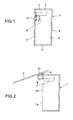
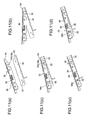
- Fig. 1 is a vertical cross sectional view of a door-equipped cabinet on which the door opening and closing device according to the first embodiment of the present invention is mounted (a door is closed).
- Fig. 2 is a vertical cross sectional view of the door-equipped cabinet (the door is open).
- a door mounting member 1 has a top plate 3, a back plate 4, a bottom plate 5 and a pair of side plates 6.
- the door opening and closing device 7 is fixed to a side plate inner wall 6a of the door mounting member 1.
- a door 2 such as a trap door is mounted via a connecting part 10 mounted on an arm 8 and an auxiliary arm 9.
- the arm 8 and the auxiliary arm 9 rotate, the door 2 opens or closes vertically so that an opening part 1a of the door mounting member 1 is closed or opened.
- the typical door 2 is connected to the door mounting member 1 via a hinge which makes the door 2 rotatable, however, if the door opening and closing device 7 is provided, the hinge is not required.
- Fig. 3 is a perspective view of the door-equipped cabinet (the door is open).
- the door opening and closing devices 7 in a pair are fixed to the side plate inner wall 6a on the respective side of the door mounting member 1 and also mounted on the door 2 via the two connecting parts 10. Therefore, the door 2 is prevented from being twisted relative to the door mounting member 1 and stable opening and closing operation is allowed.
- Fig. 4 illustrates the door opening and closing device 7 according to the first embodiment of the present invention (the door is open) and Fig. 5 illustrates the door opening and closing device 7 (the door is closed).
- a case 11 On the side plate inner wall 6a of the door mounting member 1, a case 11 is mounted.
- the arm 8 and the auxiliary arm 9 are connected to the case 11 rotatably.
- the connecting part 10 is connected to the arm 8 and the auxiliary arm 9 rotatably.
- These case 11, arm 8, auxiliary arm 9 and connecting part 10 form a four-link mechanism.
- a runner 12 is linearly movable relative to the case 11 in the left and right directions of Fig. 4 .
- the runner 12 is connected to an end of a link arm 17 rotatably.
- the other end of the link arm 17 is connected to the arm 8 rotatably around an arm axis 18 which is a rotation center of the arm 8.
- the link arm 17 converts rotational movement of the arm 8 into linear movement of the runner 12.
- the line connecting the rotation center 17-1 of the link arm 17 relative to the runner 12 to the arm axis 18 is a change line L.
- the rotation center 17-2 of the link arm 17 relative to the arm 8 is positioned above the change line L and the runner 12 gives the arm 8 a biasing force in the closing direction so as to maintain the door 2 closed.
- the rotation center 17-2 of the link arm 17 moves below the change line L.
- the runner 12 gives the arm 8 a biasing force in the opening direction.
- the runner 12 gives the biasing force in the opening direction to the arm 8. With this structure, the door 2 is maintained in the open state.
- a friction damper 22 is provided as friction generating means for attenuating the impact when the door 2 gets open.
- the friction damper 22 has a block 12d as a slider and a friction bar 21 as a fixed part which is fixed to the case 11.
- the block 12d has a through hole 12c (see Fig. 6 ) through which the friction bar 21 passes.
- the linear damper 26 is provided below the runner 12, a linear damper 26 is provided for attenuating the impact when the door 2 gets closed.
- the linear damper 26 may be a publicly known linear damper having a cylinder filled with viscous fluid and an extendable rod.
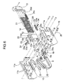
- Fig. 6 is an exploded perspective view of the door opening and closing device 7.
- the case 11 is divided into right and left split cases 11a.
- the runner 12 is housed linearly movable.
- a guide wall 11b is formed for guiding linear movement of the runner 12.
- a stopper 13 is fixed, and at least one (three in Fig. 6 ) compression spring 14 is provided as biasing member.
- the compression spring 14 is provided between the runner 12 and the stopper 13.
- the runner 12 is biased to the left in Fig. 6 by the compression spring 4.
- a reinforcement plate 15 is provided at the left end of the runner 12.
- the runner 12 and the reinforcement plate 15 have axis pin holes 12a and 15a formed therethrough, respectively.
- an axis pin 16 passes through.
- the axis pin 16 also passes through the axis pin hole 17a at one end of the link arm 17 so that the link arm 17 is rotatable relative to the runner 12.
- the arm axis 18 (see Fig. 4 ) is fixed to the left side of the runner 12.
- a rotation base 8a of the arm 8 is made rotatable by the arm axis 18.
- a pivot pin 19 passes through around the arm axis 18 at the rotation base 8a of the arm 8 and the link arm 17 is connected to the pivot pin 19 rotatably.
- the arm 8 is formed jutting from the rotation base 8a and the connecting part 10 to connect to the door 2 is provided at the tip end of the arm 8.
- an auxiliary arm axis 20 is fixed near the arm axis 18 and the auxiliary arm axis 20 is connected rotatably to the auxiliary arm 9.
- the connecting part 10 to connect to the door 2 is provided.
- the connecting part 10 is connected rotatably to the arm 8 and the auxiliary arm 9.
- the block 12d is provided integrally.
- the runner 12 and the block 12d may be formed integral with each other by resin molding or connected by a fastening member like a screw.
- a through hole 12c is formed extending in the moving direction of the runner 12.
- a slit 12b is formed extending in parallel with the through hole 12c and communicating to the through hole 12c.
- the friction bar 21 in parallel with the moving direction of the runner 12 passes therethrough and an end of the friction bar 21 is fixed to the stopper 13.
- Each friction plate 23 has one adjustment screw hole 23a and one adjustment through hole 23b formed therein.
- An adjustment bolt 24 is made to pass from each side of the slit 12b through the adjustment through hole 23b of the friction plate 23 and the adjustment hole 12e of the block 12d and is tightened in the adjustment screw hole 23a of the opposite friction plate 23.
- the block 12d is easily deformed elastically thereby to change the width of the slit 12b. This changes the size of the through hole 12c, thereby adjusting the tightening force between the friction bar 21 and the through hole 12c.
- Fig. 7 (a) is a front view of the door opening and closing device 7 with a cover
- Fig. 7(b) is a front view of the door opening and closing device 7 from which the cover 25 is removed
- Fig. 7(c) is a back view of the door opening and closing device 7 from which the cover 25 is removed.
- the adjustment bolts 24 are tightened from the two directions, that is, the front direction of Fig. 7(b) and the back direction of Fig. 7(c) , they can be tightened and loosened from both of the front side and the back side.
- the linear damper 26 is housed in a damper body 26a. An end of the linear damper 26 abuts to a damper receiver 26d fixed to the case 11. A damper spring 26c is wound around the linear damper 26. The damper spring 26c is provided for increasing the damping force and is provided between the damper body 26a and the damper receiver 26d.
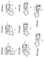
- Fig. 8(a) illustrates the door opening and closing device 7 when the door 2 is closed and the rotation angle of the arm 8 is 0 degree.
- Fig. 8 (b) illustrates the door opening and closing device 7 when the arm 8 rotates 10 degrees in the opening direction
- Figs. 8(c) to 8(h) also illustrate the door opening and closing device 7 as the arm 8 rotates by 10 degrees in the opening direction.
- Fig. 8(h) illustrates the door opening and closing device 7 when the door 2 is opened completely.
- Fig. 8(d) illustrates the door opening and closing device 7 when the arm 8 rotates 30 degrees.
- the force of the compression spring 14 to bias the arm 8 in the opening direction becomes increased so that the door 2 can open automatically.
- the damping force acts on the runner 12, and thereby, it is possible to prevent quick linear movement of the runner 12.
- Fig. 8(h) illustrates the door opening and closing device 7 when the door 2 is open.
- the force of the compression spring 14 to bias the arm 8 is further increased.
- the differential motion of the block 12d relative to the friction bar 21 is further increased, and the damping force from the friction bar 21 is also further increased. Therefore, the impact when the door gets open is attenuated.
- Figs. 8 (a) to 8 (h) Opposite to the opening operation, the door 2 starts to close from the open state of Fig. 8(h) and the arm 8 is rotated. Then, the compression spring 14 is compressed via the runner 12 and the link arm 17. As the door 2 is flipped up at the high position, the torque which acts on the arm 8 is large due to the weight of the door 2 and the compression spring 14 can be easily compressed manually.
- Fig. 8(d) when the rotation angle of the arm 8 is 30 degrees, the rotation base 8a of the arm 8 starts to be in contact with the damper body 26a provided below the runner 12.
- Fig. 8(c) illustrates the door opening and closing device 7 when the door 2 is further rotated in the closing direction.
- the rotation angle of the arm 8 becomes small and the damping force of the friction damper 22 is reduced.
- the linear damper 26 operates, the closing direction of the door 2 becomes slow.
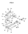
- Fig. 9 is an exploded view of the arm 8, the auxiliary arm 9 and a part of the connecting part 10.
- the arm 8 has a mounting pin hole 8b formed at the tip end opposite to the rotation base 8a.
- the auxiliary arm 9 has an auxiliary mounting pin hole 9a formed at the tip end opposite to the auxiliary arm axis 20.
- mounting holes 27a and 27b are formed so that a plate mounting pin 28 and an auxiliary mounting pin 29 pass through the mounting holes 27a and 27b.
- the mounting plate 27 is pivoted on the tip ends of the arm 8 and auxiliary arm 9 opposite to the runner 12.
- the mounting plate 27 is rotatable by the plate mounting pin 28 and the auxiliary mounting pin 29.
- a mounting member 30 is fixed by fixing pins 31a and 31b.
- stepped pin holes 30a are formed for insertion of stepped pins 32.
- Fig. 10 is an exploded view of a door side mounting part 33.
- a lever 36 is inserted via a mounting spring 35, and the lever 36 is biased to the right in Fig. 10 by the mounting spring 35.
- the door plate 34 has two door side stepped pin holes 34a formed therein and the lever 36 has two lever mounting long holes 36a formed therein.
- Two door side stepped pins 37 are made to pass through the door side stepped pin holes 34a and the lever mounting long holes 36a, respectively, so that the lever 36 can slide until the door side stepped pins 37 abut to the lever mounting long holes 36a (see Fig. 11(a) ).
- the door plate 34 and the lever 36 form the door side mounting part 3 (see Fig. 6 ).
- the door plate 34 is mounted on the door 2 via a door mounting surface 34e.
- FIG. 11 (a) illustrates the mounting member 30 and the door side mounting part 33 which are not yet connected.
- the mounting member 30 has a stepped pin 32 formed on.
- the door side mounting part 33 is arranged such that the lever 36 is biased to the left by the mounting spring 35.
- Fig. 11(b) illustrates a door plate hook 34d and lever hook 36c fit in the right-side stepped pin 32 of the mounting member 30.
- a lever approach part 36b of the lever hook 36c on the front side is longer than an approach part 34b of the door plate hook 34d.
- Fig. 11 (c) illustrates the door side mounting part 33 which is brought close to the mounting member 30 after the door plate hook 34d and the lever hook 36c are fit on the right-side stepped pin 32 of the mounting member 30.
- the left-side stepped pin 32 of the mounting member 30 is in contact with a tapered part 34c of the door plate 34.
- Fig. 11(d) illustrates the door side mounting part 33 which is pressed against the mounting member 30.
- the lever 36 is slid to the right against the spring force of the mounting spring 35, the left-side stepped pin 32 of the mounting member 30 can be fit in the lever lock 36d thereby to be able to connect the mounting member 30 to the door side mounting part 33.
- Fig. 11(e) illustrates the mounting member 30 and the door side mounting part 33 connected to each other.
- the lever lock 36d is slid to the left by the spring force of the mounting spring 35 so that the left-side stepped pin 32 of the mounting member 30 is prevented from being disengaged from the lever lock 36d.
- the door 2 can be easily connected to the mounting member 30 only by rotating the door 2 with use of the upper-side stepped pin 32 and there is no need to get up the door 2.
- the lever 36 When the door 2 is removed from the mounting member 30, the lever 36 is pressed to the right so that the lever 36 and the left-side stepped pin 32 of the mounting member 30 are disengaged. Then, the door 2 is held up while the lever 36 is pressed, the lever 36 is rotated and released from the left-side stepped pin 32 of the mounting member 30 completely (see Fig. 11(b) ).
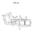
- Fig. 12 illustrates the door opening and closing device according to the second embodiment.
- the block 12d as a fixed part of the friction damper 22 is a separate member from the runner 12 and fixed to the case 11.
- the friction bar 21 as a slider of the friction damper 22 is not fixed to the stopper 13 and is slidable relative to the block 12d.
- an auxiliary axis pin 38 is provided at the tip end on the auxiliary arm 9 side.
- An auxiliary link arm 39 is connected rotatable to the auxiliary axis pin 38.
- an auxiliary pivot pin 40 passes through a rotation base 9b of the auxiliary arm 9 and the auxiliary link arm 39.
- the auxiliary link arm 39 is connected rotatable by the auxiliary pivot pin 40.
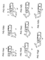
- Figs. 13 (a) to 13 (h) illustrate the door opening and closing device in which the arm 8 rotates by 10 degrees.
- Fig. 13(a) illustrates the door 2 closed, and the rotation angle of the arm 8 is 0 degree.
- the rotation angle of the arm 8 is 20 degrees, the friction bar 21 does not slide and there occurs no damping force.
- Fig. 13(d) the rotation angle of the arm 8 is 30 degrees, the friction bar 21 starts to slide and a damping force starts to be generated. The following process is the same as that in the first embodiment until the door 2 is the open state of Fig. 13 (h) .
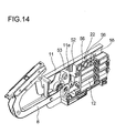
- FIG. 14 is a perspective view of the door opening and closing device according to the third embodiment.
- the runner 12 is connected integrally to sliders 51, 52 (see Fig. 16 ) of the friction damper 22 so that the runner 12 and the sliders of the friction damper 22 can move linearly together.
- a housing case 55 of rectangular shape for housing the friction damper 22 is formed integrally by resin molding.
- the sliders 51 and 52 of the friction damper 22 are connected to this housing case 55.
- a fixed plate 52 as a fixed part of the friction damper 22 is connected integrally to the case 11.
- Fig. 15 is an exploded perspective view of the friction damper 22.
- the friction damper 22 has a fixed plate 53 as a fixed part which is fixed to the case 11 of the door opening and closing device, the sliders 51 and 52 of plate shape in a pair for sandwiching the fixed plate 53 and coil springs 54 as pressing means for pressing the slider 52 toward the fixed plate 53.
- the fixed plate 53 has a rectangular shape and has, at the center, a long hole 53a extending in the moving direction of the runner 12. Around the long hole 53a, a guide groove 53b is formed which is elongated in the moving direction of the runner 12.
- the guide groove 53b has a square center part and semicircular ends.
- a bottom surface (contact part) of the guide groove 53b of the fixed plate 53 in contact with the slider 51 is flat and a back surface (contact part) of the fixed plate 53 in contact with the slider 52 is also flat.
- the fixed plate 53 is, for example, made of resin.
- the fixed plate 53 is fixed to a recess of the case 11. In the case 11, a bent piece 11e (see Fig. 14 ) is formed for fixing the fixed plate 53.
- the slider 51 is fit slidable in the guide groove 53b of the fixed plate 53.
- the slider 51 has a square center part and semicircular ends. In order that the slider 51 is slidable along the guide groove 53b, the length of the slider 51 in the moving direction is shorter than the length of the guide groove 53b of the fixed plate 53.
- a pair of holes 51a is formed for insertion of pins 56.
- a bottom surface (contact part) of the slider 51 in contact with the guide groove 53b is also flat.
- the slider 51 is, for example, made of metal.
- the other slider 52 of plate shape is arranged at the opposite side of the fixed plate 53 to the slider 51.
- This slider 52 has a rectangular shape and both ends 52a in the moving direction are bent at a right angle. The bent ends 52a are fit on the walls of the housing case 55 of the runner 12 (see Fig. 14 ).
- a main body 52b (contact part) of the slider 52 in contact with the fixed plate 53 is flat.
- a pair of holes 52c is formed for insertion of the pins 56.
- the slider 52 is, for example, made of metal.
- the coil springs 54 are provided for pressing the slider 52 toward the fixed plate 53.
- the friction force generated between the fixed plate 53 and the slider 52 is adjusted by an elastic force of these coil springs 54.
- the coil springs 54 press the slider 52 against the fixed plate 53 under a constant pressure even when the fixed plate 53 wears.
- the coil springs 54 are inserted into cylindrical parts 55a of the housing case 55.
- the slider 52 is placed on the coil springs 54 and the both ends 52a of the slider 52 are fit to the walls of the housing case 55.
- the fixed plate 53 is placed on the slider 52 and the slider 51 is fit in the guide groove 53b of the fixed plate 53.
- the paired pins 56 are inserted into the cylindrical parts 55a from the bottom side of the housing case 55 and the pins 56 are made to pass through the holes 51a of the slider 51 so that the two sliders 51 and 52 are integral with the housing case 55.
- the runner 12 is mounted on the case 11.
- the fixed plate 53 of the friction damper 22 is fixed to the case 11.
- the friction damper 22 is comprised of the plate-shaped sliders 51 and 52 and the fixed plate 53, it is easy to assemble the friction damper 22.
- Figs. 16(a) and 16(b) are cross sectional views of the door opening and closing device with the friction damper 22 mounted on.
- the sliders 51 and 52 in a pair for sandwiching the fixed plate 53 are integral with the housing case 55 by the pins 56.
- the sliders 51 and 52 in a pair move linearly in the moving direction of the runner 12 relative to the fixed plate 53 while sandwiching the fixed plate 53.
- the force of the slider 52 to press the fixed plate 53 is adjusted by the coil springs 54.
- the mechanism for synchronizing rotation of the arm with liner movement of the runner is not limited to the link arm, but may be, for example, a cam mechanism. Or, it may be such a mechanism that a long hole is formed in the runner and the pivot pin of the arm is fit in the long hole of the runner.
- the friction damper operates when the door rotates in the closing direction, as well as when the door rotates in the opening direction.
- the operation of the friction damper may be limited to either of when the door rotates in the closing direction and when the door rotates in the opening direction.
- the arm and auxiliary arm form the four-link mechanism, however, the auxiliary may be omitted.
- the runner is used to apply biasing forces in the opening and closing directions.
- a coil spring connected at one end to the arm may be used to apply biasing forces in the opening and closing directions directly to the arm.
Landscapes
- Engineering & Computer Science (AREA)
- Mechanical Engineering (AREA)
- Closing And Opening Devices For Wings, And Checks For Wings (AREA)
Abstract
Description
- The present invention relates to a door opening and closing device, provided between a door and a door mounting member such as a cabinet, for enabling smooth opening and closing operations of the door.
- The door opening and closing device mounted on the door has the function of enabling the manual opening operation of the door easily and by a small force with use of a biasing force of a compression spring and the function of slowing the opening and closing operations of the door by a damping force of a damper (see PL1).
- Such a door opening and closing device has an arm which rotates by opening and closing operations of the door and a runner that is biased by a compression spring to give a biasing force in the opening or closing direction to the arm. The arm and the runner are connected to each other by a link arm which synchronizes rotation of the arm with linear movement of the runner. An end of the link arm is rotatably connected to the runner and the other end of the link arm is rotatably connected to the periphery of the rotation center of the arm. With use of an elastic force of the compression spring, the opening and closing operations of the door can be performed easily by a small force.
- The door opening and closing device is provided with a damper for slowing the opening and closing operations of the door. As the damper is used to brake the opening or closing operation of the door based on the elastic force of the compression spring, the door can open and close slowly.
- The patent literature 1 (PL1) discloses a door opening and closing device in which a rotary damper is used as the above-mentioned damper and is mounted on the rotation axis of the arm. A one-way clutch may be built in the rotary damper thereby to generate a damping force only in opening or closing of the door.
- The patent literature 2 (PL2) discloses an example of using a linear damper. There is provided a neutral range between the opening position and the closing position of the arm, in which range the damping force of the damper is not available. The damping force is set to be generated just before the opening position and closing position of the arm.
-
- PL1: Japanese Patent No.
3300981 - PL2: Japanese Patent Application Laid-Open No.
2007-522363 - However, in the door opening and closing device disclosed in the patent literature 1, the rotary damper generates a fixed damping force while the arm rotates from the closing position to the opening position. Therefore, for example, it is difficult to reduce the damping force when the arm is near the closing position and to increase the damping force when the arm is near the opening position. In order to facilitate the opening direction of the door, it is requested to reduce the damping force when the arm is near the closing position.
- In the door opening and closing device disclosed in the
patent literature 2, the neutral range where the damping force of the damper is not available is provided between the opening position and the closing position of the arm. However, once the damping force is generated, its size or magnitude does not change. Therefore, it is difficult to vary or adjust the damping force in accordance with the degree of opening and closing of the arm. - Then, the present invention aims to provide a door opening and closing device capable of changing a damping force of the damper when the arm rotates by opening and closing of the door.
- In order to solve the above-mentioned problems, a first aspect of the present invention is a door opening and closing device comprising: a case mounted on a door mounting member; an arm which is provided rotatable on the case and rotates by opening and closing of a door; biasing means for applying at least one of a biasing force in an opening direction and a biasing force in a closing direction to the arm; and friction generating means having a slider which moves linearly relative to the case by opening and closing of the door and a fixed part which is fixed to the case to slide the sider, the friction generating means being provide for generating friction between the slider and the fixed part.
- According to the present invention, the friction generating means for generating friction between the slider and the fixed part is used to change a ratio of the rotation angle of the arm and the amount of displacement of the slider. With this structure, it is possible to change the damping force of the friction generating means when the arm rotates by opening and closing of the door. Therefore, it is possible to obtain an appropriate damping force in accordance with the degree of opening and closing of the door.
- The above and other objects and features of the invention will appear more fully hereinafter from a consideration of the following description taken in connection with the accompanying drawing wherein one example is illustrated by way of example, in which;
-
Fig. 1 is a vertical cross sectional view of a door-equipped cabinet (a door is closed); -
Fig. 2 is a vertical cross sectional view of the door-equipped cabinet (the door is open); -
Fig. 3 is a perspective view of the door-equipped cabinet (the door is open); -
Fig. 4 is an assembly view of a door opening and closing device according to a first embodiment of the present invention (the door is open); -
Fig. 5 is an assembly view of the door opening and closing device (the door is closed); -
Fig. 6 is an exploded perspective view of the door opening and closing device; -
Figs. 7(a) to 7(c) are views illustrating the door opening and closing device with or without a cover (Fig. 7(a) is a front view of the door opening and closing device with the cover,Fig. 7 (b) is a front view of the door opening and closing device without cover andFig. 7 (c) is a back view of the door opening and closing device without cover); -
Figs. 8(a) to 8(h) are plan views of the door opening and closing device in which the arm rotates by 10 degrees (Fig. 8(a) illustrates the door closed, andFigs. 8(b) to 8(h) illustrate the arm rotating by 10 degrees.Fig. 8 (h) illustrates the door open) ; -
Fig. 9 is an exploded view of an arm, an auxiliary arm and a part of a connecting part (mounting member); -
Fig. 10 is an exploded view of a door side mounting part; -
Figs. 11(a) to 11(e) are plan views illustrating connection of the mounting member and the door side mounting part (Fig. 11 (a) is a plan view of the mounting member and the door side mounting part which are not yet connected to each other,Figs. 11 (b) to 11 (e) are plan views of the connecting process, andFig. 11(e) is a plan view of the mounting member and the door side mounting part which are completely connected to each other); -
Fig. 12 is a plan view of the door opening and closing device according to a second embodiment of the present invention (the door is open); -
Figs. 13(a) to 13(h) are plan views of the door opening and closing device in which the arm rotates by 10 degrees (Fig. 13(a) illustrates the door closed, andFigs. 13(b) to 13(h) illustrate the arm rotating by 10 degrees.Fig. 13(h) illustrates the door open); -
Fig. 14 is a perspective view of the door opening and closing device according to a third embodiment of the present invention; -
Fig. 15 is an exploded perspective view of a friction damper; and -
Figs. 16(a) and 16(b) are cross sectional views of the door opening and closing device with the friction damper mounted on. - With reference to the attached drawings, description will be made about embodiments of the present invention.
Fig. 1 is a vertical cross sectional view of a door-equipped cabinet on which the door opening and closing device according to the first embodiment of the present invention is mounted (a door is closed).Fig. 2 is a vertical cross sectional view of the door-equipped cabinet (the door is open). - A door mounting member 1 has a
top plate 3, aback plate 4, abottom plate 5 and a pair ofside plates 6. The door opening andclosing device 7 is fixed to a side plateinner wall 6a of the door mounting member 1. On the door opening andclosing device 7, adoor 2 such as a trap door is mounted via a connectingpart 10 mounted on anarm 8 and anauxiliary arm 9. When thearm 8 and theauxiliary arm 9 rotate, thedoor 2 opens or closes vertically so that anopening part 1a of the door mounting member 1 is closed or opened. Thetypical door 2 is connected to the door mounting member 1 via a hinge which makes thedoor 2 rotatable, however, if the door opening andclosing device 7 is provided, the hinge is not required. -
Fig. 3 is a perspective view of the door-equipped cabinet (the door is open). The door opening andclosing devices 7 in a pair are fixed to the side plateinner wall 6a on the respective side of the door mounting member 1 and also mounted on thedoor 2 via the two connectingparts 10. Therefore, thedoor 2 is prevented from being twisted relative to the door mounting member 1 and stable opening and closing operation is allowed. -
Fig. 4 illustrates the door opening andclosing device 7 according to the first embodiment of the present invention (the door is open) andFig. 5 illustrates the door opening and closing device 7 (the door is closed). On the side plateinner wall 6a of the door mounting member 1, acase 11 is mounted. Thearm 8 and theauxiliary arm 9 are connected to thecase 11 rotatably. The connectingpart 10 is connected to thearm 8 and theauxiliary arm 9 rotatably. Thesecase 11,arm 8,auxiliary arm 9 and connectingpart 10 form a four-link mechanism. - When the
door 2 is opened or closed manually, thearm 8 and theauxiliary arm 9 rotate from the closed position ofFig. 5 to the open position ofFig. 4 . Arunner 12 is linearly movable relative to thecase 11 in the left and right directions ofFig. 4 . Therunner 12 is connected to an end of alink arm 17 rotatably. The other end of thelink arm 17 is connected to thearm 8 rotatably around anarm axis 18 which is a rotation center of thearm 8. Thelink arm 17 converts rotational movement of thearm 8 into linear movement of therunner 12. - The line connecting the rotation center 17-1 of the
link arm 17 relative to therunner 12 to thearm axis 18 is a change line L. As illustrated inFig. 5 , when thedoor 2 is closed, the rotation center 17-2 of thelink arm 17 relative to thearm 8 is positioned above the change line L and therunner 12 gives thearm 8 a biasing force in the closing direction so as to maintain thedoor 2 closed. When thedoor 2 is rotated in the opening direction manually, the rotation center 17-2 of thelink arm 17 moves below the change line L. Then, therunner 12 gives thearm 8 a biasing force in the opening direction. As illustrated inFig. 4 , when thedoor 2 is opened, therunner 12 gives the biasing force in the opening direction to thearm 8. With this structure, thedoor 2 is maintained in the open state. - Above the
runner 12, afriction damper 22 is provided as friction generating means for attenuating the impact when thedoor 2 gets open. Thefriction damper 22 has ablock 12d as a slider and afriction bar 21 as a fixed part which is fixed to thecase 11. Theblock 12d has a through hole 12c (seeFig. 6 ) through which thefriction bar 21 passes. When thedoor 2 opens or closes, theblock 12d moves linearly relative to thecase 11. When theblock 12d moves linearly relative to thecase 11, theblock 12d slides thefriction bar 21 thereby to generate friction between theblock 12d and thefriction bar 21. - Below the
runner 12, alinear damper 26 is provided for attenuating the impact when thedoor 2 gets closed. Thelinear damper 26 may be a publicly known linear damper having a cylinder filled with viscous fluid and an extendable rod. -
Fig. 6 is an exploded perspective view of the door opening andclosing device 7. Thecase 11 is divided into right and left splitcases 11a. In thecase 11, therunner 12 is housed linearly movable. In thecase 11, aguide wall 11b is formed for guiding linear movement of therunner 12. At the right end of thecase 11 inFig. 6 , astopper 13 is fixed, and at least one (three inFig. 6 )compression spring 14 is provided as biasing member. Thecompression spring 14 is provided between therunner 12 and thestopper 13. Therunner 12 is biased to the left inFig. 6 by thecompression spring 4. - At the left end of the
runner 12, areinforcement plate 15 is provided. Therunner 12 and thereinforcement plate 15 have axis pin holes 12a and 15a formed therethrough, respectively. In the axis pin holes 12a and 15a, an axis pin 16 passes through. The axis pin 16 also passes through theaxis pin hole 17a at one end of thelink arm 17 so that thelink arm 17 is rotatable relative to therunner 12. - In the
case 11, the arm axis 18 (seeFig. 4 ) is fixed to the left side of therunner 12. Arotation base 8a of thearm 8 is made rotatable by thearm axis 18. Apivot pin 19 passes through around thearm axis 18 at therotation base 8a of thearm 8 and thelink arm 17 is connected to thepivot pin 19 rotatably. - The
arm 8 is formed jutting from therotation base 8a and the connectingpart 10 to connect to thedoor 2 is provided at the tip end of thearm 8. In thecase 11, anauxiliary arm axis 20 is fixed near thearm axis 18 and theauxiliary arm axis 20 is connected rotatably to theauxiliary arm 9. At the tip end of theauxiliary arm 9, the connectingpart 10 to connect to thedoor 2 is provided. The connectingpart 10 is connected rotatably to thearm 8 and theauxiliary arm 9. - On the
runner 12, theblock 12d is provided integrally. Therunner 12 and theblock 12d may be formed integral with each other by resin molding or connected by a fastening member like a screw. In theblock 12d, a through hole 12c is formed extending in the moving direction of therunner 12. In theblock 12d, aslit 12b is formed extending in parallel with the through hole 12c and communicating to the through hole 12c. In the through hole 12c, thefriction bar 21 in parallel with the moving direction of therunner 12 passes therethrough and an end of thefriction bar 21 is fixed to thestopper 13. - Next description is made about the adjustment method of the friction force of the
friction damper 22. At both, right and left, ends of theblock 12d,respective friction plates 23 are provided in a pair. Eachfriction plate 23 has oneadjustment screw hole 23a and one adjustment throughhole 23b formed therein. Anadjustment bolt 24 is made to pass from each side of theslit 12b through the adjustment throughhole 23b of thefriction plate 23 and theadjustment hole 12e of theblock 12d and is tightened in theadjustment screw hole 23a of theopposite friction plate 23. By the tightening force of theadjustment bolt 24, theblock 12d is easily deformed elastically thereby to change the width of theslit 12b. This changes the size of the through hole 12c, thereby adjusting the tightening force between thefriction bar 21 and the through hole 12c. -
Fig. 7 (a) is a front view of the door opening andclosing device 7 with acover 25,Fig. 7(b) is a front view of the door opening andclosing device 7 from which thecover 25 is removed andFig. 7(c) is a back view of the door opening andclosing device 7 from which thecover 25 is removed. As theadjustment bolts 24 are tightened from the two directions, that is, the front direction ofFig. 7(b) and the back direction ofFig. 7(c) , they can be tightened and loosened from both of the front side and the back side. - When the
block 12d moves linearly, there is produced a friction force between the through hole 12c and thefriction bar 21 thereby to brake the linear movement of theblock 12d. As theblock 12d of thefriction damper 22 is integral with therunner 12, the friction force generated by differential motion of thefriction bar 21 and theblock 12d directly acts on therunner 12. Therefore, it is not necessary to provide a separate mechanism for moving theblock 12d linearly and the number of components can be reduced. - As illustrated in
Fig. 6 , thelinear damper 26 is housed in adamper body 26a. An end of thelinear damper 26 abuts to adamper receiver 26d fixed to thecase 11. Adamper spring 26c is wound around thelinear damper 26. Thedamper spring 26c is provided for increasing the damping force and is provided between thedamper body 26a and thedamper receiver 26d. - Next description is made, with reference to
Figs. 8 (a) to 8 (h) , about the relation between the rotational movement of thearm 8 by opening and closing of thedoor 2 and the linear movement of the runner 12 (block 12d) in synchronization with the rotational movement of thearm 8. The rotational movement of thearm 8 is converted to the linear movement of therunner 12 by thelink arm 17. -
Fig. 8(a) illustrates the door opening andclosing device 7 when thedoor 2 is closed and the rotation angle of thearm 8 is 0 degree.Fig. 8 (b) illustrates the door opening andclosing device 7 when thearm 8 rotates 10 degrees in the opening direction, andFigs. 8(c) to 8(h) also illustrate the door opening andclosing device 7 as thearm 8 rotates by 10 degrees in the opening direction.Fig. 8(h) illustrates the door opening andclosing device 7 when thedoor 2 is opened completely. - As illustrated in
Figs. 8 (a) to 8 (c) , when the rotation angle of thearm 8 is changed from 0 to 20 degrees, thepivot pin 19 moves mainly downward and therefore, thelink arm 17 is rotated by the axis pin 16 but therunner 12 almost moves linearly. Therefore, there occurs almost no differential motion of theblock 12d relative to thefriction bar 21, and it is possible to open thedoor 2 by a small force until thearm 8 rotates up to 20 degrees. -
Fig. 8(d) illustrates the door opening andclosing device 7 when thearm 8 rotates 30 degrees. When the rotation angle of thearm 7 exceeds 30 degrees, the force of thecompression spring 14 to bias thearm 8 in the opening direction becomes increased so that thedoor 2 can open automatically. On the other hand, as the differential motion of theblock 12d relative to thefriction bar 21 also increases, the damping force acts on therunner 12, and thereby, it is possible to prevent quick linear movement of therunner 12. -
Fig. 8(h) illustrates the door opening andclosing device 7 when thedoor 2 is open. Immediately before thedoor 2 gets open, the force of thecompression spring 14 to bias thearm 8 is further increased. However, the differential motion of theblock 12d relative to thefriction bar 21 is further increased, and the damping force from thefriction bar 21 is also further increased. Therefore, the impact when the door gets open is attenuated. - In this way, as the ratio of the rotation angle of the
arm 8 and the amount of displacement of therunner 12 is changed, it is possible to reduce the damping force of thefriction damper 22 when the rotation angle of thearm 8 is small and to increase the damping force of thefriction damper 22 when the rotation angle of thearm 8 is large. Therefore, it is possible to obtain an appropriate damping force in accordance with the degree of opening and closing of thearm 8. - Next, the closing process of the
door 2 is described with reference toFigs. 8 (a) to 8 (h) . Opposite to the opening operation, thedoor 2 starts to close from the open state ofFig. 8(h) and thearm 8 is rotated. Then, thecompression spring 14 is compressed via therunner 12 and thelink arm 17. As thedoor 2 is flipped up at the high position, the torque which acts on thearm 8 is large due to the weight of thedoor 2 and thecompression spring 14 can be easily compressed manually. - As illustrated in
Fig. 8(d) , when the rotation angle of thearm 8 is 30 degrees, therotation base 8a of thearm 8 starts to be in contact with thedamper body 26a provided below therunner 12.Fig. 8(c) illustrates the door opening andclosing device 7 when thedoor 2 is further rotated in the closing direction. The rotation angle of thearm 8 becomes small and the damping force of thefriction damper 22 is reduced. However, as thelinear damper 26 operates, the closing direction of thedoor 2 becomes slow. - Next description is made about the structure and operation of the connecting
part 10. -
Fig. 9 is an exploded view of thearm 8, theauxiliary arm 9 and a part of the connectingpart 10. Thearm 8 has a mountingpin hole 8b formed at the tip end opposite to therotation base 8a. Theauxiliary arm 9 has an auxiliarymounting pin hole 9a formed at the tip end opposite to theauxiliary arm axis 20. At both ends of a mountingplate 27, mountingholes plate mounting pin 28 and anauxiliary mounting pin 29 pass through the mountingholes plate 27 is pivoted on the tip ends of thearm 8 andauxiliary arm 9 opposite to therunner 12. The mountingplate 27 is rotatable by theplate mounting pin 28 and theauxiliary mounting pin 29. To the mountingplate 27, a mountingmember 30 is fixed by fixingpins member 30, steppedpin holes 30a are formed for insertion of stepped pins 32. -
Fig. 10 is an exploded view of a doorside mounting part 33. In adoor plate 34, alever 36 is inserted via a mountingspring 35, and thelever 36 is biased to the right inFig. 10 by the mountingspring 35. Thedoor plate 34 has two door side steppedpin holes 34a formed therein and thelever 36 has two lever mountinglong holes 36a formed therein. Two door side stepped pins 37 are made to pass through the door side steppedpin holes 34a and the lever mountinglong holes 36a, respectively, so that thelever 36 can slide until the door side stepped pins 37 abut to the lever mountinglong holes 36a (seeFig. 11(a) ). Thedoor plate 34 and thelever 36 form the door side mounting part 3 (seeFig. 6 ). Thedoor plate 34 is mounted on thedoor 2 via adoor mounting surface 34e. - Next description is made, with reference to
Figs. 11(a) to 11(e) , about the connecting method of the mountingmember 30 and the doorside mounting part 33.Fig. 11 (a) illustrates the mountingmember 30 and the doorside mounting part 33 which are not yet connected. The mountingmember 30 has a steppedpin 32 formed on. The doorside mounting part 33 is arranged such that thelever 36 is biased to the left by the mountingspring 35. -
Fig. 11(b) illustrates adoor plate hook 34d andlever hook 36c fit in the right-side steppedpin 32 of the mountingmember 30. As illustrated inFig. 10 , alever approach part 36b of thelever hook 36c on the front side is longer than anapproach part 34b of thedoor plate hook 34d. With this structure, even when thelever 36 is biased by the mountingspring 35, theapproach part 34b of thedoor plate hook 34d is prevented from being narrowed by thelever approach part 36b. Therefore, easy fitting is allowed. -
Fig. 11 (c) illustrates the doorside mounting part 33 which is brought close to the mountingmember 30 after thedoor plate hook 34d and thelever hook 36c are fit on the right-side steppedpin 32 of the mountingmember 30. The left-side steppedpin 32 of the mountingmember 30 is in contact with atapered part 34c of thedoor plate 34. - Further,
Fig. 11(d) illustrates the doorside mounting part 33 which is pressed against the mountingmember 30. As thelever 36 is slid to the right against the spring force of the mountingspring 35, the left-side steppedpin 32 of the mountingmember 30 can be fit in thelever lock 36d thereby to be able to connect the mountingmember 30 to the doorside mounting part 33. -
Fig. 11(e) illustrates the mountingmember 30 and the doorside mounting part 33 connected to each other. When the left-side steppedpin 32 of the mountingmember 30 is fit in thelever lock 36d, thelever lock 36d is slid to the left by the spring force of the mountingspring 35 so that the left-side steppedpin 32 of the mountingmember 30 is prevented from being disengaged from thelever lock 36d. - As described above, after the
door plate hook 34d and thelever hook 36c of the upper side of the doorside mounting part 33 mounted on thedoor 2 are fit on the stepped pins 32 of the mountingmember 30, thedoor 2 can be easily connected to the mountingmember 30 only by rotating thedoor 2 with use of the upper-side steppedpin 32 and there is no need to get up thedoor 2. - When the
door 2 is removed from the mountingmember 30, thelever 36 is pressed to the right so that thelever 36 and the left-side steppedpin 32 of the mountingmember 30 are disengaged. Then, thedoor 2 is held up while thelever 36 is pressed, thelever 36 is rotated and released from the left-side steppedpin 32 of the mountingmember 30 completely (seeFig. 11(b) ). - Next description is made about a door opening and closing device according to the second embodiment of the present invention.
Fig. 12 illustrates the door opening and closing device according to the second embodiment. - In this embodiment, the
block 12d as a fixed part of thefriction damper 22 is a separate member from therunner 12 and fixed to thecase 11. Thefriction bar 21 as a slider of thefriction damper 22 is not fixed to thestopper 13 and is slidable relative to theblock 12d. At the tip end on theauxiliary arm 9 side, anauxiliary axis pin 38 is provided. An end of anauxiliary link arm 39 is connected rotatable to theauxiliary axis pin 38. Besides, around theauxiliary arm axis 20, anauxiliary pivot pin 40 passes through arotation base 9b of theauxiliary arm 9 and theauxiliary link arm 39. Theauxiliary link arm 39 is connected rotatable by theauxiliary pivot pin 40. As theauxiliary arm 9 rotates by opening and closing of thedoor 2, theauxiliary link arm 39 slides thefriction bar 21 thereby to produce a damping force. - Next description is made about the relation between rotation of the
arm 8 and sliding of thefriction bar 21 with reference toFigs. 13(a) to 13(h) . -
Figs. 13 (a) to 13 (h) illustrate the door opening and closing device in which thearm 8 rotates by 10 degrees.Fig. 13(a) illustrates thedoor 2 closed, and the rotation angle of thearm 8 is 0 degree. InFig. 13(c) , the rotation angle of thearm 8 is 20 degrees, thefriction bar 21 does not slide and there occurs no damping force. InFig. 13(d) , the rotation angle of thearm 8 is 30 degrees, thefriction bar 21 starts to slide and a damping force starts to be generated. The following process is the same as that in the first embodiment until thedoor 2 is the open state ofFig. 13 (h) . - In the second embodiment, sliding of the
runner 12 and thefriction damper 22 is adjusted by theauxiliary link arm 39 pivoted to therotation base 9b of theauxiliary arm 9 and thelink arm 17 pivoted to therotation base 8a of thearm 8. As thefriction damper 22 and therunner 12 slide separately by opening and closing of thedoor 2, it is possible to set the damping force by friction and the biasing force by thecompression spring 14 in an appropriate manner. - Next description is made about a door opening and closing device according to the third embodiment of the present invention.
Fig. 14 is a perspective view of the door opening and closing device according to the third embodiment. - In the door opening and closing device according to the third embodiment, like the door opening and closing device in the first embodiment, the
runner 12 is connected integrally tosliders 51, 52 (seeFig. 16 ) of thefriction damper 22 so that therunner 12 and the sliders of thefriction damper 22 can move linearly together. On therunner 12, ahousing case 55 of rectangular shape for housing thefriction damper 22 is formed integrally by resin molding. Thesliders friction damper 22 are connected to thishousing case 55. A fixedplate 52 as a fixed part of thefriction damper 22 is connected integrally to thecase 11. -
Fig. 15 is an exploded perspective view of thefriction damper 22. Thefriction damper 22 has a fixedplate 53 as a fixed part which is fixed to thecase 11 of the door opening and closing device, thesliders plate 53 andcoil springs 54 as pressing means for pressing theslider 52 toward the fixedplate 53. - The fixed
plate 53 has a rectangular shape and has, at the center, along hole 53a extending in the moving direction of therunner 12. Around thelong hole 53a, aguide groove 53b is formed which is elongated in the moving direction of therunner 12. Theguide groove 53b has a square center part and semicircular ends. A bottom surface (contact part) of theguide groove 53b of the fixedplate 53 in contact with theslider 51 is flat and a back surface (contact part) of the fixedplate 53 in contact with theslider 52 is also flat. The fixedplate 53 is, for example, made of resin. The fixedplate 53 is fixed to a recess of thecase 11. In thecase 11, abent piece 11e (seeFig. 14 ) is formed for fixing the fixedplate 53. - The
slider 51 is fit slidable in theguide groove 53b of the fixedplate 53. Theslider 51 has a square center part and semicircular ends. In order that theslider 51 is slidable along theguide groove 53b, the length of theslider 51 in the moving direction is shorter than the length of theguide groove 53b of the fixedplate 53. At the center part of theslider 51, a pair ofholes 51a is formed for insertion ofpins 56. A bottom surface (contact part) of theslider 51 in contact with theguide groove 53b is also flat. Theslider 51 is, for example, made of metal. - At the opposite side of the fixed
plate 53 to theslider 51, theother slider 52 of plate shape is arranged. Thisslider 52 has a rectangular shape and bothends 52a in the moving direction are bent at a right angle. The bent ends 52a are fit on the walls of thehousing case 55 of the runner 12 (seeFig. 14 ). Amain body 52b (contact part) of theslider 52 in contact with the fixedplate 53 is flat. At the center part of theslider 52, a pair ofholes 52c is formed for insertion of thepins 56. Theslider 52 is, for example, made of metal. - Between the
slider 52 and thehousing case 55, the coil springs 54 are provided for pressing theslider 52 toward the fixedplate 53. The friction force generated between the fixedplate 53 and theslider 52 is adjusted by an elastic force of these coil springs 54. The coil springs 54 press theslider 52 against the fixedplate 53 under a constant pressure even when the fixedplate 53 wears. - In assembling the
friction damper 22, first, the coil springs 54 are inserted intocylindrical parts 55a of thehousing case 55. Theslider 52 is placed on the coil springs 54 and the both ends 52a of theslider 52 are fit to the walls of thehousing case 55. Next, the fixedplate 53 is placed on theslider 52 and theslider 51 is fit in theguide groove 53b of the fixedplate 53. The paired pins 56 are inserted into thecylindrical parts 55a from the bottom side of thehousing case 55 and thepins 56 are made to pass through theholes 51a of theslider 51 so that the twosliders housing case 55. Once thefriction damper 22 is assembled, therunner 12 is mounted on thecase 11. Then, the fixedplate 53 of thefriction damper 22 is fixed to thecase 11. In this embodiment, as thefriction damper 22 is comprised of the plate-shapedsliders plate 53, it is easy to assemble thefriction damper 22. -
Figs. 16(a) and 16(b) are cross sectional views of the door opening and closing device with thefriction damper 22 mounted on. Thesliders plate 53 are integral with thehousing case 55 by thepins 56. Thesliders runner 12 relative to the fixedplate 53 while sandwiching the fixedplate 53. The force of theslider 52 to press the fixedplate 53 is adjusted by the coil springs 54. - Here, the present invention is not limited to the above-described embodiments and may be embodied in various modified forms without departing from the scope of the present invention. For example, the mechanism for synchronizing rotation of the arm with liner movement of the runner is not limited to the link arm, but may be, for example, a cam mechanism. Or, it may be such a mechanism that a long hole is formed in the runner and the pivot pin of the arm is fit in the long hole of the runner.
- In the above-described embodiments, the friction damper operates when the door rotates in the closing direction, as well as when the door rotates in the opening direction. However, the operation of the friction damper may be limited to either of when the door rotates in the closing direction and when the door rotates in the opening direction.
- In the above-described embodiments, the arm and auxiliary arm form the four-link mechanism, however, the auxiliary may be omitted.
- In the above-described embodiments, the runner is used to apply biasing forces in the opening and closing directions. However, a coil spring connected at one end to the arm may be used to apply biasing forces in the opening and closing directions directly to the arm.
- The present specification is based on Japanese Patent Application No.
2010-094715 filed on April 16, 2010 -
- 1...
- door mounting member
- 2...
- door
- 7...
- door opening and closing device
- 8...
- arm
- 8a...
- rotation base
- 11...
- case
- 12...
- runner
- 12b...
- slit
- 12c...
- through hole (hole)
- 12d...
- block (slider, fixed body)
- 14...
- compression spring (biasing means)
- 17...
- link arm
- 21...
- friction bar (slider, fixed body)
- 22...
- friction generating means (friction damper)
- 24...
- adjustment bolt
- 26...
- linear damper
Claims (7)
- A door opening and closing device comprising:a case mounted on a door mounting member;an arm which is provided rotatable on the case and rotates by opening and closing of a door;biasing means for applying at least one of a biasing force in an opening direction and a biasing force in a closing direction to the arm; andfriction generating means having a slider which moves linearly relative to the case by opening and closing of the door and a fixed part which is fixed to the case to slide the sider, the friction generating means being provided for generating friction between the slider and the fixed part.
- The door opening and closing device of claim 1, wherein
the door opening and closing device further comprises a runner which is provided linearly movable on the case and is biased by the biasing means to apply at least one of the biasing force in the opening direction and the biasing force in the closing direction to the arm,
the runner and the slider of the friction generating means are linearly movable together, and
a damping force of the friction generating means acts on the runner via the slider. - The door opening and closing device of claim 2, wherein
the slider and the fixed part of the friction generating means have respective contact parts where the slider and the fixed part are in contact with each other, and
the friction generating means further includes pressing means for pressing one of the contact parts of the slider and the fixed part toward the other. - The door opening and closing device of claim 2 or 3, wherein
the door opening and closing device further comprises a link arm which has one end connected rotatable to the runner and an opposite end connected rotatable to the arm around a rotation center of the arm, and
the link arm is used to synchronize rotation of the arm with linear movement of the runner. - The door opening and closing device of claim 2, wherein
either one of the slider and the fixed part of the friction generating means has a friction bar which is in parallel with a direction of linear movement of the runner, and
the other of the slider and the fixed part of the friction generating means has a hole for insertion of the friction bar. - The door opening and closing device of claim 5, wherein
the other of the slider and the fixed part of the friction generating means has a slit which is linked to the hole, and
an adjustment bolt is used to adjust a width of the slit thereby to adjust a size of the hole for insertion of the friction bar. - The door opening and closing device of any one of claims 1 to 6, wherein the door opening and closing device further comprises a linear damper for braking rotation of the arm just before the
arm rotates up to a fully open position or fully closed position.
Applications Claiming Priority (2)
| Application Number | Priority Date | Filing Date | Title |
|---|---|---|---|
| JP2010094715 | 2010-04-16 | ||
| PCT/JP2011/054453 WO2011129154A1 (en) | 2010-04-16 | 2011-02-28 | Door opening/closing apparatus |
Publications (2)
| Publication Number | Publication Date |
|---|---|
| EP2559835A1 true EP2559835A1 (en) | 2013-02-20 |
| EP2559835A4 EP2559835A4 (en) | 2017-12-20 |
Family
ID=44798533
Family Applications (1)
| Application Number | Title | Priority Date | Filing Date |
|---|---|---|---|
| EP11768675.8A Withdrawn EP2559835A4 (en) | 2010-04-16 | 2011-02-28 | Door opening/closing apparatus |
Country Status (6)
| Country | Link |
|---|---|
| US (1) | US8959709B2 (en) |
| EP (1) | EP2559835A4 (en) |
| JP (1) | JP5364162B2 (en) |
| CN (1) | CN102782237B (en) |
| TW (1) | TWI499714B (en) |
| WO (1) | WO2011129154A1 (en) |
Cited By (4)
| Publication number | Priority date | Publication date | Assignee | Title |
|---|---|---|---|---|
| WO2017143378A1 (en) * | 2016-02-26 | 2017-08-31 | Julius Blum Gmbh | Actuating arm drive |
| US20190316397A1 (en) * | 2018-04-17 | 2019-10-17 | Grass Gmbh | Device for moving a furniture part, and item of furniture |
| EP3556978A1 (en) * | 2018-04-17 | 2019-10-23 | Grass GmbH | Device for moving a piece of furniture on a body of a piece of furniture |
| EP3569806A1 (en) * | 2018-05-17 | 2019-11-20 | Kesseböhmer Holding KG | Lid fitting for swingable mounting of a furniture lid to a furniture unit |
Families Citing this family (46)
| Publication number | Priority date | Publication date | Assignee | Title |
|---|---|---|---|---|
| USD716130S1 (en) * | 2011-10-14 | 2014-10-28 | Sugatsune Kogyo Co., Ltd. | Hinge for furniture |
| USD716129S1 (en) * | 2011-10-14 | 2014-10-28 | Sugatsune Kogyo Co., Ltd. | Hinge for furniture |
| RU2573292C1 (en) * | 2012-01-30 | 2016-01-20 | Юлиус Блум Гмбх | Actuator for flap door of furniture item |
| CN104583518B (en) * | 2012-09-25 | 2016-10-26 | 世嘉智尼工业株式会社 | Door leaf opening and closing device |
| USD721953S1 (en) * | 2012-10-31 | 2015-02-03 | Sugatsune Kogyo Co., Ltd. | Stay for furniture |
| DE102013101040A1 (en) * | 2013-02-01 | 2014-08-07 | Hettich-Oni Gmbh & Co. Kg | Multi-joint hinge with damping |
| DE102014113970B4 (en) * | 2014-09-26 | 2016-08-18 | Samet Kalip Ve Maden Esya San. Ve Tic. A.S. | hinge |
| DE102014113967B4 (en) * | 2014-09-26 | 2016-09-01 | Samet Kalip Ve Maden Esya San. Ve Tic. A.S. | Furniture hinge and furniture |
| TWI550176B (en) * | 2014-11-21 | 2016-09-21 | 葉任平 | Spindle automatic return device with speed adjustment |
| BR112017016032A2 (en) * | 2015-02-17 | 2018-03-20 | Salice Arturo Spa | furniture sheet lifting system |
| SI3289158T1 (en) * | 2015-04-30 | 2021-11-30 | Arturo Salice S.P.A. | Hinge for furniture leaves that swing about at least one horizontal axis |
| FR3041315B1 (en) * | 2015-09-17 | 2018-09-14 | Faurecia Bloc Avant | TWO-BILLET TAILGATE OPENING SYSTEM |
| DE102015117291C5 (en) * | 2015-10-09 | 2020-03-26 | Samet Kalip Ve Maden Esya San. Ve Tic. A.S. | Flap holder for a furniture flap |
| ITUB20156022A1 (en) * | 2015-11-30 | 2017-05-30 | Leandro Cappellotto | MOVEMENT MECHANISM OF FURNITURE DOORS |
| AT16381U1 (en) * | 2016-02-26 | 2019-08-15 | Blum Gmbh Julius | Deputy arm drive |
| AT16333U1 (en) * | 2016-03-11 | 2019-07-15 | Blum Gmbh Julius | Actuator for driving a movably mounted furniture part |
| CN105735813B (en) * | 2016-04-21 | 2017-03-22 | 博洛尼家居用品湖北有限公司 | Double-cylinder turnover door supporting device |
| AT518621B1 (en) * | 2016-05-13 | 2018-10-15 | Blum Gmbh Julius | actuator |
| CN106978951B (en) * | 2016-09-19 | 2019-05-10 | 上海品贵国际贸易有限公司 | Arbor automatic homing device with deceleration or rate controlling function |
| IT201600098088A1 (en) * | 2016-09-30 | 2018-03-30 | Salice Arturo Spa | Control device for a lifting system and lifting system for furniture doors. |
| JP6819998B2 (en) * | 2016-10-31 | 2021-01-27 | 株式会社ナチュラレーザ・ワン | Door body opening / closing device and various cabinets equipped with this door body opening / closing device |
| AT519900B1 (en) * | 2017-05-12 | 2020-02-15 | Blum Gmbh Julius | furniture drive |
| JP6893688B2 (en) | 2017-06-20 | 2021-06-23 | 株式会社ナチュラレーザ・ワン | Switchgear switchgear and various switchgear equipped with this switchgear switchgear |
| DE102017114772A1 (en) * | 2017-07-03 | 2019-01-03 | Hettich-Oni Gmbh & Co. Kg | Flap fitting and furniture |
| KR102542543B1 (en) * | 2017-09-29 | 2023-06-14 | 삼성전자주식회사 | Household apparatus |
| DE102017126367A1 (en) * | 2017-11-10 | 2019-05-16 | Hettich-Oni Gmbh & Co. Kg | Flap fitting for a furniture, side wall of a furniture body and furniture with a side wall |
| DE102017126369A1 (en) * | 2017-11-10 | 2019-05-16 | Hettich-Oni Gmbh & Co. Kg | Flap fitting for a furniture, side wall of a furniture body and furniture with a side wall |
| DK179893B9 (en) * | 2017-11-24 | 2019-10-03 | Vkr Holding A/S | Lifting device including a sledge system for installation in a roof window and a roof window comprising such a lifting device |
| KR102013042B1 (en) * | 2017-12-22 | 2019-08-21 | 서원코리아 주식회사 | Door Hinge |
| JP7064742B2 (en) * | 2017-12-27 | 2022-05-11 | 株式会社ナチュラレーザ・ワン | Switchgear and game console |
| US10745953B2 (en) * | 2018-01-16 | 2020-08-18 | Dongguan Coomo Furniture Co., Ltd. | Support device and folding furniture having the same |
| JP6769684B2 (en) * | 2018-04-25 | 2020-10-14 | スガツネ工業株式会社 | Hinge device mounting structure |
| IT201800009883A1 (en) * | 2018-10-30 | 2020-04-30 | Effegi Brevetti Srl | MECHANISM FOR HANDLING A FLAP DOWNWARDS |
| TR201818259A2 (en) * | 2018-11-30 | 2020-06-22 | Samet Kalip Ve Madeni Esya Sanayi Ve Ticaret Anonim Sirketi | A Furniture Hinge for Upward-Opening Cabinet Doors |
| AT522446B1 (en) | 2019-05-17 | 2020-11-15 | Blum Gmbh Julius | Furniture drive |
| DE102019113337B4 (en) * | 2019-05-20 | 2022-07-14 | Samet Kalip Ve Maden Esya San. Ve Tic. A.S. | furniture fitting |
| DE102019113338A1 (en) * | 2019-05-20 | 2020-11-26 | Samet Kalip Ve Maden Esya San. Ve Tic. A.S. | Furniture fittings |
| KR102165701B1 (en) * | 2020-01-02 | 2020-10-14 | 풍원공업 주식회사 | Muti-link hinge |
| AT523757B1 (en) * | 2020-05-07 | 2023-07-15 | Blum Gmbh Julius | furniture drive |
| AT524339B1 (en) * | 2020-10-22 | 2023-10-15 | Blum Gmbh Julius | Furniture drive for moving a furniture front |
| AT524384A1 (en) * | 2020-10-22 | 2022-05-15 | Blum Gmbh Julius | Drive device for a movable furniture part |
| US11920401B2 (en) | 2021-05-03 | 2024-03-05 | Kohler Co. | Slow close mechanism for sliding applications |
| IT202100025982A1 (en) * | 2021-10-11 | 2023-04-11 | Effegi Brevetti Srl | LIFTING DOOR OPENING DEVICE |
| CN114382371B (en) * | 2022-01-06 | 2025-07-04 | 李浮云 | An automatic and gradually unfolding door opening device |
| IT202200001286A1 (en) * | 2022-01-26 | 2023-07-26 | Effegi Brevetti Srl | MECHANISM FOR MOVEMENT OF A FLAP DOOR UPWARDS |
| CN119145730A (en) * | 2024-11-18 | 2024-12-17 | 广东图特精密五金科技股份有限公司 | Door moving device with anti-shaking function |
Family Cites Families (27)
| Publication number | Priority date | Publication date | Assignee | Title |
|---|---|---|---|---|
| US3555591A (en) * | 1968-06-25 | 1971-01-19 | Nash P Sogoian | Friction-type door check |
| US3765053A (en) * | 1972-08-28 | 1973-10-16 | Magnavox Co | Friction support for lids |
| DE2717196A1 (en) * | 1977-04-19 | 1978-11-02 | Hettich Hetal Werke | Sprung hinge arm for up-and-over cupboard door - has adjustable springs and geometry to suit range of applications |
| JPS5823902Y2 (en) * | 1977-10-19 | 1983-05-21 | 松下電器産業株式会社 | Lid opening/closing device |
| JPS5836174B2 (en) | 1977-11-07 | 1983-08-08 | 三菱自動車工業株式会社 | Exhaust gas purification device |
| US4190274A (en) * | 1978-01-23 | 1980-02-26 | David Gross | Friction support device |
| DE2853971A1 (en) * | 1978-12-14 | 1980-07-03 | Hettich Hetal Werke | Folding furniture flap linkage - has unequal length connecting arms forming irregular rectangle working together with spring device |
| JPS6254197A (en) | 1985-09-03 | 1987-03-09 | Citizen Watch Co Ltd | Structure of small-sized electronic equipment |
| JPH0438078Y2 (en) * | 1985-09-25 | 1992-09-07 | ||
| TW334493B (en) * | 1996-05-14 | 1998-06-21 | Sugatsune Kogyo | Damper for opening or closing a door |
| JP3300981B2 (en) | 1999-06-04 | 2002-07-08 | スガツネ工業株式会社 | Door opening and closing damper |
| DE10145856B4 (en) * | 2001-09-17 | 2005-09-08 | Huwil-Werke Gmbh Möbelschloss- Und Beschlagfabriken | folding cover |
| DE10223026C5 (en) * | 2002-05-22 | 2007-11-08 | Huwil-Werke Gmbh Möbelschloss- Und Beschlagfabriken | cover plate |
| DE10323698B3 (en) * | 2003-05-22 | 2005-02-10 | Huwil-Werke Gmbh Möbelschloss- Und Beschlagfabriken | cover plate |
| ITMI20031950A1 (en) * | 2003-10-10 | 2005-04-11 | Agostino Ferrari Spa | HINGE GROUP FOR THE ARTICULATED CONNECTION OF A VERTICAL OPENING PANEL WITH A FURNITURE ELEMENT |
| AT7500U1 (en) | 2004-02-09 | 2005-04-25 | Blum Gmbh Julius | STAND ARM DRIVE FOR FLAP FLAKES |
| US7275283B2 (en) * | 2004-05-03 | 2007-10-02 | Keystone Friction Hinge Co. | Appliance hinge |
| BRPI0513268B1 (en) * | 2004-07-14 | 2016-05-17 | Blum Gmbh Julius | actuation mechanism for a supported actuator arm that can rotate |
| AT502941B1 (en) | 2004-12-28 | 2011-05-15 | Blum Gmbh Julius | ACTUATOR FOR DRIVING A FLAP OF A FURNITURE |
| DE202005016405U1 (en) * | 2005-07-18 | 2006-01-05 | Arturo Salice S.P.A., Novedrate | Lifting device for a double-leaf folding flap |
| CN2898404Y (en) * | 2005-12-17 | 2007-05-09 | 比亚迪股份有限公司 | Shaft fixed structure for power transmission |
| ITMI20062232A1 (en) * | 2006-11-22 | 2008-05-23 | Agostino Ferrari Spa | HINGE WITH REDUCED DIMENSIONS FOR VERTICAL MOVEMENTS |
| ITMI20062235A1 (en) * | 2006-11-22 | 2008-05-23 | Agostino Ferrari Spa | ARTICULATED QUADRILATERO HINGE ASSEMBLY WITH ADAPTABLE STABILIZER BAR FOR VERTICAL MOVEMENT DOORS |
| ITMI20070282A1 (en) * | 2007-02-15 | 2008-08-16 | Effegi Brevetti Srl | OPENING-CLOSING DEVICE FOR A DOOR WITH DOUBLE UPHOLSTERY OF A FURNITURE |
| US8683653B2 (en) * | 2007-05-18 | 2014-04-01 | Faringosi Hinges S.R.L. | Door hinge |
| DE102008005463A1 (en) * | 2008-01-21 | 2009-07-23 | Huwil-Werke Gmbh Möbelschloss- Und Beschlagfabriken | Retaining element for adjusting a lid of a piece of furniture |
| JP5237750B2 (en) | 2008-10-17 | 2013-07-17 | 日立Geニュークリア・エナジー株式会社 | How to improve residual stress in piping |
-
2011
- 2011-02-28 US US13/641,157 patent/US8959709B2/en not_active Expired - Fee Related
- 2011-02-28 EP EP11768675.8A patent/EP2559835A4/en not_active Withdrawn
- 2011-02-28 JP JP2011520269A patent/JP5364162B2/en active Active
- 2011-02-28 WO PCT/JP2011/054453 patent/WO2011129154A1/en not_active Ceased
- 2011-02-28 CN CN201180011402.6A patent/CN102782237B/en not_active Expired - Fee Related
- 2011-04-15 TW TW100113118A patent/TWI499714B/en not_active IP Right Cessation
Non-Patent Citations (1)
| Title |
|---|
| See references of WO2011129154A1 * |
Cited By (9)
| Publication number | Priority date | Publication date | Assignee | Title |
|---|---|---|---|---|
| WO2017143378A1 (en) * | 2016-02-26 | 2017-08-31 | Julius Blum Gmbh | Actuating arm drive |
| AT16417U1 (en) * | 2016-02-26 | 2019-08-15 | Blum Gmbh Julius | Deputy arm drive |
| EP3967840A1 (en) * | 2016-02-26 | 2022-03-16 | Julius Blum GmbH | Actuator |
| US20190316397A1 (en) * | 2018-04-17 | 2019-10-17 | Grass Gmbh | Device for moving a furniture part, and item of furniture |
| EP3556978A1 (en) * | 2018-04-17 | 2019-10-23 | Grass GmbH | Device for moving a piece of furniture on a body of a piece of furniture |
| US10876336B2 (en) | 2018-04-17 | 2020-12-29 | Grass Gmbh | Apparatus for moving a furniture part which is received on a furniture carcass of a furniture item |
| US10927577B2 (en) * | 2018-04-17 | 2021-02-23 | Grass Gmbh | Device for moving a furniture part, and item of furniture |
| EP3569806A1 (en) * | 2018-05-17 | 2019-11-20 | Kesseböhmer Holding KG | Lid fitting for swingable mounting of a furniture lid to a furniture unit |
| US11585138B2 (en) | 2018-05-17 | 2023-02-21 | Kesseböhmer Holding Kg | Method for pivotably attaching a furniture lid to a furniture body by means of a lid fitting |
Also Published As
| Publication number | Publication date |
|---|---|
| WO2011129154A1 (en) | 2011-10-20 |
| US20130031746A1 (en) | 2013-02-07 |
| JPWO2011129154A1 (en) | 2013-07-11 |
| HK1173758A1 (en) | 2013-05-24 |
| TW201144562A (en) | 2011-12-16 |
| US8959709B2 (en) | 2015-02-24 |
| CN102782237A (en) | 2012-11-14 |
| EP2559835A4 (en) | 2017-12-20 |
| CN102782237B (en) | 2015-06-24 |
| JP5364162B2 (en) | 2013-12-11 |
| TWI499714B (en) | 2015-09-11 |
Similar Documents
| Publication | Publication Date | Title |
|---|---|---|
| EP2559835A1 (en) | Door opening/closing apparatus | |
| EP1555372B1 (en) | Hinge device | |
| US9353562B2 (en) | Door opening and closing device | |
| KR101412839B1 (en) | Stay for opening and closing of door | |
| US9909346B2 (en) | Adjusting device | |
| EP3633128B1 (en) | Device for doors | |
| RU2752181C2 (en) | Furniture panel with door fittings, body of furniture item, and furniture item with such furniture panel | |
| RU2573292C1 (en) | Actuator for flap door of furniture item | |
| US7533445B2 (en) | Hinge with spring for furniture | |
| CN101248244B (en) | Damping element | |
| US20110041290A1 (en) | Strap for pivotably fastening a leaf of a door, of a window or the like to a fixed frame | |
| AU2019207656B2 (en) | Furniture board having a hinge, and furniture item having such a furniture board | |
| US20210123282A1 (en) | Hinge arm damper mechanism | |
| CN208534280U (en) | Furniture accessories and configuration components | |
| EP2803787A2 (en) | Door closer arrangement | |
| JP2015066673A (en) | Load compensation device | |
| HK1173758B (en) | Door opening/closing apparatus | |
| JP2018204209A (en) | Door body opening/closing device and various cabinets comprising the same | |
| JP2018155064A (en) | Brake device for sliding door shoji | |
| KR20080030585A (en) | Damping device | |
| RU33775U1 (en) | Inner loop | |
| IT201900015246A1 (en) | DAMPING DEVICE FOR HINGE AND RESPECTIVE HINGE |
Legal Events
| Date | Code | Title | Description |
|---|---|---|---|
| PUAI | Public reference made under article 153(3) epc to a published international application that has entered the european phase |
Free format text: ORIGINAL CODE: 0009012 |
|
| 17P | Request for examination filed |
Effective date: 20121017 |
|
| AK | Designated contracting states |
Kind code of ref document: A1 Designated state(s): AL AT BE BG CH CY CZ DE DK EE ES FI FR GB GR HR HU IE IS IT LI LT LU LV MC MK MT NL NO PL PT RO RS SE SI SK SM TR |
|
| DAX | Request for extension of the european patent (deleted) | ||
| RA4 | Supplementary search report drawn up and despatched (corrected) |
Effective date: 20171122 |
|
| RIC1 | Information provided on ipc code assigned before grant |
Ipc: E05F 5/02 20060101ALI20171116BHEP Ipc: E05F 5/00 20170101ALI20171116BHEP Ipc: E05F 1/14 20060101ALI20171116BHEP Ipc: E05D 3/14 20060101ALI20171116BHEP Ipc: E05F 3/16 20060101AFI20171116BHEP Ipc: E05F 11/20 20060101ALI20171116BHEP Ipc: E05D 15/46 20060101ALI20171116BHEP |
|
| GRAP | Despatch of communication of intention to grant a patent |
Free format text: ORIGINAL CODE: EPIDOSNIGR1 |
|
| INTG | Intention to grant announced |
Effective date: 20191001 |
|
| STAA | Information on the status of an ep patent application or granted ep patent |
Free format text: STATUS: THE APPLICATION IS DEEMED TO BE WITHDRAWN |
|
| 18D | Application deemed to be withdrawn |
Effective date: 20200707 |