EP2559557A2 - Inkjet recording apparatus - Google Patents
Inkjet recording apparatus Download PDFInfo
- Publication number
- EP2559557A2 EP2559557A2 EP12005466A EP12005466A EP2559557A2 EP 2559557 A2 EP2559557 A2 EP 2559557A2 EP 12005466 A EP12005466 A EP 12005466A EP 12005466 A EP12005466 A EP 12005466A EP 2559557 A2 EP2559557 A2 EP 2559557A2
- Authority
- EP
- European Patent Office
- Prior art keywords
- character
- printing
- ink particle
- charging
- Prior art date
- Legal status (The legal status is an assumption and is not a legal conclusion. Google has not performed a legal analysis and makes no representation as to the accuracy of the status listed.)
- Granted
Links
Images




Classifications
-
- B—PERFORMING OPERATIONS; TRANSPORTING
- B41—PRINTING; LINING MACHINES; TYPEWRITERS; STAMPS
- B41J—TYPEWRITERS; SELECTIVE PRINTING MECHANISMS, i.e. MECHANISMS PRINTING OTHERWISE THAN FROM A FORME; CORRECTION OF TYPOGRAPHICAL ERRORS
- B41J2/00—Typewriters or selective printing mechanisms characterised by the printing or marking process for which they are designed
- B41J2/005—Typewriters or selective printing mechanisms characterised by the printing or marking process for which they are designed characterised by bringing liquid or particles selectively into contact with a printing material
- B41J2/01—Ink jet
- B41J2/07—Ink jet characterised by jet control
- B41J2/075—Ink jet characterised by jet control for many-valued deflection
- B41J2/08—Ink jet characterised by jet control for many-valued deflection charge-control type
- B41J2/09—Deflection means
-
- B—PERFORMING OPERATIONS; TRANSPORTING
- B41—PRINTING; LINING MACHINES; TYPEWRITERS; STAMPS
- B41J—TYPEWRITERS; SELECTIVE PRINTING MECHANISMS, i.e. MECHANISMS PRINTING OTHERWISE THAN FROM A FORME; CORRECTION OF TYPOGRAPHICAL ERRORS
- B41J2/00—Typewriters or selective printing mechanisms characterised by the printing or marking process for which they are designed
- B41J2/005—Typewriters or selective printing mechanisms characterised by the printing or marking process for which they are designed characterised by bringing liquid or particles selectively into contact with a printing material
- B41J2/01—Ink jet
- B41J2/07—Ink jet characterised by jet control
-
- B—PERFORMING OPERATIONS; TRANSPORTING
- B41—PRINTING; LINING MACHINES; TYPEWRITERS; STAMPS
- B41J—TYPEWRITERS; SELECTIVE PRINTING MECHANISMS, i.e. MECHANISMS PRINTING OTHERWISE THAN FROM A FORME; CORRECTION OF TYPOGRAPHICAL ERRORS
- B41J2/00—Typewriters or selective printing mechanisms characterised by the printing or marking process for which they are designed
- B41J2/005—Typewriters or selective printing mechanisms characterised by the printing or marking process for which they are designed characterised by bringing liquid or particles selectively into contact with a printing material
- B41J2/01—Ink jet
- B41J2/07—Ink jet characterised by jet control
- B41J2/075—Ink jet characterised by jet control for many-valued deflection
- B41J2/08—Ink jet characterised by jet control for many-valued deflection charge-control type
- B41J2/085—Charge means, e.g. electrodes
-
- B—PERFORMING OPERATIONS; TRANSPORTING
- B41—PRINTING; LINING MACHINES; TYPEWRITERS; STAMPS
- B41J—TYPEWRITERS; SELECTIVE PRINTING MECHANISMS, i.e. MECHANISMS PRINTING OTHERWISE THAN FROM A FORME; CORRECTION OF TYPOGRAPHICAL ERRORS
- B41J2/00—Typewriters or selective printing mechanisms characterised by the printing or marking process for which they are designed
- B41J2/005—Typewriters or selective printing mechanisms characterised by the printing or marking process for which they are designed characterised by bringing liquid or particles selectively into contact with a printing material
- B41J2/01—Ink jet
- B41J2/015—Ink jet characterised by the jet generation process
- B41J2/02—Ink jet characterised by the jet generation process generating a continuous ink jet
- B41J2002/022—Control methods or devices for continuous ink jet
-
- B—PERFORMING OPERATIONS; TRANSPORTING
- B41—PRINTING; LINING MACHINES; TYPEWRITERS; STAMPS
- B41J—TYPEWRITERS; SELECTIVE PRINTING MECHANISMS, i.e. MECHANISMS PRINTING OTHERWISE THAN FROM A FORME; CORRECTION OF TYPOGRAPHICAL ERRORS
- B41J2/00—Typewriters or selective printing mechanisms characterised by the printing or marking process for which they are designed
- B41J2/005—Typewriters or selective printing mechanisms characterised by the printing or marking process for which they are designed characterised by bringing liquid or particles selectively into contact with a printing material
- B41J2/01—Ink jet
- B41J2/015—Ink jet characterised by the jet generation process
- B41J2/02—Ink jet characterised by the jet generation process generating a continuous ink jet
- B41J2/03—Ink jet characterised by the jet generation process generating a continuous ink jet by pressure
- B41J2002/033—Continuous stream with droplets of different sizes
Definitions
- the present invention relates to an inkjet recording apparatus, and more particularly, to an inkjet recording apparatus for printing on a long product such as a cable.
- An inkjet recording apparatus is configured to print by subjecting an ink injected from a nozzle to particulation at a constant cycle, and performing electrical charging and polarization at an optimum timing in the particulation in accordance with print information.
- the lag in timing for charging of the ink particle may deteriorate printing quality.
- the particulation cycle is divided into N phases, and charging is performed while shifting the phase by 1/N while preventing polarization of the ink particle so as to detect the optimum charging phase based on the respective charged amounts.
- the misalignment of the optimum charging phase is likely to be influenced by the change in the ink injection pressure, ambient temperature and the like, the optimum charging phase is detected during a non-printing period between printing periods.
- a printing speed that is, a high frequency printing performance is one of indicators that represent performance of the inkjet recording apparatus.
- the process for detection of the optimum charging phase, and calculation of the charged amount in accordance with print information charged to the ink particle is executed.
- the process for detection of the optimum charging phase takes up about half the time for the non-printing period between the printing operations.
- the aforementioned printing method only for the single printing object fails to cope with printing on a long product such as the cable, hose, and pipe.
- a generally employed inkjet recording apparatus for printing on a single product executes detection of the optimum charging phase, and calculation of the charged amount in accordance with the print information charged to the ink particle in the interval between printing operations.
- the apparatus is not capable of executing printing on such a long product as the cable, hose and pipe in the optimum charged state.
- a charging signal of the inkjet recording apparatus will be described hereinafter.
- the inkjet recording apparatus allows a charging electrode to apply two kinds of charging signals to the ink particles, that is, a printing charging signal that charges the ink particle for formation of character information to be printed, and a phase detection charging signal that charges the ink particle so as to detect the optimum charging timing.
- the inkjet recording apparatus is required to apply the printing charging signal to the ink particle at the optimum charging timing constantly. If the printing charging signal is applied to the ink particle at an inappropriate charging timing, print disorder may occur. Furthermore, the optimum charging timing changes from time to time owing to a plurality of factors, for example, viscosity or temperature of the ink. Therefore, it is necessary to detect the change in the optimum charging timing by constantly applying the phase detection charging signal to the ink particles when the printing is not performed (the printing charging signal is not generated) so as to follow-up the detected change.
- FIG. 6A (a) represents a sensor signal for detection of a non-printing object, and (b) represents detection of the optimum printing timing performed by applying the phase detection charging signal which exists between the print information (printing charging signal) and the next print information (printing charging signal) to the ink particle during the non-printing period.
- the infinite printing With the application of infinite printing with continuous print information (printing continuously performed on the surface of the long product with the length ranging from several to several tens meters, for example, the cable, hose and pipe will be referred to as the infinite printing), there is no time interval between the print information data. It is therefore impossible for the generally employed control method to apply the phase detection charging signal to the ink particle as shown in Fig. 6B , and to detect the optimum printing timing.
- the present invention provides an inkjet recording apparatus which includes an ink particle generation unit that makes a pressurized ink injected from a nozzle that is vibrated at a constant cycle into particles at a constant cycle, a charging unit that applies a charging signal in synchronization with the cycle of particulation based on character information for printing, and electrically charges an ink particle of those subjected to particulation, which corresponds to a dot to be printed, a polarizing unit that polarizes the electrically charged ink particle in a polarizing electric field, a collection unit that allows a gutter to collect the ink particle corresponding to the dot that is not printed, and a character forming unit that forms a character as a dot matrix on a printing object by relatively moving the printing object in a substantially vertical direction to the polarizing direction of the ink particle.
- a phase detection charging signal is applied to the ink particle that is not used for printing when forming the dot matrix character so as to detect an optimum charging timing
- an ink particle for character width adjustment is added outside the dot matrix character.
- the phase detection charging signal is applied to the ink particle for character width adjustment to detect the optimum charging timing in the process of forming the dot matrix character.
- the optimum charging timing is detected by applying a charged voltage while shifting a phase of the particulation cycle of the ink particle for character width adjustment by 1/N (N: integer), detecting a resultant charged voltage waveform, comparing the charged voltage detected by a charging timing detection circuit with a preliminarily set threshold voltage sequentially from a zero phase, and detecting the phase at which the detected charged voltage first exceeds the threshold voltage.
- a level of the phase detection charging signal applied to the ink particle for character width adjustment is set to a charged voltage level at which the particle is not capable of jumping over the gutter.
- a panel with a setting screen for setting of a print content is provided.
- a character height, a character width, a number of the ink particles for detection of the charging timing, the print information, and a number of printing operations continuously performed are allowed to be input and set on the setting screen of the panel.
- the present invention provides an inkjet recording apparatus that allows detection of the optimum charging timing for the infinite printing application of continuous printing on the long product such as the cable, hose and pipe, while keeping potential of causing the print disorder low.
- Fig. 1 is a block diagram illustrating a general structure of an inkjet recording apparatus according to the present invention.
- a reference numeral 1 denotes an MPU (Microprocessing Unit) that controls an inkjet recording apparatus as a whole
- 2 denotes a rewritable RAM (Random Access Memory) that temporarily stores data
- 3 denotes a ROM (Read Only Memory) that preliminarily stores required program and data
- 4 denotes a display device that displays contents to be printed
- 5 denotes a panel interface
- 6 denotes a panel with a screen for setting.
- a reference numeral 7 denotes a timing detection circuit that detects a charging timing
- 8 denotes a printing object detection circuit
- 9 denotes a printing control circuit that controls printing operations performed by the inkjet recording apparatus
- 10 denotes a video RAM that stores video data charged to the ink particle
- 11 denotes a charging signal generation circuit that converts the charging data into a printing charging signal or a phase detection charging signal
- 12 denotes a nozzle that injects the ink
- 13 denotes charging electrodes that charge particles of the ink injected from the nozzle in the form of particulation
- 14 denotes a positive polarization electrode
- 15 denotes a negative polarization electrode
- 16 denotes a gutter that collects the ink particles which are not used for printing, and charged with the phase detection charging signal
- 17 denotes a phase detection sensor that detects the phase detection charging signal collected by the gutter
- 18 denotes a pump that supplies the ink collected by the gutter 16 to the nozzle
- the MPU 1 Upon input of the print information through the panel 6 via the panel interface 5, the MPU 1 generates charging data charged to the ink particles in accordance with the print information through the program stored in the ROM 3. The data are stored in the video RAM 10 via the bus line 22.
- a printing start instruction is transmitted to the MPU 1 via the printing object detection circuit 8.
- the MPU 1 transmits the print data stored in the video RAM 10 to the charging signal generation circuit 11.
- the charging signal generation circuit 11 changes the received print data to the printing charging signal.
- the printing control circuit 9 controls the timing for transmission of the printing charging signal to the charging electrodes 13 via the bus line 22. If the printing object detection sensor 19 does not detect the printing object 21, the phase detection video data preliminarily stored in the ROM 3 are converted into the phase detection charging signal by the charging signal generation circuit 11. The converted signal is transmitted to the charging electrodes 13 likewise the printing charging signal. When the printing object detection sensor 19 detects the printing object 21, the printing charging signal is transmitted.
- the phase detection charging signal is transmitted to the charging electrodes 13.
- the ink injected from the nozzle 11 is subjected to particulation within the charging electrodes 13, charging, and polarizing during passage in the air through the electric field generated by the positive polarization electrode 14 and the negative polarization electrode 15.
- the ink particle is polarized in accordance with the charged amount.
- the highly charged ink particle has a large polarization amount, and the low charged ink particle has a small polarization amount.
- the ink particle with the highly charged printing charging signal is largely polarized to jump over the gutter 16 and further directed toward the printing object 21, which is adhered and printed to form a character.
- the ink particle that is not used for printing or charged with the phase detection charging signal with low charged amount cannot jump over the gutter 16, and will be collected thereby. It is detected by the phase detection sensor 17 as the electric signal, and transmitted to the charging timing detection circuit 7 so that the optimum charging timing is detected.
- the phase detection charging signal is constantly transmitted to the charging electrodes 13 in order to detect the optimum charging timing for following-up of the change in the optimum charging timing.
- the inkjet recording apparatus detects the optimum charging timing by constantly using the phase detection charging signal, and performs printing using the printing charging signal when the printing object 21 is detected by the printing object detection sensor 19.
- Figs. 2A, 2B and 2C represent the printing method which detects the optimum charging timing when printing the continuous characters.
- Fig. 2A is a timing chart indicating the timing for printing on the printing object.
- Fig. 2B is an enlarged view of the printing charging signal.
- Fig. 2C shows a dot matrix of a print character "B".
- (a) denotes an output signal of the printing object detection sensor 19, and (b) denotes a charging signal of the charging signal generation circuit 11.
- the detection signal is output to the printing object detection sensor 19 as (a) shows, the printing instruction is transmitted, and the printing charging signal rises as (b) shows to start printing. As the printing is continuously performed, the printing charging signal is kept in the rising state until the end of the printing operation.
- Fig. 2B represents the printing pattern for continuous printing of the print characters "B" on the printing object.
- the print character "B” is formed as a dot matrix character as Fig. 2C shows.
- the character part is formed of 4 (lateral side) x 5 (longitudinal side) dot matrix.
- the ink particles for character width adjustment are added above the character part as 5 dots for each longitudinal scan.
- the single longitudinal scan is formed of 5 dots for printing and 5 dots corresponding to the ink particles for character width adjustment.
- the number of dots for the single longitudinal scan is set to 10.
- Fig. 2C represents the dot matrix for continuously printing of two print characters "B". Referring to Fig. 2B , the print dot pattern of the print character "B” shown in Fig. 2C has been mapped for dot printing in chronological order.
- the ink particle for character width adjustment which is not charged is provided between the longitudinal dot scans for width adjustment of the character that is printed by the user.
- the ink particles for character width adjustment correspond to 5 dots. If the numerical value is set to be large, the time interval between the longitudinal scans is prolonged, resulting in increased width of the printed character. On the contrary, if the number of the ink particles for character width adjustment is set to be small, the time interval between the longitudinal scans is shortened, resulting in decreased width of the printed character.
- the dot matrix character of the print character "B” is formed into 4 (lateral side) x 5 (longitudinal side) dot matrix.
- the 5 dots of the ink particles for character width adjustment are added to each of the longitudinal scans.
- the dot print is performed from the lower side to the upper side of the left line (1) of the dot pattern, from the lower side to the upper side of the line (2), from the lower side to the upper side of the line (3), and finally from the lower side to the upper side of the line (4). Then printing of the single character "B" is completed.
- the ink particle (black circle) to be printed is designated with the same number as that of the ink particle corresponding to the dot matrix.
- the order (1) of the ink particle corresponds to the left line (1) of the dot matrix ( Fig. 3B ) of the print character "B".
- the charged voltage of the ink particle for printing is increased stepwise in order of the black circles (1)(The number in the black circle is referred to as the black circle (1) indicating the ink particle as shown by Figs. 3A and 3B ), (2), (3), (4) and (5).
- the polarizing voltage becomes large.
- the print dot is printed from the lower side to the upper side stepwise at the polarizing electrodes. This makes it possible to print the longitudinal line at the left side of the print character "B".
- the line (2) shown in Fig. 3B corresponds to the print of the center longitudinal part of the print character "B".
- the ink particles are directed for printing from the polarizing electrodes in order of the print ink particle as black circle (6), the non-print ink particle (the ink particle not relevant to printing), the print ink particle as black circle (7), the non-print ink particle, and the print ink particle as black circle (8).
- Each of the ink particles for printing as black circles (6) and (1), (7) and (3), and (8) and (5) is at the same charged voltage.
- the line (3) shown in Fig. 3B corresponds to the print of the center longitudinal part of the print character "B".
- the ink particles are directed for printing from the polarizing electrodes in order of the print ink particle as black circle (9), the non-print ink particle, and the print ink particle as black circle (10), the non-print ink particle, and the print ink particle as black circle (11).
- Each of the print ink particles as black circles (9) and (6) is at the same charged voltage.
- Each of the print ink particles as black circles (10) and (7), and (11) and (8) is at the same charged voltage, respectively.
- the line (4) shown in Fig. 3B is printed.
- the line (4) shown in Fig. 3B corresponds to the print of the extending part at the right side of the print character "B".
- the ink particles are directed from the polarizing electrodes for printing in order of the non-print ink particle, the print ink particle as black circle (12), the non-print ink particle, the print ink particle as black circle (13), and the non-print ink particle.
- the charged voltage of the print ink particle as black circle (12) is the same as that of the print ink particle as black circle (2) on the line (1).
- the charged voltage of the print ink particle as black circle (13) is the same as that of the print ink particle as black circle (4) on the line (1).
- the above-described printing method is used for printing the print character "B", and the printing is completed.
- the print on the left line (1) of the dot matrix of the print character "B" as shown in Fig. 3B corresponds to the black circles (1), (2), (3), (4), and (5) for the first print (1) shown in Fig. 3A(b) .
- the charged voltage is increased stepwise in order of the ink particles as black circles (1), (2), (3), (4), and (5) for printing, and the polarizing voltage is increased as well.
- Polarization is performed stepwise by the polarizing electrodes so as to print from the lower side to the upper side to form the left longitudinal line of the print character "B".
- the charged voltage level of the phase detection charging signal is not increased.
- the charged ink particle cannot jump over the gutter 6, and collected thereby. It is detected as the electric signal by the phase detection sensor 17, and transmitted to the charging timing detection circuit for detection of the optimum charging timing.
- the print on the line (2) shown in Fig. 3B corresponds to the center longitudinal part of the print character "B".
- the ink particles are directed from the polarizing electrodes for printing in order of the print ink particle as black circle (6), the non-print ink particle, the print ink particle as black circle (7), the non-print ink particle, and the print ink particle as black circle (8).
- the print on the line (3) shown in Fig. 3B corresponds to the center longitudinal part of the print character "B".
- the ink particles are directed from the polarizing electrodes for printing in order of the print ink particle as black circle (9), the non-print ink particle, the print ink particle as black circle (10), the non-print ink particle, and the print ink particle as black circle (11).
- the print on the line (4) shown in Fig. 3B corresponds to the extending part at the right side of the print character "B".
- the ink particles are directed from the polarizing electrodes for printing in order of the non-print ink particle, the print ink particle as black circle (12), the non-print ink particle, the print ink particle as black circle (13), and the non-print ink particle.
- Each of the print ink particles as black circles (1), (6), and (9) is at the same charged voltage.
- Each of the print ink particles as black circles (3), (7), and (10) is at the same charged voltage.
- Each of the print ink particles as black circles (5), (8), and (11) is at the same charged voltage.
- Each of the print ink particles as black circles (2) and (12) is at the same charged voltage.
- Each of the print ink particles as black circles (4) and (13) has the same charged voltage.
- the present invention is configured to apply the phase detection charging signal to the ink particles for character width adjustment so as to detect the optimum charging timing.
- Fig. 4 is a distribution chart of the charged voltage when the phase detection sensor 17 detects the ink particle charged with the phase detection charging signal, indicating a relationship between the waveform of the charged voltage detected by the phase detection sensor 17 and the optimum charging phase detected by the charging timing detection circuit 7.
- the charged voltage is applied by shifting the phase in the particulation cycle of the ink particle for character width adjustment by 1/10 so as to detect the resultant waveform of the charged voltage.
- the charging timing detection circuit 7 makes a comparison between the detected charged voltage and the predetermined threshold voltage in sequence from the 0-phase.
- the phase at which the detected charged voltage first exceeds the threshold voltage is detected to obtain the optimum charging phase.
- the phase is set to 10. However, it is not limited to such value.
- the phase at the highest charged voltage detected to have exceeded the threshold voltage is determined as the optimum charging phase.
- the 4-phase is determined as the optimum charging phase.
- Application of the phase detection charging signal to the ink particle for character width adjustment allows constant detection of the optimum charging timing even with the infinite printing application for continuous printing. This makes it possible to provide the inkjet recording apparatus that causes no print disorder. If the ink particle for character width adjustment is not set unlike the present invention, the phase detection charging signal cannot be applied to the ink particle for character width adjustment. Therefore, it is effective only in the presence of the ink particle for character width adjustment.
- Fig. 5A illustrates a screen of the panel 6.
- Fig. 5B illustrates a dot matrix character of the print character "B".
- the screen for setting the print content on the panel 6 is configured to allow input of data with respect to the character height, character width, numerical value of the ink particles for charging timing, character size, print information, number of printing operations continuously performed, and interval between print information data.
- the setting screen is a touch panel which allows the user to input the numerical values using numeric keys 30 at the lower right side of the screen.
- the inputting of the numerical value is positioned under the control of a cursor key 31 for control of an upward, downward, leftward, or rightward movement.
- the numerical value "99" is set for the character height as Fig. 5A shows. However, the numerical value that can be input is in the range from 0 to 99 dots.
- height (or size) of the character to be printed on the printing object is determined based on the distance between the inkjet recording apparatus and the printing object. The character height (or size) is determined by adjusting such distance as well.
- the character width is set to 5 dots as Fig. 2C shows.
- the numerical value is increased, the time interval between the longitudinal scans is prolonged, thus making the printed character large.
- the numerical value is decreased, the time interval between the longitudinal scans is shortened, thus making the printed character width narrow.
- the numerical value ranging from 0 to 199 dots may be input to the section for setting.
- the numerical value of the ink particle to which the phase detection charging signal is applied among those for character width adjustment for setting of the character width is input for the purpose of detecting the charging timing.
- the ink particle for character width adjustment is used for detection of the charging timing. It is equal to or smaller than the set value of ⁇ character width>.
- the character size is set to 4 (lateral side) x 5 (longitudinal side) dot matrix as shown by Fig. 5A.
- Fig. 5B illustrates the character "B" by adding 5 dots of the ink particles for character width adjustment above the longitudinal scans (see Fig. 2C ).
- the character to be printed is input and set. In most of cases, alphabets and numerals are set as the print character.
- Fig. 5A shows that the printing object is long having its length ranging from several to several tens meters, for example, cable, hose or pipe, indicating that the number may be input "infinitely".
- the interval between print information data denotes the interval between characters to be printed.
- the print character "B” is continuously printed subsequent to the print character "B” with no interval.
- the numerical value "000" is set to the section of the interval between print information data.
- the present invention is configured to apply the phase detection charging signal to the ink particle for character width adjustment to allow constant detection of the optimum charging timing for the infinite printing application. This makes it possible to realize the inkjet recording apparatus that causes no print disorder. In the state where the ink particle for character width adjustment is not set, the present invention is not capable of applying the phase detection charging signal to the ink particle, resulting in the print disorder likewise the related art. The embodiment is effective only in the presence of the ink particle for character width adjustment.
- the aforementioned embodiment provides the inkjet recording apparatus capable of detecting the optimum charging timing for infinite printing.
Landscapes
- Particle Formation And Scattering Control In Inkjet Printers (AREA)
- Coating Apparatus (AREA)
- Ink Jet (AREA)
- Insulated Conductors (AREA)
- Ink Jet Recording Methods And Recording Media Thereof (AREA)
Abstract
Description
- The present invention relates to an inkjet recording apparatus, and more particularly, to an inkjet recording apparatus for printing on a long product such as a cable.
- An inkjet recording apparatus is configured to print by subjecting an ink injected from a nozzle to particulation at a constant cycle, and performing electrical charging and polarization at an optimum timing in the particulation in accordance with print information.
- Generally, as disclosed in Patent Document 1 (
JP-A No. 2011-46139 - A printing speed, that is, a high frequency printing performance is one of indicators that represent performance of the inkjet recording apparatus. There has been introduced a method for increasing the printing speed by reducing non-printing period at an interval between the printing operations. In the interval between the printing operations, the process for detection of the optimum charging phase, and calculation of the charged amount in accordance with print information charged to the ink particle is executed. The process for detection of the optimum charging phase takes up about half the time for the non-printing period between the printing operations. The aforementioned printing method only for the single printing object fails to cope with printing on a long product such as the cable, hose, and pipe.
- A generally employed inkjet recording apparatus for printing on a single product executes detection of the optimum charging phase, and calculation of the charged amount in accordance with the print information charged to the ink particle in the interval between printing operations. However, the apparatus is not capable of executing printing on such a long product as the cable, hose and pipe in the optimum charged state. A charging signal of the inkjet recording apparatus will be described hereinafter.
- The inkjet recording apparatus allows a charging electrode to apply two kinds of charging signals to the ink particles, that is, a printing charging signal that charges the ink particle for formation of character information to be printed, and a phase detection charging signal that charges the ink particle so as to detect the optimum charging timing.
- The inkjet recording apparatus is required to apply the printing charging signal to the ink particle at the optimum charging timing constantly. If the printing charging signal is applied to the ink particle at an inappropriate charging timing, print disorder may occur. Furthermore, the optimum charging timing changes from time to time owing to a plurality of factors, for example, viscosity or temperature of the ink. Therefore, it is necessary to detect the change in the optimum charging timing by constantly applying the phase detection charging signal to the ink particles when the printing is not performed (the printing charging signal is not generated) so as to follow-up the detected change.
- A method of detecting an optimum charging timing executed by a generally employed inkjet recording apparatus will be described referring to
Figs. 6A and 6B . Referring toFig. 6A, (a) represents a sensor signal for detection of a non-printing object, and (b) represents detection of the optimum printing timing performed by applying the phase detection charging signal which exists between the print information (printing charging signal) and the next print information (printing charging signal) to the ink particle during the non-printing period. - With the application of infinite printing with continuous print information (printing continuously performed on the surface of the long product with the length ranging from several to several tens meters, for example, the cable, hose and pipe will be referred to as the infinite printing), there is no time interval between the print information data. It is therefore impossible for the generally employed control method to apply the phase detection charging signal to the ink particle as shown in
Fig. 6B , and to detect the optimum printing timing. - It is an object of the present invention to constantly detect the optimum charging timing for the infinite printing application of printing on the surface of the long product such as the cable, hose and pipe so as not to cause the print disorder.
- In order to achieve the aforementioned object, the present invention provides an inkjet recording apparatus which includes an ink particle generation unit that makes a pressurized ink injected from a nozzle that is vibrated at a constant cycle into particles at a constant cycle, a charging unit that applies a charging signal in synchronization with the cycle of particulation based on character information for printing, and electrically charges an ink particle of those subjected to particulation, which corresponds to a dot to be printed, a polarizing unit that polarizes the electrically charged ink particle in a polarizing electric field, a collection unit that allows a gutter to collect the ink particle corresponding to the dot that is not printed, and a character forming unit that forms a character as a dot matrix on a printing object by relatively moving the printing object in a substantially vertical direction to the polarizing direction of the ink particle. A phase detection charging signal is applied to the ink particle that is not used for printing when forming the dot matrix character so as to detect an optimum charging timing in a process of forming the dot matrix character.
- In the inkjet recording apparatus, an ink particle for character width adjustment is added outside the dot matrix character. The phase detection charging signal is applied to the ink particle for character width adjustment to detect the optimum charging timing in the process of forming the dot matrix character.
- In the inkjet recording apparatus, the optimum charging timing is detected by applying a charged voltage while shifting a phase of the particulation cycle of the ink particle for character width adjustment by 1/N (N: integer), detecting a resultant charged voltage waveform, comparing the charged voltage detected by a charging timing detection circuit with a preliminarily set threshold voltage sequentially from a zero phase, and detecting the phase at which the detected charged voltage first exceeds the threshold voltage.
- In the inkjet recording apparatus, a level of the phase detection charging signal applied to the ink particle for character width adjustment is set to a charged voltage level at which the particle is not capable of jumping over the gutter.
- In the inkjet recording apparatus, a panel with a setting screen for setting of a print content is provided. A character height, a character width, a number of the ink particles for detection of the charging timing, the print information, and a number of printing operations continuously performed are allowed to be input and set on the setting screen of the panel.
- The present invention provides an inkjet recording apparatus that allows detection of the optimum charging timing for the infinite printing application of continuous printing on the long product such as the cable, hose and pipe, while keeping potential of causing the print disorder low.
-
-
Fig. 1 is a block diagram illustrating a structure of an inkjet recording apparatus according to the present invention; -
Fig. 2A is a timing chart representing a timing of printing on a printing object; -
Fig. 2B represents printing charging signals according to related art and the present invention; -
Fig. 2C represents a dot matrix of a print character "B"; -
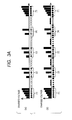
Fig. 3A represents an enlarged view ofFig. 2B ; -
Fig. 3B is a view corresponding toFig. 2C ; -
Fig. 4 is a view representing a method of detecting an optimum charging timing based on an ink particle to which a phase detection charging signal is applied; -
Fig. 5A is a view illustrating a screen of a panel, through which numerical values that relate to the print content are input and set; -
Fig. 5B represents a dot matrix character of the print character "B"; -
Fig. 6A shows timing charts representing the method of detecting the optimum charging timing as related art, indicating a sensor signal and a charging signal; and -
Fig. 6B shows timing charts representing the method of detecting the optimum charging timing as related art, indicating the sensor signal and the charging signal. - An embodiment of the present invention will be described referring to the drawings.
-
Fig. 1 is a block diagram illustrating a general structure of an inkjet recording apparatus according to the present invention. - Referring to
Fig. 1 , areference numeral 1 denotes an MPU (Microprocessing Unit) that controls an inkjet recording apparatus as a whole, 2 denotes a rewritable RAM (Random Access Memory) that temporarily stores data, 3 denotes a ROM (Read Only Memory) that preliminarily stores required program and data, 4 denotes a display device that displays contents to be printed, 5 denotes a panel interface, and 6 denotes a panel with a screen for setting. Areference numeral 7 denotes a timing detection circuit that detects a charging timing, 8 denotes a printing object detection circuit, 9 denotes a printing control circuit that controls printing operations performed by the inkjet recording apparatus, 10 denotes a video RAM that stores video data charged to the ink particle, 11 denotes a charging signal generation circuit that converts the charging data into a printing charging signal or a phase detection charging signal, 12 denotes a nozzle that injects the ink, 13 denotes charging electrodes that charge particles of the ink injected from the nozzle in the form of particulation, 14 denotes a positive polarization electrode, 15 denotes a negative polarization electrode, 16 denotes a gutter that collects the ink particles which are not used for printing, and charged with the phase detection charging signal, 17 denotes a phase detection sensor that detects the phase detection charging signal collected by thegutter gutter 16 to the nozzle again, 19 denotes a sensor that detects the printing object, 20 denotes a conveyor that carries the printing object, 21 denotes the printing object subjected to printing, and 22 denotes a bus line for data transmission. - The printing method will be described hereinafter.
- Upon input of the print information through the
panel 6 via thepanel interface 5, theMPU 1 generates charging data charged to the ink particles in accordance with the print information through the program stored in theROM 3. The data are stored in thevideo RAM 10 via thebus line 22. - When the printing object detection sensor 19 detects the
printing object 21, a printing start instruction is transmitted to theMPU 1 via the printingobject detection circuit 8. TheMPU 1 transmits the print data stored in thevideo RAM 10 to the chargingsignal generation circuit 11. The chargingsignal generation circuit 11 changes the received print data to the printing charging signal. Theprinting control circuit 9 controls the timing for transmission of the printing charging signal to the chargingelectrodes 13 via thebus line 22. If the printing object detection sensor 19 does not detect theprinting object 21, the phase detection video data preliminarily stored in theROM 3 are converted into the phase detection charging signal by the chargingsignal generation circuit 11. The converted signal is transmitted to the chargingelectrodes 13 likewise the printing charging signal. When the printing object detection sensor 19 detects theprinting object 21, the printing charging signal is transmitted. When the printing object detection sensor 19 does not detect theprinting object 21, the phase detection charging signal is transmitted to the chargingelectrodes 13. The ink injected from thenozzle 11 is subjected to particulation within the chargingelectrodes 13, charging, and polarizing during passage in the air through the electric field generated by thepositive polarization electrode 14 and thenegative polarization electrode 15. At that time, the ink particle is polarized in accordance with the charged amount. The highly charged ink particle has a large polarization amount, and the low charged ink particle has a small polarization amount. The ink particle with the highly charged printing charging signal is largely polarized to jump over thegutter 16 and further directed toward theprinting object 21, which is adhered and printed to form a character. - Meanwhile, the ink particle that is not used for printing or charged with the phase detection charging signal with low charged amount cannot jump over the
gutter 16, and will be collected thereby. It is detected by thephase detection sensor 17 as the electric signal, and transmitted to the chargingtiming detection circuit 7 so that the optimum charging timing is detected. - As the optimum charging timing changes from time to time, when the printing charging signal is not generated, the phase detection charging signal is constantly transmitted to the charging
electrodes 13 in order to detect the optimum charging timing for following-up of the change in the optimum charging timing. - As described above, the inkjet recording apparatus detects the optimum charging timing by constantly using the phase detection charging signal, and performs printing using the printing charging signal when the
printing object 21 is detected by the printing object detection sensor 19. - The printing method according to the present invention with respect to the continuous infinite printing conducted by detecting the optimum charging timing will be described.
-
Figs. 2A, 2B and2C represent the printing method which detects the optimum charging timing when printing the continuous characters.Fig. 2A is a timing chart indicating the timing for printing on the printing object.Fig. 2B is an enlarged view of the printing charging signal.Fig. 2C shows a dot matrix of a print character "B". - Referring to
Fig. 2A, (a) denotes an output signal of the printing object detection sensor 19, and (b) denotes a charging signal of the chargingsignal generation circuit 11. When the detection signal is output to the printing object detection sensor 19 as (a) shows, the printing instruction is transmitted, and the printing charging signal rises as (b) shows to start printing. As the printing is continuously performed, the printing charging signal is kept in the rising state until the end of the printing operation. - Each printing pattern of the printing charging signal according to the related art and the present invention will be described referring to
Fig. 2B . -
Fig. 2B represents the printing pattern for continuous printing of the print characters "B" on the printing object. The print character "B" is formed as a dot matrix character asFig. 2C shows. In other words, the character part is formed of 4 (lateral side) x 5 (longitudinal side) dot matrix. The ink particles for character width adjustment are added above the character part as 5 dots for each longitudinal scan. The single longitudinal scan is formed of 5 dots for printing and 5 dots corresponding to the ink particles for character width adjustment. The number of dots for the single longitudinal scan is set to 10.Fig. 2C represents the dot matrix for continuously printing of two print characters "B". Referring toFig. 2B , the print dot pattern of the print character "B" shown inFig. 2C has been mapped for dot printing in chronological order. - The ink particle for character width adjustment, which is not charged is provided between the longitudinal dot scans for width adjustment of the character that is printed by the user. Referring to
Fig. 2C , the ink particles for character width adjustment correspond to 5 dots. If the numerical value is set to be large, the time interval between the longitudinal scans is prolonged, resulting in increased width of the printed character. On the contrary, if the number of the ink particles for character width adjustment is set to be small, the time interval between the longitudinal scans is shortened, resulting in decreased width of the printed character. - Continuous printing of the print character "B" will be described. Referring to
Fig. 2C , the dot matrix character of the print character "B" is formed into 4 (lateral side) x 5 (longitudinal side) dot matrix. The 5 dots of the ink particles for character width adjustment are added to each of the longitudinal scans. Referring toFig. 2C , for the dot printing order, the dot print is performed from the lower side to the upper side of the left line (1) of the dot pattern, from the lower side to the upper side of the line (2), from the lower side to the upper side of the line (3), and finally from the lower side to the upper side of the line (4). Then printing of the single character "B" is completed. - Each printing method according to related art and the present invention will be described referring to
Figs. 3A and 3B corresponding toFigs. 2B and2C , respectively. Referring toFigs. 3A and 3B , the ink particle (black circle) to be printed is designated with the same number as that of the ink particle corresponding to the dot matrix. - The printing method as related art shown in
Fig. 3A(a) will be described. - Referring to
Fig. 3A(a) , the order (1) of the ink particle corresponds to the left line (1) of the dot matrix (Fig. 3B ) of the print character "B". The charged voltage of the ink particle for printing is increased stepwise in order of the black circles (1)(The number in the black circle is referred to as the black circle (1) indicating the ink particle as shown byFigs. 3A and3B ), (2), (3), (4) and (5). As the charged voltage is increased, the polarizing voltage becomes large. The print dot is printed from the lower side to the upper side stepwise at the polarizing electrodes. This makes it possible to print the longitudinal line at the left side of the print character "B". - Then 5 dots (white square marks) of the ink particles for character width adjustment are added. As the aforementioned numerical value for the ink particles for character width adjustment is set to be large, the width of the printed character is increased. On the contrary, as it is set to be small, the character width is decreased.
- The line (2) shown in
Fig. 3B corresponds to the print of the center longitudinal part of the print character "B". The ink particles are directed for printing from the polarizing electrodes in order of the print ink particle as black circle (6), the non-print ink particle (the ink particle not relevant to printing), the print ink particle as black circle (7), the non-print ink particle, and the print ink particle as black circle (8). - Each of the ink particles for printing as black circles (6) and (1), (7) and (3), and (8) and (5) is at the same charged voltage.
- Then 5 dots (white square marks) of the ink particles for character width adjustment are added. The line (3) as shown in
Fig. 3B is printed. - The line (3) shown in
Fig. 3B corresponds to the print of the center longitudinal part of the print character "B". The ink particles are directed for printing from the polarizing electrodes in order of the print ink particle as black circle (9), the non-print ink particle, and the print ink particle as black circle (10), the non-print ink particle, and the print ink particle as black circle (11). Each of the print ink particles as black circles (9) and (6) is at the same charged voltage. Each of the print ink particles as black circles (10) and (7), and (11) and (8) is at the same charged voltage, respectively. - After printing on the line (3) shown in
Fig. 3B ,5 dots (white square marks) of the ink particles for character width adjustment are added to set the character width. - The line (4) shown in
Fig. 3B is printed. The line (4) shown inFig. 3B corresponds to the print of the extending part at the right side of the print character "B". The ink particles are directed from the polarizing electrodes for printing in order of the non-print ink particle, the print ink particle as black circle (12), the non-print ink particle, the print ink particle as black circle (13), and the non-print ink particle. The charged voltage of the print ink particle as black circle (12) is the same as that of the print ink particle as black circle (2) on the line (1). The charged voltage of the print ink particle as black circle (13) is the same as that of the print ink particle as black circle (4) on the line (1). - After printing on the line (4) shown in
Fig. 3B ,5 dots (white square marks) of the ink particles for character width adjustment are added to set the character width. - The above-described printing method is used for printing the print character "B", and the printing is completed.
- When printing of the single print character "B" is completed, subsequent printing of the print character "B" on the next line (1) is started after printing on the line (4) as shown in
Fig. 3B so as to perform continuous printing of the character "B". The aforementioned process is repeatedly performed. - The printing method according to the present invention will be described referring to
Fig. 3B . - The print on the left line (1) of the dot matrix of the print character "B" as shown in
Fig. 3B corresponds to the black circles (1), (2), (3), (4), and (5) for the first print (1) shown inFig. 3A(b) . The charged voltage is increased stepwise in order of the ink particles as black circles (1), (2), (3), (4), and (5) for printing, and the polarizing voltage is increased as well. Polarization is performed stepwise by the polarizing electrodes so as to print from the lower side to the upper side to form the left longitudinal line of the print character "B". - After printing on the line (1) shown in
Fig. 3B ,5 dots (white square marks) of the ink particles for character width adjustment are added. The phase detection charging signal is applied to thecenter 3 dots (black stars) of the 5 dots for detection of the optimum charging timing. - The charged voltage level of the phase detection charging signal is not increased. The charged ink particle cannot jump over the
gutter 6, and collected thereby. It is detected as the electric signal by thephase detection sensor 17, and transmitted to the charging timing detection circuit for detection of the optimum charging timing. - The print on the line (2) shown in
Fig. 3B corresponds to the center longitudinal part of the print character "B". The ink particles are directed from the polarizing electrodes for printing in order of the print ink particle as black circle (6), the non-print ink particle, the print ink particle as black circle (7), the non-print ink particle, and the print ink particle as black circle (8). - After printing on the line (2) shown in
Fig. 3B ,5 dots (white square marks) of the ink particles for character width adjustment are added. The phase detection charging signal is applied to thecenter 3 dots (black stars) of the 5 dots for detection of the optimum charging timing. - The print on the line (3) shown in
Fig. 3B corresponds to the center longitudinal part of the print character "B". The ink particles are directed from the polarizing electrodes for printing in order of the print ink particle as black circle (9), the non-print ink particle, the print ink particle as black circle (10), the non-print ink particle, and the print ink particle as black circle (11). - After printing on the line (3) shown in
Fig. 3B ,5 dots (white square marks) of the ink particles for character width adjustment are added. The phase detection charging signal is applied to thecenter 3 dots (black stars) of the 5 dots for detection of the optimum charging timing. - The print on the line (4) shown in
Fig. 3B corresponds to the extending part at the right side of the print character "B". The ink particles are directed from the polarizing electrodes for printing in order of the non-print ink particle, the print ink particle as black circle (12), the non-print ink particle, the print ink particle as black circle (13), and the non-print ink particle. - After printing as shown in
Fig. 3B ,5 dots (white square marks) of the ink particles for character width adjustment are added. The phase detection charging signal is applied to thecenter 3 dots (black stars) of the 5 dots for detection of the optimum charging timing. - Each of the print ink particles as black circles (1), (6), and (9) is at the same charged voltage. Each of the print ink particles as black circles (3), (7), and (10) is at the same charged voltage. Each of the print ink particles as black circles (5), (8), and (11) is at the same charged voltage. Each of the print ink particles as black circles (2) and (12) is at the same charged voltage. Each of the print ink particles as black circles (4) and (13) has the same charged voltage.
- As described above, the present invention is configured to apply the phase detection charging signal to the ink particles for character width adjustment so as to detect the optimum charging timing.
- The method of detecting the optimum charging timing by applying the phase detection charging signal to the ink particles for character width adjustment will be described referring to
Fig. 4. Fig. 4 is a distribution chart of the charged voltage when thephase detection sensor 17 detects the ink particle charged with the phase detection charging signal, indicating a relationship between the waveform of the charged voltage detected by thephase detection sensor 17 and the optimum charging phase detected by the chargingtiming detection circuit 7. - Referring to
Fig. 4 , the charged voltage is applied by shifting the phase in the particulation cycle of the ink particle for character width adjustment by 1/10 so as to detect the resultant waveform of the charged voltage. The chargingtiming detection circuit 7 makes a comparison between the detected charged voltage and the predetermined threshold voltage in sequence from the 0-phase. The phase at which the detected charged voltage first exceeds the threshold voltage is detected to obtain the optimum charging phase. In the embodiment, the phase is set to 10. However, it is not limited to such value. - As shown in
Fig. 4 , the phase at the highest charged voltage detected to have exceeded the threshold voltage is determined as the optimum charging phase. Referring toFig. 4 , the 4-phase is determined as the optimum charging phase. Application of the phase detection charging signal to the ink particle for character width adjustment allows constant detection of the optimum charging timing even with the infinite printing application for continuous printing. This makes it possible to provide the inkjet recording apparatus that causes no print disorder. If the ink particle for character width adjustment is not set unlike the present invention, the phase detection charging signal cannot be applied to the ink particle for character width adjustment. Therefore, it is effective only in the presence of the ink particle for character width adjustment. - The method which allows the user to set the character width from the
panel 6 will be described referring toFigs. 5A and 5B . -
Fig. 5A illustrates a screen of thepanel 6.Fig. 5B illustrates a dot matrix character of the print character "B". The screen for setting the print content on thepanel 6 is configured to allow input of data with respect to the character height, character width, numerical value of the ink particles for charging timing, character size, print information, number of printing operations continuously performed, and interval between print information data. - The setting screen is a touch panel which allows the user to input the numerical values using
numeric keys 30 at the lower right side of the screen. The inputting of the numerical value is positioned under the control of acursor key 31 for control of an upward, downward, leftward, or rightward movement. The numerical value "99" is set for the character height asFig. 5A shows. However, the numerical value that can be input is in the range from 0 to 99 dots. Actually, height (or size) of the character to be printed on the printing object is determined based on the distance between the inkjet recording apparatus and the printing object. The character height (or size) is determined by adjusting such distance as well. - The character width is set to 5 dots as
Fig. 2C shows. As the numerical value is increased, the time interval between the longitudinal scans is prolonged, thus making the printed character large. On the contrary, as the numerical value is decreased, the time interval between the longitudinal scans is shortened, thus making the printed character width narrow. The numerical value ranging from 0 to 199 dots may be input to the section for setting. - The numerical value of the ink particle to which the phase detection charging signal is applied among those for character width adjustment for setting of the character width is input for the purpose of detecting the charging timing. The ink particle for character width adjustment is used for detection of the charging timing. It is equal to or smaller than the set value of <character width>.
- The character size is set to 4 (lateral side) x 5 (longitudinal side) dot matrix as shown by
Fig. 5A. Fig. 5B illustrates the character "B" by adding 5 dots of the ink particles for character width adjustment above the longitudinal scans (seeFig. 2C ). At the section of the print information, the character to be printed is input and set. In most of cases, alphabets and numerals are set as the print character. At the section of number of printing operations continuously performed, the number of times for printing the character is input and set.Fig. 5A shows that the printing object is long having its length ranging from several to several tens meters, for example, cable, hose or pipe, indicating that the number may be input "infinitely". - The interval between print information data denotes the interval between characters to be printed. Referring to
Fig. 2C , the print character "B" is continuously printed subsequent to the print character "B" with no interval. In this case, the numerical value "000" is set to the section of the interval between print information data. - As described above, the present invention is configured to apply the phase detection charging signal to the ink particle for character width adjustment to allow constant detection of the optimum charging timing for the infinite printing application. This makes it possible to realize the inkjet recording apparatus that causes no print disorder. In the state where the ink particle for character width adjustment is not set, the present invention is not capable of applying the phase detection charging signal to the ink particle, resulting in the print disorder likewise the related art. The embodiment is effective only in the presence of the ink particle for character width adjustment.
- The aforementioned embodiment provides the inkjet recording apparatus capable of detecting the optimum charging timing for infinite printing.
Claims (5)
- An inkjet recording apparatus comprising:an ink particle generation unit that makes a pressurized ink injected from a nozzle that is vibrated at a constant cycle into particles at a constant cycle;a charging unit that applies a charging signal in synchronization with the cycle of particulation based on character information for printing, and electrically charges an ink particle of those subjected to particulation, which corresponds to a dot to be printed;a polarizing unit that polarizes the electrically charged ink particle in a polarizing electric field;a collection unit that allows a gutter to collect the ink particle corresponding to the dot that is not printed; anda character forming unit that forms a character as a dot matrix on a printing object by relatively moving the printing object in a substantially vertical direction to the polarizing direction of the ink particle, wherein a phase detection charging signal is applied to the ink particle that is not used for printing when forming the dot matrix character so as to detect an optimum charging timing in a process of forming the dot matrix character.
- The inkjet recording apparatus according to claim 1, wherein:an ink particle for character width adjustment is added outside the dot matrix character; andthe phase detection charging signal is applied to the ink particle for character width adjustment to detect the optimum charging timing in the process of forming the dot matrix character.
- The inkjet recording apparatus according to claim 2, wherein the optimum charging timing is detected by applying a charged voltage while shifting a phase of the particulation cycle of the ink particle for character width adjustment by 1/N (N: integer), detecting a resultant charged voltage waveform, comparing the charged voltage detected by a charging timing detection circuit with a preliminarily set threshold voltage sequentially from a zero phase, and detecting the phase at which the detected charged voltage first exceeds the threshold voltage.
- The inkjet recording apparatus according to claim 2 or 3, wherein a level of the phase detection charging signal applied to the ink particle for character width adjustment is set to a charged voltage level at which the particle is not capable of jumping over the gutter.
- The inkjet recording apparatus according to any preceding claim, wherein:a panel with a setting screen for setting of a print content is provided; anda character height, a character width, a number of the ink particles for detection of the charging timing, the print information, and a number of printing operations continuously performed are allowed to be input and set on the setting screen of the panel.
Applications Claiming Priority (1)
| Application Number | Priority Date | Filing Date | Title |
|---|---|---|---|
| JP2011179480A JP5759830B2 (en) | 2011-08-19 | 2011-08-19 | Inkjet recording device |
Publications (3)
| Publication Number | Publication Date |
|---|---|
| EP2559557A2 true EP2559557A2 (en) | 2013-02-20 |
| EP2559557A3 EP2559557A3 (en) | 2013-03-06 |
| EP2559557B1 EP2559557B1 (en) | 2014-10-15 |
Family
ID=46603518
Family Applications (1)
| Application Number | Title | Priority Date | Filing Date |
|---|---|---|---|
| EP12005466.3A Active EP2559557B1 (en) | 2011-08-19 | 2012-07-26 | Inkjet recording apparatus |
Country Status (5)
| Country | Link |
|---|---|
| US (1) | US8764145B2 (en) |
| EP (1) | EP2559557B1 (en) |
| JP (1) | JP5759830B2 (en) |
| CN (1) | CN102950890B (en) |
| ES (1) | ES2527394T3 (en) |
Families Citing this family (7)
| Publication number | Priority date | Publication date | Assignee | Title |
|---|---|---|---|---|
| FR2989625B1 (en) | 2012-04-24 | 2015-12-25 | Markem Imaje | PRINTING AN AUTHENTICATION PATTERN WITH A CONTINUOUS INK JET PRINTER |
| JP6114125B2 (en) * | 2013-07-03 | 2017-04-12 | 株式会社日立産機システム | Inkjet recording device |
| CN104924761B (en) * | 2015-06-09 | 2016-06-29 | 厦门英杰华机电科技有限公司 | CIJ ink jet numbering machine print speed control method |
| WO2018038036A1 (en) * | 2016-08-22 | 2018-03-01 | 株式会社日立産機システム | Inkjet recording device and inkjet recording device control method |
| JP7058157B6 (en) * | 2018-03-28 | 2022-05-16 | 株式会社日立産機システム | Inkjet recording device |
| CN110197181B (en) * | 2019-05-31 | 2021-04-30 | 烽火通信科技股份有限公司 | An OCR-based cable character detection method and system |
| CN115648810B (en) * | 2022-10-09 | 2025-05-16 | 青佰科技(珠海)有限公司 | Method for optimizing ink dot modulation value of inkjet printer and computer readable storage medium |
Citations (1)
| Publication number | Priority date | Publication date | Assignee | Title |
|---|---|---|---|---|
| JP2011046139A (en) | 2009-08-28 | 2011-03-10 | Hitachi Industrial Equipment Systems Co Ltd | Inkjet recorder |
Family Cites Families (9)
| Publication number | Priority date | Publication date | Assignee | Title |
|---|---|---|---|---|
| JPS5240167B2 (en) * | 1973-09-26 | 1977-10-11 | ||
| JPS593157B2 (en) * | 1979-02-26 | 1984-01-23 | シャープ株式会社 | Charge detection device for inkjet printers |
| GB2250236B (en) * | 1987-10-30 | 1992-08-19 | Linx Printing Tech D | Ink jet printer |
| GB9626708D0 (en) * | 1996-12-23 | 1997-02-12 | Domino Printing Sciences Plc | Continuous ink jet print head control |
| US7347539B2 (en) * | 2004-06-17 | 2008-03-25 | Videojet Technologies Inc. | System and method for auto-threshold adjustment for phasing |
| DE102006045060A1 (en) * | 2006-09-21 | 2008-04-10 | Kba-Metronic Ag | Method and apparatus for producing variable drop volume ink drops |
| GB0700581D0 (en) * | 2007-01-12 | 2007-02-21 | Domino Printing Sciences Plc | Improvements in or relating to continuous inkjet printers |
| CN101610908B (en) * | 2007-02-23 | 2011-11-09 | 株式会社日立产机系统 | Ink jet recording device |
| JP5202203B2 (en) * | 2008-09-17 | 2013-06-05 | 株式会社日立産機システム | Inkjet recording device |
-
2011
- 2011-08-19 JP JP2011179480A patent/JP5759830B2/en active Active
-
2012
- 2012-07-26 ES ES12005466.3T patent/ES2527394T3/en active Active
- 2012-07-26 EP EP12005466.3A patent/EP2559557B1/en active Active
- 2012-07-31 US US13/562,420 patent/US8764145B2/en active Active
- 2012-08-17 CN CN201210295891.9A patent/CN102950890B/en active Active
Patent Citations (1)
| Publication number | Priority date | Publication date | Assignee | Title |
|---|---|---|---|---|
| JP2011046139A (en) | 2009-08-28 | 2011-03-10 | Hitachi Industrial Equipment Systems Co Ltd | Inkjet recorder |
Also Published As
| Publication number | Publication date |
|---|---|
| JP5759830B2 (en) | 2015-08-05 |
| US20130044149A1 (en) | 2013-02-21 |
| CN102950890A (en) | 2013-03-06 |
| EP2559557B1 (en) | 2014-10-15 |
| JP2013039545A (en) | 2013-02-28 |
| EP2559557A3 (en) | 2013-03-06 |
| ES2527394T3 (en) | 2015-01-23 |
| US8764145B2 (en) | 2014-07-01 |
| CN102950890B (en) | 2015-02-18 |
Similar Documents
| Publication | Publication Date | Title |
|---|---|---|
| US8764145B2 (en) | Inkjet recording apparatus | |
| KR20140060712A (en) | Display device and driving method thereof | |
| CN102470669A (en) | Inkjet recording device and printing head | |
| EP2479711A2 (en) | Recording method and recording apparatus | |
| US20180086052A1 (en) | Ink Jet Recording Apparatus | |
| KR101144615B1 (en) | System and method for auto-threshold adjustment for phasing | |
| CN111032358B (en) | Ink jet recording apparatus and control method thereof | |
| CN107160873B (en) | Spray printing speed lifting method and device | |
| EP4303004B1 (en) | Inkjet printer system | |
| JP6949995B2 (en) | Printer improvements or printer improvements | |
| CN105026160B (en) | inkjet recording device | |
| WO2009128572A1 (en) | Printing system | |
| US11919291B2 (en) | Characteristic table generation system, method of generating characteristic table, and program of generating characteristic table | |
| US11858267B2 (en) | Method for operating a CIJ printer with optical monitoring of printing quality, CIJ printer with optical monitoring of printing quality, and method for teaching-in a CIJ printer with optical monitoring of printing quality | |
| CN109476156B (en) | Inkjet recording apparatus and control method of inkjet recording apparatus | |
| CN102001223B (en) | Ink jet recording device | |
| JP2009179028A (en) | Inkjet recording device | |
| JP2010143122A (en) | Recording apparatus, and recording method | |
| JP2001162807A (en) | Ink jet recording device | |
| JPH0929973A (en) | Ink jet recording device | |
| JP2012126064A (en) | Inkjet recording apparatus | |
| JPS5824277B2 (en) | Inkjet recording device | |
| JPS5923276B2 (en) | Charge-controlled inkjet recording device | |
| JPH06340077A (en) | Character height control device for inkjet printer | |
| JPH06115077A (en) | Inkjet printer print distortion correction device |
Legal Events
| Date | Code | Title | Description |
|---|---|---|---|
| PUAL | Search report despatched |
Free format text: ORIGINAL CODE: 0009013 |
|
| PUAI | Public reference made under article 153(3) epc to a published international application that has entered the european phase |
Free format text: ORIGINAL CODE: 0009012 |
|
| 17P | Request for examination filed |
Effective date: 20121204 |
|
| AK | Designated contracting states |
Kind code of ref document: A2 Designated state(s): AL AT BE BG CH CY CZ DE DK EE ES FI FR GB GR HR HU IE IS IT LI LT LU LV MC MK MT NL NO PL PT RO RS SE SI SK SM TR |
|
| AX | Request for extension of the european patent |
Extension state: BA ME |
|
| AK | Designated contracting states |
Kind code of ref document: A3 Designated state(s): AL AT BE BG CH CY CZ DE DK EE ES FI FR GB GR HR HU IE IS IT LI LT LU LV MC MK MT NL NO PL PT RO RS SE SI SK SM TR |
|
| AX | Request for extension of the european patent |
Extension state: BA ME |
|
| RIC1 | Information provided on ipc code assigned before grant |
Ipc: B41J 2/07 20060101AFI20130131BHEP Ipc: B41J 2/085 20060101ALI20130131BHEP |
|
| RBV | Designated contracting states (corrected) |
Designated state(s): AL AT BE BG CH CY CZ DE DK EE ES FI FR GB GR HR HU IE IS IT LI LT LU LV MC MK MT NL NO PL PT RO RS SE SI SK SM TR |
|
| GRAJ | Information related to disapproval of communication of intention to grant by the applicant or resumption of examination proceedings by the epo deleted |
Free format text: ORIGINAL CODE: EPIDOSDIGR1 |
|
| GRAP | Despatch of communication of intention to grant a patent |
Free format text: ORIGINAL CODE: EPIDOSNIGR1 |
|
| INTG | Intention to grant announced |
Effective date: 20140401 |
|
| INTC | Intention to grant announced (deleted) | ||
| GRAP | Despatch of communication of intention to grant a patent |
Free format text: ORIGINAL CODE: EPIDOSNIGR1 |
|
| INTG | Intention to grant announced |
Effective date: 20140509 |
|
| GRAS | Grant fee paid |
Free format text: ORIGINAL CODE: EPIDOSNIGR3 |
|
| GRAA | (expected) grant |
Free format text: ORIGINAL CODE: 0009210 |
|
| AK | Designated contracting states |
Kind code of ref document: B1 Designated state(s): AL AT BE BG CH CY CZ DE DK EE ES FI FR GB GR HR HU IE IS IT LI LT LU LV MC MK MT NL NO PL PT RO RS SE SI SK SM TR |
|
| REG | Reference to a national code |
Ref country code: CH Ref legal event code: EP Ref country code: GB Ref legal event code: FG4D |
|
| REG | Reference to a national code |
Ref country code: IE Ref legal event code: FG4D |
|
| REG | Reference to a national code |
Ref country code: AT Ref legal event code: REF Ref document number: 691443 Country of ref document: AT Kind code of ref document: T Effective date: 20141115 |
|
| REG | Reference to a national code |
Ref country code: DE Ref legal event code: R096 Ref document number: 602012003367 Country of ref document: DE Effective date: 20141127 |
|
| REG | Reference to a national code |
Ref country code: NL Ref legal event code: T3 |
|
| REG | Reference to a national code |
Ref country code: ES Ref legal event code: FG2A Ref document number: 2527394 Country of ref document: ES Kind code of ref document: T3 Effective date: 20150123 |
|
| REG | Reference to a national code |
Ref country code: AT Ref legal event code: MK05 Ref document number: 691443 Country of ref document: AT Kind code of ref document: T Effective date: 20141015 |
|
| REG | Reference to a national code |
Ref country code: LT Ref legal event code: MG4D |
|
| PG25 | Lapsed in a contracting state [announced via postgrant information from national office to epo] |
Ref country code: LT Free format text: LAPSE BECAUSE OF FAILURE TO SUBMIT A TRANSLATION OF THE DESCRIPTION OR TO PAY THE FEE WITHIN THE PRESCRIBED TIME-LIMIT Effective date: 20141015 Ref country code: FI Free format text: LAPSE BECAUSE OF FAILURE TO SUBMIT A TRANSLATION OF THE DESCRIPTION OR TO PAY THE FEE WITHIN THE PRESCRIBED TIME-LIMIT Effective date: 20141015 Ref country code: NO Free format text: LAPSE BECAUSE OF FAILURE TO SUBMIT A TRANSLATION OF THE DESCRIPTION OR TO PAY THE FEE WITHIN THE PRESCRIBED TIME-LIMIT Effective date: 20150115 Ref country code: IS Free format text: LAPSE BECAUSE OF FAILURE TO SUBMIT A TRANSLATION OF THE DESCRIPTION OR TO PAY THE FEE WITHIN THE PRESCRIBED TIME-LIMIT Effective date: 20150215 Ref country code: PT Free format text: LAPSE BECAUSE OF FAILURE TO SUBMIT A TRANSLATION OF THE DESCRIPTION OR TO PAY THE FEE WITHIN THE PRESCRIBED TIME-LIMIT Effective date: 20150216 |
|
| PG25 | Lapsed in a contracting state [announced via postgrant information from national office to epo] |
Ref country code: PL Free format text: LAPSE BECAUSE OF FAILURE TO SUBMIT A TRANSLATION OF THE DESCRIPTION OR TO PAY THE FEE WITHIN THE PRESCRIBED TIME-LIMIT Effective date: 20141015 Ref country code: SE Free format text: LAPSE BECAUSE OF FAILURE TO SUBMIT A TRANSLATION OF THE DESCRIPTION OR TO PAY THE FEE WITHIN THE PRESCRIBED TIME-LIMIT Effective date: 20141015 Ref country code: RS Free format text: LAPSE BECAUSE OF FAILURE TO SUBMIT A TRANSLATION OF THE DESCRIPTION OR TO PAY THE FEE WITHIN THE PRESCRIBED TIME-LIMIT Effective date: 20141015 Ref country code: GR Free format text: LAPSE BECAUSE OF FAILURE TO SUBMIT A TRANSLATION OF THE DESCRIPTION OR TO PAY THE FEE WITHIN THE PRESCRIBED TIME-LIMIT Effective date: 20150116 Ref country code: CY Free format text: LAPSE BECAUSE OF FAILURE TO SUBMIT A TRANSLATION OF THE DESCRIPTION OR TO PAY THE FEE WITHIN THE PRESCRIBED TIME-LIMIT Effective date: 20141015 Ref country code: AT Free format text: LAPSE BECAUSE OF FAILURE TO SUBMIT A TRANSLATION OF THE DESCRIPTION OR TO PAY THE FEE WITHIN THE PRESCRIBED TIME-LIMIT Effective date: 20141015 Ref country code: HR Free format text: LAPSE BECAUSE OF FAILURE TO SUBMIT A TRANSLATION OF THE DESCRIPTION OR TO PAY THE FEE WITHIN THE PRESCRIBED TIME-LIMIT Effective date: 20141015 Ref country code: LV Free format text: LAPSE BECAUSE OF FAILURE TO SUBMIT A TRANSLATION OF THE DESCRIPTION OR TO PAY THE FEE WITHIN THE PRESCRIBED TIME-LIMIT Effective date: 20141015 |
|
| REG | Reference to a national code |
Ref country code: DE Ref legal event code: R097 Ref document number: 602012003367 Country of ref document: DE |
|
| PG25 | Lapsed in a contracting state [announced via postgrant information from national office to epo] |
Ref country code: CZ Free format text: LAPSE BECAUSE OF FAILURE TO SUBMIT A TRANSLATION OF THE DESCRIPTION OR TO PAY THE FEE WITHIN THE PRESCRIBED TIME-LIMIT Effective date: 20141015 Ref country code: DK Free format text: LAPSE BECAUSE OF FAILURE TO SUBMIT A TRANSLATION OF THE DESCRIPTION OR TO PAY THE FEE WITHIN THE PRESCRIBED TIME-LIMIT Effective date: 20141015 Ref country code: RO Free format text: LAPSE BECAUSE OF FAILURE TO SUBMIT A TRANSLATION OF THE DESCRIPTION OR TO PAY THE FEE WITHIN THE PRESCRIBED TIME-LIMIT Effective date: 20141015 Ref country code: SK Free format text: LAPSE BECAUSE OF FAILURE TO SUBMIT A TRANSLATION OF THE DESCRIPTION OR TO PAY THE FEE WITHIN THE PRESCRIBED TIME-LIMIT Effective date: 20141015 Ref country code: EE Free format text: LAPSE BECAUSE OF FAILURE TO SUBMIT A TRANSLATION OF THE DESCRIPTION OR TO PAY THE FEE WITHIN THE PRESCRIBED TIME-LIMIT Effective date: 20141015 |
|
| PLBE | No opposition filed within time limit |
Free format text: ORIGINAL CODE: 0009261 |
|
| STAA | Information on the status of an ep patent application or granted ep patent |
Free format text: STATUS: NO OPPOSITION FILED WITHIN TIME LIMIT |
|
| 26N | No opposition filed |
Effective date: 20150716 |
|
| PG25 | Lapsed in a contracting state [announced via postgrant information from national office to epo] |
Ref country code: SI Free format text: LAPSE BECAUSE OF FAILURE TO SUBMIT A TRANSLATION OF THE DESCRIPTION OR TO PAY THE FEE WITHIN THE PRESCRIBED TIME-LIMIT Effective date: 20141015 Ref country code: MC Free format text: LAPSE BECAUSE OF FAILURE TO SUBMIT A TRANSLATION OF THE DESCRIPTION OR TO PAY THE FEE WITHIN THE PRESCRIBED TIME-LIMIT Effective date: 20141015 |
|
| REG | Reference to a national code |
Ref country code: CH Ref legal event code: PL |
|
| PG25 | Lapsed in a contracting state [announced via postgrant information from national office to epo] |
Ref country code: LU Free format text: LAPSE BECAUSE OF FAILURE TO SUBMIT A TRANSLATION OF THE DESCRIPTION OR TO PAY THE FEE WITHIN THE PRESCRIBED TIME-LIMIT Effective date: 20150726 |
|
| REG | Reference to a national code |
Ref country code: IE Ref legal event code: MM4A |
|
| PG25 | Lapsed in a contracting state [announced via postgrant information from national office to epo] |
Ref country code: LI Free format text: LAPSE BECAUSE OF NON-PAYMENT OF DUE FEES Effective date: 20150731 Ref country code: CH Free format text: LAPSE BECAUSE OF NON-PAYMENT OF DUE FEES Effective date: 20150731 |
|
| REG | Reference to a national code |
Ref country code: FR Ref legal event code: PLFP Year of fee payment: 5 |
|
| PG25 | Lapsed in a contracting state [announced via postgrant information from national office to epo] |
Ref country code: IE Free format text: LAPSE BECAUSE OF NON-PAYMENT OF DUE FEES Effective date: 20150726 |
|
| PG25 | Lapsed in a contracting state [announced via postgrant information from national office to epo] |
Ref country code: MT Free format text: LAPSE BECAUSE OF FAILURE TO SUBMIT A TRANSLATION OF THE DESCRIPTION OR TO PAY THE FEE WITHIN THE PRESCRIBED TIME-LIMIT Effective date: 20141015 |
|
| PG25 | Lapsed in a contracting state [announced via postgrant information from national office to epo] |
Ref country code: SM Free format text: LAPSE BECAUSE OF FAILURE TO SUBMIT A TRANSLATION OF THE DESCRIPTION OR TO PAY THE FEE WITHIN THE PRESCRIBED TIME-LIMIT Effective date: 20141015 Ref country code: HU Free format text: LAPSE BECAUSE OF FAILURE TO SUBMIT A TRANSLATION OF THE DESCRIPTION OR TO PAY THE FEE WITHIN THE PRESCRIBED TIME-LIMIT; INVALID AB INITIO Effective date: 20120726 Ref country code: BG Free format text: LAPSE BECAUSE OF FAILURE TO SUBMIT A TRANSLATION OF THE DESCRIPTION OR TO PAY THE FEE WITHIN THE PRESCRIBED TIME-LIMIT Effective date: 20141015 |
|
| REG | Reference to a national code |
Ref country code: FR Ref legal event code: PLFP Year of fee payment: 6 |
|
| PG25 | Lapsed in a contracting state [announced via postgrant information from national office to epo] |
Ref country code: TR Free format text: LAPSE BECAUSE OF FAILURE TO SUBMIT A TRANSLATION OF THE DESCRIPTION OR TO PAY THE FEE WITHIN THE PRESCRIBED TIME-LIMIT Effective date: 20141015 |
|
| PG25 | Lapsed in a contracting state [announced via postgrant information from national office to epo] |
Ref country code: BE Free format text: LAPSE BECAUSE OF FAILURE TO SUBMIT A TRANSLATION OF THE DESCRIPTION OR TO PAY THE FEE WITHIN THE PRESCRIBED TIME-LIMIT Effective date: 20141015 |
|
| REG | Reference to a national code |
Ref country code: FR Ref legal event code: PLFP Year of fee payment: 7 |
|
| PG25 | Lapsed in a contracting state [announced via postgrant information from national office to epo] |
Ref country code: MK Free format text: LAPSE BECAUSE OF FAILURE TO SUBMIT A TRANSLATION OF THE DESCRIPTION OR TO PAY THE FEE WITHIN THE PRESCRIBED TIME-LIMIT Effective date: 20141015 |
|
| PG25 | Lapsed in a contracting state [announced via postgrant information from national office to epo] |
Ref country code: AL Free format text: LAPSE BECAUSE OF FAILURE TO SUBMIT A TRANSLATION OF THE DESCRIPTION OR TO PAY THE FEE WITHIN THE PRESCRIBED TIME-LIMIT Effective date: 20141015 |
|
| PGFP | Annual fee paid to national office [announced via postgrant information from national office to epo] |
Ref country code: GB Payment date: 20250605 Year of fee payment: 14 |
|
| PGFP | Annual fee paid to national office [announced via postgrant information from national office to epo] |
Ref country code: NL Payment date: 20250613 Year of fee payment: 14 |
|
| PGFP | Annual fee paid to national office [announced via postgrant information from national office to epo] |
Ref country code: FR Payment date: 20250610 Year of fee payment: 14 |
|
| PGFP | Annual fee paid to national office [announced via postgrant information from national office to epo] |
Ref country code: ES Payment date: 20250801 Year of fee payment: 14 |
|
| PGFP | Annual fee paid to national office [announced via postgrant information from national office to epo] |
Ref country code: DE Payment date: 20250604 Year of fee payment: 14 |
|
| PGFP | Annual fee paid to national office [announced via postgrant information from national office to epo] |
Ref country code: IT Payment date: 20250623 Year of fee payment: 14 |