EP2559524A1 - Robot control system and robot control method - Google Patents
Robot control system and robot control method Download PDFInfo
- Publication number
- EP2559524A1 EP2559524A1 EP12156107A EP12156107A EP2559524A1 EP 2559524 A1 EP2559524 A1 EP 2559524A1 EP 12156107 A EP12156107 A EP 12156107A EP 12156107 A EP12156107 A EP 12156107A EP 2559524 A1 EP2559524 A1 EP 2559524A1
- Authority
- EP
- European Patent Office
- Prior art keywords
- robot
- virtual
- robots
- axes
- control system
- Prior art date
- Legal status (The legal status is an assumption and is not a legal conclusion. Google has not performed a legal analysis and makes no representation as to the accuracy of the status listed.)
- Withdrawn
Links
Images



Classifications
-
- B—PERFORMING OPERATIONS; TRANSPORTING
- B25—HAND TOOLS; PORTABLE POWER-DRIVEN TOOLS; MANIPULATORS
- B25J—MANIPULATORS; CHAMBERS PROVIDED WITH MANIPULATION DEVICES
- B25J9/00—Program-controlled manipulators
- B25J9/06—Program-controlled manipulators characterised by multi-articulated arms
-
- B—PERFORMING OPERATIONS; TRANSPORTING
- B25—HAND TOOLS; PORTABLE POWER-DRIVEN TOOLS; MANIPULATORS
- B25J—MANIPULATORS; CHAMBERS PROVIDED WITH MANIPULATION DEVICES
- B25J9/00—Program-controlled manipulators
- B25J9/16—Program controls
- B25J9/1679—Program controls characterised by the tasks executed
- B25J9/1682—Dual arm manipulator; Coordination of several manipulators
-
- B—PERFORMING OPERATIONS; TRANSPORTING
- B25—HAND TOOLS; PORTABLE POWER-DRIVEN TOOLS; MANIPULATORS
- B25J—MANIPULATORS; CHAMBERS PROVIDED WITH MANIPULATION DEVICES
- B25J5/00—Manipulators mounted on wheels or on carriages
- B25J5/02—Manipulators mounted on wheels or on carriages travelling along a guideway
-
- B—PERFORMING OPERATIONS; TRANSPORTING
- B25—HAND TOOLS; PORTABLE POWER-DRIVEN TOOLS; MANIPULATORS
- B25J—MANIPULATORS; CHAMBERS PROVIDED WITH MANIPULATION DEVICES
- B25J9/00—Program-controlled manipulators
- B25J9/0084—Program-controlled manipulators comprising a plurality of manipulators
- B25J9/0087—Dual arms
-
- B—PERFORMING OPERATIONS; TRANSPORTING
- B25—HAND TOOLS; PORTABLE POWER-DRIVEN TOOLS; MANIPULATORS
- B25J—MANIPULATORS; CHAMBERS PROVIDED WITH MANIPULATION DEVICES
- B25J9/00—Program-controlled manipulators
- B25J9/16—Program controls
Definitions
- the embodiment discussed herein is directed to a robot control system and a robot control method.
- a conventional robot control system that controls a multi-axis robot has been known.
- the robot control system performs interference prevention control by which a multi-axis robot prevents interfering with surrounding obstacles on the basis of axis position information detected by a position detector such as an encoder.
- the robot control system has been known as disclosed in, for example, Japanese Laid-open Patent Publication No. 2009-90403 .
- a two-arm robot that has one body and a pair of multi-axis robots acting as two arms has further been known.
- the robot control system performs interference prevention control on the basis of individual position detection for each arm, that is to say, for each multi-axis robot.
- the robot control system When the body of the two-arm robot is not fixed to a fixed surface such as a floor but is fixed to movable external axes such as pivot axes or travelling axes, the robot control system performs individual interference prevention control on the external axes.
- the robot control system performs individual interference prevention control on multi-axis robots and external axes as described above, the robot control system has a problem in that the overall process of the system is easily complicated.
- a behavior of a multi-axis robot normally requires certainty. Therefore, it is preferable to avoid complication that has an influence on the whole system in order to guarantee the certainty.
- the problem is also caused due to the entire control of robots that are connected to each other, in addition to the interference prevention control of a two-arm robot.
- An aspect of an embodiment has been achieved in view of the above problem, and an object of the embodiment is to provide a robot control system and a robot control method that are used for easily and certainly controlling a plurality of robots that is connected to each other.
- a robot control system includes a plurality of robots, at least one external axis, and converters.
- the robots perform axis behaviors.
- the external axis is a movable axis that is shared by the robots and connects the robots each other.
- Each of the converters assumes a virtual robot formed by connecting all external axes to one robot and converts acquisition values for positions of the robot and the external axes acquired for the virtual robot into conversion values indicating absolute positions in a predetermined normal coordinate system.
- a plurality of robots connected to each other can be easily and certainly controlled.
- FIG. 1 is a diagram illustrating a configuration example of a robot control system according to an embodiment
- FIG. 2A is a pattern diagram illustrating axes used in the robot control system according to the embodiment.
- FIG. 2B is a diagram illustrating virtual robots assumed in the robot control system according to the embodiment.
- FIG. 3 is a block diagram illustrating the configuration of the robot control system according to the embodiment.
- FIG. 4A is a diagram illustrating connection relation of the robot control system according to the embodiment.
- FIG. 4B is a diagram illustrating a connection configuration example of the robot control system according to the embodiment.
- FIG. 5 is a flowchart illustrating a routine that is performed by the robot control system according to the embodiment
- FIG. 6A is a diagram illustrating the brief of a general interference prevention control technique.
- FIG. 6B is a pattern diagram illustrating axes used in a conventional interference prevention control technique.
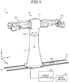
- FIG. 1 is a diagram illustrating a configuration example of a robot control system 1 according to the embodiment.
- a three-dimensional rectangular coordinate system that includes Z-axis of which the positive direction is a vertically upward direction is illustrated in FIG. 1 .
- the rectangular coordinate system can be employed in other drawings that are used for the following explanations.
- the robot control system 1 includes a robot 10, a robot controller 20, and an input device 30.
- the robot 10 includes a robot R1, a robot R2, a body 11, and a base 12.
- the robot 10 is a so-called two-arm robot that includes the robot R1 and the robot R2 as two arms.
- the robot R1 and the robot R2 are multi-axis robots (seven-axis robots in FIG. 1 ) and have end effectors (not illustrated) provided in both terminated movable parts.
- the body 11 supports the robot R1 and the robot R2.
- the base 12 supports the body 11 in such a manner that the body 11 can revolve around a pivot axis AZ (see a double-headed arrow 100 of FIG. 1 ).
- the base 12 is placed on a rail part 13.
- the base 12 includes a not-illustrated traveling mechanism and travels on the placed rail part 13 along a travelling axis AY (see a double-headed arrow 200 of FIG. 1 ).
- the pivot axis AZ and the travelling axis AY may be external axes that are shared by the robot R1 and the robot R2.
- the robot controller 20 is a controller that performs the entire control of the robot 10.
- the robot controller 20 mainly performs interference prevention control.
- a configuration example of the robot controller 20 is described below with reference to FIG. 3 .
- the robot controller 20 is connected to the robot 10 via a communication network such as a wired LAN (Local Area Network) or a wireless LAN.
- a communication network such as a wired LAN (Local Area Network) or a wireless LAN.
- the input device 30 is a device that receives an operation from an operator.
- the input device 30 is further connected to the robot controller 20 via a communication network such as a wired LAN or a wireless LAN.
- the operator performs teaching on the robot 10 and sets an operating area of the robot 10 via the input device 30.
- FIG. 6A is a diagram illustrating the brief of a general interference prevention control technique.
- FIG. 6B is a pattern diagram illustrating axes used in a conventional interference prevention control technique.
- a robot 10' illustrated in FIGs. 6A and 6B has the same axis configuration as that of the robot 10 of the robot control system 1 according to the embodiment.
- FIG. 6A a situation before a behavior of the robot 10' is illustrated on the left side of a page space and a situation after the behavior of the robot 10' is illustrated on the right side of the page space. It is assumed that the robot 10' is in a predetermined operating area 500 before the behavior.
- the general interference prevention control technique determines whether the robot R1 or the robot R2 goes out of the operating area 500 in response to the movement directive.
- the movement directive is additionally modified in such a manner that the robot R1 or the robot R2 enters the operating area 500, for example.
- a preliminary check process for the movement directive.
- the conventional interference prevention control technique acquires the positions of the robot R1 and the robot R2 of the robot 10' by using separate coordinate systems.
- the positions (specifically, rotation angles etc.) of the pivot axis AZ illustrated in FIG. 1 are also acquired by using separate coordinate systems.
- Parts surrounded by closed dotted curves of FIG. 6B indicate that the positions of the robot R1, the robot R2, and the pivot axis AZ are individually acquired. Although it is not illustrated, this point is similarly applied to the travelling axis AY.
- the conventional interference prevention control technique is difficult to grasp mutual positions of the robot R1, the robot R2, and the pivot axis AZ.
- an interference prevention control process is easily complicated, an operator who performs teaching on the robot 10' requires a high skill, for example.
- the robot control system 1 acquires the positions of the robot R1, the robot R2, and the external axes shared by these robots by using a predetermined common normal coordinate system.
- FIG. 2A is a pattern diagram illustrating axes used in the robot control system 1 according to the embodiment.
- FIG. 2B is a diagram illustrating virtual robots assumed in the robot control system 1 according to the embodiment.
- the robot control system 1 treats the pivot axis AZ and the travelling axis AY (see FIG. 1 ) that are external axes as a robot R3 and a robot R4 in addition to the robot R1 and the robot R2.
- a part surrounded by a closed dotted curve of FIG. 2A indicates that the positions of the robots R1 to R4 are acquired by using, for example, a base coordinate system (see XYZ coordinates of FIG. 2A ) of the robot R4 as a normal coordinate system.
- the robot control system 1 assumes virtual robots of which each is formed by connecting all the external axes to one multi-axis robot in a row.
- a virtual robot is formed by connecting the robot R3 and the robot R4 to the robot R1 in a row.
- a virtual robot is formed by connecting the robot R3 and the robot R4 to the robot R2 in a row.
- the robot control system 1 acquires positions of axes (or, robots) that constitute each of the virtual robots. Then, the robot control system 1 converts acquisition values on the positions acquired for each virtual robot into conversion values that indicate absolute positions in the predetermined normal coordinate system.
- the predetermined normal coordinate system employs a base coordinate system in which the robot R1 or the robot R2 is a start end and an external axis is positioned to its termination end in a row.
- the base coordinate system of the robot R4 is used as a normal coordinate system.
- positions, in the predetermined normal coordinate system, of axes that constitute each virtual robot are shared by at least each the virtual robot.
- each of the robot R1 and the robot R2 can obtain position information of the robot R3 and the robot R4.
- the robot control system 1 finally integrates position information for the virtual robots and grasps absolute positions of all the axes of the robot 10.
- the robot control system 1 because a complicated process caused by the control of separate coordinate systems can be avoided, a two-arm robot that has multi-axis robots connected to each other can be controlled easily and certainly.
- a base coordinate system in which an external axis is positioned to the termination end of a virtual robot is employed as a normal coordinate system.
- the normal coordinate system may be always fixed to a world coordinate system that is set on a ground surface or a working floor.
- FIG. 3 is a block diagram illustrating the configuration of the robot control system 1 according to the embodiment.
- FIG. 3 Only components required for the explanation of the robot control system 1 are illustrated in FIG. 3 and thus the description on general components is omitted. Moreover, components illustrated in FIG. 3 are logical blocks that are abstracted on the basis of only their functions and the like. Therefore, the hardware configuration and the like of the robot control system 1 are not limited to this.
- the robot control system 1 includes the robots R1 to R4 and the robot controller 20.
- the description of the input device 30 illustrated in FIG. 1 is omitted.
- the robot R1 includes an encoder enR1 that is a position detector.
- the robot R2 includes an encoder enR2
- the robot R3 includes an encoder enR3
- the robot R4 includes an encoder enR4.
- each of the robot R1 and the robot R2 actually has encoders that correspond to axes of a multi-axis robot. However, only the encoder enR1 and the encoder enR2 that detect a predetermined representative position are illustrated herein.
- the robot controller 20 includes a control unit 21 and a storage unit 22.
- the control unit 21 includes a virtual robot converter 21a-1 corresponding to the robot R1, a virtual robot converter 21a-2 corresponding to the robot R2, an integration unit 21b, and a servo control unit 21c.
- the storage unit 22 stores configuration definition information 22a.
- the virtual robot converter 21a-1 is a processing unit that assumes a virtual robot formed by connecting the robot R3 and the robot R4 to the robot R1 and acquires the positions of the robot R1, the robot R3, and the robot R4 that are the axes of the virtual robot.
- the virtual robot converter 21a-1 acquires an output value of the encoder enR1 as an acquisition value indicating the position of the robot R1. Similarly, the virtual robot converter 21a-1 further acquires an output value of the encoder enR3 as an acquisition value indicating the position of the robot R3 and an output value of the encoder enR4 as an acquisition value indicating the position of the robot R4.
- the virtual robot converter 21a-1 converts the acquisition values into conversion values that indicate absolute positions in the predetermined normal coordinate system.
- the conversion can use a so-called forward kinematics calculation.
- the conversion values that are converted are output to the integration unit 21b to be described below.
- the virtual robot converter 21a-1 determines a predetermined normal coordinate system and the like, with reference to definition information on the configuration of the virtual robot previously registered in the configuration definition information 22a of the storage unit 22.
- the definition information includes, for example, connection relation information that indicates which of the robot R1, the robot R3, and the robot R4 is positioned at a higher side.
- the virtual robot converter 21a-1 together performs the subsequent check process for the movement directive on the basis of the conversion values.
- the virtual robot converter 21a-2 is a processing unit that assumes a virtual robot formed by connecting the robot R3 and the robot R4 to the robot R2 and acquires the positions of the robot R2, the robot R3, and the robot R4 that are the axes of the virtual robot.
- the number of virtual robot converters is two of the virtual robot converter 21a-1 and the virtual robot converter 21a-2
- the number of virtual robot converters may be arbitrary in accordance with the number of virtual robots to be assumed.
- the integration unit 21b is a processing unit that integrates the positions of all the axes of the robot 10 (see FIG. 1 ) in the predetermined normal coordinate system, on the basis of the conversion values that indicate the positions of the axes of the virtual robots input from the virtual robot converter 21a-1 and the virtual robot converter 21a-2.
- the integration unit 21b together performs the preliminary check process for the movement directive on the basis of the integrated positions of the axes of the robot 10.
- the integration unit 21b outputs a movement directive to the servo control unit 21c after performing the preliminary check process.
- the integration unit 21b can further monitor the movement directive to check interference of the robot R1 and the robot R2.
- the servo control unit 21c is a processing unit that outputs a control signal for a servo (not illustrated) of each of the robots R1 to R4 to the servo on the basis of the movement directive input from the integration unit 21b.
- the servos drive the respective robots R1 to R4 on the basis of the respective control signals output from the servo control unit 21c.
- the storage unit 22 is a storage device such as for example a nonvolatile memory and a hard disk drive and stores therein the configuration definition information 22a. Because the configuration definition information 22a is explained in detail, the description is omitted herein.
- FIG. 4A is a diagram illustrating connection relation of the robot control system 1 according to the embodiment.
- FIG. 4B is a diagram illustrating a connection configuration example of the robot control system 1 according to the embodiment.
- a virtual robot conversion unit 210a-1 illustrated in FIGs. 4A and 4B is a component corresponding to the virtual robot converter 21a-1 illustrated in FIG. 3 .
- a virtual robot conversion unit 210a-2 is a component corresponding to the virtual robot converter 21a-2 illustrated in FIG. 3 .
- a main CPU board 210b is a component corresponding to the integration unit 21b illustrated in FIG. 3 .
- a servo control board 210c-1 and a servo control board 210c-2 are components corresponding to the servo control unit 21c illustrated in FIG. 3 .
- the servo control board 210c-1 illustrated in FIGs. 4A and 4B drives the axes of the rabot R1 and the robot R3.
- the servo control board 210c-2 drives the axes of the robot R2 and the robot R4.
- the encoder enR1 is connected to the servo control board 210c-1 and the virtual robot conversion unit 210a-1 (see “O" symbol of FIG. 4A ).
- the encoder enR2 is connected to the servo control board 210c-2 and the virtual robot conversion unit 210a-2.
- the encoder enR3 is connected to the servo control board 210c-1, the virtual robot conversion unit 210a-1, and the virtual robot conversion unit 210a-2.
- the encoder enR4 is connected to the virtual robot conversion unit 210a-1, the servo control board 210c-2, and the virtual robot conversion unit 210a-2.
- the encoder enR3 of the robot R3 that is an external axis is connected to both the virtual robot conversion unit 210a-1 and the virtual robot conversion unit 210a-2.
- the encoder enR4 of the robot R4 that is an external axis is connected to both the virtual robot conversion unit 210a-1 and the virtual robot conversion unit 210a-2.
- a unit (any of the virtual robot conversion unit 210a-1 and the virtual robot conversion unit 210a-2) that assumes one virtual robot is connected to all the encoders associated with external axes.
- FIG. 4B A connection configuration example assuming the connection relation illustrated in FIG. 4A is illustrated in FIG. 4B .
- the encoder enR1 is connected to the servo control board 210c-1 via the input and output ports of the virtual robot conversion unit 210a-1.
- the encoder enR2 is connected to the servo control board 210c-2 via the input and output ports of the virtual robot conversion unit 210a-2.
- the encoder enR3 is connected to the servo control board 210c-1 via the virtual robot conversion unit 210a-2 and the virtual robot conversion unit 210a-1 in a row.
- the encoder enR4 is connected to the servo control board 210c-2 via the virtual robot conversion unit 210a-1 and the virtual robot conversion unit 210a-2 in a row.
- FIG. 4B is only an example of a connection configuration and thus does not limit an actual connection configuration. Therefore, the configuration of FIG. 4B can be appropriately changed in accordance with a physical specification and the like of each unit of the robot control system 1.
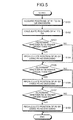
- FIG. 5 is a flowchart illustrating a routine that is performed by the robot control system 1 according to the embodiment.
- a routine of a position computation process performed by the robot control system 1 is illustrated in FIG. 5 .
- the position computation process can be performed by any of the virtual robot converter 21a-1, the virtual robot converter 21a-2, and the integration unit 21b, which are described above.
- the robot control system 1 acquires positions of the robots R1 to R4 via the encoders enR1 to enR4 (Step S101).
- the robot control system 1 calculates the positions of the robots R1 to R4 on the basis of acquisition values on the acquired positions of the robots R1 to R4 (Step S102).
- the calculation is performed by converting the acquisition values that are output values of the encoders enR1 to enR4 into position values in the respective coordinate systems.
- the robot control system 1 determines whether the robot R3 is connected to a higher order than the robot R4 (Step S103). When it is determined that the robot R3 is connected to a high order than the robot R4 (Step S103: Yes), the robot control system 1 recalculates the position of the robot R3 by using the base coordinate system of the robot R4 as a standard (Step S104).
- Step S103 determines whether the determination condition of Step S103 is not satisfied (Step S103: No).
- the robot control system 1 determines whether the robot R1 is connected to a high order than the robot R3 (Step S105). When it is determined that the robot R1 is connected to a high order than the robot R3 (Step S105: Yes), the robot control system 1 recalculates the position of the robot R1 by using the base coordinate system of the robot R3 as a standard (Step S106).
- Step S104 If the position of the robot R3 is already recalculated at Step S104, the recalculation of the position of the robot R1 at Step S106 is consequently performed by using the base coordinate system of the robot R4 as a standard. This point is similarly applied to Step S108 to be described below.
- Step S105 determines whether the determination condition of Step S105 is not satisfied (Step S105: No).
- the robot control system 1 determines whether the robot R2 is connected to a high order than the robot R3 (Step S107). When it is determined that the robot R2 is connected to a high order than the robot R3 (Step S107: Yes), the robot control system 1 recalculates the position of the robot R2 by using the base coordinate system of the robot R3 as a standard (Step S108) and terminates the process.
- Step S107 No
- the robot control system 1 terminates the process.
- a multi-axis robot may be a single-axis robot, or a two-arm robot may be a multi-arm robot that has three or more arms.
- the robot control system according to the embodiment can be applied to a plurality of robots connected to each other via external axes.
- the robot control system includes: a plurality of robots; at least one external axis that is a movable axis shared by the robots; and converters.
- Each of the converters assumes a virtual robot formed by connecting all external axes to one robot and converts acquisition values on positions of the robot and the external axes acquired for the virtual robot into conversion values indicating absolute positions in a predetermined normal coordinate system.
- the plurality of robots connected to each other can be easily and certainly controlled.
- positions in a predetermined normal coordinate system of robots and external axes are calculated on the basis of acquisition values acquired via encoders
- the embodiment can be further applied to "postures” based on "positions".
- the "postures” may be expressed with "directions”.
Landscapes
- Engineering & Computer Science (AREA)
- Robotics (AREA)
- Mechanical Engineering (AREA)
- Manipulator (AREA)
- Numerical Control (AREA)
Abstract
A robot control system (1) according to an aspect of an embodiment includes a plurality of robots (R1, R2), at least one external axis (R3, R4), and converters (21a-1, 21a-2). The robots (R1, R2) perform axis behaviors. The external axes (R3, R4) are a movable axis shared by the robots (R1, R2) and are mutually connected to the robots (R1, R2). Each of the converters (21a-1, 21a-2) assumes a virtual robot formed by connecting all the external axes (R3, R4) to the one robot (R1, R2) and converts acquisition values on positions of the robot (R1, R2) and the external axes (R3, R4) acquired for the virtual robot into conversion values indicating absolute positions in a predetermined normal coordinate system.
Description
- The embodiment discussed herein is directed to a robot control system and a robot control method.
- A conventional robot control system that controls a multi-axis robot has been known. The robot control system performs interference prevention control by which a multi-axis robot prevents interfering with surrounding obstacles on the basis of axis position information detected by a position detector such as an encoder. The robot control system has been known as disclosed in, for example, Japanese Laid-open Patent Publication No.
2009-90403 - A two-arm robot that has one body and a pair of multi-axis robots acting as two arms has further been known. In the case of the two-arm robot, the robot control system performs interference prevention control on the basis of individual position detection for each arm, that is to say, for each multi-axis robot.
- When the body of the two-arm robot is not fixed to a fixed surface such as a floor but is fixed to movable external axes such as pivot axes or travelling axes, the robot control system performs individual interference prevention control on the external axes.
- However, because the conventional robot control system performs individual interference prevention control on multi-axis robots and external axes as described above, the robot control system has a problem in that the overall process of the system is easily complicated.
- A behavior of a multi-axis robot normally requires certainty. Therefore, it is preferable to avoid complication that has an influence on the whole system in order to guarantee the certainty.
- The problem is also caused due to the entire control of robots that are connected to each other, in addition to the interference prevention control of a two-arm robot.
- An aspect of an embodiment has been achieved in view of the above problem, and an object of the embodiment is to provide a robot control system and a robot control method that are used for easily and certainly controlling a plurality of robots that is connected to each other.
- A robot control system according to an aspect of an embodiment includes a plurality of robots, at least one external axis, and converters. The robots perform axis behaviors. The external axis is a movable axis that is shared by the robots and connects the robots each other. Each of the converters assumes a virtual robot formed by connecting all external axes to one robot and converts acquisition values for positions of the robot and the external axes acquired for the virtual robot into conversion values indicating absolute positions in a predetermined normal coordinate system.
- According to an aspect of an embodiment, a plurality of robots connected to each other can be easily and certainly controlled.
- A more complete appreciation of the invention and many of the attendant advantages thereof will be readily obtained as the same becomes better understood by reference to the following detailed description when considered in connection with the accompanying drawings, wherein:
-
FIG. 1 is a diagram illustrating a configuration example of a robot control system according to an embodiment; -
FIG. 2A is a pattern diagram illustrating axes used in the robot control system according to the embodiment; -
FIG. 2B is a diagram illustrating virtual robots assumed in the robot control system according to the embodiment; -
FIG. 3 is a block diagram illustrating the configuration of the robot control system according to the embodiment; -
FIG. 4A is a diagram illustrating connection relation of the robot control system according to the embodiment; -
FIG. 4B is a diagram illustrating a connection configuration example of the robot control system according to the embodiment; -
FIG. 5 is a flowchart illustrating a routine that is performed by the robot control system according to the embodiment; -
FIG. 6A is a diagram illustrating the brief of a general interference prevention control technique; and -
FIG. 6B is a pattern diagram illustrating axes used in a conventional interference prevention control technique. - Hereinafter, a robot control system and a robot control method according to an embodiment of the present disclosure will be described in detail. In addition, the embodiment disclosed below is not intended to limit the present invention.
-
FIG. 1 is a diagram illustrating a configuration example of arobot control system 1 according to the embodiment. In order to make an explanation understandable, a three-dimensional rectangular coordinate system that includes Z-axis of which the positive direction is a vertically upward direction is illustrated inFIG. 1 . The rectangular coordinate system can be employed in other drawings that are used for the following explanations. - As illustrated in
FIG. 1 , therobot control system 1 includes arobot 10, a robot controller 20, and an input device 30. - The
robot 10 includes a robot R1, a robot R2, abody 11, and abase 12. Herein, as illustrated inFIG. 1 , therobot 10 is a so-called two-arm robot that includes the robot R1 and the robot R2 as two arms. - The robot R1 and the robot R2 are multi-axis robots (seven-axis robots in
FIG. 1 ) and have end effectors (not illustrated) provided in both terminated movable parts. - As illustrated in
FIG. 1 , thebody 11 supports the robot R1 and the robot R2. Moreover, thebase 12 supports thebody 11 in such a manner that thebody 11 can revolve around a pivot axis AZ (see a double-headed arrow 100 ofFIG. 1 ). Furthermore, thebase 12 is placed on arail part 13. - The
base 12 includes a not-illustrated traveling mechanism and travels on the placedrail part 13 along a travelling axis AY (see a double-headed arrow 200 ofFIG. 1 ). Herein, the pivot axis AZ and the travelling axis AY may be external axes that are shared by the robot R1 and the robot R2. - The robot controller 20 is a controller that performs the entire control of the
robot 10. Hereinafter, it will be explained that the robot controller 20 mainly performs interference prevention control. Moreover, a configuration example of the robot controller 20 is described below with reference toFIG. 3 . - The robot controller 20 is connected to the
robot 10 via a communication network such as a wired LAN (Local Area Network) or a wireless LAN. - The input device 30 is a device that receives an operation from an operator. The input device 30 is further connected to the robot controller 20 via a communication network such as a wired LAN or a wireless LAN. The operator performs teaching on the
robot 10 and sets an operating area of therobot 10 via the input device 30. - Herein, an interference prevention control technique will be explained with reference to
FIGs. 6A and 6B. FIG. 6A is a diagram illustrating the brief of a general interference prevention control technique.FIG. 6B is a pattern diagram illustrating axes used in a conventional interference prevention control technique. - A robot 10' illustrated in
FIGs. 6A and 6B has the same axis configuration as that of therobot 10 of therobot control system 1 according to the embodiment. - In
FIG. 6A , a situation before a behavior of the robot 10' is illustrated on the left side of a page space and a situation after the behavior of the robot 10' is illustrated on the right side of the page space. It is assumed that the robot 10' is in apredetermined operating area 500 before the behavior. - As illustrated in
FIG. 6A , when a movement directive is given to the robot 10', the general interference prevention control technique determines whether the robot R1 or the robot R2 goes out of theoperating area 500 in response to the movement directive. - Herein, when it is determined that the robot R1 or the robot R2 goes out of the
operating area 500 as illustrated in the right side of the page space ofFIG. 6A , the movement directive is additionally modified in such a manner that the robot R1 or the robot R2 enters theoperating area 500, for example. Hereinafter, such a process is referred to as a "preliminary check process" for the movement directive. - In consideration of a time lag and an error of the movement directive, it is determined whether the robot R1 and the robot R2 after the behavior are within the
operating area 500. Such a determination is performed on the basis of actual measurement values measured by position detectors such as encoders included in the robot R1 and the robot R2. Hereinafter, such a process is referred to as a "subsequent check process" for the movement directive. - Meanwhile, as illustrated in
FIG. 6B , the conventional interference prevention control technique acquires the positions of the robot R1 and the robot R2 of the robot 10' by using separate coordinate systems. - Similarly, the positions (specifically, rotation angles etc.) of the pivot axis AZ illustrated in
FIG. 1 are also acquired by using separate coordinate systems. - Parts surrounded by closed dotted curves of
FIG. 6B indicate that the positions of the robot R1, the robot R2, and the pivot axis AZ are individually acquired. Although it is not illustrated, this point is similarly applied to the travelling axis AY. - Therefore, the conventional interference prevention control technique is difficult to grasp mutual positions of the robot R1, the robot R2, and the pivot axis AZ. In other words, because an interference prevention control process is easily complicated, an operator who performs teaching on the robot 10' requires a high skill, for example.
- Therefore, it is assumed that the
robot control system 1 according to the embodiment acquires the positions of the robot R1, the robot R2, and the external axes shared by these robots by using a predetermined common normal coordinate system. - The details of this point are explained with reference to
FIGs. 2A and 2B. FIG. 2A is a pattern diagram illustrating axes used in therobot control system 1 according to the embodiment.FIG. 2B is a diagram illustrating virtual robots assumed in therobot control system 1 according to the embodiment. - As illustrated in
FIG. 2A , it is assumed that therobot control system 1 according to the embodiment treats the pivot axis AZ and the travelling axis AY (seeFIG. 1 ) that are external axes as a robot R3 and a robot R4 in addition to the robot R1 and the robot R2. - It is assumed that the positions of the robots R1 to R4 are acquired by using a predetermined common normal coordinate system. Herein, a part surrounded by a closed dotted curve of
FIG. 2A indicates that the positions of the robots R1 to R4 are acquired by using, for example, a base coordinate system (see XYZ coordinates ofFIG. 2A ) of the robot R4 as a normal coordinate system. - Specifically, the
robot control system 1 according to the embodiment assumes virtual robots of which each is formed by connecting all the external axes to one multi-axis robot in a row. For example, in the case of the robot R1, as illustrated by a part surrounded by aclosed curve 300 ofFIG. 2B , a virtual robot is formed by connecting the robot R3 and the robot R4 to the robot R1 in a row. - In the case of the robot R2, as illustrated by a part surrounded by a
closed curve 400 ofFIG. 2B , a virtual robot is formed by connecting the robot R3 and the robot R4 to the robot R2 in a row. - The
robot control system 1 according to the embodiment acquires positions of axes (or, robots) that constitute each of the virtual robots. Then, therobot control system 1 converts acquisition values on the positions acquired for each virtual robot into conversion values that indicate absolute positions in the predetermined normal coordinate system. - At this time, the predetermined normal coordinate system employs a base coordinate system in which the robot R1 or the robot R2 is a start end and an external axis is positioned to its termination end in a row. In other words, because the robot R4 is positioned to the termination end in the example illustrated in
FIG. 2B , the base coordinate system of the robot R4 is used as a normal coordinate system. - As a result, positions, in the predetermined normal coordinate system, of axes that constitute each virtual robot are shared by at least each the virtual robot. In other words, each of the robot R1 and the robot R2 can obtain position information of the robot R3 and the robot R4.
- Then, the
robot control system 1 according to the embodiment finally integrates position information for the virtual robots and grasps absolute positions of all the axes of therobot 10. In other words, because a complicated process caused by the control of separate coordinate systems can be avoided, a two-arm robot that has multi-axis robots connected to each other can be controlled easily and certainly. - It has been explained in the example described above that a base coordinate system in which an external axis is positioned to the termination end of a virtual robot is employed as a normal coordinate system. However, the normal coordinate system may be always fixed to a world coordinate system that is set on a ground surface or a working floor.
- Next, a configuration example of the
robot control system 1 according to the embodiment will be explained in detail with reference toFIG. 3. FIG. 3 is a block diagram illustrating the configuration of therobot control system 1 according to the embodiment. - Only components required for the explanation of the
robot control system 1 are illustrated inFIG. 3 and thus the description on general components is omitted. Moreover, components illustrated inFIG. 3 are logical blocks that are abstracted on the basis of only their functions and the like. Therefore, the hardware configuration and the like of therobot control system 1 are not limited to this. - As illustrated in
FIG. 3 , therobot control system 1 includes the robots R1 to R4 and the robot controller 20. Herein, the description of the input device 30 illustrated inFIG. 1 is omitted. - The robot R1 includes an encoder enR1 that is a position detector. Similarly, the robot R2 includes an encoder enR2, the robot R3 includes an encoder enR3, and the robot R4 includes an encoder enR4.
- Because the robot R1 and the robot R2 are multi-axis robots, each of the robot R1 and the robot R2 actually has encoders that correspond to axes of a multi-axis robot. However, only the encoder enR1 and the encoder enR2 that detect a predetermined representative position are illustrated herein.
- The robot controller 20 includes a control unit 21 and a storage unit 22. The control unit 21 includes a
virtual robot converter 21a-1 corresponding to the robot R1, avirtual robot converter 21a-2 corresponding to the robot R2, an integration unit 21b, and a servo control unit 21c. The storage unit 22 storesconfiguration definition information 22a. - The
virtual robot converter 21a-1 is a processing unit that assumes a virtual robot formed by connecting the robot R3 and the robot R4 to the robot R1 and acquires the positions of the robot R1, the robot R3, and the robot R4 that are the axes of the virtual robot. - Specifically, the
virtual robot converter 21a-1 acquires an output value of the encoder enR1 as an acquisition value indicating the position of the robot R1. Similarly, thevirtual robot converter 21a-1 further acquires an output value of the encoder enR3 as an acquisition value indicating the position of the robot R3 and an output value of the encoder enR4 as an acquisition value indicating the position of the robot R4. - The
virtual robot converter 21a-1 converts the acquisition values into conversion values that indicate absolute positions in the predetermined normal coordinate system. The conversion can use a so-called forward kinematics calculation. Then, the conversion values that are converted are output to the integration unit 21b to be described below. - The
virtual robot converter 21a-1 determines a predetermined normal coordinate system and the like, with reference to definition information on the configuration of the virtual robot previously registered in theconfiguration definition information 22a of the storage unit 22. The definition information includes, for example, connection relation information that indicates which of the robot R1, the robot R3, and the robot R4 is positioned at a higher side. - The
virtual robot converter 21a-1 together performs the subsequent check process for the movement directive on the basis of the conversion values. - The
virtual robot converter 21a-2 is a processing unit that assumes a virtual robot formed by connecting the robot R3 and the robot R4 to the robot R2 and acquires the positions of the robot R2, the robot R3, and the robot R4 that are the axes of the virtual robot. - Because the process of the
virtual robot converter 21a-2 is similar to the process of thevirtual robot converter 21a-1 except that the robot R1 is replaced by the robot R2, the description is omitted herein. - Although it is illustrated in
FIG. 3 that the number of virtual robot converters is two of thevirtual robot converter 21a-1 and thevirtual robot converter 21a-2, the number of virtual robot converters may be arbitrary in accordance with the number of virtual robots to be assumed. - The integration unit 21b is a processing unit that integrates the positions of all the axes of the robot 10 (see
FIG. 1 ) in the predetermined normal coordinate system, on the basis of the conversion values that indicate the positions of the axes of the virtual robots input from thevirtual robot converter 21a-1 and thevirtual robot converter 21a-2. - The integration unit 21b together performs the preliminary check process for the movement directive on the basis of the integrated positions of the axes of the
robot 10. - The integration unit 21b outputs a movement directive to the servo control unit 21c after performing the preliminary check process. The integration unit 21b can further monitor the movement directive to check interference of the robot R1 and the robot R2.
- The servo control unit 21c is a processing unit that outputs a control signal for a servo (not illustrated) of each of the robots R1 to R4 to the servo on the basis of the movement directive input from the integration unit 21b.
- Then, the servos drive the respective robots R1 to R4 on the basis of the respective control signals output from the servo control unit 21c.
- The storage unit 22 is a storage device such as for example a nonvolatile memory and a hard disk drive and stores therein the
configuration definition information 22a. Because theconfiguration definition information 22a is explained in detail, the description is omitted herein. - Next, a connection configuration of the
robot control system 1 according to the embodiment is explained with reference toFIGs. 4A and 4B. FIG. 4A is a diagram illustrating connection relation of therobot control system 1 according to the embodiment.FIG. 4B is a diagram illustrating a connection configuration example of therobot control system 1 according to the embodiment. - A virtual
robot conversion unit 210a-1 illustrated inFIGs. 4A and 4B is a component corresponding to thevirtual robot converter 21a-1 illustrated inFIG. 3 . Moreover, a virtualrobot conversion unit 210a-2 is a component corresponding to thevirtual robot converter 21a-2 illustrated inFIG. 3 . - Similarly, a
main CPU board 210b is a component corresponding to the integration unit 21b illustrated inFIG. 3 . Moreover, aservo control board 210c-1 and aservo control board 210c-2 are components corresponding to the servo control unit 21c illustrated inFIG. 3 . - Herein, it is assumed that the
servo control board 210c-1 illustrated inFIGs. 4A and 4B drives the axes of the rabot R1 and the robot R3. Moreover, it is assumed that theservo control board 210c-2 drives the axes of the robot R2 and the robot R4. - In this case, as illustrated in
FIG. 4A , the encoder enR1 is connected to theservo control board 210c-1 and the virtualrobot conversion unit 210a-1 (see "O" symbol ofFIG. 4A ). Moreover, the encoder enR2 is connected to theservo control board 210c-2 and the virtualrobot conversion unit 210a-2. - As illustrated in
FIG. 4A , the encoder enR3 is connected to theservo control board 210c-1, the virtualrobot conversion unit 210a-1, and the virtualrobot conversion unit 210a-2. Moreover, the encoder enR4 is connected to the virtualrobot conversion unit 210a-1, theservo control board 210c-2, and the virtualrobot conversion unit 210a-2. - In other words, the encoder enR3 of the robot R3 that is an external axis is connected to both the virtual
robot conversion unit 210a-1 and the virtualrobot conversion unit 210a-2. Similarly, the encoder enR4 of the robot R4 that is an external axis is connected to both the virtualrobot conversion unit 210a-1 and the virtualrobot conversion unit 210a-2. - In other words, a unit (any of the virtual
robot conversion unit 210a-1 and the virtualrobot conversion unit 210a-2) that assumes one virtual robot is connected to all the encoders associated with external axes. - A connection configuration example assuming the connection relation illustrated in
FIG. 4A is illustrated inFIG. 4B . For example, as illustrated inFIG. 4B , the encoder enR1 is connected to theservo control board 210c-1 via the input and output ports of the virtualrobot conversion unit 210a-1. - Similarly, the encoder enR2 is connected to the
servo control board 210c-2 via the input and output ports of the virtualrobot conversion unit 210a-2. - For example, the encoder enR3 is connected to the
servo control board 210c-1 via the virtualrobot conversion unit 210a-2 and the virtualrobot conversion unit 210a-1 in a row. - Similarly, the encoder enR4 is connected to the
servo control board 210c-2 via the virtualrobot conversion unit 210a-1 and the virtualrobot conversion unit 210a-2 in a row. - The configuration of
FIG. 4B is only an example of a connection configuration and thus does not limit an actual connection configuration. Therefore, the configuration ofFIG. 4B can be appropriately changed in accordance with a physical specification and the like of each unit of therobot control system 1. - Next, a routine performed by the
robot control system 1 according to the embodiment is explained with reference toFIG. 5. FIG. 5 is a flowchart illustrating a routine that is performed by therobot control system 1 according to the embodiment. - A routine of a position computation process performed by the
robot control system 1 is illustrated inFIG. 5 . The position computation process can be performed by any of thevirtual robot converter 21a-1, thevirtual robot converter 21a-2, and the integration unit 21b, which are described above. - As illustrated in
FIG. 5 , therobot control system 1 acquires positions of the robots R1 to R4 via the encoders enR1 to enR4 (Step S101). - Then, the
robot control system 1 calculates the positions of the robots R1 to R4 on the basis of acquisition values on the acquired positions of the robots R1 to R4 (Step S102). Herein, the calculation is performed by converting the acquisition values that are output values of the encoders enR1 to enR4 into position values in the respective coordinate systems. - Then, the
robot control system 1 determines whether the robot R3 is connected to a higher order than the robot R4 (Step S103). When it is determined that the robot R3 is connected to a high order than the robot R4 (Step S103: Yes), therobot control system 1 recalculates the position of the robot R3 by using the base coordinate system of the robot R4 as a standard (Step S104). - On the other hand, when the determination condition of Step S103 is not satisfied (Step S103: No), the
robot control system 1 moves the process control to Step S105. - Next, the
robot control system 1 determines whether the robot R1 is connected to a high order than the robot R3 (Step S105). When it is determined that the robot R1 is connected to a high order than the robot R3 (Step S105: Yes), therobot control system 1 recalculates the position of the robot R1 by using the base coordinate system of the robot R3 as a standard (Step S106). - If the position of the robot R3 is already recalculated at Step S104, the recalculation of the position of the robot R1 at Step S106 is consequently performed by using the base coordinate system of the robot R4 as a standard. This point is similarly applied to Step S108 to be described below.
- On the other hand, when the determination condition of Step S105 is not satisfied (Step S105: No), the
robot control system 1 moves the process control to Step S107. - Next, the
robot control system 1 determines whether the robot R2 is connected to a high order than the robot R3 (Step S107). When it is determined that the robot R2 is connected to a high order than the robot R3 (Step S107: Yes), therobot control system 1 recalculates the position of the robot R2 by using the base coordinate system of the robot R3 as a standard (Step S108) and terminates the process. - On the other hand, when the determination condition of Step S107 is not satisfied (Step S107: No), the
robot control system 1 terminates the process. - Meanwhile, a two-arm robot that has two multi-axis robots as two arms has been explained till now. However, the configuration of the robot is not limited to this. For example, a multi-axis robot may be a single-axis robot, or a two-arm robot may be a multi-arm robot that has three or more arms.
- In other words, the robot control system according to the embodiment can be applied to a plurality of robots connected to each other via external axes.
- As described above, the robot control system according to the embodiment includes: a plurality of robots; at least one external axis that is a movable axis shared by the robots; and converters. Each of the converters assumes a virtual robot formed by connecting all external axes to one robot and converts acquisition values on positions of the robot and the external axes acquired for the virtual robot into conversion values indicating absolute positions in a predetermined normal coordinate system.
- Therefore, according to the robot control system according to the embodiment, the plurality of robots connected to each other can be easily and certainly controlled.
- Although it has been mainly explained that "positions" in a predetermined normal coordinate system of robots and external axes are calculated on the basis of acquisition values acquired via encoders, the embodiment can be further applied to "postures" based on "positions". Herein, the "postures" may be expressed with "directions".
Claims (5)
- A robot control system (1) comprising:a plurality of robots (R1, R2);at least one external axis (R3, R4) that is a movable axis shared by the robots (R1, R2);converters (21a-1, 21a-2) of which each assumes a virtual robot formed by connecting all the external axes (R3, R4) to the one robot (R1, R2) and converts acquisition values on positions of the robot (R1, R2) and the external axes (R3, R4) acquired for the virtual robot into conversion values indicating absolute positions in a predetermined normal coordinate system.
- The robot control system (1) according to claim 1, wherein the converter (21a-1, 21a-2) determines whether the robot (R1, R2) and the external axes (R3, R4) are within a predetermined operating area on the basis of the conversion values.
- The robot control system (1) according to claim 1, further comprising position detectors that are respectively provided in association with the external axes (R3, R4) and axes of the robots (R1, R2) and detects positions of the external axes (R3, R4) and the axes of the robots (R1, R2),
wherein
one of the converters (21a-1, 21a-2) is connected to all the position detectors that are associated with the external axes (R3, R4). - The robot control system (1) according to claim 1, wherein the converter (21a-1, 21a-2) assumes the virtual robot, in which the robot (R1, R2) is a start end and the external axes (R3, R4) are connected to the start end in a row, and employs a base coordinate system, of which a base is the external axis (R3, R4) located at a termination end of the row, as the normal coordinate system.
- A robot control method comprising:assuming virtual robots of which each includes a robot (R1, R2) and external axes (R3, R4) that are movable axes connected to the robot (R1, R2); andconverting acquisition values on positions of the robot (R1, R2) and the external axes (R3, R4) acquired for each the virtual robot into conversion values indicating absolute positions in a predetermined normal coordinate system.
Applications Claiming Priority (1)
| Application Number | Priority Date | Filing Date | Title |
|---|---|---|---|
| JP2011177897A JP5488549B2 (en) | 2011-08-16 | 2011-08-16 | Robot control system and robot control method |
Publications (1)
| Publication Number | Publication Date |
|---|---|
| EP2559524A1 true EP2559524A1 (en) | 2013-02-20 |
Family
ID=45656135
Family Applications (1)
| Application Number | Title | Priority Date | Filing Date |
|---|---|---|---|
| EP12156107A Withdrawn EP2559524A1 (en) | 2011-08-16 | 2012-02-20 | Robot control system and robot control method |
Country Status (5)
| Country | Link |
|---|---|
| US (1) | US9108315B2 (en) |
| EP (1) | EP2559524A1 (en) |
| JP (1) | JP5488549B2 (en) |
| KR (1) | KR20130019333A (en) |
| CN (1) | CN102950597B (en) |
Cited By (1)
| Publication number | Priority date | Publication date | Assignee | Title |
|---|---|---|---|---|
| CN110000769A (en) * | 2019-05-23 | 2019-07-12 | 深圳航天科技创新研究院 | Both arms cooperation robot |
Families Citing this family (6)
| Publication number | Priority date | Publication date | Assignee | Title |
|---|---|---|---|---|
| USD723599S1 (en) * | 2013-04-15 | 2015-03-03 | Inos Automationssoftware Gmbh | Measuring instrument |
| CN103529847A (en) * | 2013-10-22 | 2014-01-22 | 南京邮电大学 | Multi-robot pollution control method based on Voronoi diagrams |
| EP2993693B1 (en) | 2014-03-31 | 2018-06-06 | Nippon Micrometal Corporation | Bonding wire for use with semiconductor devices and method for manufacturing said bonding wire |
| JP6384195B2 (en) * | 2014-08-20 | 2018-09-05 | 株式会社安川電機 | Robot system and robot teaching method |
| CN106826773A (en) * | 2017-03-31 | 2017-06-13 | 祝星晨 | A kind of tow-armed robot mounting seat of electromechanical integration |
| WO2024019987A1 (en) * | 2022-07-18 | 2024-01-25 | Dexterity, Inc. | Modular force/torque sensor system |
Citations (2)
| Publication number | Priority date | Publication date | Assignee | Title |
|---|---|---|---|---|
| JP2009090403A (en) | 2007-10-05 | 2009-04-30 | Fanuc Ltd | Robot movement range setting device |
| KR20090044130A (en) * | 2007-10-31 | 2009-05-07 | 한국기계연구원 | Collision Control Method for Two-arm Robot System |
Family Cites Families (9)
| Publication number | Priority date | Publication date | Assignee | Title |
|---|---|---|---|---|
| JPS57113111A (en) * | 1980-12-30 | 1982-07-14 | Fanuc Ltd | Robot control system |
| JPH11347983A (en) * | 1998-06-11 | 1999-12-21 | Meidensha Corp | Manipulator action limiting device |
| CN2623741Y (en) * | 2003-03-05 | 2004-07-07 | 邓根焕 | Clothes rail with grooves for clothes drying cabinet |
| JP4217125B2 (en) * | 2003-07-30 | 2009-01-28 | トヨタ自動車株式会社 | Production system |
| CN1304178C (en) * | 2004-05-24 | 2007-03-14 | 熊勇刚 | Method for testing collision between joint of robot with multiple mechanical arm |
| JP4440178B2 (en) * | 2005-07-25 | 2010-03-24 | 東京エレクトロン株式会社 | Substrate transfer device |
| JP4823767B2 (en) * | 2006-05-31 | 2011-11-24 | 日立建機株式会社 | Double-arm work machine |
| JP2008100292A (en) | 2006-10-17 | 2008-05-01 | Toshiba Mach Co Ltd | Robot system |
| JP4477029B2 (en) * | 2007-03-27 | 2010-06-09 | 株式会社東芝 | robot |
-
2011
- 2011-08-16 JP JP2011177897A patent/JP5488549B2/en not_active Expired - Fee Related
- 2011-12-12 US US13/316,562 patent/US9108315B2/en not_active Expired - Fee Related
-
2012
- 2012-02-01 KR KR1020120010333A patent/KR20130019333A/en not_active Ceased
- 2012-02-16 CN CN201210035411.5A patent/CN102950597B/en not_active Expired - Fee Related
- 2012-02-20 EP EP12156107A patent/EP2559524A1/en not_active Withdrawn
Patent Citations (2)
| Publication number | Priority date | Publication date | Assignee | Title |
|---|---|---|---|---|
| JP2009090403A (en) | 2007-10-05 | 2009-04-30 | Fanuc Ltd | Robot movement range setting device |
| KR20090044130A (en) * | 2007-10-31 | 2009-05-07 | 한국기계연구원 | Collision Control Method for Two-arm Robot System |
Non-Patent Citations (2)
| Title |
|---|
| CHANHUN PARK ET AL: "Dual arm robot manipulator and its easy teaching system", ASSEMBLY AND MANUFACTURING, 2009. ISAM 2009. IEEE INTERNATIONAL SYMPOSIUM ON, IEEE, PISCATAWAY, NJ, USA, 17 November 2009 (2009-11-17), pages 242 - 247, XP031598708, ISBN: 978-1-4244-4627-8 * |
| KIMBERLY FARRELL ET AL: "Modeling Dual-Arm Coordination for Posture: An Optimization-Based Approach", 1 January 2005 (2005-01-01), XP055027583, Retrieved from the Internet <URL:http://www.loomingsuspicions.com/docs/dual-arm.pdf> [retrieved on 20120521] * |
Cited By (1)
| Publication number | Priority date | Publication date | Assignee | Title |
|---|---|---|---|---|
| CN110000769A (en) * | 2019-05-23 | 2019-07-12 | 深圳航天科技创新研究院 | Both arms cooperation robot |
Also Published As
| Publication number | Publication date |
|---|---|
| JP5488549B2 (en) | 2014-05-14 |
| US20130046408A1 (en) | 2013-02-21 |
| US9108315B2 (en) | 2015-08-18 |
| CN102950597A (en) | 2013-03-06 |
| KR20130019333A (en) | 2013-02-26 |
| JP2013039635A (en) | 2013-02-28 |
| CN102950597B (en) | 2016-04-06 |
Similar Documents
| Publication | Publication Date | Title |
|---|---|---|
| US9108315B2 (en) | Robot control system and robot control method | |
| JP5743495B2 (en) | Robot controller | |
| US10213916B2 (en) | Control apparatus and robot system | |
| US20140277731A1 (en) | Robot picking system, control device, and method of manufacturing a workpiece | |
| US10384347B2 (en) | Robot control device, robot, and simulation device | |
| JP2019093481A (en) | Robot system and robot system control method | |
| US20170277167A1 (en) | Robot system, robot control device, and robot | |
| US20150343641A1 (en) | Robot, control method of robot, and control device of robot | |
| CN113768626B (en) | Surgical robot control method, computer device and surgical robot system | |
| CN114454180B (en) | Motion control method and device for mobile robot and mobile robot | |
| JP2017074647A (en) | Robot system comprising function for calculating position and orientation of sensor | |
| US20170028548A1 (en) | Robot control device and robot control method | |
| US20170066137A1 (en) | Control device, robot, and robot system | |
| US20220168895A1 (en) | Collision detection | |
| JP6696341B2 (en) | Control method | |
| JP2021024019A (en) | Trajectory generation device | |
| CN117412840A (en) | Collaborative robot with collision detection function and collision detection method of collaborative robot | |
| JP2022500260A (en) | Controls for robotic devices, robotic devices, methods, computer programs and machine-readable storage media | |
| JP2017177321A (en) | Control device and robot system | |
| KR20210027455A (en) | System and method for detection and correction of robot payload position | |
| KR20230032498A (en) | Multi robot system for construction and controlling method of the same | |
| TWI851147B (en) | Machine posture inspection method and machine posture inspection system | |
| CN115990882B (en) | Safety control method and system for robot | |
| WO2025022824A1 (en) | Robot control system, method for controlling same, and program | |
| JP7384005B2 (en) | Control method and robot system |
Legal Events
| Date | Code | Title | Description |
|---|---|---|---|
| PUAI | Public reference made under article 153(3) epc to a published international application that has entered the european phase |
Free format text: ORIGINAL CODE: 0009012 |
|
| 17P | Request for examination filed |
Effective date: 20121025 |
|
| AK | Designated contracting states |
Kind code of ref document: A1 Designated state(s): AL AT BE BG CH CY CZ DE DK EE ES FI FR GB GR HR HU IE IS IT LI LT LU LV MC MK MT NL NO PL PT RO RS SE SI SK SM TR |
|
| AX | Request for extension of the european patent |
Extension state: BA ME |
|
| STAA | Information on the status of an ep patent application or granted ep patent |
Free format text: STATUS: THE APPLICATION HAS BEEN WITHDRAWN |
|
| 18W | Application withdrawn |
Effective date: 20160718 |