EP2559383A1 - Stethoscope head with adjustable audio frequency - Google Patents
Stethoscope head with adjustable audio frequency Download PDFInfo
- Publication number
- EP2559383A1 EP2559383A1 EP10849643A EP10849643A EP2559383A1 EP 2559383 A1 EP2559383 A1 EP 2559383A1 EP 10849643 A EP10849643 A EP 10849643A EP 10849643 A EP10849643 A EP 10849643A EP 2559383 A1 EP2559383 A1 EP 2559383A1
- Authority
- EP
- European Patent Office
- Prior art keywords
- ring
- diaphragm
- annular
- annular groove
- head body
- Prior art date
- Legal status (The legal status is an assumption and is not a legal conclusion. Google has not performed a legal analysis and makes no representation as to the accuracy of the status listed.)
- Granted
Links
Images



Classifications
-
- A—HUMAN NECESSITIES
- A61—MEDICAL OR VETERINARY SCIENCE; HYGIENE
- A61B—DIAGNOSIS; SURGERY; IDENTIFICATION
- A61B7/00—Instruments for auscultation
- A61B7/02—Stethoscopes
-
- A—HUMAN NECESSITIES
- A61—MEDICAL OR VETERINARY SCIENCE; HYGIENE
- A61B—DIAGNOSIS; SURGERY; IDENTIFICATION
- A61B7/00—Instruments for auscultation
- A61B7/02—Stethoscopes
- A61B7/04—Electric stethoscopes
Definitions
- the invention relates to a medical equipment assembly and, more particularly, to a stethoscope assembly.
- a conventional stethoscope includes a head 1, a rubber tube 2, ear tubes 3 and earpieces 4.
- a user listens to multiple sounds with different audio frequencies, he or she usually needs to change the volume of a sound collecting chamber of the head 1. Namely, the user can change the volume of the sound collecting chamber when he or she needs to listen to both a high frequency sound and a low frequency sound.
- a diaphragm 12 is disposed at a head body 14 and is fastened via a fastener 11.
- the fastener 11 is an annular rubber ring and wraps an annular step 121 of the diaphragm 12 and the head body 14 to fasten the diaphragm 12 to the head body 14.
- the conventional stethoscope When the conventional stethoscope is used, if the user would like to switch the listening frequency from a low frequency sound to a high frequency sound, he or she only needs to press the diaphragm 12 to make the diaphragm 12 contact the annular protrusion 145. At that moment, a ⁇ angle of the diaphragm changes. However, since a lower surface 128 of the annular step is fastened to a platform 149 of the head body by the fastener 11, it is difficult to change the ⁇ angle. The user needs to spend more effort to press the head body 14 to change the ⁇ angle. As the result, the user may feel uncomfortable.
- every user has his or her own audibility, preference and auscultation habit, but he or she cannot adjust the sound intensity of the conventional stethoscope, and can only use the predetermined frequency.
- the conventional dual-frequency stethoscope head is not convenient to assemble, and it needs a skilled person to assemble carefully to ensure the hearing effect.
- An object of the invention is to provide a stethoscope head in which the assembling is easy, the sound effect is adjustable, sounds with different sound intensities can be heard, and can be adjusted continuously.
- the invention provides a stethoscope head with adjustable audio frequency including a head body, a diaphragm and a fastener.
- the diaphragm is provided with an annular step and a footing.
- the diaphragm is disposed on a sound collecting surface at the front side of the head body and is fastened to the head body by the fastener.
- the outer marginal part of the front side of the head body is provided with the annular step, and a screw thread is provided on a step surface of the annular step.
- An annular groove is provided at the sound collecting surface at the inner side surface of the annular step, and the inner side surface of the annular groove and the bottom surface of the annular groove form an obtuse angle ⁇ , and 100° ⁇ 145 °.
- the diaphragm footing is disposed in the annular groove and contacts the inner side surface of the annular groove.
- the fastener includes a ring A and a ring B whose upper surfaces are located at the same horizontal plane.
- the ring B is place in the ring A and the external diameter of the ring B is the same as the internal diameter of the ring A.
- An inner wall of the ring A is provided with a screw thread which matches with the screw thread on the step surface.
- the screw pitches of the two matching screw threads are small pitch which ranges from 0.25mm to 0.75mm. This is benefit for improving the accuracy of the audio frequency.
- the ⁇ angle is an obtuse angle
- the force is decomposed of a horizontal force and a vertical force when applied to the inner side surface of the annular groove.
- the upward reacting force applied to the diaphragm is the vertical force provided by the inner side surface of the annular groove.
- the horizontal reacting force applied to the diaphragm is the horizontal force provided by the inner side surface of the annular groove, and the force changes the â angle between the diaphragm footing and the annular step.
- the contacting surfaces between the diaphragm and the annular groove of the head body are the bottom surface of the diaphragm and the inner side surface of the footing of the diaphragm.
- the diameter of the transverse section of the annular groove increases from top to bottom.
- the â angle increases, the diaphragm footing moves downwardly along the inner side surface of the annular groove.
- the sound collecting surface at the inner side of the annular groove is provided with an annular protrusion, and a washer is disposed on the annular protrusion or a recess is disposed at the annular protrusion.
- the recess is also provided with a washer, and the washer can improve the sealing ability of the sound collecting chamber to achieve better listening effect.
- a sealing ring is disposed between the annular step and the ring A, and the sealing ring can avoid the sound leakage between the bottom surface of the ring A of the fastener and the contacting surface of the annular step when listening to a low frequency sound.
- the sealing ring has high elasticity, and it exerts a reacting force to the ring of the fastener 11 when the lower surface of the fastener 11 is pressed.
- the stableness during usage is achieved by improving the uneasy-to-shift ability when a non-initiative force is applied to the fastener 11, and the uneasy-to-shift ability is achieved by increasing the friction force between the inner screw thread of the ring and the screw thread of the step surface of the annular ring.
- the back side of the head body is provided with graduation
- the outer surface of the ring A is provided with an arrow.
- the conventional stethoscope provides only audio frequencies in two fixed bands, but the stethoscope in the invention can provide frequencies in two main bands and frequencies in multiple secondary bands. The user can adjust the crisp of the frequency according to his or her auscultation habit.
- the conventional stethoscope requires high skill in assembling and changing components, and it need skilled persons to assemble. During the assembling, it is easy to lose the dual-frequency function unintentionally. However, the stethoscope in the invention is easy to assemble, and the assembling process does not need the help of skilled persons.
- the multi-frequency function can be achieved after simple assembling process.
- the pressure force is usually 9.23 N to 11.12 N.
- the same frequency effect can be obtained by applying only 5.39 N to 7.23 N pressure force.
- the diaphragm is easy to get fatigue, and generally it can be used for 25000 to 30000 times. In the invention, the diaphragm is not easy to get fatigue, and generally it can be used form 50000 to 60000 times.
- FIG. 1 is a schematic diagram showing a conventional stethoscope.
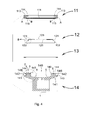
- FIG. 2 is a schematic diagram showing a stethoscope head in the conventional stethoscope.
- FIG. 3 is an exploded diagram of FIG. 2 .
- FIG. 4 is an exploded diagram showing a stethoscope head in an embodiment of the invention.
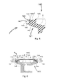
- FIG. 5 is an enlarged schematic diagram showing a section in the head body 14 in FIG. 4 .
- FIG. 6 is a first schematic diagram showing the stethoscope head in an embodiment of the invention.
- FIG. 7 is an enlarged schematic diagram showing a section of the head body 14 in FIG. 6 .
- FIG. 8 is a second schematic diagram showing the stethoscope head in an embodiment of the invention.
- FIG. 9 is a schematic diagram showing the fastener in an embodiment of the invention.
- FIG. 10 is a partial diagram showing the diaphragm 12 in FIG. 4 .
- FIG. 11 is a back view of the stethoscope head in an embodiment of the invention.
- FIG. 12 is a partial diagram showing the annular protrusion 145 of the head body 14 and the annular groove 1451 disposed on the annular protrusion 145.
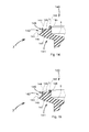
- FIG. 13 is a first partial diagram showing the annular protrusion 145 of the head body 14 and the washer 160 disposed on the annular protrusion 145.
- FIG. 14 is a second partial diagram showing the annular protrusion 145 of the head body 14 and the washer 160 disposed on the annular protrusion 145.
- FIG. 15 is a third partial diagram showing the annular protrusion 145 of the head body 14 and the washer 160 disposed on the annular protrusion 145.
- Embodiment 1 is illustrated along with FIG. 4 , FIG. 5 , FIG. 6 , FIG. 7 , FIG. 9 and FIG. 10 .
- a stethoscope head with adjustable audio frequency includes a head body 14, a diaphragm 12 and a fastener 11.
- the outer marginal part of the front side 140 of the head body is provided with an annular step 142, and a step surface 146 of the annular step 142 is provided with a screw thread.
- a sound collecting surface 5 at the inner side of the annular step 142 is provided with an annular groove 144, and an inner side surface 148 and a bottom surface 147 of the annular groove 144 form an obtuse angle ⁇ .
- the fastener 11 includes a ring A and a ring B, an upper surface 113 of the ring A and an upper surface 114 of the ring B are in the same horizontal plane.
- the ring B is disposed inside the ring A and the external diameter of the ring B is the same as the internal diameter of the ring A.
- the inner wall 115 of the ring A is provided with a screw thread 111 to match with the screw thread 143 of the step surface.
- the diaphragm 12 is provided with an annular step 121 and a footing 122.
- the footing 122 of the diaphragm 12 is disposed in the annular groove 144.
- the bottom surface 127 of the inner surface of the footing 122 of the diaphragm 12 contacts the inner side surface 148 of the annular groove 144, and the diaphragm 12 is fastened to the head body 14 via the fastener 11.
- the inner side surface 148 and the bottom surface 147 of the annular groove 144 form an obtuse angle ⁇ , and 100° ⁇ 145 °.
- annular protrusion 145 is further disposed on the sound collecting surface 5 at the inner side of the annular groove 144.
- the inner side surface 148 of the annular groove 144 and the bottom surface 147 of the annular groove form an obtuse angle ⁇ , and 100° ⁇ 145 °.
- a washer 160 is further provided on the annular protrusion 145. Adding the washer 160 can improve the sealing ability of the sound collecting chamber and improve the sound effect.
- the ⁇ angle between the inner side surface 148 of the annular groove 144 and the bottom surface 147 of the annular groove 144 is, the pressure that makes the lower surface 126 of the diaphragm contact the annular protrusion 145 (namely the required pressure for obtaining another audio frequency) is less.
- the pressure is too small, during obtaining the other audio frequency, the upper surface 125 of the diaphragm does not totally contact the auscultation area, which affects the auscultation.
- the general proper pressure for changing the frequency is larger than 5N and less than 10N. Under proper pressure scope, the stethoscope can obtain preferable frequency-change effect and the auscultation area is not easy to be uncomfortable due to pressure.
- the angle ⁇ formed between the inner side surface 148 of the annular groove 144 and the bottom surface 147 of the annular groove ranges above or equal to 100 ° and less than 145 °.
- the audio frequency attenuation is less.
- the angle ⁇ formed between the inner side surface 148 of the annular groove 144 and the bottom surface 147 of the annular groove is preferable above or equal to 100° and less than 145°
- the thickness of the diaphragm footing 0.6mm, and the hardness of the rubber is 60° shore hardness.
- the elasticity is measured in the method and parameter herein below: the upper surface of a square rubber block is applied by 19.6 N vertical force, and the downward and vertical deformation distance is 1.21 mm.
- the annular protrusion 145 is also provided with an annular groove 1451, and the annular groove 1451 is disposed on the annular protrusion 145 to make the amount of the surface butting the lower surface 126 of the diaphragm increased to two annular surfaces.
- a washer 160 is further disposed in the recess of the annular groove 1451, and when the head body 14 is pressed, the diaphragm footing 122 moves downwardly in the annular groove 144 until the lower surface 126 of the diaphragm butts the washer 160 of the annular protrusion 145.
- the washer 160 is provided with two annular edges, when the head body 14 is pressed, the two annular edges butt the lower surface 126 of the diaphragm and form the sound collecting chamber 6.
- the contacting surfaces of the washer 160 and the lower surface 126 of the diaphragm are increased, the sealing effect of the sound collecting chamber 6 is improved, and the listening effect is better.
- the shape of each of the two annular edges of the washer 160 may be triangle, semi-circle and so on.
- a sealing ring 13 is disposed between the annular step 142 and the ring A.
- the sealing ring 13 can avoid the sound leakage between the bottom surface 116 of the ring A of the fastener 11 and the contacting surface of the annular step 142 when listening to a low frequency sound.
- the sealing ring has high elasticity, and it exerts a reacting force to the ring of the fastener 11 when the lower surface of the fastener 11 is pressed.
- the stableness during usage is achieved by improving the uneasy-to-shift ability when a non-initiative force is applied to the fastener 11, and the uneasy-to-shift ability is achieved by increasing the friction force between the inner screw thread of the ring and the screw thread of the step surface of the annular ring.
- the back side 141 of the head body is provided with graduation 150, and the outer surface of the ring A is provided with an arrow 112.
- the user can memory the graduation that is directed by the arrow to restore the original position, and he or she does not needs to spend much effort to adjust the listening effect.
- the position of the diaphragm can be changed upwardly and downwardly, and tension is generated at the diaphragm footing. Due to the reacting force, the upward elasticity of the footing 122 is increased and the elasticity of the diaphragm is increased, too. As a result, the wave length of the received audio frequency and is changed, thereby achieving the object of adjusting the audio frequency. The volume of the sound collecting chamber is changed, too, and the audio frequency changes therewith to achieve the function of adjusting the audio frequency.
Landscapes
- Health & Medical Sciences (AREA)
- Life Sciences & Earth Sciences (AREA)
- Physics & Mathematics (AREA)
- Acoustics & Sound (AREA)
- Molecular Biology (AREA)
- Biomedical Technology (AREA)
- Heart & Thoracic Surgery (AREA)
- Medical Informatics (AREA)
- Engineering & Computer Science (AREA)
- Surgery (AREA)
- Animal Behavior & Ethology (AREA)
- General Health & Medical Sciences (AREA)
- Public Health (AREA)
- Veterinary Medicine (AREA)
- Audible-Bandwidth Dynamoelectric Transducers Other Than Pickups (AREA)
- Headphones And Earphones (AREA)
- Diaphragms For Electromechanical Transducers (AREA)
Abstract
Description
- The invention relates to a medical equipment assembly and, more particularly, to a stethoscope assembly.
- As shown in
FIG. 1 , a conventional stethoscope includes ahead 1, arubber tube 2,ear tubes 3 andearpieces 4. When a user listens to multiple sounds with different audio frequencies, he or she usually needs to change the volume of a sound collecting chamber of thehead 1. Namely, the user can change the volume of the sound collecting chamber when he or she needs to listen to both a high frequency sound and a low frequency sound. - As shown in
FIG. 2 and FIG. 3 , in the conventional stethoscope, adiaphragm 12 is disposed at ahead body 14 and is fastened via afastener 11. Thefastener 11 is an annular rubber ring and wraps anannular step 121 of thediaphragm 12 and thehead body 14 to fasten thediaphragm 12 to thehead body 14. - When the conventional stethoscope is used, if the user would like to switch the listening frequency from a low frequency sound to a high frequency sound, he or she only needs to press the
diaphragm 12 to make thediaphragm 12 contact theannular protrusion 145. At that moment, a λ angle of the diaphragm changes. However, since alower surface 128 of the annular step is fastened to aplatform 149 of the head body by thefastener 11, it is difficult to change the λ angle. The user needs to spend more effort to press thehead body 14 to change the λ angle. As the result, the user may feel uncomfortable. - Furthermore, every user has his or her own audibility, preference and auscultation habit, but he or she cannot adjust the sound intensity of the conventional stethoscope, and can only use the predetermined frequency.
- Furthermore, the conventional dual-frequency stethoscope head is not convenient to assemble, and it needs a skilled person to assemble carefully to ensure the hearing effect.
- Moreover, if the hearing effect is reduced due to deviation during the operation process, the user cannot adjust the hearing effect by himself or herself.
- An object of the invention is to provide a stethoscope head in which the assembling is easy, the sound effect is adjustable, sounds with different sound intensities can be heard, and can be adjusted continuously.
- To solve the problem above, the invention provides a stethoscope head with adjustable audio frequency including a head body, a diaphragm and a fastener. The diaphragm is provided with an annular step and a footing. The diaphragm is disposed on a sound collecting surface at the front side of the head body and is fastened to the head body by the fastener. The outer marginal part of the front side of the head body is provided with the annular step, and a screw thread is provided on a step surface of the annular step. An annular groove is provided at the sound collecting surface at the inner side surface of the annular step, and the inner side surface of the annular groove and the bottom surface of the annular groove form an obtuse angle ã, and 100° ≤ã≤ 145 °. The diaphragm footing is disposed in the annular groove and contacts the inner side surface of the annular groove. The fastener includes a ring A and a ring B whose upper surfaces are located at the same horizontal plane. The ring B is place in the ring A and the external diameter of the ring B is the same as the internal diameter of the ring A. An inner wall of the ring A is provided with a screw thread which matches with the screw thread on the step surface. The screw pitches of the two matching screw threads are small pitch which ranges from 0.25mm to 0.75mm. This is benefit for improving the accuracy of the audio frequency.
- Since the ã angle is an obtuse angle, when a downward force is applied to the diaphragm, the force is decomposed of a horizontal force and a vertical force when applied to the inner side surface of the annular groove. As a result, the upward reacting force applied to the diaphragm is the vertical force provided by the inner side surface of the annular groove. The horizontal reacting force applied to the diaphragm is the horizontal force provided by the inner side surface of the annular groove, and the force changes the â angle between the diaphragm footing and the annular step. The contacting surfaces between the diaphragm and the annular groove of the head body are the bottom surface of the diaphragm and the inner side surface of the footing of the diaphragm. The diameter of the transverse section of the annular groove increases from top to bottom. When the diaphragm is pressed downwardly, the â angle increases, the diaphragm footing moves downwardly along the inner side surface of the annular groove. As a result, the sound leakage between the diaphragm and the contacting surfaces of the head body during switching the audio frequency can be avoided.
- The more the ã angle is approximated to a right angle, the less the upward reacting force exerted to the diaphragm is, and the larger the horizontal reacting force is. As a result, the â angle is easy to increase, and the diaphragm is easier to be pressed downwardly. However, when the ã angle increases, the upward reacting force applied to the diaphragm increases too, and the horizontal reacting force reduces therewith. The â angle is difficult to increase, and the user needs to spend more effort to press the diaphragm downwardly. However, the more the ã angle is approximated to a right angle, the more difficult the diaphragm moves back to the original position after switching the frequency band due to the exerted upward force is less.
- Furthermore, the sound collecting surface at the inner side of the annular groove is provided with an annular protrusion, and a washer is disposed on the annular protrusion or a recess is disposed at the annular protrusion. The recess is also provided with a washer, and the washer can improve the sealing ability of the sound collecting chamber to achieve better listening effect.
- Furthermore, a sealing ring is disposed between the annular step and the ring A, and the sealing ring can avoid the sound leakage between the bottom surface of the ring A of the fastener and the contacting surface of the annular step when listening to a low frequency sound. The sealing ring has high elasticity, and it exerts a reacting force to the ring of the
fastener 11 when the lower surface of thefastener 11 is pressed. The stableness during usage is achieved by improving the uneasy-to-shift ability when a non-initiative force is applied to thefastener 11, and the uneasy-to-shift ability is achieved by increasing the friction force between the inner screw thread of the ring and the screw thread of the step surface of the annular ring. - Furthermore, the back side of the head body is provided with graduation, and the outer surface of the ring A is provided with an arrow. When the fastener moves non-initiatively and makes the listening effect change, the user can memory the graduation that is directed by the arrow to restore the original position, and he or she does not needs to spend much effort to adjust the listening effect.
- The invention has advantages herein below:
- 1. The conventional stethoscope provides only audio frequencies in two fixed bands, but the stethoscope in the invention can provide frequencies in two main bands and frequencies in multiple secondary bands. The user can adjust the crisp of the frequency according to his or her auscultation habit.
- 2. The conventional stethoscope requires high skill in assembling and changing components, and it need skilled persons to assemble. During the assembling, it is easy to lose the dual-frequency function unintentionally. However, the stethoscope in the invention is easy to assemble, and the assembling process does not need the help of skilled persons. The multi-frequency function can be achieved after simple assembling process.
- 3. In the conventional technology, a larger pressure needs to be applied to the stethoscope to achieve a dual-frequency effect, and the pressure force is usually 9.23 N to 11.12 N. In the invention, the same frequency effect can be obtained by applying only 5.39 N to 7.23 N pressure force.
- 4. In the conventional technology, the diaphragm is easy to get fatigue, and generally it can be used for 25000 to 30000 times. In the invention, the diaphragm is not easy to get fatigue, and generally it can be used form 50000 to 60000 times.
- 5. In the conventional technology, if the audio frequency has deviation and the listening effect is reduced, user is not capable of adjusting the listening effect. In the invention, if the sound frequency has deviation and the listening effect is reduced, the user can adjust and repair the stethoscope by himself or herself.
-
FIG. 1 is a schematic diagram showing a conventional stethoscope. -
FIG. 2 is a schematic diagram showing a stethoscope head in the conventional stethoscope. -
FIG. 3 is an exploded diagram ofFIG. 2 . -
FIG. 4 is an exploded diagram showing a stethoscope head in an embodiment of the invention. -
FIG. 5 is an enlarged schematic diagram showing a section in thehead body 14 inFIG. 4 . -
FIG. 6 is a first schematic diagram showing the stethoscope head in an embodiment of the invention. -
FIG. 7 is an enlarged schematic diagram showing a section of thehead body 14 inFIG. 6 . -
FIG. 8 is a second schematic diagram showing the stethoscope head in an embodiment of the invention. -
FIG. 9 is a schematic diagram showing the fastener in an embodiment of the invention. -
FIG. 10 is a partial diagram showing thediaphragm 12 inFIG. 4 . -
FIG. 11 is a back view of the stethoscope head in an embodiment of the invention. -
FIG. 12 is a partial diagram showing theannular protrusion 145 of thehead body 14 and theannular groove 1451 disposed on theannular protrusion 145. -
FIG. 13 is a first partial diagram showing theannular protrusion 145 of thehead body 14 and thewasher 160 disposed on theannular protrusion 145. -
FIG. 14 is a second partial diagram showing theannular protrusion 145 of thehead body 14 and thewasher 160 disposed on theannular protrusion 145. -
FIG. 15 is a third partial diagram showing theannular protrusion 145 of thehead body 14 and thewasher 160 disposed on theannular protrusion 145. - Numeral References of Elements
- 1 head body; 2 rubber tube; 3 ear tube; 4 ear piece; 5 sound collecting surface; 6 sound collecting chamber; 11 fastener; 111 screw thread; 112 arrow; 113 upper surface of ring A; 114 upper surface of ring B; 115 inner surface of ring A; 116 bottom surface of ring A; 12 diaphragm; 121 annular step of diaphragm; 122 diaphragm footing; 123 bottom surface of diaphragm; 124 inner surface of diaphragm footing; 125 upper surface of diaphragm; 126 lower surface of diaphragm; 127 bottom edge of the inner surface of the diaphragm footing; 128 lower surface of annular step; 13 sealing ring; 14 head body; 140 front side of head body; 141 back side of head body; 142 annular step; 143 screw thread; 144 annular groove; 145 annular protrusion; 146 step surface; 147 bottom surface; 148 inner side surface; 149 platform; 150 graduation; 160 washer; 1451 recess.
- Hereinafter, the embodiments are described in details along with the accompanying drawing.
- Hereinafter, several the embodiments are illustrated with the accompanying drawings.
-
Embodiment 1 -
Embodiment 1 is illustrated along withFIG. 4 ,FIG. 5 ,FIG. 6 ,FIG. 7 ,FIG. 9 and FIG. 10 . - A stethoscope head with adjustable audio frequency includes a
head body 14, adiaphragm 12 and afastener 11. - The outer marginal part of the
front side 140 of the head body is provided with anannular step 142, and astep surface 146 of theannular step 142 is provided with a screw thread. Asound collecting surface 5 at the inner side of theannular step 142 is provided with anannular groove 144, and aninner side surface 148 and abottom surface 147 of theannular groove 144 form an obtuse angle ã. - The
fastener 11 includes a ring A and a ring B, anupper surface 113 of the ring A and anupper surface 114 of the ring B are in the same horizontal plane. The ring B is disposed inside the ring A and the external diameter of the ring B is the same as the internal diameter of the ring A. theinner wall 115 of the ring A is provided with ascrew thread 111 to match with thescrew thread 143 of the step surface. - The
diaphragm 12 is provided with anannular step 121 and afooting 122. The footing 122 of thediaphragm 12 is disposed in theannular groove 144. Thebottom surface 127 of the inner surface of thefooting 122 of thediaphragm 12 contacts theinner side surface 148 of theannular groove 144, and thediaphragm 12 is fastened to thehead body 14 via thefastener 11. - The
inner side surface 148 and thebottom surface 147 of theannular groove 144 form an obtuse angle ã, and 100° ≤ã≤145 °. -
Embodiment 2 - As shown in
embodiment 1 and combining withFIG. 4 ,FIG. 6 ,FIG. 7 ,FIG. 9 and FIG. 10 , anannular protrusion 145 is further disposed on thesound collecting surface 5 at the inner side of theannular groove 144. - The
inner side surface 148 of theannular groove 144 and thebottom surface 147 of the annular groove form an obtuse angle ã, and 100° ≤ã≤ 145 °. - Combining with the above drawings and
FIG. 13 , awasher 160 is further provided on theannular protrusion 145. Adding thewasher 160 can improve the sealing ability of the sound collecting chamber and improve the sound effect. - Combining with the above drawings and
FIG. 6 andFIG. 7 , when a low frequency is listened, the user only needs to contact theupper surface 125 of thediaphragm 12 to the auscultation object. Combining withFIG. 8 , if a high frequency is listened, the user only needs to press thehead body 14 to make thediaphragm footing 122 move downwardly in theannular groove 144 until thelower surface 126 of the diaphragm butts theannular protrusion 145.Table 0001 ã angle (degree) The required pressure which makes the lower surface 126 of the diaphragm contact theannular protrusion 145, (namely obtaining another audio frequency) (N)Stethoscope attenuation value under 500HZ frequency and 114DB sound source (DB) Stethoscope attenuation value under 750HZ frequency and 114DB sound source (DB) 100 3.95 7.82 6.95 110 5.03 5.01 4.23 120 5.39 5.23 4.18 130 7.85 6.32 5.23 140 9.23 6.98 5.64 145 10.37 7.81 7.12 150 12.85 8.32 7.26 160 15.32 8.76 8.12 - It is concluded from the above data that:
- Firstly, considering obtaining good frequency change effect and the auscultation area is not uncomfortable due to pressure, the less the ã angle between the
inner side surface 148 of theannular groove 144 and thebottom surface 147 of theannular groove 144 is, the pressure that makes thelower surface 126 of the diaphragm contact the annular protrusion 145 (namely the required pressure for obtaining another audio frequency) is less. However, in practical auscultation, if the pressure is too small, during obtaining the other audio frequency, theupper surface 125 of the diaphragm does not totally contact the auscultation area, which affects the auscultation. The general proper pressure for changing the frequency is larger than 5N and less than 10N. Under proper pressure scope, the stethoscope can obtain preferable frequency-change effect and the auscultation area is not easy to be uncomfortable due to pressure. - Secondly, considering frequency attenuation, the angle ã formed between the
inner side surface 148 of theannular groove 144 and thebottom surface 147 of the annular groove ranges above or equal to 100 ° and less than 145 °. The audio frequency attenuation is less. - Thirdly, considering both the audio frequency attenuation and the effectiveness of auscultation, the angle ã formed between the
inner side surface 148 of theannular groove 144 and thebottom surface 147 of the annular groove is preferable above or equal to 100° and less than 145° - Fourthly, the thickness of the diaphragm footing 0.6mm, and the hardness of the rubber is 60° shore hardness.
- The elasticity is measured in the method and parameter herein below: the upper surface of a square rubber block is applied by 19.6 N vertical force, and the downward and vertical deformation distance is 1.21 mm.
- Combining with
FIG. 12 , theannular protrusion 145 is also provided with anannular groove 1451, and theannular groove 1451 is disposed on theannular protrusion 145 to make the amount of the surface butting thelower surface 126 of the diaphragm increased to two annular surfaces. As a result, the sealing effect of the sound collecting chamber is improved, and the preferable listening effect is achieved. Combining withFIG. 14 , awasher 160 is further disposed in the recess of theannular groove 1451, and when thehead body 14 is pressed, thediaphragm footing 122 moves downwardly in theannular groove 144 until thelower surface 126 of the diaphragm butts thewasher 160 of theannular protrusion 145. As a result, the sealing effect is improved, and the preferable listening effect is achieved. Combining withFIG. 15 , thewasher 160 is provided with two annular edges, when thehead body 14 is pressed, the two annular edges butt thelower surface 126 of the diaphragm and form thesound collecting chamber 6. The contacting surfaces of thewasher 160 and thelower surface 126 of the diaphragm are increased, the sealing effect of thesound collecting chamber 6 is improved, and the listening effect is better. The shape of each of the two annular edges of thewasher 160 may be triangle, semi-circle and so on. -
Embodiment 3 - As shown in
embodiment 1 and combining withFIG. 4 ,FIG. 6 ,FIG. 7, FIG. 8 ,FIG. 9 and FIG. 10 , a sealingring 13 is disposed between theannular step 142 and the ring A. The sealingring 13 can avoid the sound leakage between the bottom surface 116 of the ring A of thefastener 11 and the contacting surface of theannular step 142 when listening to a low frequency sound. The sealing ring has high elasticity, and it exerts a reacting force to the ring of thefastener 11 when the lower surface of thefastener 11 is pressed. The stableness during usage is achieved by improving the uneasy-to-shift ability when a non-initiative force is applied to thefastener 11, and the uneasy-to-shift ability is achieved by increasing the friction force between the inner screw thread of the ring and the screw thread of the step surface of the annular ring. -
Embodiment 4 - As shown in
embodiment 1,embodiment 2 orembodiment 3, and combining withFIG. 11 , theback side 141 of the head body is provided withgraduation 150, and the outer surface of the ring A is provided with anarrow 112. - When the
fastener 11 moves non-initiatively and makes the listening effect change, the user can memory the graduation that is directed by the arrow to restore the original position, and he or she does not needs to spend much effort to adjust the listening effect. - To sum up, by rotating the
fastener 11, the position of the diaphragm can be changed upwardly and downwardly, and tension is generated at the diaphragm footing. Due to the reacting force, the upward elasticity of thefooting 122 is increased and the elasticity of the diaphragm is increased, too. As a result, the wave length of the received audio frequency and is changed, thereby achieving the object of adjusting the audio frequency. The volume of the sound collecting chamber is changed, too, and the audio frequency changes therewith to achieve the function of adjusting the audio frequency. - Although the invention has been described as above in reference to several typical embodiments, it is to be understood that the terms used therein are just illustrative and exemplary rather than restrictive. Since the invention can be applied in various forms without departing from the spirit or principle of the invention, it is to be understood that the abovementioned embodiments will not be limited to any specific details mentioned above; rather, they should be construed broadly in the spirit or concept of the invention defined by the appended claims. Therefore, the present invention aims to cover all the modifications or variations falling within the protection scope defined by the appended claims.
Claims (8)
- A stethoscope head with adjustable audio frequency, comprising: a head body; a diaphragm; and a fastener; said diaphragm being provided with an annular step and a footing, said diaphragm being disposed on a sound collecting surface at a front side of said head body and being fastened on said head body by said fastener; wherein an outer marginal part of the front side of said head body is provided with an annular step, and screw threads are provided on a step surface of said annular step; wherein an annular groove is disposed at the sound collecting surface at an inner side surface of said annular step, and said inner side surface of said annular groove and a bottom surface of said annular groove form an obtuse angle γ, and 100° ≤γ≤ 145 °; wherein said diaphragm footing is disposed in said annular groove; and wherein said fastener includes a ring A and a ring B each of which having an upper surface located on a same horizontal plane, said ring B placed in said ring A, said external diameter of said ring B being the same with an internal diameter of said ring A, an inner wall of said ring A provided with screw threads which match with the screw threads on said step surface.
- The stethoscope head with adjustable audio frequency according to Claim 1, wherein an annular protrusion is disposed at a sound collecting surface at the inner side of the annular groove.
- The stethoscope head with adjustable audio frequency according to Claim 2, wherein a washer is disposed on the annular protrusion.
- The stethoscope head with adjustable audio frequency according to Claim 2, wherein a recess is provided on the annular protrusion.
- The stethoscope head with adjustable audio frequency according to Claim 4, wherein a washer is disposed in the recess.
- The stethoscope head with adjustable audio frequency according to Claim 3, wherein the washer is provided with two annular edges.
- The stethoscope head with adjustable audio frequency according to each of Claims 1 to 6, wherein a sealing ring is disposed between the annular step and the ring A.
- The stethoscope head with adjustable audio frequency according to Claim 7, wherein the back side of the head body is provided with a graduation, and the outer surface of the ring A is provided with an arrow.
Priority Applications (1)
| Application Number | Priority Date | Filing Date | Title |
|---|---|---|---|
| PL10849643T PL2559383T3 (en) | 2010-04-16 | 2010-09-06 | Stethoscope head with adjustable audio frequency |
Applications Claiming Priority (3)
| Application Number | Priority Date | Filing Date | Title |
|---|---|---|---|
| CN201020165472XU CN201642078U (en) | 2010-04-16 | 2010-04-16 | Audio adjustable stethoscope head structure |
| CN 201010153009 CN102217950B (en) | 2010-04-16 | 2010-04-16 | An audio adjustable stethoscope listening head structure |
| PCT/CN2010/001352 WO2011127633A1 (en) | 2010-04-16 | 2010-09-06 | Stethoscope head with adjustable audio frequency |
Publications (3)
| Publication Number | Publication Date |
|---|---|
| EP2559383A1 true EP2559383A1 (en) | 2013-02-20 |
| EP2559383A4 EP2559383A4 (en) | 2016-11-30 |
| EP2559383B1 EP2559383B1 (en) | 2019-11-06 |
Family
ID=44798246
Family Applications (1)
| Application Number | Title | Priority Date | Filing Date |
|---|---|---|---|
| EP10849643.1A Active EP2559383B1 (en) | 2010-04-16 | 2010-09-06 | Stethoscope head with adjustable audio frequency |
Country Status (4)
| Country | Link |
|---|---|
| US (2) | US9801606B2 (en) |
| EP (1) | EP2559383B1 (en) |
| PL (1) | PL2559383T3 (en) |
| WO (1) | WO2011127633A1 (en) |
Families Citing this family (11)
| Publication number | Priority date | Publication date | Assignee | Title |
|---|---|---|---|---|
| PL2559383T3 (en) * | 2010-04-16 | 2020-04-30 | Wuxi Kaishun Medical Device Manufacturing Co., Ltd. | Stethoscope head with adjustable audio frequency |
| USD750241S1 (en) * | 2014-03-25 | 2016-02-23 | Wuxi Kaishun Medical Device Manufacturing Co., Ltd. | Stethoscope head |
| JP2018102849A (en) * | 2016-12-28 | 2018-07-05 | オムロンヘルスケア株式会社 | Biological sound measurement device |
| TWI661813B (en) * | 2017-09-06 | 2019-06-11 | 創心醫電股份有限公司 | Diaphragm, methods for manufacturing same and stethoscopes provided with same |
| USD858760S1 (en) * | 2018-03-30 | 2019-09-03 | Medline Industries, Inc. | Stethoscope chestpiece |
| KR101957110B1 (en) * | 2018-10-25 | 2019-03-11 | 김종수 | Wearable device having wireless stethoscope |
| EP3914160A4 (en) * | 2019-01-22 | 2022-10-12 | 3M Innovative Properties Company | Stethoscope chestpiece with multiple cavities |
| KR102483376B1 (en) * | 2020-07-22 | 2022-12-30 | (주)에어사운드 | Stethoscope unit and Wireless stethoscope system, and stethoscope sound outputting method using same |
| AU2021107209A4 (en) * | 2020-11-13 | 2021-12-09 | Stylascope Holdings Pty Ltd | Stethoscope |
| CN115105117B (en) * | 2021-03-23 | 2025-02-25 | 精国医疗器材有限公司 | A quick-release structure for a diaphragm assembly of a stethoscope |
| US11890130B2 (en) * | 2022-06-01 | 2024-02-06 | Jazz Hipster Corporation | Pickup diaphragm |
Family Cites Families (16)
| Publication number | Priority date | Publication date | Assignee | Title |
|---|---|---|---|---|
| US3157246A (en) * | 1964-11-17 | Diaphragm mounting for stethoscope | ||
| US3109508A (en) * | 1960-02-11 | 1963-11-05 | Taylor Instrument Co | Acoustic stethoscope |
| DE2429045A1 (en) * | 1974-06-18 | 1976-01-08 | Blasius Speidel | BODY SOUND MICROPHONE |
| US4903794A (en) * | 1988-03-23 | 1990-02-27 | Klippert Don H | Acoustical amplifying stethoscope |
| US5389747A (en) * | 1993-08-16 | 1995-02-14 | Mohrin; Carl M. | Stethoscope |
| US5832093A (en) * | 1995-10-30 | 1998-11-03 | Bernstein; Leslie H. | Universal stethoscope amplifier with graphic equalization and teaching and learning ports |
| US5952618A (en) * | 1996-07-11 | 1999-09-14 | Deslauriers; Richard J. | Acoustic conduit for use with a stethoscope |
| CH691757A5 (en) | 1997-05-13 | 2001-10-15 | Artemio Granzotto | Stethoscope head. |
| US6499560B1 (en) | 1999-06-11 | 2002-12-31 | Heinrich Lang | Disposable stethoscope diaphragm and dispenser |
| CN2862968Y (en) | 2005-09-30 | 2007-01-31 | 单希杰 | Stethoscope head |
| CN100453048C (en) * | 2006-08-11 | 2009-01-21 | 单希杰 | Multi-sound channel stethoscope tin conversion device |
| CN100518655C (en) | 2007-07-17 | 2009-07-29 | 陈劲 | Detachable type stethoscopy head |
| US8396228B2 (en) * | 2008-02-27 | 2013-03-12 | Stethoscope Technologies, Inc. | Floating ballast mass active stethoscope or sound pickup device |
| CN201409934Y (en) | 2009-04-27 | 2010-02-24 | 单希杰 | Matching structure of membrane and listening head body of two-band stethoscope |
| CN101647712B (en) | 2009-09-03 | 2011-11-30 | 单希杰 | Combined membrane and its matching component with stethoscope head |
| PL2559383T3 (en) * | 2010-04-16 | 2020-04-30 | Wuxi Kaishun Medical Device Manufacturing Co., Ltd. | Stethoscope head with adjustable audio frequency |
-
2010
- 2010-09-06 PL PL10849643T patent/PL2559383T3/en unknown
- 2010-09-06 EP EP10849643.1A patent/EP2559383B1/en active Active
- 2010-09-06 WO PCT/CN2010/001352 patent/WO2011127633A1/en not_active Ceased
- 2010-09-06 US US13/640,039 patent/US9801606B2/en active Active
-
2017
- 2017-04-26 US US15/497,915 patent/US20170224303A1/en not_active Abandoned
Non-Patent Citations (1)
| Title |
|---|
| See references of WO2011127633A1 * |
Also Published As
| Publication number | Publication date |
|---|---|
| PL2559383T3 (en) | 2020-04-30 |
| EP2559383B1 (en) | 2019-11-06 |
| WO2011127633A1 (en) | 2011-10-20 |
| EP2559383A4 (en) | 2016-11-30 |
| US20130041287A1 (en) | 2013-02-14 |
| US20170224303A1 (en) | 2017-08-10 |
| US9801606B2 (en) | 2017-10-31 |
Similar Documents
| Publication | Publication Date | Title |
|---|---|---|
| EP2559383B1 (en) | Stethoscope head with adjustable audio frequency | |
| CA2794403C (en) | A hearing aid and a method for alleviating tinnitus | |
| US4995473A (en) | Stethoscope with diaphragm head adapter | |
| KR840002084B1 (en) | Stethoscope with probe sound pick-up and resonant cavity | |
| EP4056107A1 (en) | Wrist-worn electronic device, method for measuring wrist size, and method for measuring blood pressure | |
| US20160212530A1 (en) | Heart Rate Detection Method Used In Earphone And Earphone Capable Of Detecting Heart Rate | |
| CN102217950B (en) | An audio adjustable stethoscope listening head structure | |
| US9615158B2 (en) | Earpiece | |
| CN101883301A (en) | Earmuffs and Headphones | |
| US10213181B2 (en) | Stethoscope diaphragm | |
| Morgan et al. | Suggested threshold sound pressure levels for frequency modulated (warble) tones in the sound field | |
| US20040226771A1 (en) | Stethoscope | |
| CN205831798U (en) | Closed audition health test apparatus | |
| Bance et al. | A comparison of the audiometric performance of bone anchored hearing aids and air conduction hearing aids | |
| Schuller | A cheap earphone for small animals with good frequency response in the ultrasonic frequency range | |
| Jurado et al. | Psychophysical tuning curves for frequencies below 100 Hz | |
| US20180085086A1 (en) | Stethoscope | |
| Dirks et al. | Speech audiometry: earphone and sound field | |
| WO2013139243A1 (en) | Matching structural assembly of stethoscope head body and fixed part | |
| CN111179892A (en) | High sound pressure level piezoelectric buzzer | |
| JP2006025904A (en) | Ultrasonic examination method and ultrasonic examination apparatus | |
| JP2021153894A (en) | Stethoscope | |
| CN211633336U (en) | Multi-audio stethoscope listening head | |
| Desloge et al. | Temporal modulation transfer functions for listeners with real and simulated hearing loss | |
| US20250338054A1 (en) | Earmuff device and noise reduction adjustment method |
Legal Events
| Date | Code | Title | Description |
|---|---|---|---|
| PUAI | Public reference made under article 153(3) epc to a published international application that has entered the european phase |
Free format text: ORIGINAL CODE: 0009012 |
|
| 17P | Request for examination filed |
Effective date: 20121115 |
|
| AK | Designated contracting states |
Kind code of ref document: A1 Designated state(s): AL AT BE BG CH CY CZ DE DK EE ES FI FR GB GR HR HU IE IS IT LI LT LU LV MC MK MT NL NO PL PT RO SE SI SK SM TR |
|
| DAX | Request for extension of the european patent (deleted) | ||
| RA4 | Supplementary search report drawn up and despatched (corrected) |
Effective date: 20161103 |
|
| RIC1 | Information provided on ipc code assigned before grant |
Ipc: A61B 7/02 20060101AFI20161027BHEP |
|
| STAA | Information on the status of an ep patent application or granted ep patent |
Free format text: STATUS: EXAMINATION IS IN PROGRESS |
|
| 17Q | First examination report despatched |
Effective date: 20190204 |
|
| GRAP | Despatch of communication of intention to grant a patent |
Free format text: ORIGINAL CODE: EPIDOSNIGR1 |
|
| STAA | Information on the status of an ep patent application or granted ep patent |
Free format text: STATUS: GRANT OF PATENT IS INTENDED |
|
| INTG | Intention to grant announced |
Effective date: 20190612 |
|
| RAP1 | Party data changed (applicant data changed or rights of an application transferred) |
Owner name: WUXI KAISHUN MEDICAL DEVICE MANUFACTURING CO., LTD |
|
| GRAS | Grant fee paid |
Free format text: ORIGINAL CODE: EPIDOSNIGR3 |
|
| GRAA | (expected) grant |
Free format text: ORIGINAL CODE: 0009210 |
|
| STAA | Information on the status of an ep patent application or granted ep patent |
Free format text: STATUS: THE PATENT HAS BEEN GRANTED |
|
| AK | Designated contracting states |
Kind code of ref document: B1 Designated state(s): AL AT BE BG CH CY CZ DE DK EE ES FI FR GB GR HR HU IE IS IT LI LT LU LV MC MK MT NL NO PL PT RO SE SI SK SM TR |
|
| REG | Reference to a national code |
Ref country code: GB Ref legal event code: FG4D |
|
| REG | Reference to a national code |
Ref country code: CH Ref legal event code: EP Ref country code: AT Ref legal event code: REF Ref document number: 1197680 Country of ref document: AT Kind code of ref document: T Effective date: 20191115 |
|
| REG | Reference to a national code |
Ref country code: DE Ref legal event code: R096 Ref document number: 602010061886 Country of ref document: DE |
|
| REG | Reference to a national code |
Ref country code: IE Ref legal event code: FG4D |
|
| REG | Reference to a national code |
Ref country code: CH Ref legal event code: NV Representative=s name: JACOBACCI AND PARTNERS S.P.A., CH |
|
| REG | Reference to a national code |
Ref country code: NL Ref legal event code: MP Effective date: 20191106 |
|
| REG | Reference to a national code |
Ref country code: LT Ref legal event code: MG4D |
|
| PG25 | Lapsed in a contracting state [announced via postgrant information from national office to epo] |
Ref country code: ES Free format text: LAPSE BECAUSE OF FAILURE TO SUBMIT A TRANSLATION OF THE DESCRIPTION OR TO PAY THE FEE WITHIN THE PRESCRIBED TIME-LIMIT Effective date: 20191106 Ref country code: NL Free format text: LAPSE BECAUSE OF FAILURE TO SUBMIT A TRANSLATION OF THE DESCRIPTION OR TO PAY THE FEE WITHIN THE PRESCRIBED TIME-LIMIT Effective date: 20191106 Ref country code: FI Free format text: LAPSE BECAUSE OF FAILURE TO SUBMIT A TRANSLATION OF THE DESCRIPTION OR TO PAY THE FEE WITHIN THE PRESCRIBED TIME-LIMIT Effective date: 20191106 Ref country code: BG Free format text: LAPSE BECAUSE OF FAILURE TO SUBMIT A TRANSLATION OF THE DESCRIPTION OR TO PAY THE FEE WITHIN THE PRESCRIBED TIME-LIMIT Effective date: 20200206 Ref country code: GR Free format text: LAPSE BECAUSE OF FAILURE TO SUBMIT A TRANSLATION OF THE DESCRIPTION OR TO PAY THE FEE WITHIN THE PRESCRIBED TIME-LIMIT Effective date: 20200207 Ref country code: LT Free format text: LAPSE BECAUSE OF FAILURE TO SUBMIT A TRANSLATION OF THE DESCRIPTION OR TO PAY THE FEE WITHIN THE PRESCRIBED TIME-LIMIT Effective date: 20191106 Ref country code: SE Free format text: LAPSE BECAUSE OF FAILURE TO SUBMIT A TRANSLATION OF THE DESCRIPTION OR TO PAY THE FEE WITHIN THE PRESCRIBED TIME-LIMIT Effective date: 20191106 Ref country code: NO Free format text: LAPSE BECAUSE OF FAILURE TO SUBMIT A TRANSLATION OF THE DESCRIPTION OR TO PAY THE FEE WITHIN THE PRESCRIBED TIME-LIMIT Effective date: 20200206 Ref country code: LV Free format text: LAPSE BECAUSE OF FAILURE TO SUBMIT A TRANSLATION OF THE DESCRIPTION OR TO PAY THE FEE WITHIN THE PRESCRIBED TIME-LIMIT Effective date: 20191106 Ref country code: PT Free format text: LAPSE BECAUSE OF FAILURE TO SUBMIT A TRANSLATION OF THE DESCRIPTION OR TO PAY THE FEE WITHIN THE PRESCRIBED TIME-LIMIT Effective date: 20200306 |
|
| PG25 | Lapsed in a contracting state [announced via postgrant information from national office to epo] |
Ref country code: HR Free format text: LAPSE BECAUSE OF FAILURE TO SUBMIT A TRANSLATION OF THE DESCRIPTION OR TO PAY THE FEE WITHIN THE PRESCRIBED TIME-LIMIT Effective date: 20191106 Ref country code: IS Free format text: LAPSE BECAUSE OF FAILURE TO SUBMIT A TRANSLATION OF THE DESCRIPTION OR TO PAY THE FEE WITHIN THE PRESCRIBED TIME-LIMIT Effective date: 20200306 |
|
| PG25 | Lapsed in a contracting state [announced via postgrant information from national office to epo] |
Ref country code: AL Free format text: LAPSE BECAUSE OF FAILURE TO SUBMIT A TRANSLATION OF THE DESCRIPTION OR TO PAY THE FEE WITHIN THE PRESCRIBED TIME-LIMIT Effective date: 20191106 |
|
| PG25 | Lapsed in a contracting state [announced via postgrant information from national office to epo] |
Ref country code: CZ Free format text: LAPSE BECAUSE OF FAILURE TO SUBMIT A TRANSLATION OF THE DESCRIPTION OR TO PAY THE FEE WITHIN THE PRESCRIBED TIME-LIMIT Effective date: 20191106 Ref country code: RO Free format text: LAPSE BECAUSE OF FAILURE TO SUBMIT A TRANSLATION OF THE DESCRIPTION OR TO PAY THE FEE WITHIN THE PRESCRIBED TIME-LIMIT Effective date: 20191106 Ref country code: EE Free format text: LAPSE BECAUSE OF FAILURE TO SUBMIT A TRANSLATION OF THE DESCRIPTION OR TO PAY THE FEE WITHIN THE PRESCRIBED TIME-LIMIT Effective date: 20191106 Ref country code: DK Free format text: LAPSE BECAUSE OF FAILURE TO SUBMIT A TRANSLATION OF THE DESCRIPTION OR TO PAY THE FEE WITHIN THE PRESCRIBED TIME-LIMIT Effective date: 20191106 |
|
| REG | Reference to a national code |
Ref country code: DE Ref legal event code: R097 Ref document number: 602010061886 Country of ref document: DE |
|
| REG | Reference to a national code |
Ref country code: AT Ref legal event code: MK05 Ref document number: 1197680 Country of ref document: AT Kind code of ref document: T Effective date: 20191106 |
|
| PG25 | Lapsed in a contracting state [announced via postgrant information from national office to epo] |
Ref country code: SK Free format text: LAPSE BECAUSE OF FAILURE TO SUBMIT A TRANSLATION OF THE DESCRIPTION OR TO PAY THE FEE WITHIN THE PRESCRIBED TIME-LIMIT Effective date: 20191106 Ref country code: SM Free format text: LAPSE BECAUSE OF FAILURE TO SUBMIT A TRANSLATION OF THE DESCRIPTION OR TO PAY THE FEE WITHIN THE PRESCRIBED TIME-LIMIT Effective date: 20191106 |
|
| PLBE | No opposition filed within time limit |
Free format text: ORIGINAL CODE: 0009261 |
|
| STAA | Information on the status of an ep patent application or granted ep patent |
Free format text: STATUS: NO OPPOSITION FILED WITHIN TIME LIMIT |
|
| 26N | No opposition filed |
Effective date: 20200807 |
|
| PG25 | Lapsed in a contracting state [announced via postgrant information from national office to epo] |
Ref country code: SI Free format text: LAPSE BECAUSE OF FAILURE TO SUBMIT A TRANSLATION OF THE DESCRIPTION OR TO PAY THE FEE WITHIN THE PRESCRIBED TIME-LIMIT Effective date: 20191106 Ref country code: AT Free format text: LAPSE BECAUSE OF FAILURE TO SUBMIT A TRANSLATION OF THE DESCRIPTION OR TO PAY THE FEE WITHIN THE PRESCRIBED TIME-LIMIT Effective date: 20191106 |
|
| PG25 | Lapsed in a contracting state [announced via postgrant information from national office to epo] |
Ref country code: IT Free format text: LAPSE BECAUSE OF FAILURE TO SUBMIT A TRANSLATION OF THE DESCRIPTION OR TO PAY THE FEE WITHIN THE PRESCRIBED TIME-LIMIT Effective date: 20191106 |
|
| REG | Reference to a national code |
Ref country code: DE Ref legal event code: R119 Ref document number: 602010061886 Country of ref document: DE |
|
| PG25 | Lapsed in a contracting state [announced via postgrant information from national office to epo] |
Ref country code: MC Free format text: LAPSE BECAUSE OF FAILURE TO SUBMIT A TRANSLATION OF THE DESCRIPTION OR TO PAY THE FEE WITHIN THE PRESCRIBED TIME-LIMIT Effective date: 20191106 |
|
| REG | Reference to a national code |
Ref country code: CH Ref legal event code: PL |
|
| GBPC | Gb: european patent ceased through non-payment of renewal fee |
Effective date: 20200906 |
|
| REG | Reference to a national code |
Ref country code: BE Ref legal event code: MM Effective date: 20200930 |
|
| PG25 | Lapsed in a contracting state [announced via postgrant information from national office to epo] |
Ref country code: LU Free format text: LAPSE BECAUSE OF NON-PAYMENT OF DUE FEES Effective date: 20200906 |
|
| PG25 | Lapsed in a contracting state [announced via postgrant information from national office to epo] |
Ref country code: DE Free format text: LAPSE BECAUSE OF NON-PAYMENT OF DUE FEES Effective date: 20210401 Ref country code: FR Free format text: LAPSE BECAUSE OF NON-PAYMENT OF DUE FEES Effective date: 20200930 |
|
| PG25 | Lapsed in a contracting state [announced via postgrant information from national office to epo] |
Ref country code: GB Free format text: LAPSE BECAUSE OF NON-PAYMENT OF DUE FEES Effective date: 20200906 Ref country code: IE Free format text: LAPSE BECAUSE OF NON-PAYMENT OF DUE FEES Effective date: 20200906 Ref country code: LI Free format text: LAPSE BECAUSE OF NON-PAYMENT OF DUE FEES Effective date: 20200930 Ref country code: CH Free format text: LAPSE BECAUSE OF NON-PAYMENT OF DUE FEES Effective date: 20200930 Ref country code: BE Free format text: LAPSE BECAUSE OF NON-PAYMENT OF DUE FEES Effective date: 20200930 |
|
| PG25 | Lapsed in a contracting state [announced via postgrant information from national office to epo] |
Ref country code: TR Free format text: LAPSE BECAUSE OF FAILURE TO SUBMIT A TRANSLATION OF THE DESCRIPTION OR TO PAY THE FEE WITHIN THE PRESCRIBED TIME-LIMIT Effective date: 20191106 Ref country code: MT Free format text: LAPSE BECAUSE OF FAILURE TO SUBMIT A TRANSLATION OF THE DESCRIPTION OR TO PAY THE FEE WITHIN THE PRESCRIBED TIME-LIMIT Effective date: 20191106 Ref country code: CY Free format text: LAPSE BECAUSE OF FAILURE TO SUBMIT A TRANSLATION OF THE DESCRIPTION OR TO PAY THE FEE WITHIN THE PRESCRIBED TIME-LIMIT Effective date: 20191106 |
|
| PG25 | Lapsed in a contracting state [announced via postgrant information from national office to epo] |
Ref country code: MK Free format text: LAPSE BECAUSE OF FAILURE TO SUBMIT A TRANSLATION OF THE DESCRIPTION OR TO PAY THE FEE WITHIN THE PRESCRIBED TIME-LIMIT Effective date: 20191106 |
|
| PGFP | Annual fee paid to national office [announced via postgrant information from national office to epo] |
Ref country code: PL Payment date: 20250828 Year of fee payment: 16 |