EP2558687B1 - Rotor blade assembly - Google Patents
Rotor blade assembly Download PDFInfo
- Publication number
- EP2558687B1 EP2558687B1 EP11769512.2A EP11769512A EP2558687B1 EP 2558687 B1 EP2558687 B1 EP 2558687B1 EP 11769512 A EP11769512 A EP 11769512A EP 2558687 B1 EP2558687 B1 EP 2558687B1
- Authority
- EP
- European Patent Office
- Prior art keywords
- blade portion
- composite blade
- sheath
- root
- length
- Prior art date
- Legal status (The legal status is an assumption and is not a legal conclusion. Google has not performed a legal analysis and makes no representation as to the accuracy of the status listed.)
- Active
Links
- 239000002131 composite material Substances 0.000 claims description 92
- 239000012809 cooling fluid Substances 0.000 claims description 13
- 239000012530 fluid Substances 0.000 claims description 11
- 239000000463 material Substances 0.000 claims description 10
- 239000000567 combustion gas Substances 0.000 claims description 9
- 238000000034 method Methods 0.000 claims description 5
- 239000007789 gas Substances 0.000 description 6
- 239000004593 Epoxy Substances 0.000 description 4
- 239000011152 fibreglass Substances 0.000 description 3
- 239000011159 matrix material Substances 0.000 description 3
- 229910052751 metal Inorganic materials 0.000 description 3
- 239000002184 metal Substances 0.000 description 3
- 238000011144 upstream manufacturing Methods 0.000 description 3
- 239000011248 coating agent Substances 0.000 description 2
- 238000000576 coating method Methods 0.000 description 2
- 238000001816 cooling Methods 0.000 description 2
- 239000000446 fuel Substances 0.000 description 2
- 229920005989 resin Polymers 0.000 description 2
- 239000011347 resin Substances 0.000 description 2
- OKTJSMMVPCPJKN-UHFFFAOYSA-N Carbon Chemical compound [C] OKTJSMMVPCPJKN-UHFFFAOYSA-N 0.000 description 1
- 229920000049 Carbon (fiber) Polymers 0.000 description 1
- CWYNVVGOOAEACU-UHFFFAOYSA-N Fe2+ Chemical compound [Fe+2] CWYNVVGOOAEACU-UHFFFAOYSA-N 0.000 description 1
- 229920002430 Fibre-reinforced plastic Polymers 0.000 description 1
- 239000004642 Polyimide Substances 0.000 description 1
- 239000000853 adhesive Substances 0.000 description 1
- 230000001070 adhesive effect Effects 0.000 description 1
- 229910052782 aluminium Inorganic materials 0.000 description 1
- XAGFODPZIPBFFR-UHFFFAOYSA-N aluminium Chemical compound [Al] XAGFODPZIPBFFR-UHFFFAOYSA-N 0.000 description 1
- 229910052799 carbon Inorganic materials 0.000 description 1
- 239000004917 carbon fiber Substances 0.000 description 1
- 230000003628 erosive effect Effects 0.000 description 1
- 239000011151 fibre-reinforced plastic Substances 0.000 description 1
- 239000002657 fibrous material Substances 0.000 description 1
- 238000009434 installation Methods 0.000 description 1
- 239000011810 insulating material Substances 0.000 description 1
- 238000009413 insulation Methods 0.000 description 1
- 230000000670 limiting effect Effects 0.000 description 1
- 229910044991 metal oxide Inorganic materials 0.000 description 1
- VNWKTOKETHGBQD-UHFFFAOYSA-N methane Chemical compound C VNWKTOKETHGBQD-UHFFFAOYSA-N 0.000 description 1
- 238000012986 modification Methods 0.000 description 1
- 230000004048 modification Effects 0.000 description 1
- -1 nitride compounds Chemical class 0.000 description 1
- 230000036961 partial effect Effects 0.000 description 1
- 239000002245 particle Substances 0.000 description 1
- 238000009428 plumbing Methods 0.000 description 1
- 229920001721 polyimide Polymers 0.000 description 1
- 230000001681 protective effect Effects 0.000 description 1
- 239000007787 solid Substances 0.000 description 1
- 230000003068 static effect Effects 0.000 description 1
- 239000013589 supplement Substances 0.000 description 1
- 239000011800 void material Substances 0.000 description 1
Images


Classifications
-
- F—MECHANICAL ENGINEERING; LIGHTING; HEATING; WEAPONS; BLASTING
- F01—MACHINES OR ENGINES IN GENERAL; ENGINE PLANTS IN GENERAL; STEAM ENGINES
- F01D—NON-POSITIVE DISPLACEMENT MACHINES OR ENGINES, e.g. STEAM TURBINES
- F01D5/00—Blades; Blade-carrying members; Heating, heat-insulating, cooling or antivibration means on the blades or the members
- F01D5/12—Blades
- F01D5/28—Selecting particular materials; Particular measures relating thereto; Measures against erosion or corrosion
- F01D5/282—Selecting composite materials, e.g. blades with reinforcing filaments
-
- B—PERFORMING OPERATIONS; TRANSPORTING
- B64—AIRCRAFT; AVIATION; COSMONAUTICS
- B64C—AEROPLANES; HELICOPTERS
- B64C11/00—Propellers, e.g. of ducted type; Features common to propellers and rotors for rotorcraft
- B64C11/16—Blades
- B64C11/20—Constructional features
- B64C11/205—Constructional features for protecting blades, e.g. coating
-
- B—PERFORMING OPERATIONS; TRANSPORTING
- B64—AIRCRAFT; AVIATION; COSMONAUTICS
- B64D—EQUIPMENT FOR FITTING IN OR TO AIRCRAFT; FLIGHT SUITS; PARACHUTES; ARRANGEMENT OR MOUNTING OF POWER PLANTS OR PROPULSION TRANSMISSIONS IN AIRCRAFT
- B64D27/00—Arrangement or mounting of power plants in aircraft; Aircraft characterised by the type or position of power plants
-
- F—MECHANICAL ENGINEERING; LIGHTING; HEATING; WEAPONS; BLASTING
- F01—MACHINES OR ENGINES IN GENERAL; ENGINE PLANTS IN GENERAL; STEAM ENGINES
- F01D—NON-POSITIVE DISPLACEMENT MACHINES OR ENGINES, e.g. STEAM TURBINES
- F01D5/00—Blades; Blade-carrying members; Heating, heat-insulating, cooling or antivibration means on the blades or the members
- F01D5/12—Blades
- F01D5/28—Selecting particular materials; Particular measures relating thereto; Measures against erosion or corrosion
- F01D5/288—Protective coatings for blades
-
- F—MECHANICAL ENGINEERING; LIGHTING; HEATING; WEAPONS; BLASTING
- F02—COMBUSTION ENGINES; HOT-GAS OR COMBUSTION-PRODUCT ENGINE PLANTS
- F02K—JET-PROPULSION PLANTS
- F02K3/00—Plants including a gas turbine driving a compressor or a ducted fan
- F02K3/02—Plants including a gas turbine driving a compressor or a ducted fan in which part of the working fluid by-passes the turbine and combustion chamber
- F02K3/04—Plants including a gas turbine driving a compressor or a ducted fan in which part of the working fluid by-passes the turbine and combustion chamber the plant including ducted fans, i.e. fans with high volume, low pressure outputs, for augmenting the jet thrust, e.g. of double-flow type
- F02K3/06—Plants including a gas turbine driving a compressor or a ducted fan in which part of the working fluid by-passes the turbine and combustion chamber the plant including ducted fans, i.e. fans with high volume, low pressure outputs, for augmenting the jet thrust, e.g. of double-flow type with front fan
-
- F—MECHANICAL ENGINEERING; LIGHTING; HEATING; WEAPONS; BLASTING
- F04—POSITIVE - DISPLACEMENT MACHINES FOR LIQUIDS; PUMPS FOR LIQUIDS OR ELASTIC FLUIDS
- F04D—NON-POSITIVE-DISPLACEMENT PUMPS
- F04D29/00—Details, component parts, or accessories
- F04D29/02—Selection of particular materials
- F04D29/023—Selection of particular materials especially adapted for elastic fluid pumps
-
- F—MECHANICAL ENGINEERING; LIGHTING; HEATING; WEAPONS; BLASTING
- F04—POSITIVE - DISPLACEMENT MACHINES FOR LIQUIDS; PUMPS FOR LIQUIDS OR ELASTIC FLUIDS
- F04D—NON-POSITIVE-DISPLACEMENT PUMPS
- F04D29/00—Details, component parts, or accessories
- F04D29/26—Rotors specially for elastic fluids
- F04D29/32—Rotors specially for elastic fluids for axial flow pumps
- F04D29/321—Rotors specially for elastic fluids for axial flow pumps for axial flow compressors
- F04D29/324—Blades
-
- B—PERFORMING OPERATIONS; TRANSPORTING
- B64—AIRCRAFT; AVIATION; COSMONAUTICS
- B64D—EQUIPMENT FOR FITTING IN OR TO AIRCRAFT; FLIGHT SUITS; PARACHUTES; ARRANGEMENT OR MOUNTING OF POWER PLANTS OR PROPULSION TRANSMISSIONS IN AIRCRAFT
- B64D27/00—Arrangement or mounting of power plants in aircraft; Aircraft characterised by the type or position of power plants
- B64D2027/005—Aircraft with an unducted turbofan comprising contra-rotating rotors, e.g. contra-rotating open rotors [CROR]
-
- F—MECHANICAL ENGINEERING; LIGHTING; HEATING; WEAPONS; BLASTING
- F05—INDEXING SCHEMES RELATING TO ENGINES OR PUMPS IN VARIOUS SUBCLASSES OF CLASSES F01-F04
- F05D—INDEXING SCHEME FOR ASPECTS RELATING TO NON-POSITIVE-DISPLACEMENT MACHINES OR ENGINES, GAS-TURBINES OR JET-PROPULSION PLANTS
- F05D2300/00—Materials; Properties thereof
- F05D2300/60—Properties or characteristics given to material by treatment or manufacturing
- F05D2300/603—Composites; e.g. fibre-reinforced
-
- Y—GENERAL TAGGING OF NEW TECHNOLOGICAL DEVELOPMENTS; GENERAL TAGGING OF CROSS-SECTIONAL TECHNOLOGIES SPANNING OVER SEVERAL SECTIONS OF THE IPC; TECHNICAL SUBJECTS COVERED BY FORMER USPC CROSS-REFERENCE ART COLLECTIONS [XRACs] AND DIGESTS
- Y02—TECHNOLOGIES OR APPLICATIONS FOR MITIGATION OR ADAPTATION AGAINST CLIMATE CHANGE
- Y02E—REDUCTION OF GREENHOUSE GAS [GHG] EMISSIONS, RELATED TO ENERGY GENERATION, TRANSMISSION OR DISTRIBUTION
- Y02E10/00—Energy generation through renewable energy sources
- Y02E10/70—Wind energy
- Y02E10/72—Wind turbines with rotation axis in wind direction
-
- Y—GENERAL TAGGING OF NEW TECHNOLOGICAL DEVELOPMENTS; GENERAL TAGGING OF CROSS-SECTIONAL TECHNOLOGIES SPANNING OVER SEVERAL SECTIONS OF THE IPC; TECHNICAL SUBJECTS COVERED BY FORMER USPC CROSS-REFERENCE ART COLLECTIONS [XRACs] AND DIGESTS
- Y02—TECHNOLOGIES OR APPLICATIONS FOR MITIGATION OR ADAPTATION AGAINST CLIMATE CHANGE
- Y02T—CLIMATE CHANGE MITIGATION TECHNOLOGIES RELATED TO TRANSPORTATION
- Y02T50/00—Aeronautics or air transport
- Y02T50/60—Efficient propulsion technologies, e.g. for aircraft
-
- Y—GENERAL TAGGING OF NEW TECHNOLOGICAL DEVELOPMENTS; GENERAL TAGGING OF CROSS-SECTIONAL TECHNOLOGIES SPANNING OVER SEVERAL SECTIONS OF THE IPC; TECHNICAL SUBJECTS COVERED BY FORMER USPC CROSS-REFERENCE ART COLLECTIONS [XRACs] AND DIGESTS
- Y10—TECHNICAL SUBJECTS COVERED BY FORMER USPC
- Y10T—TECHNICAL SUBJECTS COVERED BY FORMER US CLASSIFICATION
- Y10T29/00—Metal working
- Y10T29/49—Method of mechanical manufacture
- Y10T29/49316—Impeller making
- Y10T29/49336—Blade making
- Y10T29/49337—Composite blade
Definitions
- the invention relates to an assembly including a rotor blade.
- U.S. Pat. No. 5,306,120 discloses a system to protect against erosion of a body subjected to airflow.
- the system consists essentially of a fibrous material or a fiber-reinforced plastic material, such as a rotor blade, having a metallic coating which, in the respective area to be protected, covers the surface in several layers.
- the primary layer of the coating consists of aluminum or a similar material with a modulus of elasticity that is approximately identical to that of the material on the surface of the body.
- the primary layer in the form of a sheet glued to the surface, is coated with a two-phase material, in which particles of metallic oxide and/or metallic carbide and/or metallic nitride compounds are embedded in a finely distributed manner in a ductile, solid-solution-hardened matrix of a metallic but non-ferrous material.
- Document US 4 789 304 A discloses a propeller blade which is insulated to withstand a high temperature exhaust of a gas turbine engine.
- the blade has a spar, a skin covering the spar and forming a contour of the blade, and an insulating layer disposed between the spar and the skin along a portion of the blade operating within the high temperature exhaust of the engine.
- a two-piece collar has a skin enclosing fiber-glass polyimide honeycomb material to insulate the root portion of the spar. The collar is disposed about the root portion of the spar and the leading and trailing edge shell closures thereby protecting the root blade from the temperature of the exhaust stream.
- Document EP 2 233 394 A2 discloses a propeller with thermally protected blades, wherein a spinner surrounds at least one propeller hub and has a blade platform for each hub formed on the spinner body from a thermally insulating material capable of withstanding exhaust gases.
- Document US 4 892 269 A describes a pusher turboprop engine
- document US 4 930 725 A discloses a pusher propeller installation for turboprop engines.
- the invention relates to a rotor blade assembly including the features of claim 1, a method including the features of claim 8, and an aircraft propulsion device including the features of claim 12.
- the rotor blade assembly includes a composite blade portion extending a length from a root to a tip. A leading edge of the composite blade portion extends from the tip to an end point along the length between the tip and the root.
- the rotor blade assembly also includes a base portion fixed to the composite blade portion proximate to the root.
- the rotor blade assembly also includes a sheath extending around the composite blade portion. The sheath is positioned along the length adjacent to the base portion and between the root and the end point of the leading edge.
- Rotor or propeller blades can be made of composite material with relatively low temperature capability.
- a pusher rotor configuration wich places the open rotor blades downstream from the core engine can have significant advantages over other engine configurations.
- Plumbing the exhaust through the rotor module can be problematic, leading to higher weight and cost.
- the higher diameter and weight rotor hubs can also lead to higher gyroscopic moments, necessitating larger, heavier shafting and bearings.
- the invention would permit the pusher rotor configuration to dump the exhaust upstream of the blades, thereby enabling a lower weight and lower cost solution.
- the invention can also be applied to provide sacrificial protection for a composite blade. Damage from debris in the exhaust stream would be done to a replaceable protective sheath rather than the composite blade.
- An upstream dump of the exhaust would also enable a variable area nozzle since the core engine nozzle would now reside in a static environment rather than a rotating environment, making the task of creating a variable area nozzle much easier.
- FIG. 1 is a schematic representation of a turbine engine incorporating a first exemplary embodiment of the invention.
- a turbine engine 10 can include an inlet 12 and be housed in a nacelle 14.
- the turbine engine 10 can also include a compressor section 16, a combustor section 18, and a turbine section 20.
- the turbine engine 10 can also include an exhaust section 22.
- the compressor section 16, combustor section 18, turbine section 20, and exhaust section 22 can be arranged along a centerline axis 24. Components of the compressor section 16 and the turbine section 20 can rotate about the centerline axis 24.
- Fluid such as air can be drawn into the turbine engine 10 as indicated by the arrows referenced at 26. The fluid enters the compressor section 16 from the inlet 12 and is compressed.
- a nose cone 28 can be proximate to the inlet 12 to gently direct air into the compressor section 16.
- the schematically shown compressor section 16 includes high and low pressure compressor sections. In some embodiments, a portion of the fluid can be diverted radially outside of the compressor section 16 and thereby become bypass flow.
- the compressed fluid emerging from the compressor section 16 is mixed with fuel from a fuel system 30 and ignited in the combustor section 18. Combustion gases exit the combustor section 18 and flow through the turbine section 20. Energy is extracted from the combustion gases in the turbine section 20.
- a turbine case 32 can encircle the core engine components (the compressor, combustor and turbine sections 16, 18, 20).
- the case 32 can support nonrotating structures such as compressor vanes (not shown) and turbine vanes.
- Exemplary turbine vanes are referenced at 34 and 36 and can be positioned to direct the flow of combustion gases to the turbine section 20.
- the combustion gases passing aft of the turbine section 20 are referenced by unnumbered arrows.
- each of the rotors respectively includes a hub portion 42, 44 and a plurality of blades, such as blades 46, 48.
- One or more of the blades 46, 48 can be formed as a composite of materials, such as a fiber-reinforced resin 31 with a unidirectional carbon fiber in an epoxy matrix, or a woven fiberglass in an epoxy matrix.
- Various fiber-reinforced resins can be combined in a single composite blade, such as by laying up unidirectional carbon/epoxy as an interior body portion and woven fiberglass/epoxy as a ductile skin over the surface of interior body portion.
- one or more free power turbines, such as turbines 50, 52 can drive a shaft 54. Combustion gases pass over and thereby cause rotation of the free power turbines 50, 52.
- the shaft 54 can extend into a gear box 56. Respective drive shafts 58, 60 can extend from the gear box 56.
- the drive shaft 58 is fixed for rotation with the hub portion 42 of the rotor 38.
- the drive shaft 60 is fixed for rotation with the hub portion 44 of the rotor 40.
- the gears (not shown) of the gear box 54 can transmit the power input by the shaft 54 into counter-rotation of the rotors 38 and 40.
- the schematic illustration of Figure 1 is a "pusher" open rotor configuration and it is noted that embodiments of the invention can be practiced with “tractor” open rotor configuration wherein the rotors are forward/upstream of the compressor section.
- FIG. 1 also shows a first exemplary embodiment of the invention.
- a rotor blade assembly 62 includes the composite blade portion 46 extending a length 64 from a root 66 to a tip 68.
- a leading edge 72 of the composite blade portion 46 extends from the tip 68 to an end point 70 along the length 64 between the tip 68 and the root 66.
- the leading edge 72 can be defined by a relatively sharp edge or can be defined simply along the forward edge of the composite blade portion 46 that engages the air.
- the rotor blade assembly 62 also includes a base portion 74 fixed to the composite blade portion 46 proximate to the root 66.
- the base portion can be a hub attached to a plurality of blades, such as the hub portion 42 of the first exemplary embodiment of the invention.
- the base portion can be fixed to a single composite blade portion, such as the base portion 74d shown in Figure 6 of another embodiment of the invention.
- the base portion 74 can be formed from a different material that the composite blade portion 46.
- the base portion 74 can be formed from metal.
- the base portion 74 and the composite blade portion 46 can be fixed together by bolts or any other suitable means in view of the operation of the composite blade portion 46.
- a composite blade can be attached to a metal base or spar is by either laying it up right on the metal components or by adhesive.
- the rotor blade assembly 62 also includes a sheath 76 extending around the composite blade portion 46.
- the sheath 76 is positioned along the length 64 adjacent to the base portion 74 and between the root 66 and the end point 70 of the leading edge 72.
- the sheath 76 can be positioned such that combustion gases exiting the exhaust section 22 directly impinge on the sheath 76.
- the exhaust section 22 can be configured such that exhaust gases are directed relatively precisely at the sheath 76, limiting the likelihood that exhaust gases will contact the composite blade portion 46.
- the exemplary sheath 76 can includes first and second halves 78, 80 respectively mountable on opposite sides of the composite blade portion 46.
- sheaths applied in various embodiments of the invention can include "halves" that are substantially mirror images of one another or halves that are not mirror images of one another.
- the first and second halves 78, 80 can include respective wall portions 82, 84 that encircle the composite blade portion 46 and mesh at opposite ends 86, 88.
- the first and second halves 78, 80 can also include respective flange portions 90, 92 that define mounting apertures, such as mounting aperture 94.
- the flange portions 90, 92 can abut one another and define seams 96, 98.
- the seams 96, 98 can extend through the opposite ends 86, 88.
- the exemplary sheath 76 can be fixed to the base portion 74 (shown in Figure 1 ) with bolts extending through the mounting apertures.
- the composite blade portion 46 can include a flange portion sandwiched between the flange portions 90, 92 and the base portion 74.
- the sheath 76 can be spaced outwardly from the composite blade portion 46 along at least part of the length 64 that extends between the root 66 and the end point 70 of the leading edge 72 (all shown in Figure 1 ).
- Figure 2 shows a void or gap 100 between the wall portions 82, 84 and the composite blade portion 46.
- the gap 100 can provide insulation for the composite blade portion 46, create a passage for cooling air, and/or tend to isolate the composite blade from debris damage from any debris in the exhaust stream.
- the gap 100 can extend the entire portion of the length 64 over which the sheath 76 and the composite blade portion 46 overlap or only a portion of the length 64 over which the sheath 76 and the composite blade portion 46 overlap.
- the gap 100 can extend about the entire perimeter 102 of the composite blade portion 46 or less than the entire perimeter 102.
- first and second halves 78, 80 shown in Figure 1 can be welded together if desired.
- Figure 3 shows another embodiment of the invention in which first and second halves 78a, 80a can be bolted together.
- the second half 80a can be fixed to a base portion with fasteners extending through a mounting aperture 94a.
- the first half 78a can be fixed to the second half 80a with counter-sunk cap screws 104a, 106a.
- Figure 3 also shows a gap 100a defined between the sheath 76a and the composite blade portion 46a.
- Figure 4 shows another embodiment of the invention is which first and second halves 78b, 80b can be bolted together through the composite blade portion 46b.
- a wall portion 82b of the first half 78b can include a counter-sunk aperture 108b.
- a wall portion 84b of the second half 80b can include a boss 110b defining a threaded aperture 112b. The boss 110b can pass through an aperture 114b defined in the composite blade portion 46b.
- a cap screw 104b can be received in the apertures 108b and 112b to connect the first and second halves 78b, 80b.
- Figure 4 also shows an arrangement in which the sheath 76b contacts the composite blade portion 46b.
- the sheath 76b is spaced outwardly from the composite blade portion 46b about a majority of the perimeter 102b.
- Stand-offs 115b, 116b, 118b, 120b are formed in the wall portions 78b, 80b to maintain the position of the sheath 76b relative to the composite blade portion 46b.
- the sheath 76b can be carried by the composite blade portion 46b via one or more bosses passing through the composite blade portion 46b or by some sort of flange with mounting apertures as shown in Figure 2 .
- Figure 5 shows another embodiment of the invention is which the sheath is mounted directly on a composite blade portion.
- the sheath 76c includes wall portions 78c and 80c.
- the composite blade portion 46c includes a root 66c operable to connect to a base portion (not shown).
- An aperture 114c extends through the composite blade portion 46c.
- the wall portions 78c and 80c define apertures 122c, 124c, respectively, aligned with the aperture 114c.
- a pin 126c can extend through the apertures 114c, 122c, and 124c to fix the sheath 76c relative to the composite blade portion 46c.
- Embodiments of the invention include a cooling fluid delivery system operable to deliver fluid into the gap 100.
- Figure 6 shows another embodiment of an invention in which a composite blade portion 46d is fixed to a base portion 74d, such as with fasteners extending through mounting apertures 94d.
- a sheath 76d encircles a bottom of the composite blade portion 46d, radially inward from the leading edge 72d relative to an axis of rotation of the composite blade portion 46d (such as an axis 24 shown in Figure 1 ).
- a cooling fluid delivery system can include a conduit 128d having an opening 130d defined by the composite blade portion 46d and positioned in the gap 100d between the sheath 76d and the composite blade portion 46d.
- the cooling fluid delivery system can be operable to bleed fluid from the compressor section 16 (shown in Figure 1 ) and route the fluid through the conduit 128d and into the gap 100b via the opening 130d.
- a separate air pump could supply air, perhaps an electrically driven air pump.
- Another option would be a passive system that would combine the ram pressure from a forward facing scoop with the centrifugal loading from the rotary motion within the rotor and the radially outward direction of the rotating passages to move air through the air gap.
- the conduit 128d can extend through the composite blade portion 46d along at least part of the length 64d over which the composite blade portion 46d and the sheath 76d overlap.
- the a conduit can be spaced from the composite blade portion 46d along at least part of the length 64d over which the composite blade portion 46d and the sheath 76d overlap.
- a conduit 132d can include an opening 134d positioned in the gap 100d, spaced from the composite blade portion 46d. Routing the cooling fluid through the composite blade portion 46d, such as with conduit 128d, can be desirable to cool the composite blade portion 46d. Alternatively, routing the cooling fluid to circumvent the composite blade portion 46d, such as with conduit 132d, can be desirable to maintain the composite blade portion 46d as a solid structure.
- the cooling fluid can escape or exhaust the gap 100d through an aperture defined at least in part by the sheath 76d.
- Arrows 140d represent the flow of exhaust cooling fluid.
- the exemplary sheath 76d can include a plurality of apertures, such as aperture 136d, formed in a wall portion 78d of the sheath 76d and arranged about a perimeter of the composite blade portion 46d.
- an aperture 138d can be formed in part by the sheath 76d and in part by the composite blade portion 46d.
- the flanged design shown could provide air passages to the air gap without holes in the base of the composite blade. A seal could be disposed underneath the flange that would circle the cooling passage outlet and the blade. For a flangeless design, holes would have to pass through the base of the airfoil into the air gap.
- Another embodiment could be to have the axisymmetric base be metallic with an integral spar that would pass through the sheath and extend up into the base of the composite blade. This would eliminate all composite within the exhaust stream (even in the isolated area inside the sheath) and could make features such as holes through the spar for sheath attachment more feasible due to higher strength.
Landscapes
- Engineering & Computer Science (AREA)
- Mechanical Engineering (AREA)
- General Engineering & Computer Science (AREA)
- Chemical & Material Sciences (AREA)
- Materials Engineering (AREA)
- Composite Materials (AREA)
- Combustion & Propulsion (AREA)
- Aviation & Aerospace Engineering (AREA)
- Structures Of Non-Positive Displacement Pumps (AREA)
- Turbine Rotor Nozzle Sealing (AREA)
Description
- The invention relates to an assembly including a rotor blade.
-
U.S. Pat. No. 5,306,120 discloses a system to protect against erosion of a body subjected to airflow. The system consists essentially of a fibrous material or a fiber-reinforced plastic material, such as a rotor blade, having a metallic coating which, in the respective area to be protected, covers the surface in several layers. The primary layer of the coating consists of aluminum or a similar material with a modulus of elasticity that is approximately identical to that of the material on the surface of the body. The primary layer, in the form of a sheet glued to the surface, is coated with a two-phase material, in which particles of metallic oxide and/or metallic carbide and/or metallic nitride compounds are embedded in a finely distributed manner in a ductile, solid-solution-hardened matrix of a metallic but non-ferrous material. - Document
US 4 789 304 A discloses a propeller blade which is insulated to withstand a high temperature exhaust of a gas turbine engine. In particular, the blade has a spar, a skin covering the spar and forming a contour of the blade, and an insulating layer disposed between the spar and the skin along a portion of the blade operating within the high temperature exhaust of the engine. A two-piece collar has a skin enclosing fiber-glass polyimide honeycomb material to insulate the root portion of the spar. The collar is disposed about the root portion of the spar and the leading and trailing edge shell closures thereby protecting the root blade from the temperature of the exhaust stream. - Document
US 2 488 783 A describes a gas turbine having two axial flow rotors with blades and means mounting the rotors in spaced tandem relation for actuation by a common gas stream to rotate the rotors in opposite directions. - Document
EP 2 233 394 A2 discloses a propeller with thermally protected blades, wherein a spinner surrounds at least one propeller hub and has a blade platform for each hub formed on the spinner body from a thermally insulating material capable of withstanding exhaust gases. - Document
US 4 892 269 A describes a pusher turboprop engine, and documentUS 4 930 725 A discloses a pusher propeller installation for turboprop engines. - In summary, the invention relates to a rotor blade assembly including the features of claim 1, a method including the features of claim 8, and an aircraft propulsion device including the features of
claim 12. The rotor blade assembly includes a composite blade portion extending a length from a root to a tip. A leading edge of the composite blade portion extends from the tip to an end point along the length between the tip and the root. The rotor blade assembly also includes a base portion fixed to the composite blade portion proximate to the root. The rotor blade assembly also includes a sheath extending around the composite blade portion. The sheath is positioned along the length adjacent to the base portion and between the root and the end point of the leading edge. - Advantages of the present invention will be readily appreciated as the same becomes better understood by reference to the following detailed description when considered in connection with the accompanying drawings wherein:
-
Figure 1 is a schematic representation of a turbine engine incorporating an exemplary embodiment of the invention; -
Figure 2 is a partial schematic view taken along section lines 2 - 2 shown inFigure 1 ; -
Figure 3 is a view analogous toFigure 2 of another embodiment of the invention; -
Figure 4 is a view analogous toFigures 2 and 3 of another embodiment of the invention; -
Figure 5 is a detail view of a connecting arrangement between a sheath and a composite blade portion according to another embodiment of the invention; and -
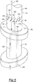
Figure 6 is a perspective view of another embodiment of the invention in which cooling fluid is directed into a gap between a sheath and a composite blade portion. - A plurality of different embodiments of the invention is shown in the Figures of the application. Similar features are shown in the various embodiments of the invention. Similar features have been numbered with a common reference numeral and have been differentiated by an alphabetic suffix. Also, to enhance consistency, the structures in any particular drawing share the same alphabetic suffix even if a particular feature is shown in less than all embodiments. Similar features are structured similarly, operate similarly, and/or have the same function unless otherwise indicated by the drawings or this specification. Furthermore, particular features of one embodiment can replace corresponding features in another embodiment or can supplement other embodiments unless otherwise indicated by the drawings or this specification.
- Rotor or propeller blades can be made of composite material with relatively low temperature capability. However, a pusher rotor configuration wich places the open rotor blades downstream from the core engine can have significant advantages over other engine configurations. Plumbing the exhaust through the rotor module can be problematic, leading to higher weight and cost. The higher diameter and weight rotor hubs can also lead to higher gyroscopic moments, necessitating larger, heavier shafting and bearings.
- The invention, as exemplified in several embodiments, would permit the pusher rotor configuration to dump the exhaust upstream of the blades, thereby enabling a lower weight and lower cost solution. The invention can also be applied to provide sacrificial protection for a composite blade. Damage from debris in the exhaust stream would be done to a replaceable protective sheath rather than the composite blade. An upstream dump of the exhaust would also enable a variable area nozzle since the core engine nozzle would now reside in a static environment rather than a rotating environment, making the task of creating a variable area nozzle much easier.
-
Figure 1 is a schematic representation of a turbine engine incorporating a first exemplary embodiment of the invention. Aturbine engine 10 can include aninlet 12 and be housed in anacelle 14. Theturbine engine 10 can also include acompressor section 16, acombustor section 18, and aturbine section 20. Theturbine engine 10 can also include anexhaust section 22. Thecompressor section 16,combustor section 18,turbine section 20, andexhaust section 22 can be arranged along acenterline axis 24. Components of thecompressor section 16 and theturbine section 20 can rotate about thecenterline axis 24. Fluid such as air can be drawn into theturbine engine 10 as indicated by the arrows referenced at 26. The fluid enters thecompressor section 16 from theinlet 12 and is compressed. Anose cone 28 can be proximate to theinlet 12 to gently direct air into thecompressor section 16. The schematically showncompressor section 16 includes high and low pressure compressor sections. In some embodiments, a portion of the fluid can be diverted radially outside of thecompressor section 16 and thereby become bypass flow. The compressed fluid emerging from thecompressor section 16 is mixed with fuel from afuel system 30 and ignited in thecombustor section 18. Combustion gases exit thecombustor section 18 and flow through theturbine section 20. Energy is extracted from the combustion gases in theturbine section 20. - A
turbine case 32 can encircle the core engine components (the compressor, combustor andturbine sections case 32 can support nonrotating structures such as compressor vanes (not shown) and turbine vanes. Exemplary turbine vanes are referenced at 34 and 36 and can be positioned to direct the flow of combustion gases to theturbine section 20. The combustion gases passing aft of theturbine section 20 are referenced by unnumbered arrows. - In the open rotor configuration shown in
Figure 1 , power can be drawn from the free power turbine components to rotaterotors hub portion blades blades turbines shaft 54. Combustion gases pass over and thereby cause rotation of thefree power turbines - The
shaft 54 can extend into agear box 56.Respective drive shafts 58, 60 can extend from thegear box 56. Thedrive shaft 58 is fixed for rotation with thehub portion 42 of therotor 38. The drive shaft 60 is fixed for rotation with thehub portion 44 of therotor 40. In operation, the gears (not shown) of thegear box 54 can transmit the power input by theshaft 54 into counter-rotation of therotors Figure 1 is a "pusher" open rotor configuration and it is noted that embodiments of the invention can be practiced with "tractor" open rotor configuration wherein the rotors are forward/upstream of the compressor section. -
Figure 1 also shows a first exemplary embodiment of the invention. Arotor blade assembly 62 includes thecomposite blade portion 46 extending alength 64 from a root 66 to atip 68. A leadingedge 72 of thecomposite blade portion 46 extends from thetip 68 to anend point 70 along thelength 64 between thetip 68 and the root 66. The leadingedge 72 can be defined by a relatively sharp edge or can be defined simply along the forward edge of thecomposite blade portion 46 that engages the air. - The
rotor blade assembly 62 also includes abase portion 74 fixed to thecomposite blade portion 46 proximate to the root 66. The base portion can be a hub attached to a plurality of blades, such as thehub portion 42 of the first exemplary embodiment of the invention. Alternatively, the base portion can be fixed to a single composite blade portion, such as thebase portion 74d shown inFigure 6 of another embodiment of the invention. Thebase portion 74 can be formed from a different material that thecomposite blade portion 46. For example, thebase portion 74 can be formed from metal. Thebase portion 74 and thecomposite blade portion 46 can be fixed together by bolts or any other suitable means in view of the operation of thecomposite blade portion 46. Also, a composite blade can be attached to a metal base or spar is by either laying it up right on the metal components or by adhesive. - The
rotor blade assembly 62 also includes asheath 76 extending around thecomposite blade portion 46. Thesheath 76 is positioned along thelength 64 adjacent to thebase portion 74 and between the root 66 and theend point 70 of the leadingedge 72. Thesheath 76 can be positioned such that combustion gases exiting theexhaust section 22 directly impinge on thesheath 76. Theexhaust section 22 can be configured such that exhaust gases are directed relatively precisely at thesheath 76, limiting the likelihood that exhaust gases will contact thecomposite blade portion 46. - As shown in
Figure 2 , theexemplary sheath 76 can includes first andsecond halves composite blade portion 46. It is noted that sheaths applied in various embodiments of the invention can include "halves" that are substantially mirror images of one another or halves that are not mirror images of one another. The first andsecond halves respective wall portions composite blade portion 46 and mesh at opposite ends 86, 88. The first andsecond halves respective flange portions aperture 94. Theflange portions seams seams exemplary sheath 76 can be fixed to the base portion 74 (shown inFigure 1 ) with bolts extending through the mounting apertures. Thecomposite blade portion 46 can include a flange portion sandwiched between theflange portions base portion 74. - As shown in
Figure 2 , thesheath 76 can be spaced outwardly from thecomposite blade portion 46 along at least part of thelength 64 that extends between the root 66 and theend point 70 of the leading edge 72 (all shown inFigure 1 ).Figure 2 shows a void orgap 100 between thewall portions composite blade portion 46. Thegap 100 can provide insulation for thecomposite blade portion 46, create a passage for cooling air, and/or tend to isolate the composite blade from debris damage from any debris in the exhaust stream. Thegap 100 can extend the entire portion of thelength 64 over which thesheath 76 and thecomposite blade portion 46 overlap or only a portion of thelength 64 over which thesheath 76 and thecomposite blade portion 46 overlap. Thegap 100 can extend about theentire perimeter 102 of thecomposite blade portion 46 or less than theentire perimeter 102. - The first and
second halves Figure 1 can be welded together if desired.Figure 3 shows another embodiment of the invention in which first andsecond halves second half 80a can be fixed to a base portion with fasteners extending through a mountingaperture 94a. Next, thefirst half 78a can be fixed to thesecond half 80a withcounter-sunk cap screws Figure 3 also shows agap 100a defined between thesheath 76a and thecomposite blade portion 46a. -
Figure 4 shows another embodiment of the invention is which first andsecond halves composite blade portion 46b. Awall portion 82b of thefirst half 78b can include acounter-sunk aperture 108b. Awall portion 84b of thesecond half 80b can include aboss 110b defining a threadedaperture 112b. Theboss 110b can pass through anaperture 114b defined in thecomposite blade portion 46b. A cap screw 104b can be received in theapertures second halves -
Figure 4 also shows an arrangement in which thesheath 76b contacts thecomposite blade portion 46b. Thesheath 76b is spaced outwardly from thecomposite blade portion 46b about a majority of theperimeter 102b. Stand-offs wall portions sheath 76b relative to thecomposite blade portion 46b. Thesheath 76b can be carried by thecomposite blade portion 46b via one or more bosses passing through thecomposite blade portion 46b or by some sort of flange with mounting apertures as shown inFigure 2 . -
Figure 5 shows another embodiment of the invention is which the sheath is mounted directly on a composite blade portion. Thesheath 76c includeswall portions composite blade portion 46c includes aroot 66c operable to connect to a base portion (not shown). Anaperture 114c extends through thecomposite blade portion 46c. Thewall portions apertures aperture 114c. Apin 126c can extend through theapertures sheath 76c relative to thecomposite blade portion 46c. - Embodiments of the invention include a cooling fluid delivery system operable to deliver fluid into the
gap 100.Figure 6 shows another embodiment of an invention in which acomposite blade portion 46d is fixed to abase portion 74d, such as with fasteners extending through mountingapertures 94d. Asheath 76d encircles a bottom of thecomposite blade portion 46d, radially inward from theleading edge 72d relative to an axis of rotation of thecomposite blade portion 46d (such as anaxis 24 shown inFigure 1 ). A cooling fluid delivery system can include aconduit 128d having anopening 130d defined by thecomposite blade portion 46d and positioned in thegap 100d between thesheath 76d and thecomposite blade portion 46d. The cooling fluid delivery system can be operable to bleed fluid from the compressor section 16 (shown inFigure 1 ) and route the fluid through theconduit 128d and into the gap 100b via theopening 130d. Instead of bleed air from the compressor, a separate air pump could supply air, perhaps an electrically driven air pump. Another option would be a passive system that would combine the ram pressure from a forward facing scoop with the centrifugal loading from the rotary motion within the rotor and the radially outward direction of the rotating passages to move air through the air gap. - The
conduit 128d can extend through thecomposite blade portion 46d along at least part of thelength 64d over which thecomposite blade portion 46d and thesheath 76d overlap. Alternatively, the a conduit can be spaced from thecomposite blade portion 46d along at least part of thelength 64d over which thecomposite blade portion 46d and thesheath 76d overlap. For example, aconduit 132d can include anopening 134d positioned in thegap 100d, spaced from thecomposite blade portion 46d. Routing the cooling fluid through thecomposite blade portion 46d, such as withconduit 128d, can be desirable to cool thecomposite blade portion 46d. Alternatively, routing the cooling fluid to circumvent thecomposite blade portion 46d, such as withconduit 132d, can be desirable to maintain thecomposite blade portion 46d as a solid structure. - The cooling fluid can escape or exhaust the
gap 100d through an aperture defined at least in part by thesheath 76d.Arrows 140d represent the flow of exhaust cooling fluid. Theexemplary sheath 76d can include a plurality of apertures, such asaperture 136d, formed in awall portion 78d of thesheath 76d and arranged about a perimeter of thecomposite blade portion 46d. In addition or alternatively, anaperture 138d can be formed in part by thesheath 76d and in part by thecomposite blade portion 46d. The flanged design shown could provide air passages to the air gap without holes in the base of the composite blade. A seal could be disposed underneath the flange that would circle the cooling passage outlet and the blade. For a flangeless design, holes would have to pass through the base of the airfoil into the air gap. - Another embodiment could be to have the axisymmetric base be metallic with an integral spar that would pass through the sheath and extend up into the base of the composite blade. This would eliminate all composite within the exhaust stream (even in the isolated area inside the sheath) and could make features such as holes through the spar for sheath attachment more feasible due to higher strength.
- While the invention has been described with reference to an exemplary embodiment, it will be understood by those skilled in the art that various changes may be made and equivalents may be substituted for elements thereof without departing from the scope of the invention. In addition, many modifications may be made to adapt a particular situation or material to the teachings of the invention without departing from the essential scope thereof. Therefore, it is intended that the invention not be limited to the particular embodiment disclosed as the best mode contemplated for carrying out this invention, but that the invention will include all embodiments falling within the scope of the appended claims.
Claims (14)
- A rotor blade assembly comprising:a composite blade portion (46, 46a, 46b, 46c, 46d) extending a length (64, 64d) from a root (66, 66c) to a tip (68), wherein a leading edge (72, 72d) of said composite blade portion (46, 46a, 46b, 46c, 46d) extends from said tip to an end point (70) along said length (64, 64d) between said tip and said root;a base portion (74, 74d) fixed to the root of said composite blade portion (46, 46a, 46b, 46c, 46d);a sheath (76, 76a, 76b, 76c, 76d) extending around said composite blade portion (46d), along said length (64d), and between said root (66, 66c) and said end point (70) of said leading edge (72, 72d), anda conduit (128d, 132d) for routing a cooling fluid, the conduit (128d, 132d) including an opening (130d, 134d) positioned in a gap (100d) between said sheath (76d) and said composite blade portion (46d) along at least a part of said length (64d) between said root and said end point of said leading edge (72d).
- The rotor blade assembly of claim 1 wherein said sheath (76d) is spaced outwardly from said composite blade portion (46d) along all of a portion of said length (64d) between said root and said end point of said leading edge (72d)
or wherein said sheath (76d) is spaced outwardly from said composite blade portion (46d) about the entire perimeter of said composite blade portion (46d)
or wherein said sheath (76d) is spaced outwardly from said composite blade portion (46d) about a majority of the entire perimeter of said composite blade portion (46d) along at least part of a portion of said length (64d) between said root and said end point of said leading edge (72d). - The rotor blade assembly of claim 1 wherein said sheath (76d) includes first and second halves respectively mountable on opposite sides of said composite blade portion (46d).
- The rotor blade assembly of claim 1 wherein said sheath (76d) is fixed to said base portion (74d)
or mounted on said composite blade portion (46d). - The rotor blade assembly of claim 1 wherein said conduit (128d) extends through said composite blade portion (46d) along at least part of said length between said root and said end point of said leading edge (72d)
or wherein said conduit (132d) is spaced from said composite blade portion (46d) along most of a portion of said length (64d) between said root and said end point of said leading edge (72d). - The rotor blade assembly of claim 1 further comprising at least one aperture (136d, 138d) defined at least in part by said sheath (76d), wherein said at least one aperture (136d, 138d) is operable to exhaust fluid directed into said gap (100d) by said conduit (128d, 132d).
- The rotor blade assembly of claim 6 wherein said at least one aperture is further defined as a plurality of apertures (136d) formed in said sheath (76d) and arranged about a perimeter of said composite blade portion (46d)
or wherein said at least one aperture (138d) is further defined as formed in part by said sheath (76d) and in part by said composite blade portion (46d). - A method comprising the steps of:providing a composite blade portion (46d) which extends a length (64d) from a root to a tip, wherein a leading edge (72d) of the composite blade portion (46d) extends from the tip to an end point along the length (64d) between the tip and the root;fixing a base portion (74d) to the root of the composite blade portion (46d);positioning a sheath (76d) such as to extend around the composite blade portion (46d) and positioning the sheath (76d) along the length (64d) and between the root and the end point of the leading edge (72d); andproviding a conduit (128d, 132d) for routing a cooling fluid, the conduit (128d, 132d) including an opening (130d, 134d) positioned in a gap (100d) between said sheath (76d) and said composite blade portion (46d) along at least a part of said length (64d) between said root and said end point of said leading edge (72d).
- The method of claim 8 further comprising the step of:
directing the cooling fluid between the sheath (76d) and the composite blade portion (46d). - The method of claim 8 wherein said directing step further comprises the step of:
routing the cooling fluid first through the composite blade portion (46d) along the length (64d) between the root and the end point of the leading edge (72d) and second into a gap (100d) between the sheath (76d) and the composite blade portion (46d). - The method of claim 8 further comprising the step of:
releasibly connecting the sheath (76d) to one of the base portion (74d) and the composite blade portion (46d). - An aircraft propulsion device (10) comprising:a compressor section (16);a combustor section (18) operable to receive compressed fluid from said compressor section (16);a turbine section (20) operable to receive combustion gases from said combustor section (18);an exhaust section (22) operable to receive combustion gases from said turbine section (20);a rotor blade assembly according to claim 1 positioned downstream of said exhaust section (22),wherein said base portion (74d) is formed from a different material than said composite blade portion (46d), andwherein said sheath (76d) is positioned such that combustion gases exiting said exhaust section (22) directly impinge on said sheath (76d).
- The aircraft propulsion device of claim 12 further comprising:
a cooling fluid delivery system operable to bleed fluid from said compressor section (16) and route the fluid to the conduit (128d, 132d). - The aircraft propulsion device of claim 12 wherein said sheath (76d) includes first and second halves respectively mountable around opposite sides of said composite blade portion (46d) and each of said first and second halves includes at least one stand-offs such that a radial gap (100d) is defined at least partially around said composite blade portion (46d) between said composite blade portion (46d) and said sheath (76d).
Applications Claiming Priority (2)
| Application Number | Priority Date | Filing Date | Title |
|---|---|---|---|
| US12/758,856 US8540481B2 (en) | 2010-04-13 | 2010-04-13 | Rotor blade assembly |
| PCT/US2011/032286 WO2011130386A1 (en) | 2010-04-13 | 2011-04-13 | Rotor blade assembly |
Publications (3)
| Publication Number | Publication Date |
|---|---|
| EP2558687A1 EP2558687A1 (en) | 2013-02-20 |
| EP2558687A4 EP2558687A4 (en) | 2017-10-25 |
| EP2558687B1 true EP2558687B1 (en) | 2020-04-01 |
Family
ID=44761051
Family Applications (1)
| Application Number | Title | Priority Date | Filing Date |
|---|---|---|---|
| EP11769512.2A Active EP2558687B1 (en) | 2010-04-13 | 2011-04-13 | Rotor blade assembly |
Country Status (4)
| Country | Link |
|---|---|
| US (1) | US8540481B2 (en) |
| EP (1) | EP2558687B1 (en) |
| CA (1) | CA2796456C (en) |
| WO (1) | WO2011130386A1 (en) |
Family Cites Families (23)
| Publication number | Priority date | Publication date | Assignee | Title |
|---|---|---|---|---|
| US2488783A (en) | 1945-03-12 | 1949-11-22 | Edward A Stalker | Gas turbine |
| US2623599A (en) * | 1947-11-26 | 1952-12-30 | United Aircraft Corp | Propeller blade stress distributing means |
| US2586054A (en) * | 1948-08-21 | 1952-02-19 | Northrop Aircraft Inc | Pusher turboprop exhaust system |
| US3734642A (en) * | 1971-06-29 | 1973-05-22 | United Aircraft Corp | Aerodynamic blade root end attachment |
| US4732538A (en) * | 1984-03-02 | 1988-03-22 | General Electric Company | Blade hub air scoop |
| US4789304A (en) * | 1987-09-03 | 1988-12-06 | United Technologies Corporation | Insulated propeller blade |
| US4930725A (en) * | 1988-12-16 | 1990-06-05 | Allied-Signal Inc. | Pusher propeller installation for turboprop engines |
| US4892269A (en) * | 1988-04-28 | 1990-01-09 | Allied-Signal Inc. | Spinner ducted exhaust for pusher turboprop engines |
| US4842663A (en) | 1988-04-29 | 1989-06-27 | Kramer Leslie D | Steam turbine blade anti-erosion shield and method of turbine blade repair |
| US5174024A (en) | 1990-09-17 | 1992-12-29 | Sterrett Terry L | Tail rotor abrasive strip |
| US5222297A (en) * | 1991-10-18 | 1993-06-29 | United Technologies Corporation | Composite blade manufacture |
| DE4208842C1 (en) | 1992-03-19 | 1993-04-08 | Eurocopter Hubschrauber Gmbh, 8000 Muenchen, De | |
| US5542820A (en) | 1994-12-23 | 1996-08-06 | United Technologies Corporation | Engineered ceramic components for the leading edge of a helicopter rotor blade |
| US5782607A (en) | 1996-12-11 | 1998-07-21 | United Technologies Corporation | Replaceable ceramic blade insert |
| US5908522A (en) | 1997-11-07 | 1999-06-01 | Composite Technology, Inc. | Supplemental leading edge wear strip for a rotor blade |
| GB0025012D0 (en) | 2000-10-12 | 2000-11-29 | Rolls Royce Plc | Cooling of gas turbine engine aerofoils |
| US6565312B1 (en) | 2001-12-19 | 2003-05-20 | The Boeing Company | Fluid-cooled turbine blades |
| US7758314B2 (en) | 2003-03-12 | 2010-07-20 | Florida Turbine Technologies, Inc. | Tungsten shell for a spar and shell turbine vane |
| US7186082B2 (en) | 2004-05-27 | 2007-03-06 | United Technologies Corporation | Cooled rotor blade and method for cooling a rotor blade |
| US7186092B2 (en) | 2004-07-26 | 2007-03-06 | General Electric Company | Airfoil having improved impact and erosion resistance and method for preparing same |
| US8210798B2 (en) * | 2008-02-13 | 2012-07-03 | United Technologies Corporation | Cooled pusher propeller system |
| US8182222B2 (en) | 2009-02-12 | 2012-05-22 | Hamilton Sundstrand Corporation | Thermal protection of rotor blades |
| US8727730B2 (en) * | 2010-04-06 | 2014-05-20 | General Electric Company | Composite turbine bucket assembly |
-
2010
- 2010-04-13 US US12/758,856 patent/US8540481B2/en not_active Expired - Fee Related
-
2011
- 2011-04-13 WO PCT/US2011/032286 patent/WO2011130386A1/en not_active Ceased
- 2011-04-13 CA CA2796456A patent/CA2796456C/en not_active Expired - Fee Related
- 2011-04-13 EP EP11769512.2A patent/EP2558687B1/en active Active
Non-Patent Citations (1)
| Title |
|---|
| None * |
Also Published As
| Publication number | Publication date |
|---|---|
| WO2011130386A1 (en) | 2011-10-20 |
| US8540481B2 (en) | 2013-09-24 |
| CA2796456A1 (en) | 2011-10-20 |
| EP2558687A1 (en) | 2013-02-20 |
| EP2558687A4 (en) | 2017-10-25 |
| US20110250075A1 (en) | 2011-10-13 |
| CA2796456C (en) | 2018-04-24 |
Similar Documents
| Publication | Publication Date | Title |
|---|---|---|
| US11306658B2 (en) | Cooling system for a turbine engine | |
| EP2333251A2 (en) | Fan containment case | |
| US6364603B1 (en) | Fan case for turbofan engine having a fan decoupler | |
| EP2562086B1 (en) | Nacelle assembly having integrated afterbody mount case | |
| EP1942253A2 (en) | Guide vane and method of fabricating the same | |
| US20080159856A1 (en) | Guide vane and method of fabricating the same | |
| US20080072569A1 (en) | Guide vane and method of fabricating the same | |
| EP2971660B1 (en) | Thermally conforming acoustic liner cartridge for a gas turbine engine | |
| EP3511528B1 (en) | Gas turbine engine component with integrally formed stiffeners | |
| CA2957457A1 (en) | Doubler attachment system | |
| US20230358148A1 (en) | Aircraft with ram air turbine disk with generator having blade shroud ring integrated magnets | |
| EP2233394B1 (en) | Propeller with thermally protected blades | |
| EP3018289B1 (en) | Fan blade with static dissipative coating | |
| EP1534935B1 (en) | Gas turbine comprising an energy absorber and deflection device | |
| US8403629B2 (en) | Stator for a jet engine, a jet engine comprising such a stator, and an aircraft comprising the jet engine | |
| US20230303264A1 (en) | Aircraft with ram air turbine disk with generator having blade tip integrated magnets | |
| CA2796456C (en) | Rotor assembly having a composite blade and sheath | |
| US12359587B2 (en) | Gas turbine engine power cable cooling | |
| US20190292989A1 (en) | Gas turbine engine heatshield | |
| EP4174288B1 (en) | Protection system for gas turbine engine in ice crystal conditions | |
| US20250290452A1 (en) | Turbine engine with accessory gearbox | |
| US12372030B2 (en) | Turbine engine having a fire box | |
| US20250075662A1 (en) | Turbine Engine having First and Second Accessory Gearboxes | |
| EP4685341A1 (en) | Diffuser-turbine flow network | |
| US20240287917A1 (en) | Aircraft turbine engine assembly comprising a support for equipment |
Legal Events
| Date | Code | Title | Description |
|---|---|---|---|
| PUAI | Public reference made under article 153(3) epc to a published international application that has entered the european phase |
Free format text: ORIGINAL CODE: 0009012 |
|
| 17P | Request for examination filed |
Effective date: 20121109 |
|
| AK | Designated contracting states |
Kind code of ref document: A1 Designated state(s): AL AT BE BG CH CY CZ DE DK EE ES FI FR GB GR HR HU IE IS IT LI LT LU LV MC MK MT NL NO PL PT RO RS SE SI SK SM TR |
|
| DAX | Request for extension of the european patent (deleted) | ||
| RA4 | Supplementary search report drawn up and despatched (corrected) |
Effective date: 20170921 |
|
| RIC1 | Information provided on ipc code assigned before grant |
Ipc: B64C 11/20 20060101ALI20170915BHEP Ipc: F01D 5/18 20060101AFI20170915BHEP Ipc: B64D 27/00 20060101ALI20170915BHEP |
|
| GRAP | Despatch of communication of intention to grant a patent |
Free format text: ORIGINAL CODE: EPIDOSNIGR1 |
|
| STAA | Information on the status of an ep patent application or granted ep patent |
Free format text: STATUS: GRANT OF PATENT IS INTENDED |
|
| RIC1 | Information provided on ipc code assigned before grant |
Ipc: F01D 5/18 20060101AFI20190906BHEP Ipc: B64C 11/20 20060101ALI20190906BHEP Ipc: B64D 27/00 20060101ALI20190906BHEP |
|
| INTG | Intention to grant announced |
Effective date: 20191016 |
|
| GRAS | Grant fee paid |
Free format text: ORIGINAL CODE: EPIDOSNIGR3 |
|
| GRAA | (expected) grant |
Free format text: ORIGINAL CODE: 0009210 |
|
| STAA | Information on the status of an ep patent application or granted ep patent |
Free format text: STATUS: THE PATENT HAS BEEN GRANTED |
|
| AK | Designated contracting states |
Kind code of ref document: B1 Designated state(s): AL AT BE BG CH CY CZ DE DK EE ES FI FR GB GR HR HU IE IS IT LI LT LU LV MC MK MT NL NO PL PT RO RS SE SI SK SM TR |
|
| REG | Reference to a national code |
Ref country code: GB Ref legal event code: FG4D |
|
| REG | Reference to a national code |
Ref country code: CH Ref legal event code: EP Ref country code: AT Ref legal event code: REF Ref document number: 1251567 Country of ref document: AT Kind code of ref document: T Effective date: 20200415 |
|
| REG | Reference to a national code |
Ref country code: DE Ref legal event code: R096 Ref document number: 602011066002 Country of ref document: DE |
|
| REG | Reference to a national code |
Ref country code: IE Ref legal event code: FG4D |
|
| PG25 | Lapsed in a contracting state [announced via postgrant information from national office to epo] |
Ref country code: BG Free format text: LAPSE BECAUSE OF FAILURE TO SUBMIT A TRANSLATION OF THE DESCRIPTION OR TO PAY THE FEE WITHIN THE PRESCRIBED TIME-LIMIT Effective date: 20200701 |
|
| REG | Reference to a national code |
Ref country code: NL Ref legal event code: MP Effective date: 20200401 |
|
| REG | Reference to a national code |
Ref country code: LT Ref legal event code: MG4D |
|
| PG25 | Lapsed in a contracting state [announced via postgrant information from national office to epo] |
Ref country code: NL Free format text: LAPSE BECAUSE OF FAILURE TO SUBMIT A TRANSLATION OF THE DESCRIPTION OR TO PAY THE FEE WITHIN THE PRESCRIBED TIME-LIMIT Effective date: 20200401 Ref country code: CZ Free format text: LAPSE BECAUSE OF FAILURE TO SUBMIT A TRANSLATION OF THE DESCRIPTION OR TO PAY THE FEE WITHIN THE PRESCRIBED TIME-LIMIT Effective date: 20200401 Ref country code: LT Free format text: LAPSE BECAUSE OF FAILURE TO SUBMIT A TRANSLATION OF THE DESCRIPTION OR TO PAY THE FEE WITHIN THE PRESCRIBED TIME-LIMIT Effective date: 20200401 Ref country code: PT Free format text: LAPSE BECAUSE OF FAILURE TO SUBMIT A TRANSLATION OF THE DESCRIPTION OR TO PAY THE FEE WITHIN THE PRESCRIBED TIME-LIMIT Effective date: 20200817 Ref country code: NO Free format text: LAPSE BECAUSE OF FAILURE TO SUBMIT A TRANSLATION OF THE DESCRIPTION OR TO PAY THE FEE WITHIN THE PRESCRIBED TIME-LIMIT Effective date: 20200701 Ref country code: GR Free format text: LAPSE BECAUSE OF FAILURE TO SUBMIT A TRANSLATION OF THE DESCRIPTION OR TO PAY THE FEE WITHIN THE PRESCRIBED TIME-LIMIT Effective date: 20200702 Ref country code: SE Free format text: LAPSE BECAUSE OF FAILURE TO SUBMIT A TRANSLATION OF THE DESCRIPTION OR TO PAY THE FEE WITHIN THE PRESCRIBED TIME-LIMIT Effective date: 20200401 Ref country code: IS Free format text: LAPSE BECAUSE OF FAILURE TO SUBMIT A TRANSLATION OF THE DESCRIPTION OR TO PAY THE FEE WITHIN THE PRESCRIBED TIME-LIMIT Effective date: 20200801 Ref country code: FI Free format text: LAPSE BECAUSE OF FAILURE TO SUBMIT A TRANSLATION OF THE DESCRIPTION OR TO PAY THE FEE WITHIN THE PRESCRIBED TIME-LIMIT Effective date: 20200401 |
|
| REG | Reference to a national code |
Ref country code: AT Ref legal event code: MK05 Ref document number: 1251567 Country of ref document: AT Kind code of ref document: T Effective date: 20200401 |
|
| PG25 | Lapsed in a contracting state [announced via postgrant information from national office to epo] |
Ref country code: HR Free format text: LAPSE BECAUSE OF FAILURE TO SUBMIT A TRANSLATION OF THE DESCRIPTION OR TO PAY THE FEE WITHIN THE PRESCRIBED TIME-LIMIT Effective date: 20200401 Ref country code: LV Free format text: LAPSE BECAUSE OF FAILURE TO SUBMIT A TRANSLATION OF THE DESCRIPTION OR TO PAY THE FEE WITHIN THE PRESCRIBED TIME-LIMIT Effective date: 20200401 Ref country code: RS Free format text: LAPSE BECAUSE OF FAILURE TO SUBMIT A TRANSLATION OF THE DESCRIPTION OR TO PAY THE FEE WITHIN THE PRESCRIBED TIME-LIMIT Effective date: 20200401 |
|
| REG | Reference to a national code |
Ref country code: CH Ref legal event code: PL |
|
| PG25 | Lapsed in a contracting state [announced via postgrant information from national office to epo] |
Ref country code: AL Free format text: LAPSE BECAUSE OF FAILURE TO SUBMIT A TRANSLATION OF THE DESCRIPTION OR TO PAY THE FEE WITHIN THE PRESCRIBED TIME-LIMIT Effective date: 20200401 |
|
| REG | Reference to a national code |
Ref country code: DE Ref legal event code: R097 Ref document number: 602011066002 Country of ref document: DE |
|
| PG25 | Lapsed in a contracting state [announced via postgrant information from national office to epo] |
Ref country code: SM Free format text: LAPSE BECAUSE OF FAILURE TO SUBMIT A TRANSLATION OF THE DESCRIPTION OR TO PAY THE FEE WITHIN THE PRESCRIBED TIME-LIMIT Effective date: 20200401 Ref country code: EE Free format text: LAPSE BECAUSE OF FAILURE TO SUBMIT A TRANSLATION OF THE DESCRIPTION OR TO PAY THE FEE WITHIN THE PRESCRIBED TIME-LIMIT Effective date: 20200401 Ref country code: RO Free format text: LAPSE BECAUSE OF FAILURE TO SUBMIT A TRANSLATION OF THE DESCRIPTION OR TO PAY THE FEE WITHIN THE PRESCRIBED TIME-LIMIT Effective date: 20200401 Ref country code: LI Free format text: LAPSE BECAUSE OF NON-PAYMENT OF DUE FEES Effective date: 20200430 Ref country code: CH Free format text: LAPSE BECAUSE OF NON-PAYMENT OF DUE FEES Effective date: 20200430 Ref country code: ES Free format text: LAPSE BECAUSE OF FAILURE TO SUBMIT A TRANSLATION OF THE DESCRIPTION OR TO PAY THE FEE WITHIN THE PRESCRIBED TIME-LIMIT Effective date: 20200401 Ref country code: LU Free format text: LAPSE BECAUSE OF NON-PAYMENT OF DUE FEES Effective date: 20200413 Ref country code: MC Free format text: LAPSE BECAUSE OF FAILURE TO SUBMIT A TRANSLATION OF THE DESCRIPTION OR TO PAY THE FEE WITHIN THE PRESCRIBED TIME-LIMIT Effective date: 20200401 Ref country code: DK Free format text: LAPSE BECAUSE OF FAILURE TO SUBMIT A TRANSLATION OF THE DESCRIPTION OR TO PAY THE FEE WITHIN THE PRESCRIBED TIME-LIMIT Effective date: 20200401 Ref country code: AT Free format text: LAPSE BECAUSE OF FAILURE TO SUBMIT A TRANSLATION OF THE DESCRIPTION OR TO PAY THE FEE WITHIN THE PRESCRIBED TIME-LIMIT Effective date: 20200401 Ref country code: IT Free format text: LAPSE BECAUSE OF FAILURE TO SUBMIT A TRANSLATION OF THE DESCRIPTION OR TO PAY THE FEE WITHIN THE PRESCRIBED TIME-LIMIT Effective date: 20200401 |
|
| REG | Reference to a national code |
Ref country code: BE Ref legal event code: MM Effective date: 20200430 |
|
| PLBE | No opposition filed within time limit |
Free format text: ORIGINAL CODE: 0009261 |
|
| STAA | Information on the status of an ep patent application or granted ep patent |
Free format text: STATUS: NO OPPOSITION FILED WITHIN TIME LIMIT |
|
| PG25 | Lapsed in a contracting state [announced via postgrant information from national office to epo] |
Ref country code: BE Free format text: LAPSE BECAUSE OF NON-PAYMENT OF DUE FEES Effective date: 20200430 Ref country code: SK Free format text: LAPSE BECAUSE OF FAILURE TO SUBMIT A TRANSLATION OF THE DESCRIPTION OR TO PAY THE FEE WITHIN THE PRESCRIBED TIME-LIMIT Effective date: 20200401 Ref country code: PL Free format text: LAPSE BECAUSE OF FAILURE TO SUBMIT A TRANSLATION OF THE DESCRIPTION OR TO PAY THE FEE WITHIN THE PRESCRIBED TIME-LIMIT Effective date: 20200401 |
|
| 26N | No opposition filed |
Effective date: 20210112 |
|
| GBPC | Gb: european patent ceased through non-payment of renewal fee |
Effective date: 20200701 |
|
| PG25 | Lapsed in a contracting state [announced via postgrant information from national office to epo] |
Ref country code: GB Free format text: LAPSE BECAUSE OF NON-PAYMENT OF DUE FEES Effective date: 20200701 Ref country code: IE Free format text: LAPSE BECAUSE OF NON-PAYMENT OF DUE FEES Effective date: 20200413 |
|
| PG25 | Lapsed in a contracting state [announced via postgrant information from national office to epo] |
Ref country code: SI Free format text: LAPSE BECAUSE OF FAILURE TO SUBMIT A TRANSLATION OF THE DESCRIPTION OR TO PAY THE FEE WITHIN THE PRESCRIBED TIME-LIMIT Effective date: 20200401 |
|
| PG25 | Lapsed in a contracting state [announced via postgrant information from national office to epo] |
Ref country code: TR Free format text: LAPSE BECAUSE OF FAILURE TO SUBMIT A TRANSLATION OF THE DESCRIPTION OR TO PAY THE FEE WITHIN THE PRESCRIBED TIME-LIMIT Effective date: 20200401 Ref country code: MT Free format text: LAPSE BECAUSE OF FAILURE TO SUBMIT A TRANSLATION OF THE DESCRIPTION OR TO PAY THE FEE WITHIN THE PRESCRIBED TIME-LIMIT Effective date: 20200401 Ref country code: CY Free format text: LAPSE BECAUSE OF FAILURE TO SUBMIT A TRANSLATION OF THE DESCRIPTION OR TO PAY THE FEE WITHIN THE PRESCRIBED TIME-LIMIT Effective date: 20200401 |
|
| PG25 | Lapsed in a contracting state [announced via postgrant information from national office to epo] |
Ref country code: MK Free format text: LAPSE BECAUSE OF FAILURE TO SUBMIT A TRANSLATION OF THE DESCRIPTION OR TO PAY THE FEE WITHIN THE PRESCRIBED TIME-LIMIT Effective date: 20200401 |
|
| P01 | Opt-out of the competence of the unified patent court (upc) registered |
Effective date: 20230528 |
|
| PGFP | Annual fee paid to national office [announced via postgrant information from national office to epo] |
Ref country code: FR Payment date: 20230421 Year of fee payment: 13 Ref country code: DE Payment date: 20230427 Year of fee payment: 13 |
|
| REG | Reference to a national code |
Ref country code: DE Ref legal event code: R119 Ref document number: 602011066002 Country of ref document: DE |
|
| PG25 | Lapsed in a contracting state [announced via postgrant information from national office to epo] |
Ref country code: DE Free format text: LAPSE BECAUSE OF NON-PAYMENT OF DUE FEES Effective date: 20241105 |
|
| PG25 | Lapsed in a contracting state [announced via postgrant information from national office to epo] |
Ref country code: FR Free format text: LAPSE BECAUSE OF NON-PAYMENT OF DUE FEES Effective date: 20240430 |
|
| PG25 | Lapsed in a contracting state [announced via postgrant information from national office to epo] |
Ref country code: FR Free format text: LAPSE BECAUSE OF NON-PAYMENT OF DUE FEES Effective date: 20240430 Ref country code: DE Free format text: LAPSE BECAUSE OF NON-PAYMENT OF DUE FEES Effective date: 20241105 |