EP2557750A1 - Channel estimation and peak to average power ratio reduction in multi-carrier modulation receivers - Google Patents
Channel estimation and peak to average power ratio reduction in multi-carrier modulation receivers Download PDFInfo
- Publication number
- EP2557750A1 EP2557750A1 EP12176261A EP12176261A EP2557750A1 EP 2557750 A1 EP2557750 A1 EP 2557750A1 EP 12176261 A EP12176261 A EP 12176261A EP 12176261 A EP12176261 A EP 12176261A EP 2557750 A1 EP2557750 A1 EP 2557750A1
- Authority
- EP
- European Patent Office
- Prior art keywords
- papr
- carrier types
- zero values
- carrier
- values
- Prior art date
- Legal status (The legal status is an assumption and is not a legal conclusion. Google has not performed a legal analysis and makes no representation as to the accuracy of the status listed.)
- Granted
Links
- 230000009467 reduction Effects 0.000 title description 16
- 238000000034 method Methods 0.000 claims abstract description 68
- 239000000969 carrier Substances 0.000 claims abstract description 32
- 230000003247 decreasing effect Effects 0.000 claims abstract description 5
- 230000005540 biological transmission Effects 0.000 description 17
- 230000008569 process Effects 0.000 description 10
- 238000004891 communication Methods 0.000 description 5
- 125000004122 cyclic group Chemical group 0.000 description 4
- 230000006870 function Effects 0.000 description 4
- 230000008859 change Effects 0.000 description 3
- 230000000694 effects Effects 0.000 description 3
- 238000012986 modification Methods 0.000 description 3
- 230000004048 modification Effects 0.000 description 3
- 230000003044 adaptive effect Effects 0.000 description 2
- 230000002411 adverse Effects 0.000 description 2
- 238000010586 diagram Methods 0.000 description 2
- 238000001914 filtration Methods 0.000 description 2
- 230000036039 immunity Effects 0.000 description 2
- 238000002347 injection Methods 0.000 description 2
- 239000007924 injection Substances 0.000 description 2
- 238000010295 mobile communication Methods 0.000 description 2
- 230000010363 phase shift Effects 0.000 description 2
- 238000001228 spectrum Methods 0.000 description 2
- 230000006978 adaptation Effects 0.000 description 1
- 230000003466 anti-cipated effect Effects 0.000 description 1
- 238000013459 approach Methods 0.000 description 1
- 230000033228 biological regulation Effects 0.000 description 1
- 238000010276 construction Methods 0.000 description 1
- 230000006735 deficit Effects 0.000 description 1
- 230000001419 dependent effect Effects 0.000 description 1
- 230000006872 improvement Effects 0.000 description 1
- 238000003780 insertion Methods 0.000 description 1
- 230000037431 insertion Effects 0.000 description 1
- 238000012804 iterative process Methods 0.000 description 1
- 230000004044 response Effects 0.000 description 1
- 238000005070 sampling Methods 0.000 description 1
- 230000011664 signaling Effects 0.000 description 1
- 239000000243 solution Substances 0.000 description 1
- 238000012549 training Methods 0.000 description 1
Images


Classifications
-
- H—ELECTRICITY
- H04—ELECTRIC COMMUNICATION TECHNIQUE
- H04L—TRANSMISSION OF DIGITAL INFORMATION, e.g. TELEGRAPHIC COMMUNICATION
- H04L25/00—Baseband systems
- H04L25/02—Details ; arrangements for supplying electrical power along data transmission lines
- H04L25/0202—Channel estimation
- H04L25/0224—Channel estimation using sounding signals
- H04L25/0226—Channel estimation using sounding signals sounding signals per se
-
- H—ELECTRICITY
- H04—ELECTRIC COMMUNICATION TECHNIQUE
- H04L—TRANSMISSION OF DIGITAL INFORMATION, e.g. TELEGRAPHIC COMMUNICATION
- H04L25/00—Baseband systems
- H04L25/02—Details ; arrangements for supplying electrical power along data transmission lines
-
- H—ELECTRICITY
- H04—ELECTRIC COMMUNICATION TECHNIQUE
- H04L—TRANSMISSION OF DIGITAL INFORMATION, e.g. TELEGRAPHIC COMMUNICATION
- H04L27/00—Modulated-carrier systems
- H04L27/26—Systems using multi-frequency codes
-
- H—ELECTRICITY
- H04—ELECTRIC COMMUNICATION TECHNIQUE
- H04L—TRANSMISSION OF DIGITAL INFORMATION, e.g. TELEGRAPHIC COMMUNICATION
- H04L27/00—Modulated-carrier systems
- H04L27/26—Systems using multi-frequency codes
- H04L27/2601—Multicarrier modulation systems
- H04L27/2614—Peak power aspects
- H04L27/2618—Reduction thereof using auxiliary subcarriers
-
- H—ELECTRICITY
- H04—ELECTRIC COMMUNICATION TECHNIQUE
- H04L—TRANSMISSION OF DIGITAL INFORMATION, e.g. TELEGRAPHIC COMMUNICATION
- H04L27/00—Modulated-carrier systems
- H04L27/26—Systems using multi-frequency codes
- H04L27/2601—Multicarrier modulation systems
- H04L27/2614—Peak power aspects
- H04L27/262—Reduction thereof by selection of pilot symbols
-
- H—ELECTRICITY
- H04—ELECTRIC COMMUNICATION TECHNIQUE
- H04L—TRANSMISSION OF DIGITAL INFORMATION, e.g. TELEGRAPHIC COMMUNICATION
- H04L25/00—Baseband systems
- H04L25/02—Details ; arrangements for supplying electrical power along data transmission lines
- H04L25/0202—Channel estimation
- H04L25/0224—Channel estimation using sounding signals
- H04L25/0228—Channel estimation using sounding signals with direct estimation from sounding signals
-
- H—ELECTRICITY
- H04—ELECTRIC COMMUNICATION TECHNIQUE
- H04L—TRANSMISSION OF DIGITAL INFORMATION, e.g. TELEGRAPHIC COMMUNICATION
- H04L27/00—Modulated-carrier systems
- H04L27/26—Systems using multi-frequency codes
- H04L27/2601—Multicarrier modulation systems
- H04L27/2626—Arrangements specific to the transmitter only
-
- H—ELECTRICITY
- H04—ELECTRIC COMMUNICATION TECHNIQUE
- H04L—TRANSMISSION OF DIGITAL INFORMATION, e.g. TELEGRAPHIC COMMUNICATION
- H04L27/00—Modulated-carrier systems
- H04L27/26—Systems using multi-frequency codes
- H04L27/2601—Multicarrier modulation systems
- H04L27/2647—Arrangements specific to the receiver only
-
- H—ELECTRICITY
- H04—ELECTRIC COMMUNICATION TECHNIQUE
- H04L—TRANSMISSION OF DIGITAL INFORMATION, e.g. TELEGRAPHIC COMMUNICATION
- H04L5/00—Arrangements affording multiple use of the transmission path
- H04L5/0001—Arrangements for dividing the transmission path
- H04L5/0003—Two-dimensional division
- H04L5/0005—Time-frequency
- H04L5/0007—Time-frequency the frequencies being orthogonal, e.g. OFDM(A), DMT
-
- H—ELECTRICITY
- H04—ELECTRIC COMMUNICATION TECHNIQUE
- H04L—TRANSMISSION OF DIGITAL INFORMATION, e.g. TELEGRAPHIC COMMUNICATION
- H04L5/00—Arrangements affording multiple use of the transmission path
- H04L5/003—Arrangements for allocating sub-channels of the transmission path
- H04L5/0048—Allocation of pilot signals, i.e. of signals known to the receiver
Definitions
- the present invention generally relates to digital video broadcasting (DVB). More specifically, the present invention relates to reducing Peak to Average Power Ratio (PAPR) in multi-carrier modulation based DVB systems.
- PAPR Peak to Average Power Ratio
- DVB is the European consortium standard for the broadcast transmission of digital terrestrial television.
- DVB systems transmit a compressed digital audio/video stream, using multi-carrier modulation, such as orthogonal frequency division multiplexing (OFDM).
- OFDM orthogonal frequency division multiplexing
- Another popular method of transmitting signals is digital video broadcasting-terrestrial (DVB-T).
- DVD-T digital video broadcasting-terrestrial
- broadcasters employ this method, the transmitted signals do not travel via cable. Instead, they move from aerial antenna to aerial antenna, and from a signal blaster to home receiver.
- DVB-T broadcasters transmit data using a compressed digital audio-video stream, with the entire process based on a Moving Picture Expert Group (MPEG) - 2 standard.
- MPEG Moving Picture Expert Group
- These transmissions can include all kinds of digital broadcasting, including high definition television (HDTV) and other high-intensity methods. This is an improvement over the old analog signals, which required separate streams of transmission.
- Impulse noise is a growing concern in DVB-T transmissions because of its negative impact upon transmitted digital data and is common in OFDM based systems.
- OFDM based DVB-T system receivers provide a level of inherent immunity against impulse noise, this immunity is insufficient to ensure that digital TV signals are reliably transmitted in accordance with applicable standards.
- OFDM systems include data that is transmitted on multiple carriers simultaneously. In real life, when data is transmitted, it is passed through a data channel. This data channel subsequently manifests itself as a multiplicative impairment (e.g., impulse noise) on one of more of these carriers when they are received on a receiver side.
- multiplicative impairment e.g., impulse noise
- Some of the traditional techniques for reducing PAPR in OFDM systems include, by way of example, tone reservation, tone injection, or adaptive constellation extension. Each of these techniques is well understood by those of skill in the relevant art and will not be discussed in depth herein. All of these techniques, however, cause either a loss in data rate or an increase in the signal-to-noise ratio (SNR) required for reception. These techniques, therefore, have only limited utility.
- SNR signal-to-noise ratio
- pilot signals with known data patterns are transmitted.
- the pilot signals sometimes called pilot tones or simply pilots, are used to support channel estimation operations.
- Traditional channel estimation operations attempt to estimate the amplitude and phase distortion introduced by the communications channel and can thus compensate for the SNR losses discussed above. Although more effective than many of the other techniques, channel estimation operations are not precise enough to completely compensate for all SNR losses.
- the present invention includes a method for performing channel estimation in an Orthogonal Frequency Division Multiplexed (OFDM) signal.
- the method includes performing the channel estimation based upon use of reserved tone channel carriers.
- Embodiments of the present invention provide reductions in PAPR comparable to the traditional techniques above. In the embodiments of the present invention, however, SNR losses are compensated for by improving the precision of the channel estimation process.
- OFDM systems work by splitting a wide-band digital signal into a large number of slower digital streams and then transmitting them all of the streams on a set of closely spaced adjacent carrier frequencies (i.e., tones).
- Each of the streams includes different types of tones.
- a typical stream e.g., symbol
- some of these tones can be reserved for PAPR reduction.
- the present invention parameterizes an allowable set of values for the reserved tones.
- Typical parameterizations include values from a linear feedback shift register, or a finite number of known quantized values.
- the transmitter finds the best signal from the parameterized set of values for PAPR reduction, during an initialization process, and then signals the chosen parameters (possibly in a robust channel).
- the receiver then decodes the parameters and uses the reserved tones as additional pilots to improve channel estimation.
- PAPR reduction is typically lost because the search space for data values for the reserved tones is reduced.
- additional known techniques such as the Adaptive Constellation Extension (ACE) can be applied to gain further reductions.
- ACE Adaptive Constellation Extension
- the process of computing the final reserved tone values can be arrived at via an iterative technique that includes multiple PAPR reduction techniques.
- FIG. 1 is a block diagram illustration of a conventional OFDM based DVB-T system
- FIG. 2 is a graphical illustration of an exemplary pilot pattern sequence according to known channel estimation techniques
- FIG. 3 is a graphical illustration of a single symbol sequence before choosing reserved tone values according to known channel estimation techniques
- FIG. 4 is a graphical illustration of a single symbol sequence before choosing reserved tone values according to known channel estimation techniques
- FIG. 5 is a graphical illustration of a single symbol sequence after choosing reserved tone values from known pattern subsets in accordance with an embodiment of the present invention.
- FIG. 6 is an exemplary flowchart of a method of practicing an embodiment of the present invention.
- FIG. 1 is a block diagram showing constructions of transmission/reception terminals of a conventional OFDM mobile communication system.
- a mobile communication system using OFDM scheme includes a transmission terminal 100 and a reception terminal 150.
- the transmission terminal 100 includes a data transmitter 102, a coder 104, a symbol mapper 106, a serial to parallel (S/P) converter 108, a pilot symbol inserter 110, an inverse fast Fourier transform (IFFT) unit 112, a parallel to serial (P/S) converter 114, a guard interval inserter 116, a digital-to-analog (D/A) converter 118, and a radio frequency (RF) processor 120.
- IFFT inverse fast Fourier transform
- the data transmitter 102 In the transmission terminal 100, the data transmitter 102 generates and outputs user data bits and control data bits to be transmitted to the coder 104.
- the coder 104 receives and codes the signals outputted from the data transmitter 102 according to a predetermined coding scheme, and then outputs the coded signals to the symbol mapper 106.
- the coder 104 may perform coding by means of a convolutional coding scheme or a turbo coding scheme having a predetermined coding rate.
- the symbol mapper 106 modulates the coded bits outputted from the coder 104 according to a corresponding modulation scheme, thereby generating modulation symbols, and outputs the modulation symbols to the S/P converter 108.
- the modulation scheme that the symbol mapper 106 may follow includes, e.g., a binary phase shift keying (BPSK) scheme, a quadrature phase shift keying (QPSK) scheme, a 16 quadrature amplitude modulation (QAM) scheme, 64QAM scheme, or others.
- BPSK binary phase shift keying
- QPSK quadrature phase shift keying
- QAM 16 quadrature amplitude modulation
- 64QAM scheme 64QAM scheme, or others.
- the S/P converter 108 receives and converts the serial modulation symbols outputted from the symbol mapper 106 into parallel modulation symbols, and outputs the converted parallel modulation symbols to the pilot symbol inserter 110.
- the pilot symbol inserter 110 inserts pilot symbols into the converted parallel modulation symbols outputted from the S/P converter 108 and then outputs them to the IFFT unit 112.
- the IFFT unit 112 receives the signals outputted from the pilot symbol inserted 110, performs N-point IFFT for the signals, and then outputs them to the P/S converter 114.
- the P/S converter 114 receives the signals outputted from the IFFT unit 112, converts the signals into serial signals, and outputs the converted serial signals to the guard interval inserter 116.
- the guard interval inserter 116 receives the signals outputted from the P/S converter 114, inserts guard intervals into the received signals, and then outputs them to the D/A converter 118.
- the inserted guard interval prevents interference between OFDM symbols transmitted in the OFDM communication system; that is to say, the inserted guard interval prevents interference between a previous OFDM symbol transmitted during a previous OFDM symbol period and a current OFDM symbol to be transmitted during a current OFDM symbol period.
- a method of inserting null data has been proposed.
- insertion of null data as a guard interval may cause a receiver to erroneously estimate a start point of an OFDM symbol, thereby allowing interference between sub-carriers, which increases the probability of erroneous determination of the starting point for received OFDM symbols. Therefore, a cyclic prefix method or a cyclic postfix method is usually used in inserting the guard interval.
- a cyclic prefix method a predetermined number of last bits of an OFDM symbol are copied and inserted into an OFDM symbol.
- cyclic postfix method a predetermined number of initial bits of an OFDM symbol are copied and inserted into an OFDM symbol.
- the D/A converter 118 receives the signals outputted from the guard interval inserter 116, converts the signals into analog signals, and outputs the converted analog signals to the RF processor 120.
- the RF processor 120 includes a filter and a front end unit. The RF processor 120 receives the signals from the D/A converter 118, RF-processes the signals, and then transmits the signals over the air through a Tx antenna.
- the reception terminal 150 will be described.
- the reception terminal 150 includes an RF processor 152, an analog-to-digital (A/D) converter 154, a guard interval remover 156, a S/P converter 158, a fast Fourier transform (FFT) unit 160, a pilot symbol extractor 162, a channel estimator 164, an equalizer 166, a P/S converter 168, a symbol demapper 170, a decoder 172, and a data receiver 174.
- A/D analog-to-digital
- FFT fast Fourier transform
- the signals transmitted from the transmission terminal 100 pass through multi-path channels and are received by an Rx antenna of the reception terminal 150 in a state in which noise is included in the signals.
- the signals received through the Rx antenna are inputted to the RF processor 152, and the RF processor 152 down-converts the received signals into signals of an intermediate frequency (IF) band, and then outputs the IF signals to the A/D converter 154.
- the A/D converter 154 converts the analog signals outputted from the RF processor 152 into digital signals and then outputs the digital signals to the guard interval remover 156.
- the guard interval remover 156 receives the digital signals converted by and outputted from the A/D converter 154, eliminates guard intervals from the digital signals, and then outputs them to the S/P converter 158.
- the S/P converter 158 receives the serial signals outputted from the guard interval remover 156, converts the serial signals into parallel signals, and then outputs the parallel signals to the FFT unit 160.
- the FFT unit 160 performs N-point FFT on the signals outputted from the P/S converter 158, and then outputs them to both the equalizer 166 and the pilot symbol extractor 162.
- the equalizer 166 receives the signals from the FFT unit 160, channel-equalizes the signals, and then outputs the channel-equalized signals to the P/S converter 168.
- the P/S converter 168 receives the parallel signals outputted from the equalizer 166, converts the parallel signals into serial signals, and then outputs the converted serial signals to the symbol demapper 170.
- the signals outputted from the FFT unit 160 are also inputted to the pilot symbol extractor 162.
- the pilot symbol extractor 162 detects pilot symbols from the signals outputted from the FFT unit 160 and outputs the detected pilot symbols to the channel estimator 164.
- the channel estimator 164 performs channel estimation using the pilot symbols and outputs the result of the channel estimation to the equalizer 166.
- the reception terminal 150 generates channel quality information (hereinafter, referred to as "CQI") corresponding to the result of the channel estimation and transmits the CQI to the transmission terminal 100 through a CQI transmitter (not shown).
- CQI channel quality information
- the symbol demapper 170 receives the signals outputted from the P/S converter 168, demodulates the signals according to a demodulation scheme corresponding to the modulation scheme of the transmission terminal 100, and then outputs the demodulated signals to the decoder 172.
- the decoder 172 decodes the signals from the symbol demapper 170 according to a decoding scheme corresponding to the coding scheme of the transmission terminal 100 and outputs the decoded signals to the data receiver 174.
- OFDM systems data is transmitted and received via multiple carrier frequencies.
- OFDM systems there can be approximately 128 independent OFDM sub-carriers (i.e., tones) that occupy approximately 528 megahertz of bandwidth.
- data is modulated and transmitted via many of these sub-carriers.
- Approximately 10 of the sub-carriers do not necessarily carry information.
- pilot tones also referred to as pilot tones, may be used to guard the information carrying sub- carriers, to simplify the filtering requirements of the system, or to provide reference phase/amplitude information for the demodulator.
- the positions of the pilot tones may be defined according to the communication standard or defined by the user/designer of the system. Some pilot tones are located on two ends of the frequency spectrum and some of the pilot tones are interspersed within the frequency spectrum.
- an OFDM receiver For each transmitted carrier signal, an OFDM receiver normally attempts to compensate for the distortion induced by the transmission channel. This will normally involve a channel estimation operation and a channel compensation operation.
- pilot signals with known data patterns are transmitted.
- the pilot signals sometimes called pilot tones or simply pilots, are used to support channel estimation operations. Such channel estimation operations normally attempt to estimate the amplitude and phase distortion introduced by the communications channel.
- the pattern structure of the pilots can be in essentially any manner, provided that the Nyquist sampling criteria for the communication channel's impulse response and rate of change are satisfied.
- the number of pilots transmitted is often a function of the expected multipath distortion delay and the anticipated rate of change in channel conditions. However, for purposes of efficiency, it is desirable to minimize the number of pilots transmitted since the transmission of a pilot precludes the transmission of data in the transmission slot used to transmit the pilot.
- DVB-T OFDM systems often use their pilot tones for the purpose of making channel estimation easier.
- the sparseness of these tones renders it difficult to estimate the channel quickly and with efficient memory usage and calculations.
- Channel estimation is an important and necessary function for modem wireless receivers. With even a limited knowledge of the wireless channel properties, a receiver can gain insight into the information that was sent by the transmitter.
- the goal of channel estimation is to measure the effects of the channel on known, or partially known transmissions. A channel will change with changing conditions and topology. OFDM systems are especially suited for channel estimation.
- the subcarriers are closely spaced and the system is generally used in high speed applications that are capable of computing channel estimates with minimal delay.
- Subcarriers that are sent with a known power and make-up are called pilots and are used for synchronization and.
- the present invention provides a unique and novel approach to accomplishing channel estimation.
- the present invention provides enhancements to known channel estimation techniques, such as tone reservation.
- tone reservation for example, carriers are reserved and populated with arbitrary values in order to decrease the PAPR.
- the present invention is illustrated in the following example.
- non-arbitrary values can be chosen for carriers that are known. That is, for example, in a given symbol, carriers 3, 7, and 10 are available and instead of using arbitrary values for each of these carriers can take five values (e.g., -2, -1, 0, 1, and 2).
- there are 125 choices i.e., 5 3 ).
- each of the 125 choices includes sufficient granularity such that the PAPR could be decreased by an amount comparable to PAPR reduction using the arbitrary values, noted above. In this scenario, the PAPR could be reduced almost as much as it could by using the arbitrary values.
- the receiver has more information with which to perform channel estimates and equalization.
- the ability to provide this information to the receiver enables these carries to be used as pilots.
- pilots Traditionally, only dedicated pilots could be used to provide channel estimates.
- the present invention enables additional, non-pilot channel carriers, to be used to provide the channel estimates.
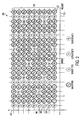
- FIG. 2 is a graphical illustration of a pilot pattern sequence 200 formulated in accordance with known channel estimation techniques.
- the pilot pattern sequence 200 includes a symbol group 202 of nine OFDM symbols arranged along a Y axis 204.
- the Y axis 204 for example, can be in gradations of 200 microseconds ( ⁇ s) up to 1 millisecond. The fidelity of these gradations is dependent upon the total duration of each of the OFDM symbols.
- the graph of FTG. 2 also includes an X axis 206.
- Each of the symbols within the symbol group 202 includes different carrier types comprising data carries (d ij ), continuous pilots (c ij ), scattered pilots (s ij ), and reserved tones (r ij ).
- the reserved tones (r ij ) are generally unused.
- the pilot sequence 200 is representative of a sequence configured for use in a DVB-T2 system, it can apply to any OFDM system.
- the first element in the carrier type subscript (e.g. d ij ) represents a carrier index.
- the second element of the subscript represents a time index.
- a first OFDM symbol 207, occurring at time 0 includes a continuous pilot c 0,0 , a data carrier d 1 , 0 , a data carrier d 2 , 0 , etc.
- the data carriers are representative of actual transmitted data.
- the continuous pilots and the scattered pilots are provided to be able to perform channel estimation.
- the continuous pilots are c 0,0 and c 0,15 .
- the symbol 207 also includes a scattered pilot s 12,0 . The notion of why two different types of pilots are used is well understood by those of skill in the art and will not be discussed herein.
- OFDM systems include the concept of having pilots that are not located within any particular system.
- all of the continuous pilots have a carrier index identical to other carrier pilots, meaning they are in vertical columns with other continuous pilots.
- the fact that the continuous pilots are all in vertical columns together means that the pilot location stays the same, across different symbols. That is, if carrier 0 is a pilot in symbol 0 (i.e., symbol 207), then carrier 0 is also a pilot in a symbol 208, carrier 0 is also a pilot in symbol 210, etc. This process is typical of DVB-T systems and wireless local area network (LAN) systems.
- LAN wireless local area network
- pilot configurations such as the configuration of FIG. 2
- the density of the continuous pilots is typically insufficient to adequately perform channel estimation.
- roving or "scattered" pilots are provided to augment the channel estimation capability of the continuous pilots.
- s 12,0 the scattered pilot is denoted as s 12,0 .
- the symbol 208 includes a scattered pilot s 9,1 etc. These are the typical types of pilots that can be found in conventional OFDM systems.
- FIG. 3 is a graphical illustration 300 of a single symbol sequence, prior to choosing reserved tone values, according to known channel estimation techniques. More specifically, FIG. 3 is an illustration of the single symbol 207 shown in FIG. 2 , and is representative of a single symbol occurring at time index "0." In FIG. 3 , the "0s" have been removed from the time index column for purposes of simplification.
- reserved tones such as the reserved tones (r ij )
- the data carries (d ij ), the continuous pilots (c ij ), and the scattered pilots (s ij ) are assigned specific values first.
- a fast Fourier transform (FFT) 302 is applied to the values assigned to the data carriers, the continuous pilots, and the scattered pilots to create a time domain signal 304.
- This newly computed time domain signal 304 might potentially have a high PAPR.
- the continuous pilots (c ij ), and the scattered pilots (s ij ) could be used to perform the channel estimation to decode (and record) the data embedded within the data carriers (d ij ).
- values for the reserved tones (r 5 ) and (r 19 ) are chosen as zero.
- FIG. 4 is a graphical illustration 400 of the single symbol 207 before choosing reserved tone values according to known channel estimation techniques.
- arbitrary values for the reserved tones (r ij ) are selected.
- arbitrary non-zero complex values for the reserved tones (r 5 ) and (r 19 ) can be selected.
- Methods for reserve tone determination and selection are provided, for example in a Thesis by J. Tellado, Peak to average power reduction for multicarrier modulation, Ph.D. dissertation, Stanford, CA: Stanford Univ., 2000.
- the values for (r 5 ) and (r 19 ) are zero.
- these reserve tone values although arbitrary, are chosen to be non-zero values. More specifically, the non-zero values are chosen such that when an FFT 402 is applied thereto, a minimum PAPR can be achieved since the continuous pilots (c ij ), the scattered pilots (s ij ) and the data carriers (d ij ) are fixed.
- the reserve tone values (r 5 ) and (r 19 ) are chosen to be part of a pilot pattern from some limited set, which is from a subset of reserved carrier pilots.
- the reserve tone values are not the same as the arbitrary values from FIG. 4 .
- the reserve tone values (r 5 ) and (r 19 ) are chosen to be close enough to the reserve tone values from FIG. 4 such that the resulting signal has a low PAPR.
- the reserve tones (r 5 ) and (r 19 ) can be used as pilots to assist and improve the channel estimation process. This process is illustrated more clearly in FIGs. 5 and 6 below.
- reserve tone values can be determined. All of these values can be determined ahead of time. They can also, however, be determined dynamically during an iterative process that commences during receiver initialization. Generally, all these methods use a projection of signal peaks onto the reserved tones to produce a reduction signal. This reduction signal is then used for peak-canceling purposes in order to lower the PAPR of the OFDM transmitter.
- the first k reserved tones are allowed to be any of the elements from a known large set such as ⁇ a+ib, a is a multiple of 0.08 and so is b ⁇ .
- the later reserved tones are produced by filtering the previous tones with a known filter.
- the receiver would estimate the first k reserved tones using traditional methods and the rest would follow from them. Allowing for 64 different filters (requiring only 6 bits of signaling), allowing a and b to be between -2 and +2, and allowing k to be a small number (e.g., 15), numerous possible tone patterns can provide substantial PAPR reductions.
- a second method for choosing reserve tone values is essentially the same as the first method above.
- a and b are generated using linear feedback shift registers (LFSRs). Numerous other well known techniques for choosing reserve tone values are available.
- FIG. 5 is a graphical illustration 500 of the single symbol sequence 207 after choosing reserved tone values from known pattern subsets, in accordance with an embodiment of the present invention.
- the reserved tones (r 5 ) and (r 19 ) which have similar characteristics to continuous pilots (c 0 , and c 15 ) and scattered pilot s 12 , are used to assist in enhanced channel estimation.
- scattered pilots could be used instead of reserved tones.
- reserved tone values for (r 5 ) and (r 19 ) can be determined using one of the methods noted above. More specifically, reserved tone values for (r 5 ) and (r 19 ), shown as (r' 5 ) and (r' 19 ) respectively, are chosen to be non-zero and non-arbitrary.
- An FFT 502 is applied to the values (r' 5 ) and (r' 19 ) to produce a low, but not necessarily a minimum, PAPR 504.
- the present invention includes embodiments that transmit known values to an OFDM receiver using reserved tones to provide more precise channel estimation.
- Middle values chosen for the reserved tones, can be added or subtracted in accordance with the technique illustrated in FIG. 5 , for all of the carriers.
- Middle values are those values that can be constrained (i.e., adding or subtracting other values) in different ways that will not adversely affect the PAPR reduction. These values can be constrained in some way, as represented by constraint sets A5 and A19 shown in FIG. 5 , and are derived from a finite set. In this manner, the OFDM receiver has additional information that can be used to provide more accurate channel estimates, or decode or de-map the actual transmitted value more accurately. This process can also be used for tone injection.
- middle values allows various techniques to be used to decrease the PAPR while simultaneously permitting reserve tone carriers, for example r' 5 and r' 19 , shown in FIG. 5 , to be used as pilot tones. If arbitrary complex values are used for the reserve tone carriers, higher PAPR reduction values can be achieved. However, it is possible to use sub-optimal, albeit acceptable, values for PAPR reduction, where there may be two or three possible constraint set solutions. For example, if three pilot carriers are used, middle values could be chosen such as 1, -1, and 2. Many other combinations of middle values can be chosen.
- sequences can be used that will not adversely affect the PAPR reduction capabilities, but would fit within the constraint sets A5 and A19 (i.e., the set of values actually permitted), associated with r' 5 and r' 19 , respectively.
- FIG. 6 is an exemplary flowchart 600 of a method of practicing an embodiment of the present invention. More specifically, he method 600 includes a method for decreasing PAPR for a multicarrier modulation signal including two or more groups of carriers.
- a step 602 during a first timeframe non-zero values are assigned for carrier types within a first of the two or more groups. Additionally, zero values are assigned for carrier types within a second of the two or more groups after assigning the non-zero values.
- arbitrary non-zero values are chosen for the carrier types within the second group.
- non-zero values for the carrier types within the second group are chosen based upon a predetermined PAPR threshold.
- the method 600 can be implemented, for example, during a transmitter training phase or an initialization process.
Abstract
Description
- The present invention generally relates to digital video broadcasting (DVB). More specifically, the present invention relates to reducing Peak to Average Power Ratio (PAPR) in multi-carrier modulation based DVB systems.
- As known to those of skill in the art, DVB is the European consortium standard for the broadcast transmission of digital terrestrial television. DVB systems transmit a compressed digital audio/video stream, using multi-carrier modulation, such as orthogonal frequency division multiplexing (OFDM). Another popular method of transmitting signals is digital video broadcasting-terrestrial (DVB-T). When broadcasters employ this method, the transmitted signals do not travel via cable. Instead, they move from aerial antenna to aerial antenna, and from a signal blaster to home receiver.
- DVB-T broadcasters transmit data using a compressed digital audio-video stream, with the entire process based on a Moving Picture Expert Group (MPEG) - 2 standard. These transmissions can include all kinds of digital broadcasting, including high definition television (HDTV) and other high-intensity methods. This is an improvement over the old analog signals, which required separate streams of transmission.
- Impulse noise is a growing concern in DVB-T transmissions because of its negative impact upon transmitted digital data and is common in OFDM based systems. Although OFDM based DVB-T system receivers provide a level of inherent immunity against impulse noise, this immunity is insufficient to ensure that digital TV signals are reliably transmitted in accordance with applicable standards. As an example, OFDM systems include data that is transmitted on multiple carriers simultaneously. In real life, when data is transmitted, it is passed through a data channel. This data channel subsequently manifests itself as a multiplicative impairment (e.g., impulse noise) on one of more of these carriers when they are received on a receiver side.
- While impulse noise has traditionally been ignored in North American TV receiver market, several standards/specifications in the European market require high tolerance to impulse noise. Another troublesome aspect of OFDM systems is PAPR, which impacts the presence and effects of impulse noise. By reducing PAPR, the effects of impulse noise can correspondingly be reduced.
- Some of the traditional techniques for reducing PAPR in OFDM systems include, by way of example, tone reservation, tone injection, or adaptive constellation extension. Each of these techniques is well understood by those of skill in the relevant art and will not be discussed in depth herein. All of these techniques, however, cause either a loss in data rate or an increase in the signal-to-noise ratio (SNR) required for reception. These techniques, therefore, have only limited utility.
- To assist a receiver in overcoming multi-path distortion, pilot signals with known data patterns are transmitted. The pilot signals, sometimes called pilot tones or simply pilots, are used to support channel estimation operations. Traditional channel estimation operations attempt to estimate the amplitude and phase distortion introduced by the communications channel and can thus compensate for the SNR losses discussed above. Although more effective than many of the other techniques, channel estimation operations are not precise enough to completely compensate for all SNR losses.
- What is needed, therefore, are improved methods and systems for reducing PAPR in OFDM based DVB-T system receivers that can compensate for corresponding losses in SNR.
- Consistent with the principles of the present invention as embodied and broadly described herein, the present invention includes a method for performing channel estimation in an Orthogonal Frequency Division Multiplexed (OFDM) signal. The method includes performing the channel estimation based upon use of reserved tone channel carriers.
- Embodiments of the present invention provide reductions in PAPR comparable to the traditional techniques above. In the embodiments of the present invention, however, SNR losses are compensated for by improving the precision of the channel estimation process.
- By way of example, OFDM systems work by splitting a wide-band digital signal into a large number of slower digital streams and then transmitting them all of the streams on a set of closely spaced adjacent carrier frequencies (i.e., tones). Each of the streams includes different types of tones. For example, a typical stream (e.g., symbol) might include data carries, reserved tones, continuous pilots, and scattered pilots. As understood by those of skill in the art, some of these tones can be reserved for PAPR reduction. Once the data carriers are filled with data, appropriate values of the extra data (i.e., channel estimation data) are inserted into the reserved carriers to decrease the PAPR of the time domain signal.
- The present invention parameterizes an allowable set of values for the reserved tones. Typical parameterizations include values from a linear feedback shift register, or a finite number of known quantized values. The transmitter finds the best signal from the parameterized set of values for PAPR reduction, during an initialization process, and then signals the chosen parameters (possibly in a robust channel). The receiver then decodes the parameters and uses the reserved tones as additional pilots to improve channel estimation.
- Some PAPR reduction is typically lost because the search space for data values for the reserved tones is reduced. However, given the more accurate channel estimation operations of the present invention, additional known techniques such as the Adaptive Constellation Extension (ACE) can be applied to gain further reductions. The process of computing the final reserved tone values can be arrived at via an iterative technique that includes multiple PAPR reduction techniques.
- Further embodiments, features, and advantages of the present invention, as well as the structure and operation of the various embodiments of the present invention, are described in detail below with reference to the accompanying drawings.
- The accompanying drawings, which are incorporated herein and form part of the specification, illustrate the present invention and, together with the description, further serve to explain the principles of the invention and to enable a person skilled in the relevant art(s) to make and use the invention.
-
FIG. 1 is a block diagram illustration of a conventional OFDM based DVB-T system; -
FIG. 2 is a graphical illustration of an exemplary pilot pattern sequence according to known channel estimation techniques; -
FIG. 3 is a graphical illustration of a single symbol sequence before choosing reserved tone values according to known channel estimation techniques; -
FIG. 4 is a graphical illustration of a single symbol sequence before choosing reserved tone values according to known channel estimation techniques; -
FIG. 5 is a graphical illustration of a single symbol sequence after choosing reserved tone values from known pattern subsets in accordance with an embodiment of the present invention; and -
FIG. 6 is an exemplary flowchart of a method of practicing an embodiment of the present invention. - The following detailed description of the present invention refers to the accompanying drawings that illustrate exemplary embodiments consistent with this invention. Other embodiments are possible, and modifications may be made to the embodiments within the spirit and scope of the invention. Therefore, the detailed description is not meant to limit the invention. Rather, the scope of the invention is defined by the appended claims.
- It would be apparent to one of skill in the art that the present invention, as described below, may be implemented in many different embodiments of software, hardware, firmware, and/or the entities illustrated in the figures. Any actual software code with the specialized control of hardware to implement the present invention is not limiting of the present invention. Thus, the operational behavior of the present invention will be described with the understanding that modifications and variations of the embodiments are possible, given the level of detail presented herein.
-
FIG. 1 is a block diagram showing constructions of transmission/reception terminals of a conventional OFDM mobile communication system. Referring toFIG. 1 , a mobile communication system using OFDM scheme includes atransmission terminal 100 and areception terminal 150. Thetransmission terminal 100 includes adata transmitter 102, acoder 104, asymbol mapper 106, a serial to parallel (S/P)converter 108, apilot symbol inserter 110, an inverse fast Fourier transform (IFFT)unit 112, a parallel to serial (P/S)converter 114, aguard interval inserter 116, a digital-to-analog (D/A)converter 118, and a radio frequency (RF)processor 120. - In the
transmission terminal 100, thedata transmitter 102 generates and outputs user data bits and control data bits to be transmitted to thecoder 104. Thecoder 104 receives and codes the signals outputted from thedata transmitter 102 according to a predetermined coding scheme, and then outputs the coded signals to thesymbol mapper 106. Thecoder 104 may perform coding by means of a convolutional coding scheme or a turbo coding scheme having a predetermined coding rate. Thesymbol mapper 106 modulates the coded bits outputted from thecoder 104 according to a corresponding modulation scheme, thereby generating modulation symbols, and outputs the modulation symbols to the S/P converter 108. Here, the modulation scheme that thesymbol mapper 106 may follow includes, e.g., a binary phase shift keying (BPSK) scheme, a quadrature phase shift keying (QPSK) scheme, a 16 quadrature amplitude modulation (QAM) scheme, 64QAM scheme, or others. - The S/
P converter 108 receives and converts the serial modulation symbols outputted from thesymbol mapper 106 into parallel modulation symbols, and outputs the converted parallel modulation symbols to thepilot symbol inserter 110. Thepilot symbol inserter 110 inserts pilot symbols into the converted parallel modulation symbols outputted from the S/P converter 108 and then outputs them to theIFFT unit 112. - The
IFFT unit 112 receives the signals outputted from the pilot symbol inserted 110, performs N-point IFFT for the signals, and then outputs them to the P/S converter 114. The P/S converter 114 receives the signals outputted from theIFFT unit 112, converts the signals into serial signals, and outputs the converted serial signals to theguard interval inserter 116. Theguard interval inserter 116 receives the signals outputted from the P/S converter 114, inserts guard intervals into the received signals, and then outputs them to the D/A converter 118. Here, the inserted guard interval prevents interference between OFDM symbols transmitted in the OFDM communication system; that is to say, the inserted guard interval prevents interference between a previous OFDM symbol transmitted during a previous OFDM symbol period and a current OFDM symbol to be transmitted during a current OFDM symbol period. - In inserting the guard interval, a method of inserting null data has been proposed. However, insertion of null data as a guard interval may cause a receiver to erroneously estimate a start point of an OFDM symbol, thereby allowing interference between sub-carriers, which increases the probability of erroneous determination of the starting point for received OFDM symbols. Therefore, a cyclic prefix method or a cyclic postfix method is usually used in inserting the guard interval. In the cyclic prefix method, a predetermined number of last bits of an OFDM symbol are copied and inserted into an OFDM symbol. In the cyclic postfix method, a predetermined number of initial bits of an OFDM symbol are copied and inserted into an OFDM symbol.
- The D/
A converter 118 receives the signals outputted from theguard interval inserter 116, converts the signals into analog signals, and outputs the converted analog signals to theRF processor 120. TheRF processor 120 includes a filter and a front end unit. TheRF processor 120 receives the signals from the D/A converter 118, RF-processes the signals, and then transmits the signals over the air through a Tx antenna. Hereinafter, thereception terminal 150 will be described. - The
reception terminal 150 includes anRF processor 152, an analog-to-digital (A/D)converter 154, aguard interval remover 156, a S/P converter 158, a fast Fourier transform (FFT)unit 160, apilot symbol extractor 162, achannel estimator 164, anequalizer 166, a P/S converter 168, asymbol demapper 170, adecoder 172, and adata receiver 174. - The signals transmitted from the
transmission terminal 100 pass through multi-path channels and are received by an Rx antenna of thereception terminal 150 in a state in which noise is included in the signals. The signals received through the Rx antenna are inputted to theRF processor 152, and theRF processor 152 down-converts the received signals into signals of an intermediate frequency (IF) band, and then outputs the IF signals to the A/D converter 154. The A/D converter 154 converts the analog signals outputted from theRF processor 152 into digital signals and then outputs the digital signals to theguard interval remover 156. - The
guard interval remover 156 receives the digital signals converted by and outputted from the A/D converter 154, eliminates guard intervals from the digital signals, and then outputs them to the S/P converter 158. The S/P converter 158 receives the serial signals outputted from theguard interval remover 156, converts the serial signals into parallel signals, and then outputs the parallel signals to theFFT unit 160. TheFFT unit 160 performs N-point FFT on the signals outputted from the P/S converter 158, and then outputs them to both theequalizer 166 and thepilot symbol extractor 162. Theequalizer 166 receives the signals from theFFT unit 160, channel-equalizes the signals, and then outputs the channel-equalized signals to the P/S converter 168. The P/S converter 168 receives the parallel signals outputted from theequalizer 166, converts the parallel signals into serial signals, and then outputs the converted serial signals to thesymbol demapper 170. - As indicated, the signals outputted from the
FFT unit 160 are also inputted to thepilot symbol extractor 162. Thepilot symbol extractor 162 detects pilot symbols from the signals outputted from theFFT unit 160 and outputs the detected pilot symbols to thechannel estimator 164. Thechannel estimator 164 performs channel estimation using the pilot symbols and outputs the result of the channel estimation to theequalizer 166. Here, thereception terminal 150 generates channel quality information (hereinafter, referred to as "CQI") corresponding to the result of the channel estimation and transmits the CQI to thetransmission terminal 100 through a CQI transmitter (not shown). - The symbol demapper 170 receives the signals outputted from the P/
S converter 168, demodulates the signals according to a demodulation scheme corresponding to the modulation scheme of thetransmission terminal 100, and then outputs the demodulated signals to thedecoder 172. Thedecoder 172 decodes the signals from thesymbol demapper 170 according to a decoding scheme corresponding to the coding scheme of thetransmission terminal 100 and outputs the decoded signals to thedata receiver 174. - In OFDM systems, data is transmitted and received via multiple carrier frequencies. In some OFDM systems, for example, there can be approximately 128 independent OFDM sub-carriers (i.e., tones) that occupy approximately 528 megahertz of bandwidth. In these systems, data is modulated and transmitted via many of these sub-carriers. Approximately 10 of the sub-carriers do not necessarily carry information. These sub-carriers, also referred to as pilot tones, may be used to guard the information carrying sub- carriers, to simplify the filtering requirements of the system, or to provide reference phase/amplitude information for the demodulator. The positions of the pilot tones may be defined according to the communication standard or defined by the user/designer of the system. Some pilot tones are located on two ends of the frequency spectrum and some of the pilot tones are interspersed within the frequency spectrum.
- For each transmitted carrier signal, an OFDM receiver normally attempts to compensate for the distortion induced by the transmission channel. This will normally involve a channel estimation operation and a channel compensation operation. To assist a receiver in overcoming multipath distortion, pilot signals with known data patterns are transmitted. The pilot signals, sometimes called pilot tones or simply pilots, are used to support channel estimation operations. Such channel estimation operations normally attempt to estimate the amplitude and phase distortion introduced by the communications channel.
- The pattern structure of the pilots can be in essentially any manner, provided that the Nyquist sampling criteria for the communication channel's impulse response and rate of change are satisfied. The number of pilots transmitted is often a function of the expected multipath distortion delay and the anticipated rate of change in channel conditions. However, for purposes of efficiency, it is desirable to minimize the number of pilots transmitted since the transmission of a pilot precludes the transmission of data in the transmission slot used to transmit the pilot.
- DVB-T OFDM systems often use their pilot tones for the purpose of making channel estimation easier. However, the sparseness of these tones renders it difficult to estimate the channel quickly and with efficient memory usage and calculations.
- Channel estimation is an important and necessary function for modem wireless receivers. With even a limited knowledge of the wireless channel properties, a receiver can gain insight into the information that was sent by the transmitter. The goal of channel estimation is to measure the effects of the channel on known, or partially known transmissions. A channel will change with changing conditions and topology. OFDM systems are especially suited for channel estimation. The subcarriers are closely spaced and the system is generally used in high speed applications that are capable of computing channel estimates with minimal delay. Subcarriers that are sent with a known power and make-up are called pilots and are used for synchronization and. As noted above, the present invention provides a unique and novel approach to accomplishing channel estimation.
- More specifically, the present invention provides enhancements to known channel estimation techniques, such as tone reservation. In tone reservation, for example, carriers are reserved and populated with arbitrary values in order to decrease the PAPR.
- The present invention, on the other hand, is illustrated in the following example. Assume that non-arbitrary values can be chosen for carriers that are known. That is, for example, in a given symbol, carriers 3, 7, and 10 are available and instead of using arbitrary values for each of these carriers can take five values (e.g., -2, -1, 0, 1, and 2). Thus, there are 125 choices (i.e., 53). Assume that each of the 125 choices includes sufficient granularity such that the PAPR could be decreased by an amount comparable to PAPR reduction using the arbitrary values, noted above. In this scenario, the PAPR could be reduced almost as much as it could by using the arbitrary values. By using small sets of non-arbitrary values, however, the receiver has more information with which to perform channel estimates and equalization. The ability to provide this information to the receiver enables these carries to be used as pilots. Traditionally, only dedicated pilots could be used to provide channel estimates. The present invention enables additional, non-pilot channel carriers, to be used to provide the channel estimates.
-
FIG. 2 is a graphical illustration of a pilot pattern sequence 200 formulated in accordance with known channel estimation techniques. The pilot pattern sequence 200 includes a symbol group 202 of nine OFDM symbols arranged along a Y axis 204. The Y axis 204, for example, can be in gradations of 200 microseconds (µs) up to 1 millisecond. The fidelity of these gradations is dependent upon the total duration of each of the OFDM symbols. The graph of FTG. 2 also includes anX axis 206. - Each of the symbols within the symbol group 202 includes different carrier types comprising data carries (d ij ), continuous pilots (c ij ), scattered pilots (s ij ), and reserved tones (r ij ). The reserved tones (r ij ) are generally unused. Although the pilot sequence 200 is representative of a sequence configured for use in a DVB-T2 system, it can apply to any OFDM system.
- The first element in the carrier type subscript (e.g. d ij ) represents a carrier index. The second element of the subscript represents a time index. For example, in
FIG. 2 , afirst OFDM symbol 207, occurring attime 0 includes a continuous pilot c0,0, a data carrier d 1,0 , a data carrier d 2,0 , etc. - In an OFDM symbol, the data carriers are representative of actual transmitted data. The continuous pilots and the scattered pilots are provided to be able to perform channel estimation. For the
symbol 207, the continuous pilots are c0,0 and c0,15. Thesymbol 207 also includes a scattered pilot s12,0. The notion of why two different types of pilots are used is well understood by those of skill in the art and will not be discussed herein. - Focusing on other aspects of pilots signals, most OFDM systems include the concept of having pilots that are not located within any particular system. For example, in the symbol group 202, all of the continuous pilots have a carrier index identical to other carrier pilots, meaning they are in vertical columns with other continuous pilots. For example, there are continuous pilots at carrier index "0" and carrier index "15." The fact that the continuous pilots are all in vertical columns together means that the pilot location stays the same, across different symbols. That is, if
carrier 0 is a pilot in symbol 0 (i.e., symbol 207), thencarrier 0 is also a pilot in a symbol 208,carrier 0 is also a pilot in symbol 210, etc. This process is typical of DVB-T systems and wireless local area network (LAN) systems. - The problem, however, with pilot configurations such as the configuration of
FIG. 2 is that the density of the continuous pilots is typically insufficient to adequately perform channel estimation. To compensate for this lack of continuous pilot density, roving or "scattered" pilots are provided to augment the channel estimation capability of the continuous pilots. InFIG. 2 , as discussed above, in thesymbol 207 the scattered pilot is denoted as s12,0. The symbol 208 includes a scattered pilot s9,1 etc. These are the typical types of pilots that can be found in conventional OFDM systems. -
FIG. 3 is agraphical illustration 300 of a single symbol sequence, prior to choosing reserved tone values, according to known channel estimation techniques. More specifically,FIG. 3 is an illustration of thesingle symbol 207 shown inFIG. 2 , and is representative of a single symbol occurring at time index "0." InFIG. 3 , the "0s" have been removed from the time index column for purposes of simplification. - By way of background, before reserved tones, such as the reserved tones (r ij ), are assigned proper non-zero values, the data carries (d ij ), the continuous pilots (c ij ), and the scattered pilots (s ij ) are assigned specific values first. After this assignment, a fast Fourier transform (FFT) 302 is applied to the values assigned to the data carriers, the continuous pilots, and the scattered pilots to create a
time domain signal 304. This newly computedtime domain signal 304, for example, might potentially have a high PAPR. If thetime domain signal 304 has a high PAPR and if there are no reserve tones, the continuous pilots (c ij ), and the scattered pilots (s ij ) could be used to perform the channel estimation to decode (and record) the data embedded within the data carriers (d ij ). InFIG. 3 , values for the reserved tones (r 5 ) and (r 19 ) are chosen as zero. -
FIG. 4 is agraphical illustration 400 of thesingle symbol 207 before choosing reserved tone values according to known channel estimation techniques. InFIG. 4 , arbitrary values for the reserved tones (r ij ) are selected. By way of example, using methods well understood by those of skill in the art, arbitrary non-zero complex values for the reserved tones (r 5 ) and (r 19 ) can be selected. Methods for reserve tone determination and selection are provided, for example in a Thesis by J. Tellado, Peak to average power reduction for multicarrier modulation, Ph.D. dissertation, Stanford, CA: Stanford Univ., 2000. InFIG. 3 , the values for (r 5 ) and (r 19 ) are zero. - In
FIG. 4 , these reserve tone values, although arbitrary, are chosen to be non-zero values. More specifically, the non-zero values are chosen such that when anFFT 402 is applied thereto, a minimum PAPR can be achieved since the continuous pilots (c ij ), the scattered pilots (s ij ) and the data carriers (d ij ) are fixed. - Before application of reserved tones, all carriers must have some value. Since the maximum transmit power is limited by regulation, if no carrier is used, its value is set to 0 so that the useful carriers may be transmitted at higher power. For the purposes of the present invention, however, these values can be selected randomly. This random selection would cause, with very high probability, the equivalent time domain signal to have high PAPR.
- In embodiments of the present invention, instead of choosing the reserve tone values (r 5 ) and (r 19 ) as arbitrary values, they are chosen to be part of a pilot pattern from some limited set, which is from a subset of reserved carrier pilots. In the present invention, the reserve tone values are not the same as the arbitrary values from
FIG. 4 . Instead, the reserve tone values (r 5 ) and (r 19 ) are chosen to be close enough to the reserve tone values fromFIG. 4 such that the resulting signal has a low PAPR. As a result of this value selection process, the reserve tones (r 5 ) and (r 19 ) can be used as pilots to assist and improve the channel estimation process. This process is illustrated more clearly inFIGs. 5 and6 below. - In accordance with known methods, such as those highlighted in the thesis noted above, reserve tone values can be determined. All of these values can be determined ahead of time. They can also, however, be determined dynamically during an iterative process that commences during receiver initialization. Generally, all these methods use a projection of signal peaks onto the reserved tones to produce a reduction signal. This reduction signal is then used for peak-canceling purposes in order to lower the PAPR of the OFDM transmitter.
- In a first method, the first k reserved tones are allowed to be any of the elements from a known large set such as {a+ib, a is a multiple of 0.08 and so is b}. The later reserved tones are produced by filtering the previous tones with a known filter. In this scenario, the receiver would estimate the first k reserved tones using traditional methods and the rest would follow from them. Allowing for 64 different filters (requiring only 6 bits of signaling), allowing a and b to be between -2 and +2, and allowing k to be a small number (e.g., 15), numerous possible tone patterns can provide substantial PAPR reductions.
- A second method for choosing reserve tone values is essentially the same as the first method above. In the second method, however, a and b are generated using linear feedback shift registers (LFSRs). Numerous other well known techniques for choosing reserve tone values are available.
-
FIG. 5 is agraphical illustration 500 of thesingle symbol sequence 207 after choosing reserved tone values from known pattern subsets, in accordance with an embodiment of the present invention. InFIG. 5 , for example, in order to decrease the PAPR, the reserved tones (r 5 ) and (r 19 ), which have similar characteristics to continuous pilots (c 0 , and c15 ) and scattered pilot s12, are used to assist in enhanced channel estimation. Although specifically dedicated reserve tones are used in the example ofFIG. 5 , scattered pilots could be used instead of reserved tones. - In
FIG. 5 , the value of reserved tones (r 5 ) and (r 19 ) can be determined using one of the methods noted above. More specifically, reserved tone values for (r 5 ) and (r 19 ), shown as (r' 5 ) and (r' 19 ) respectively, are chosen to be non-zero and non-arbitrary. AnFFT 502 is applied to the values (r' 5 ) and (r' 19 ) to produce a low, but not necessarily a minimum,PAPR 504. - The present invention includes embodiments that transmit known values to an OFDM receiver using reserved tones to provide more precise channel estimation. Middle values, chosen for the reserved tones, can be added or subtracted in accordance with the technique illustrated in
FIG. 5 , for all of the carriers. Middle values are those values that can be constrained (i.e., adding or subtracting other values) in different ways that will not adversely affect the PAPR reduction. These values can be constrained in some way, as represented by constraint sets A5 and A19 shown inFIG. 5 , and are derived from a finite set. In this manner, the OFDM receiver has additional information that can be used to provide more accurate channel estimates, or decode or de-map the actual transmitted value more accurately. This process can also be used for tone injection. - In the embodiments discussed above, the use of middle values allows various techniques to be used to decrease the PAPR while simultaneously permitting reserve tone carriers, for example r'5 and r'19, shown in
FIG. 5 , to be used as pilot tones. If arbitrary complex values are used for the reserve tone carriers, higher PAPR reduction values can be achieved. However, it is possible to use sub-optimal, albeit acceptable, values for PAPR reduction, where there may be two or three possible constraint set solutions. For example, if three pilot carriers are used, middle values could be chosen such as 1, -1, and 2. Many other combinations of middle values can be chosen. So with these middle values, sequences can be used that will not adversely affect the PAPR reduction capabilities, but would fit within the constraint sets A5 and A19 (i.e., the set of values actually permitted), associated with r'5 and r'19, respectively. -
FIG. 6 is anexemplary flowchart 600 of a method of practicing an embodiment of the present invention. More specifically, hemethod 600 includes a method for decreasing PAPR for a multicarrier modulation signal including two or more groups of carriers. In astep 602 during a first timeframe, non-zero values are assigned for carrier types within a first of the two or more groups. Additionally, zero values are assigned for carrier types within a second of the two or more groups after assigning the non-zero values. During a second timeframe instep 604, arbitrary non-zero values are chosen for the carrier types within the second group. Within astep 606 during a third timeframe, non-zero values for the carrier types within the second group are chosen based upon a predetermined PAPR threshold. Themethod 600 can be implemented, for example, during a transmitter training phase or an initialization process. - It is to be appreciated that the Detailed Description section, and not the Summary and Abstract sections, is intended to be used to interpret the claims. The Summary and Abstract sections may set forth one or more but not all exemplary embodiments of the present invention as contemplated by the inventor(s), and thus, are not intended to limit the present invention and the appended claims in any way.
- The present invention has been described above with the aid of functional building blocks illustrating the implementation of specified functions and relationships thereof. The boundaries of these functional building blocks have been arbitrarily defined herein for the convenience of the description. Alternate boundaries can be defined so long as the specified functions and relationships thereof are appropriately performed.
- The foregoing description of the specific embodiments will so fully reveal the general nature of the invention that others can, by applying knowledge within the skill of the art, readily modify and/or adapt for various applications such specific embodiments, without undue experimentation, without departing from the general concept of the present invention. Therefore, such adaptations and modifications are intended to be within the meaning and range of equivalents of the disclosed embodiments, based on the teaching and guidance presented herein. It is to be understood that the phraseology or terminology herein is for the purpose of description and not of limitation, such that the terminology or phraseology of the present specification is to be interpreted by the skilled artisan in light of the teachings and guidance.
- The breadth and scope of the present invention should not be limited by any of the above-described exemplary embodiments, but should be defined only in accordance with the following claims and their equivalents.
- The claims in the instant application are different than those of the parent application or other related applications. The Applicant therefore rescinds any disclaimer of claim scope made in the parent application or any predecessor application in relation to the instant application. The Examiner is therefore advised that any such previous disclaimer and the cited references that it was made to avoid, may need to be revisited. Further, the Examiner is also reminded that any disclaimer made in the instant application should not be read into or against the parent application.
Claims (16)
- A method for decreasing peak to average power ratio, PAPR, for a multicarrier modulation signal including two or more groups of carriers, the method comprising:(a) during a first timeframe (i) assigning non-zero values for carrier types within a first of the two or more groups and (ii) assigning zero values for carrier types within a second of the two or more groups after assigning the non-zero values;(b) during a second timeframe (i) choosing arbitrary non-zero values for the carrier types within the second group; and(c) during a third timeframe optimally determining non-zero values for the carrier types within the second group based upon a predetermined PAPR threshold.
- The method of claim 1, wherein step (a) includes selecting a target PAPR, choosing a set of reserved tones, and
wherein step (a) further comprises (iii) computing a first PAPR and determining whether the first PAPR meets predetermined constraints. - The method of claim 2, wherein the step (a)(iii) includes computing a fast Fourier transform.
- The method of claim 3, wherein step (b) further comprises (ii) computing a second PAPR based upon the arbitrary non-zero value carrier types within the second group if the first PAPR does not meet the predetermined constraints and (iii) determining whether the computed PAPR meets predetermined constraints.
- The method of claim 1, wherein carrier types within the first group include at least one of data carriers, continuous pilots, and scattered pilots; and
wherein carrier types within the second group include reserved tones. - The method of claim 1, wherein steps (a)-(c) are performed during an initialization sequence.
- The method of claim 6, wherein the multi-carrier modulation signal is at least one of an orthogonal frequency division multiplexing, OFDM, signal and a discrete multi-tone modulation, DMT, signal.
- The method of claim 7, wherein steps (a)-(c) are performed within an OFDM transmitter.
- A computer readable medium carrying one or more sequences of one or more instructions for execution by one or more processors to perform a method of decreasing peak to average power ratio, PAPR, for a multi-carrier modulation signal including two or more groups of carriers, such that the instructions, when executed by the one or more processors, cause the one or more processors to:(a) during a first timeframe (i) assign non-zero values for carrier types within a first of the two or more groups and (ii) assign zero values for carrier types within a second of the two or more groups after assigning the non-zero values;(b) during a second timeframe (i) choose arbitrary non-zero values for the carrier types within the second group; and(c) during a third timeframe optimally determine non-zero values for the carrier types within the second group based upon a predetermined PAPR threshold.
- The computer readable medium of claim 9, wherein step (a) includes selecting a target PAPR, choosing a set of reserved tones, and
wherein step (a) further comprises (iii) computing a first PAPR and determining whether the first PAPR meets predetermined constraints. - The computer readable medium of claim 10, wherein the step (a)(iii) includes computing a fast Fourier transform.
- The computer readable medium of claim 11, wherein step (b) further comprises (ii) computing a second PAPR based upon the arbitrary non-zero value carrier types within the second group if the first PAPR does not meet the predetermined constraints and (iii) determining whether the computed PAPR meets predetermined constraints.
- The computer readable medium of claim 9, wherein carrier types within the first group include at least one of data carriers, continuous pilots, and scattered pilots; and wherein carrier types within the second group includes reserved tones.
- The computer readable medium of claim 9, wherein steps (a)-(c) are performed during an initialization sequence.
- The computer readable medium of claim 14, wherein the multi-carrier modulation signal is at least one of an orthogonal frequency division multiplexing, OFDM, signal and a discrete multi-tone modulation, DMT, signal.
- The computer readable medium of claim 15, wherein steps (a)-(c) are performed within an OFDM transmitter.
Applications Claiming Priority (4)
| Application Number | Priority Date | Filing Date | Title |
|---|---|---|---|
| US11653308P | 2008-11-20 | 2008-11-20 | |
| US11655308P | 2008-11-20 | 2008-11-20 | |
| US12/415,747 US8306148B2 (en) | 2008-11-20 | 2009-03-31 | Method to reduce peak to average power ratio in multi-carrier modulation receivers |
| EP09756614A EP2359559A2 (en) | 2008-11-20 | 2009-11-13 | Channel estimation and peak to average power ratio reduction in multi-carrier modulation receivers |
Related Parent Applications (2)
| Application Number | Title | Priority Date | Filing Date |
|---|---|---|---|
| EP09756614A Division EP2359559A2 (en) | 2008-11-20 | 2009-11-13 | Channel estimation and peak to average power ratio reduction in multi-carrier modulation receivers |
| EP09756614.5 Division | 2009-11-13 |
Publications (2)
| Publication Number | Publication Date |
|---|---|
| EP2557750A1 true EP2557750A1 (en) | 2013-02-13 |
| EP2557750B1 EP2557750B1 (en) | 2016-11-02 |
Family
ID=42172074
Family Applications (2)
| Application Number | Title | Priority Date | Filing Date |
|---|---|---|---|
| EP09756614A Withdrawn EP2359559A2 (en) | 2008-11-20 | 2009-11-13 | Channel estimation and peak to average power ratio reduction in multi-carrier modulation receivers |
| EP12176261.1A Active EP2557750B1 (en) | 2008-11-20 | 2009-11-13 | Channel estimation and peak to average power ratio reduction in multi-carrier modulation receivers |
Family Applications Before (1)
| Application Number | Title | Priority Date | Filing Date |
|---|---|---|---|
| EP09756614A Withdrawn EP2359559A2 (en) | 2008-11-20 | 2009-11-13 | Channel estimation and peak to average power ratio reduction in multi-carrier modulation receivers |
Country Status (6)
| Country | Link |
|---|---|
| US (3) | US8306148B2 (en) |
| EP (2) | EP2359559A2 (en) |
| JP (2) | JP5984392B2 (en) |
| KR (1) | KR101628887B1 (en) |
| CN (2) | CN103634243B (en) |
| WO (1) | WO2010059521A2 (en) |
Families Citing this family (24)
| Publication number | Priority date | Publication date | Assignee | Title |
|---|---|---|---|---|
| US8422434B2 (en) | 2003-02-18 | 2013-04-16 | Qualcomm Incorporated | Peak-to-average power ratio management for multi-carrier modulation in wireless communication systems |
| JP4968331B2 (en) * | 2007-04-13 | 2012-07-04 | 富士通株式会社 | Peak suppression method |
| KR20120099838A (en) * | 2011-03-02 | 2012-09-12 | 삼성전자주식회사 | Apparatus and method for reducing papr of broadcasting communication system |
| US8903001B2 (en) * | 2011-11-10 | 2014-12-02 | Marvell World Trade Ltd. | Channel estimation with decision feedback |
| US20140334421A1 (en) * | 2011-12-07 | 2014-11-13 | Drexel University | Joint bit loading and symbol rotation scheme for multi-carrier systems in siso and mimo links |
| CN102932289B (en) * | 2012-09-07 | 2015-07-15 | 重庆邮电大学 | Cyclic shifting-based method for estimating shifting number and channel response in orthogonal frequency division multiplexing (OFDM) system |
| US9350587B1 (en) | 2012-11-30 | 2016-05-24 | Marvell International Ltd. | System and method for timing error estimation |
| JP5892073B2 (en) * | 2013-01-15 | 2016-03-23 | アイコム株式会社 | COMMUNICATION DEVICE AND COMMUNICATION METHOD |
| US8798181B1 (en) * | 2013-01-15 | 2014-08-05 | John David Terry | Method and apparatus for controlling multi-dimensional peak-to-average-power-ratio (PAPR) with constraints |
| CN104301897A (en) * | 2013-07-18 | 2015-01-21 | 华为技术有限公司 | Method and device used for reducing district interference |
| KR101799276B1 (en) | 2013-09-27 | 2017-11-20 | 엘지전자 주식회사 | Apparatus for transmitting broadcast signals, apparatus for receiving broadcast signals, method for transmitting broadcast signals and method for receiving broadcast signals |
| FR3013928B1 (en) * | 2013-11-28 | 2015-12-25 | Commissariat Energie Atomique | CHANNEL ESTIMATION METHOD FOR FBMC TELECOMMUNICATION SYSTEM |
| CN103618687B (en) * | 2013-12-03 | 2017-03-22 | 东南大学 | Wireless optical orthogonal multi-carrier communication method with low peak to average power ratio |
| EP3089417A1 (en) * | 2015-04-30 | 2016-11-02 | Thomson Licensing | Apparatus and method for reducing peak to average power ratio in a signal |
| CA2984076A1 (en) * | 2015-04-30 | 2016-11-03 | Thomson Licensing | Selecting angular active constellation extension for non-square constellations and extension along x or y axis for square constellations |
| KR101833041B1 (en) | 2015-06-09 | 2018-02-27 | 삼성전자주식회사 | Method for determining reserved tones and transmitter for performing PAPR reduction using tone reservation |
| JP6559789B2 (en) * | 2015-10-16 | 2019-08-14 | 株式会社東芝 | Tree search tone reservation for PAPR reduction in OFDM systems |
| US10498563B2 (en) * | 2015-11-06 | 2019-12-03 | Telefonaktiebolaget Lm Ericsson (Publ) | Processing a constant amplitude sequence for transmission |
| US10103917B2 (en) * | 2016-02-05 | 2018-10-16 | Maxlinear, Inc. | Peak to average power ratio reduction in multichannel digital front-ends (DFES) |
| TW201924294A (en) * | 2017-11-16 | 2019-06-16 | 財團法人資訊工業策進會 | Baseband processing apparatus and baseband processing method based on orthogonal frequency-division multiplexing |
| CN108566355B (en) * | 2018-04-24 | 2020-09-01 | 西安邮电大学 | Peak-to-average ratio reduction algorithm of discrete multi-tone modulation system |
| US11812453B2 (en) * | 2020-05-15 | 2023-11-07 | Qualcomm Incorporated | Bandwidth-efficient utilization of peak reduction tone resource |
| US11916702B2 (en) * | 2021-12-20 | 2024-02-27 | Qualcomm Incorporated | Tone reservation for digital post distortion |
| CN117354109A (en) * | 2022-06-29 | 2024-01-05 | 华为技术有限公司 | Communication method and communication device |
Citations (1)
| Publication number | Priority date | Publication date | Assignee | Title |
|---|---|---|---|---|
| US6424681B1 (en) * | 1998-04-20 | 2002-07-23 | The Board Of Trustees Of The Leland Stanford Junior University | Peak to average power ratio reduction |
Family Cites Families (11)
| Publication number | Priority date | Publication date | Assignee | Title |
|---|---|---|---|---|
| US5381449A (en) * | 1990-06-12 | 1995-01-10 | Motorola, Inc. | Peak to average power ratio reduction methodology for QAM communications systems |
| US6334219B1 (en) * | 1994-09-26 | 2001-12-25 | Adc Telecommunications Inc. | Channel selection for a hybrid fiber coax network |
| JP3461157B2 (en) * | 2000-05-29 | 2003-10-27 | 松下電器産業株式会社 | Multi-carrier communication device and multi-carrier communication method |
| EP1389861A1 (en) * | 2002-08-12 | 2004-02-18 | Siemens Aktiengesellschaft | Channel tracking using decision directed estimation in pilot-assisted wireless multi-carrier systems |
| US8085875B2 (en) | 2004-07-16 | 2011-12-27 | Qualcomm Incorporated | Incremental pilot insertion for channnel and interference estimation |
| US7792200B2 (en) * | 2005-11-14 | 2010-09-07 | Telefonaltiebolaget Lm Ericsson (Publ) | Peak-to-average power reduction |
| US7961591B2 (en) * | 2006-03-20 | 2011-06-14 | Fujitsu Limited | OFDM communication systems, transmitters and methods |
| US7602697B2 (en) * | 2006-04-12 | 2009-10-13 | Sharp Laboratories Of America, Inc. | Systems and methods for reducing the peak-to-average-power ratio in an OFDM-based system |
| JP2007329588A (en) * | 2006-06-06 | 2007-12-20 | Fujitsu Ltd | Transmission apparatus and transmission method |
| EP2052510A4 (en) * | 2006-08-18 | 2014-02-19 | Ericsson Telefon Ab L M | Method and arrangement relating to the insertion of pilot tones in the frequency domain in sc-fdma |
| KR20090057317A (en) * | 2006-09-19 | 2009-06-04 | 에이저 시스템즈 인크 | Calculating peak-to-average power ratio reduction symbols for multi-carrier modulated signals using a gradient-descent approach |
-
2009
- 2009-03-31 US US12/415,747 patent/US8306148B2/en active Active
- 2009-11-13 CN CN201310547436.8A patent/CN103634243B/en active Active
- 2009-11-13 CN CN2009801550186A patent/CN102292947A/en active Pending
- 2009-11-13 EP EP09756614A patent/EP2359559A2/en not_active Withdrawn
- 2009-11-13 JP JP2011537521A patent/JP5984392B2/en active Active
- 2009-11-13 WO PCT/US2009/064403 patent/WO2010059521A2/en active Application Filing
- 2009-11-13 KR KR1020117014238A patent/KR101628887B1/en active IP Right Grant
- 2009-11-13 EP EP12176261.1A patent/EP2557750B1/en active Active
- 2009-11-20 US US12/623,038 patent/US8644401B2/en active Active
-
2012
- 2012-11-05 US US13/668,609 patent/US8625715B2/en active Active
-
2015
- 2015-01-15 JP JP2015006231A patent/JP5926825B2/en active Active
Patent Citations (1)
| Publication number | Priority date | Publication date | Assignee | Title |
|---|---|---|---|---|
| US6424681B1 (en) * | 1998-04-20 | 2002-07-23 | The Board Of Trustees Of The Leland Stanford Junior University | Peak to average power ratio reduction |
Non-Patent Citations (4)
| Title |
|---|
| CAROLE A DEVLIN ET AL: "Gaussian Pulse Based Tone Reservation for Reducing PAPR of OFDM Signals", VEHICULAR TECHNOLOGY CONFERENCE. PROCEEDINGS, IEEE, US, 1 April 2007 (2007-04-01), pages 3096 - 3100, XP031093200, ISBN: 978-1-4244-0266-3 * |
| JAYANT BALIGA ET AL: "A Gradient Based Peak-to-Average Power Ratio Reduction Method", GLOBAL TELECOMMUNICATIONS CONFERENCE, 2007. GLOBECOM '07. IEEE, PISCATAWAY, NJ, USA, 1 November 2007 (2007-11-01), pages 3807 - 3811, XP031196651, ISBN: 978-1-4244-1042-2 * |
| NORTEL: "OFDMA UL PAPR Reduction", 3GPP DRAFT; R1-050891, 3RD GENERATION PARTNERSHIP PROJECT (3GPP), MOBILE COMPETENCE CENTRE ; 650, ROUTE DES LUCIOLES ; F-06921 SOPHIA-ANTIPOLIS CEDEX ; FRANCE, vol. RAN WG1, no. London, UK; 20050825, 25 August 2005 (2005-08-25), XP050100515 * |
| SIDKIETA ZABRE ET AL: "SOCP Approach for OFDM Peak-to-Average Power Ratio Reduction in the Signal Adding Context", IEEE INTERNATIONAL SYMPOSIUM ON SIGNAL PROCESSING AND INFORMATION TECHNOLOGY, 2006, IEEE, PI, 1 August 2006 (2006-08-01), pages 834 - 839, XP031002542, ISBN: 978-0-7803-9753-8 * |
Also Published As
| Publication number | Publication date |
|---|---|
| EP2557750B1 (en) | 2016-11-02 |
| JP5984392B2 (en) | 2016-09-07 |
| US20100124296A1 (en) | 2010-05-20 |
| CN103634243A (en) | 2014-03-12 |
| JP2012509645A (en) | 2012-04-19 |
| JP2015092756A (en) | 2015-05-14 |
| CN102292947A (en) | 2011-12-21 |
| JP5926825B2 (en) | 2016-05-25 |
| KR101628887B1 (en) | 2016-06-09 |
| US20100124293A1 (en) | 2010-05-20 |
| US8306148B2 (en) | 2012-11-06 |
| CN103634243B (en) | 2017-08-11 |
| US8644401B2 (en) | 2014-02-04 |
| US8625715B2 (en) | 2014-01-07 |
| EP2359559A2 (en) | 2011-08-24 |
| WO2010059521A3 (en) | 2011-03-31 |
| KR20110095907A (en) | 2011-08-25 |
| US20130058440A1 (en) | 2013-03-07 |
| WO2010059521A2 (en) | 2010-05-27 |
Similar Documents
| Publication | Publication Date | Title |
|---|---|---|
| US8306148B2 (en) | Method to reduce peak to average power ratio in multi-carrier modulation receivers | |
| US8265200B2 (en) | Method and system for receiver synchronization | |
| US7817533B2 (en) | Device and method for performing channel estimation for OFDM-based signals with variable pilot subcarrier spacing | |
| KR100877750B1 (en) | Method and apparatus for generating pilot tone in orthogonal frequency division multiplexing access system, and method and apparatus for estimating channel using it | |
| US7869341B2 (en) | Method and apparatus for positioning pilot in an OFDMA mobile communication system | |
| JP2013179612A (en) | Data transmitter/receiver for high-speed data communications and method for the same | |
| US20070160159A1 (en) | Device and method of performing channel estimation for ofdm-based wireless communication system | |
| CN101115036A (en) | Apparatus and method for channel estimation for data demodulation in broadband wireless access system | |
| US7929622B2 (en) | Method of channel estimation | |
| KR100842069B1 (en) | COFDM transmission system add pilot signal in frequence domain and a method proessing OFDM signal thereof | |
| CN101141428A (en) | Pilot encoding method and device for orthogonal frequency division multiplexing system | |
| KR100429757B1 (en) | System for channel estimation of Orthogonal Frequency Division Multiplexing system and method thereof | |
| KR100964396B1 (en) | Channel estimation and equalization method and system | |
| KR20040028226A (en) | TDS-OFDM transmission system add pilot signal in frequence domain and a method proessing OFDM signal thereof | |
| KR100913871B1 (en) | Method and apparatus for positioning pilot in mobile communication system using orthogonal frequency division multiplexing access | |
| KR100920722B1 (en) | Multi-carrier transmission system capable of improving the performance of receiving and a method proessing signal thereof | |
| KR20050119592A (en) | Apparatus and method for channel estimation in a mobile communication system using an frequency hopping - orthogonal frequency division multipl access scheme | |
| Obreja et al. | Terestrial Digital Video Broadcasting (DVB-T). System performances simulation [articol] | |
| KR20070094100A (en) | Method for determining fft window position and ofdm receiver for effective demodulation of ofdm symbols |
Legal Events
| Date | Code | Title | Description |
|---|---|---|---|
| PUAI | Public reference made under article 153(3) epc to a published international application that has entered the european phase |
Free format text: ORIGINAL CODE: 0009012 |
|
| 17P | Request for examination filed |
Effective date: 20120713 |
|
| AC | Divisional application: reference to earlier application |
Ref document number: 2359559 Country of ref document: EP Kind code of ref document: P |
|
| AK | Designated contracting states |
Kind code of ref document: A1 Designated state(s): AT BE BG CH CY CZ DE DK EE ES FI FR GB GR HR HU IE IS IT LI LT LU LV MC MK MT NL NO PL PT RO SE SI SK SM TR |
|
| 17Q | First examination report despatched |
Effective date: 20140115 |
|
| GRAP | Despatch of communication of intention to grant a patent |
Free format text: ORIGINAL CODE: EPIDOSNIGR1 |
|
| RIC1 | Information provided on ipc code assigned before grant |
Ipc: H04L 5/00 20060101ALN20160414BHEP Ipc: H04L 25/02 20060101ALI20160414BHEP Ipc: H04L 27/26 20060101AFI20160414BHEP |
|
| INTG | Intention to grant announced |
Effective date: 20160512 |
|
| GRAS | Grant fee paid |
Free format text: ORIGINAL CODE: EPIDOSNIGR3 |
|
| GRAA | (expected) grant |
Free format text: ORIGINAL CODE: 0009210 |
|
| AC | Divisional application: reference to earlier application |
Ref document number: 2359559 Country of ref document: EP Kind code of ref document: P |
|
| AK | Designated contracting states |
Kind code of ref document: B1 Designated state(s): AT BE BG CH CY CZ DE DK EE ES FI FR GB GR HR HU IE IS IT LI LT LU LV MC MK MT NL NO PL PT RO SE SI SK SM TR |
|
| REG | Reference to a national code |
Ref country code: GB Ref legal event code: FG4D |
|
| REG | Reference to a national code |
Ref country code: AT Ref legal event code: REF Ref document number: 842818 Country of ref document: AT Kind code of ref document: T Effective date: 20161115 Ref country code: CH Ref legal event code: EP |
|
| REG | Reference to a national code |
Ref country code: IE Ref legal event code: FG4D |
|
| REG | Reference to a national code |
Ref country code: DE Ref legal event code: R096 Ref document number: 602009042186 Country of ref document: DE |
|
| PG25 | Lapsed in a contracting state [announced via postgrant information from national office to epo] |
Ref country code: LV Free format text: LAPSE BECAUSE OF FAILURE TO SUBMIT A TRANSLATION OF THE DESCRIPTION OR TO PAY THE FEE WITHIN THE PRESCRIBED TIME-LIMIT Effective date: 20161102 |
|
| REG | Reference to a national code |
Ref country code: NL Ref legal event code: MP Effective date: 20161102 |
|
| REG | Reference to a national code |
Ref country code: LT Ref legal event code: MG4D |
|
| REG | Reference to a national code |
Ref country code: AT Ref legal event code: MK05 Ref document number: 842818 Country of ref document: AT Kind code of ref document: T Effective date: 20161102 |
|
| PG25 | Lapsed in a contracting state [announced via postgrant information from national office to epo] |
Ref country code: GR Free format text: LAPSE BECAUSE OF FAILURE TO SUBMIT A TRANSLATION OF THE DESCRIPTION OR TO PAY THE FEE WITHIN THE PRESCRIBED TIME-LIMIT Effective date: 20170203 Ref country code: LT Free format text: LAPSE BECAUSE OF FAILURE TO SUBMIT A TRANSLATION OF THE DESCRIPTION OR TO PAY THE FEE WITHIN THE PRESCRIBED TIME-LIMIT Effective date: 20161102 Ref country code: SE Free format text: LAPSE BECAUSE OF FAILURE TO SUBMIT A TRANSLATION OF THE DESCRIPTION OR TO PAY THE FEE WITHIN THE PRESCRIBED TIME-LIMIT Effective date: 20161102 Ref country code: NO Free format text: LAPSE BECAUSE OF FAILURE TO SUBMIT A TRANSLATION OF THE DESCRIPTION OR TO PAY THE FEE WITHIN THE PRESCRIBED TIME-LIMIT Effective date: 20170202 Ref country code: NL Free format text: LAPSE BECAUSE OF FAILURE TO SUBMIT A TRANSLATION OF THE DESCRIPTION OR TO PAY THE FEE WITHIN THE PRESCRIBED TIME-LIMIT Effective date: 20161102 |
|
| PG25 | Lapsed in a contracting state [announced via postgrant information from national office to epo] |
Ref country code: HR Free format text: LAPSE BECAUSE OF FAILURE TO SUBMIT A TRANSLATION OF THE DESCRIPTION OR TO PAY THE FEE WITHIN THE PRESCRIBED TIME-LIMIT Effective date: 20161102 Ref country code: BE Free format text: LAPSE BECAUSE OF NON-PAYMENT OF DUE FEES Effective date: 20161130 Ref country code: ES Free format text: LAPSE BECAUSE OF FAILURE TO SUBMIT A TRANSLATION OF THE DESCRIPTION OR TO PAY THE FEE WITHIN THE PRESCRIBED TIME-LIMIT Effective date: 20161102 Ref country code: IS Free format text: LAPSE BECAUSE OF FAILURE TO SUBMIT A TRANSLATION OF THE DESCRIPTION OR TO PAY THE FEE WITHIN THE PRESCRIBED TIME-LIMIT Effective date: 20170302 Ref country code: PT Free format text: LAPSE BECAUSE OF FAILURE TO SUBMIT A TRANSLATION OF THE DESCRIPTION OR TO PAY THE FEE WITHIN THE PRESCRIBED TIME-LIMIT Effective date: 20170302 Ref country code: FI Free format text: LAPSE BECAUSE OF FAILURE TO SUBMIT A TRANSLATION OF THE DESCRIPTION OR TO PAY THE FEE WITHIN THE PRESCRIBED TIME-LIMIT Effective date: 20161102 Ref country code: AT Free format text: LAPSE BECAUSE OF FAILURE TO SUBMIT A TRANSLATION OF THE DESCRIPTION OR TO PAY THE FEE WITHIN THE PRESCRIBED TIME-LIMIT Effective date: 20161102 Ref country code: PL Free format text: LAPSE BECAUSE OF FAILURE TO SUBMIT A TRANSLATION OF THE DESCRIPTION OR TO PAY THE FEE WITHIN THE PRESCRIBED TIME-LIMIT Effective date: 20161102 |
|
| REG | Reference to a national code |
Ref country code: CH Ref legal event code: PL |
|
| PG25 | Lapsed in a contracting state [announced via postgrant information from national office to epo] |
Ref country code: SK Free format text: LAPSE BECAUSE OF FAILURE TO SUBMIT A TRANSLATION OF THE DESCRIPTION OR TO PAY THE FEE WITHIN THE PRESCRIBED TIME-LIMIT Effective date: 20161102 Ref country code: LI Free format text: LAPSE BECAUSE OF NON-PAYMENT OF DUE FEES Effective date: 20161130 Ref country code: DK Free format text: LAPSE BECAUSE OF FAILURE TO SUBMIT A TRANSLATION OF THE DESCRIPTION OR TO PAY THE FEE WITHIN THE PRESCRIBED TIME-LIMIT Effective date: 20161102 Ref country code: CZ Free format text: LAPSE BECAUSE OF FAILURE TO SUBMIT A TRANSLATION OF THE DESCRIPTION OR TO PAY THE FEE WITHIN THE PRESCRIBED TIME-LIMIT Effective date: 20161102 Ref country code: EE Free format text: LAPSE BECAUSE OF FAILURE TO SUBMIT A TRANSLATION OF THE DESCRIPTION OR TO PAY THE FEE WITHIN THE PRESCRIBED TIME-LIMIT Effective date: 20161102 Ref country code: RO Free format text: LAPSE BECAUSE OF FAILURE TO SUBMIT A TRANSLATION OF THE DESCRIPTION OR TO PAY THE FEE WITHIN THE PRESCRIBED TIME-LIMIT Effective date: 20161102 Ref country code: CH Free format text: LAPSE BECAUSE OF NON-PAYMENT OF DUE FEES Effective date: 20161130 |
|
| REG | Reference to a national code |
Ref country code: DE Ref legal event code: R097 Ref document number: 602009042186 Country of ref document: DE |
|
| REG | Reference to a national code |
Ref country code: IE Ref legal event code: MM4A |
|
| PG25 | Lapsed in a contracting state [announced via postgrant information from national office to epo] |
Ref country code: BG Free format text: LAPSE BECAUSE OF FAILURE TO SUBMIT A TRANSLATION OF THE DESCRIPTION OR TO PAY THE FEE WITHIN THE PRESCRIBED TIME-LIMIT Effective date: 20170202 Ref country code: BE Free format text: LAPSE BECAUSE OF FAILURE TO SUBMIT A TRANSLATION OF THE DESCRIPTION OR TO PAY THE FEE WITHIN THE PRESCRIBED TIME-LIMIT Effective date: 20161102 Ref country code: IT Free format text: LAPSE BECAUSE OF FAILURE TO SUBMIT A TRANSLATION OF THE DESCRIPTION OR TO PAY THE FEE WITHIN THE PRESCRIBED TIME-LIMIT Effective date: 20161102 Ref country code: SM Free format text: LAPSE BECAUSE OF FAILURE TO SUBMIT A TRANSLATION OF THE DESCRIPTION OR TO PAY THE FEE WITHIN THE PRESCRIBED TIME-LIMIT Effective date: 20161102 |
|
| PLBE | No opposition filed within time limit |
Free format text: ORIGINAL CODE: 0009261 |
|
| STAA | Information on the status of an ep patent application or granted ep patent |
Free format text: STATUS: NO OPPOSITION FILED WITHIN TIME LIMIT |
|
| PG25 | Lapsed in a contracting state [announced via postgrant information from national office to epo] |
Ref country code: LU Free format text: LAPSE BECAUSE OF NON-PAYMENT OF DUE FEES Effective date: 20161130 Ref country code: MC Free format text: LAPSE BECAUSE OF FAILURE TO SUBMIT A TRANSLATION OF THE DESCRIPTION OR TO PAY THE FEE WITHIN THE PRESCRIBED TIME-LIMIT Effective date: 20161102 |
|
| REG | Reference to a national code |
Ref country code: FR Ref legal event code: ST Effective date: 20170904 |
|
| 26N | No opposition filed |
Effective date: 20170803 |
|
| PG25 | Lapsed in a contracting state [announced via postgrant information from national office to epo] |
Ref country code: FR Free format text: LAPSE BECAUSE OF NON-PAYMENT OF DUE FEES Effective date: 20170102 |
|
| PG25 | Lapsed in a contracting state [announced via postgrant information from national office to epo] |
Ref country code: SI Free format text: LAPSE BECAUSE OF FAILURE TO SUBMIT A TRANSLATION OF THE DESCRIPTION OR TO PAY THE FEE WITHIN THE PRESCRIBED TIME-LIMIT Effective date: 20161102 Ref country code: IE Free format text: LAPSE BECAUSE OF NON-PAYMENT OF DUE FEES Effective date: 20161113 |
|
| PG25 | Lapsed in a contracting state [announced via postgrant information from national office to epo] |
Ref country code: CY Free format text: LAPSE BECAUSE OF FAILURE TO SUBMIT A TRANSLATION OF THE DESCRIPTION OR TO PAY THE FEE WITHIN THE PRESCRIBED TIME-LIMIT Effective date: 20161102 Ref country code: HU Free format text: LAPSE BECAUSE OF FAILURE TO SUBMIT A TRANSLATION OF THE DESCRIPTION OR TO PAY THE FEE WITHIN THE PRESCRIBED TIME-LIMIT; INVALID AB INITIO Effective date: 20091113 |
|
| PG25 | Lapsed in a contracting state [announced via postgrant information from national office to epo] |
Ref country code: MK Free format text: LAPSE BECAUSE OF FAILURE TO SUBMIT A TRANSLATION OF THE DESCRIPTION OR TO PAY THE FEE WITHIN THE PRESCRIBED TIME-LIMIT Effective date: 20161102 Ref country code: TR Free format text: LAPSE BECAUSE OF FAILURE TO SUBMIT A TRANSLATION OF THE DESCRIPTION OR TO PAY THE FEE WITHIN THE PRESCRIBED TIME-LIMIT Effective date: 20161102 |
|
| PG25 | Lapsed in a contracting state [announced via postgrant information from national office to epo] |
Ref country code: MT Free format text: LAPSE BECAUSE OF NON-PAYMENT OF DUE FEES Effective date: 20161113 |
|
| P01 | Opt-out of the competence of the unified patent court (upc) registered |
Effective date: 20230530 |
|
| PGFP | Annual fee paid to national office [announced via postgrant information from national office to epo] |
Ref country code: GB Payment date: 20231123 Year of fee payment: 15 |
|
| PGFP | Annual fee paid to national office [announced via postgrant information from national office to epo] |
Ref country code: DE Payment date: 20231128 Year of fee payment: 15 |