EP2557712A1 - Method, system and device for wireless communication - Google Patents
Method, system and device for wireless communication Download PDFInfo
- Publication number
- EP2557712A1 EP2557712A1 EP11765065A EP11765065A EP2557712A1 EP 2557712 A1 EP2557712 A1 EP 2557712A1 EP 11765065 A EP11765065 A EP 11765065A EP 11765065 A EP11765065 A EP 11765065A EP 2557712 A1 EP2557712 A1 EP 2557712A1
- Authority
- EP
- European Patent Office
- Prior art keywords
- over
- dmrs
- signal
- ofdm symbols
- trg
- Prior art date
- Legal status (The legal status is an assumption and is not a legal conclusion. Google has not performed a legal analysis and makes no representation as to the accuracy of the status listed.)
- Granted
Links
Images




Classifications
-
- H—ELECTRICITY
- H04—ELECTRIC COMMUNICATION TECHNIQUE
- H04B—TRANSMISSION
- H04B7/00—Radio transmission systems, i.e. using radiation field
- H04B7/14—Relay systems
-
- H—ELECTRICITY
- H04—ELECTRIC COMMUNICATION TECHNIQUE
- H04L—TRANSMISSION OF DIGITAL INFORMATION, e.g. TELEGRAPHIC COMMUNICATION
- H04L5/00—Arrangements affording multiple use of the transmission path
- H04L5/003—Arrangements for allocating sub-channels of the transmission path
- H04L5/0048—Allocation of pilot signals, i.e. of signals known to the receiver
- H04L5/005—Allocation of pilot signals, i.e. of signals known to the receiver of common pilots, i.e. pilots destined for multiple users or terminals
-
- H—ELECTRICITY
- H04—ELECTRIC COMMUNICATION TECHNIQUE
- H04B—TRANSMISSION
- H04B7/00—Radio transmission systems, i.e. using radiation field
- H04B7/14—Relay systems
- H04B7/15—Active relay systems
- H04B7/155—Ground-based stations
-
- H—ELECTRICITY
- H04—ELECTRIC COMMUNICATION TECHNIQUE
- H04L—TRANSMISSION OF DIGITAL INFORMATION, e.g. TELEGRAPHIC COMMUNICATION
- H04L27/00—Modulated-carrier systems
- H04L27/26—Systems using multi-frequency codes
-
- H—ELECTRICITY
- H04—ELECTRIC COMMUNICATION TECHNIQUE
- H04L—TRANSMISSION OF DIGITAL INFORMATION, e.g. TELEGRAPHIC COMMUNICATION
- H04L5/00—Arrangements affording multiple use of the transmission path
- H04L5/003—Arrangements for allocating sub-channels of the transmission path
- H04L5/0048—Allocation of pilot signals, i.e. of signals known to the receiver
- H04L5/0051—Allocation of pilot signals, i.e. of signals known to the receiver of dedicated pilots, i.e. pilots destined for a single user or terminal
-
- H—ELECTRICITY
- H04—ELECTRIC COMMUNICATION TECHNIQUE
- H04L—TRANSMISSION OF DIGITAL INFORMATION, e.g. TELEGRAPHIC COMMUNICATION
- H04L1/00—Arrangements for detecting or preventing errors in the information received
- H04L2001/0092—Error control systems characterised by the topology of the transmission link
- H04L2001/0097—Relays
-
- H—ELECTRICITY
- H04—ELECTRIC COMMUNICATION TECHNIQUE
- H04L—TRANSMISSION OF DIGITAL INFORMATION, e.g. TELEGRAPHIC COMMUNICATION
- H04L27/00—Modulated-carrier systems
- H04L27/26—Systems using multi-frequency codes
- H04L27/2601—Multicarrier modulation systems
- H04L27/2602—Signal structure
- H04L27/2605—Symbol extensions, e.g. Zero Tail, Unique Word [UW]
-
- H—ELECTRICITY
- H04—ELECTRIC COMMUNICATION TECHNIQUE
- H04L—TRANSMISSION OF DIGITAL INFORMATION, e.g. TELEGRAPHIC COMMUNICATION
- H04L5/00—Arrangements affording multiple use of the transmission path
- H04L5/0001—Arrangements for dividing the transmission path
- H04L5/0003—Two-dimensional division
- H04L5/0005—Time-frequency
- H04L5/0007—Time-frequency the frequencies being orthogonal, e.g. OFDM(A) or DMT
-
- H—ELECTRICITY
- H04—ELECTRIC COMMUNICATION TECHNIQUE
- H04L—TRANSMISSION OF DIGITAL INFORMATION, e.g. TELEGRAPHIC COMMUNICATION
- H04L5/00—Arrangements affording multiple use of the transmission path
- H04L5/003—Arrangements for allocating sub-channels of the transmission path
- H04L5/0032—Distributed allocation, i.e. involving a plurality of allocating devices, each making partial allocation
-
- H—ELECTRICITY
- H04—ELECTRIC COMMUNICATION TECHNIQUE
- H04L—TRANSMISSION OF DIGITAL INFORMATION, e.g. TELEGRAPHIC COMMUNICATION
- H04L5/00—Arrangements affording multiple use of the transmission path
- H04L5/003—Arrangements for allocating sub-channels of the transmission path
- H04L5/0078—Timing of allocation
- H04L5/0082—Timing of allocation at predetermined intervals
Definitions
- the present invention relates to the field of mobile communications and particularly to a method, system and device for wireless communication.
- Information is required to be transmitted at a high rate in a future mobile communication system, for example, the rate at which information is transmitted is up to 1 Giga bit per second (Gbit/s). Since a larger bandwidth and a higher carrier frequency have to be occupied for transmission of information at a high rate, only a hot spot can be covered due to a considerable path loss in some edge area of a cell, so transmission of information at a high rate can not be ensured in the edge area of the cell.
- high-rate information from a base station can be forwarded by means of the technology of Relay Node (RN) to thereby improve a coverage area of information transmission at a high rate from the base station.
- RN Relay Node
- the RN technology is an effective solution to a further extended coverage area of information transmission at a high rate and expanded capacity of a cellular system.
- Fig. 1 is a schematic composition diagram of an existing mobile communication system with an RN.
- an information transmission link of the system illustrated in Fig. 1 is divided into two hops, i.e., an access link and a backhaul link.
- the access link refers to a Transmission Time Interval (TTI) for transmission of information between an evolved Node B (eNB) and a User Equipment (UE) and a TTI for transmission of information between the RN and the UE.
- TTI Transmission Time Interval
- UE User Equipment
- the backhaul link refers to a TTI for transmission of information between the eNB and the RN, where the information between the eNB and the RN and the information between the eNB and the UE can be transmitted in the same TTI.
- Fig. 2 is a schematic structural diagram of an existing frame over a backhaul link of an RN.
- a Transmit-Receive Guard is a guard interval required by the RN from transmitting a signal to receiving a signal over the backhaul link, and the TRG occupies the 2 nd , 3 rd and 4 th Orthogonal Frequency Division Multiplexing (OFDM) symbols of all the carriers; and a Receive-Transmit Guard (RTG) is a guard interval required by the RN from receiving a signal to transmitting a signal over the backhaul link, and the RTG occupies the 14 th OFDM symbol period of all the carriers.
- TRG Transmit-Receive Guard
- OFDM Orthogonal Frequency Division Multiplexing
- the RN remains in a silent state over the access link, that is, it neither receives a data signal nor transmits a data signal, in a temporal range between the TRG and the RTG, i.e., in a short Cyclic Prefix (CP) backhaul link TTI or a short eNB-Relay TTI.
- the RTG is necessary only for absolute synchronization between the RN and the eNB, and if no absolute synchronization is required between the RN and the eNB, the RTG may not be set in Fig. 2 , that is, no guard interval is required to be set for the RN from receiving a signal to transmitting a signal over the backhaul link.
- the RN receives a data signal and/or a control signal from the eNB after the end of the TRG and before the start of the RTG.
- a specific solution to how the RN can receive correctly a data signal and/or a control signal transmitted from the eNB has been absent so far in the prior art.
- the invention provides a method, system and device for wireless communication, so that an RN can receive correctly a data signal and/or a control signal transmitted from an eNB.
- a wireless communication method including: carrying, by an evolved Node B (eNB), a Common Reference Signal (CRS) or a Demodulation Reference Signal (DMRS) over a carrier over which a data signal and/or a control signal is transmitted to a Relay Node (RN) after the end of a guard interval TRG and before the start of a guard interval RTG, wherein the TRG is a guard interval for the RN to transform from transmitting a signal to receiving a signal over a backhaul link, and the RTG is a guard interval for the RN to transform from receiving a signal to transmitting a signal over the backhaul link; and demodulating, by the RN, the signal transmitted from the eNB according to the CRS or the DMRS.
- eNB evolved Node B
- CRS Common Reference Signal
- DMRS Demodulation Reference Signal
- a wireless communication system including an evolved Node B (eNB) and a Relay Node (RN), wherein the eNB is configured to carry a Common Reference Signal (CRS) or a Demodulation Reference Signal (DMRS) over a carrier over which a data signal and/or a control signal is transmitted to the RN, in a period after the end of a guard interval TRG and before the start of a guard interval RTG, wherein the TRG is a guard interval for the RN to transform from transmitting a signal to receiving a signal over a backhaul link, and the RTG is a guard interval for the RN to transform from receiving a signal to transmitting a signal over the backhaul link; and the RN is configured to demodulate the data signal and/or the control signal transmitted from the eNB according to the received CRS or the DMRS.
- CRS Common Reference Signal
- DMRS Demodulation Reference Signal
- an evolved Node B including a signal filling module and a transmitting module, wherein the signal filling module is configured to carry a Common Reference Signal (CRS) or a Demodulation Reference Signal (DMRS) over a carrier over which a data signal and/or a control signal is transmitted to a Relay Node (RN), after the end of a guard interval TRG and before the start of a guard interval RTG, wherein the TRG is a guard interval for the RN to transform from transmitting a signal to receiving a signal over a backhaul link, and the RTG is a guard interval for the RN to transform from receiving a signal to transmitting a signal over the backhaul link; and the transmitting module is configured to transmit the data signal and/or the control signal to the RN over the carrier over which the CRS or the DMRS is carried.
- CRS Common Reference Signal
- DMRS Demodulation Reference Signal
- a relay node including a receiving module and a signal demodulation module, wherein the receiving module is configured to receive a Common Reference Signal (CRS) or a Demodulation Reference Signal (DMRS) carried over a carrier, over which a data signal and/or a control signal is transmitted, by an evolved Node B (eNB), in a period after the end of a guard interval TRG and before the start of a guard interval RTG, wherein the TRG is a guard interval for the relay node to transform from transmitting a signal to receiving a signal over a backhaul link, and the RTG is a guard interval for the relay node to transform from receiving a signal to transmitting a signal over the backhaul link; and the signal demodulating module is configured to demodulate the data signal and/or the control signal transmitted from the eNB according to the received CRS or DMRS.
- CRS Common Reference Signal
- DMRS Demodulation Reference Signal
- the eNB carries a CRS or a DMRS over a carrier, over which a data signal and/or a control signal is transmitted to the RN, after the end of a guard interval TRG and before the start of a guard interval RTG, so that the RN can demodulate the data signal and/or the control signal according to the CRS or the DMRS, and thus the RN can receive correctly the data signal and/or the control signal transmitted from the eNB.
- the CRS and the DMRS are filled in OFDM symbols between the end of the TRG and the start of the RTG, so the TRG and the RTG will not be structurally corrupted, thereby further ensuring correct reception by the RN of the data signal and/or the control signal from the eNB.
- Fig. 1 is a schematic composition diagram of an existing mobile communication system with an RN
- Fig. 2 is a schematic structural diagram of an existing frame over a backhaul link of an RN
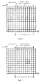
- Fig. 3 is a schematic diagram of a first pilot pattern according to an embodiment of the invention.
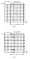
- Fig. 4 is a first schematic diagram of a second pilot pattern according to an embodiment of the invention.
- Fig. 5 is a second schematic diagram of a second pilot pattern according to an embodiment of the invention.
- Fig. 6 is a first schematic diagram of a third pilot pattern according to an embodiment of the invention.
- Fig. 7 is a second schematic diagram of a third pilot pattern according to an embodiment of the invention.
- Fig. 8 is a first schematic diagram of a fourth pilot pattern according to an embodiment of the invention.
- Fig. 9 is a second schematic diagram of a fourth pilot pattern according to an embodiment of the invention.
- Fig. 10 is a first schematic diagram of a fifth pilot pattern according to an embodiment of the invention.
- Fig. 11 is a second schematic diagram of a fifth pilot pattern according to an embodiment of the invention.
- Fig. 12 is a first schematic diagram of a sixth pilot pattern according to an embodiment of the invention.
- Fig. 13 is a second schematic diagram of a sixth pilot pattern according to an embodiment of the invention.
- Fig. 14 is a first schematic diagram of a seventh pilot pattern according to an embodiment of the invention.
- Fig. 15 is a second schematic diagram of a seventh pilot pattern according to an embodiment of the invention.
- Fig. 16 is a schematic composition diagram of a wireless communication system according to an embodiment of the invention.
- Fig. 17 is a schematic structural diagram of an eNB according to an embodiment of the invention.
- Fig. 18 is a schematic structural diagram of a relay node according to an embodiment of the invention.
- an eNB carries a Common Reference Signal (CRS) or a Demodulation Reference Signal (DMRS), over a carrier over which a data signal and/or a control signal is transmitted to an RN, after the end of a guard interval TRG and before the start of a guard interval RTG, and the RN demodulates the signal transmitted from the eNB according to the CRS or the DMRS, where the TRG is a guard interval for the relay node RN to transform from transmitting a signal to receiving a signal over a backhaul link, and the RTG is a guard interval for the RN to transform from receiving a signal to transmitting a signal over the backhaul link.
- CRS Common Reference Signal
- DMRS Demodulation Reference Signal
- the CRS or the DMRS is carried over the carrier, over which a data signal and/or a control signal is transmitted to the RN, and used as a pilot signal to demodulate the data signal and/or the control signal so that the RN can demodulate correctly the received data signal and/or control signal according to the CRS or the DMRS.
- the CRS and the DMRS are filled in an OFDM symbol period between the end of the TRG and the start of the RTG instead of being filled in the TRG and the RTG, so the TRG and the RTG will not be structurally corrupted, making it possible to further ensure correct reception by the RN of the data signal and/or the control signal from the eNB.
- the TRG occupies the 2 nd , 3 rd and 4 th OFDM symbols arranged sequentially in a temporal order in a Physical Resource Block (PRB) pair, and the RTG occupies the 14 th OFDM symbol arranged sequentially in the temporal order in the PRB pair.
- PRB Physical Resource Block
- An embodiment of the invention presents a specific solution to a specific time and frequency at which, that is, a corresponding pilot pattern in which, the eNB fills the CRS and the DMRS after the end of the TRG and before the start of the RTG. Pilot patterns according to embodiments of the invention will be introduced below with reference to the drawings.
- Fig. 3 is a schematic diagram of a first pilot pattern according to an embodiment of the invention.
- the abscissa represents time in a unit with a length of one OFDM symbol
- the ordinate represents frequency in a unit with a length of a frequency resource occupied for one carrier.
- the eNB carries a CRS as a pilot signal over a carrier over which a data signal and/or a control signal is transmitted to the RN, particularly carries a CRS in each of the 1 st , 4 th , 5 th and 8 th OFDM symbols after the end of the TRG, and carries a CRS over each of the 1 st , 4 th , 7 th and 10 th carriers in an ascending order of the frequencies of respective carriers in a PRB pair, in each of the OFDM symbols with the CRSs to be carried therein, that is, the 1 st , 4 th , 5 th and 8 th OFDM symbols after the end of the TRG.
- the TRG can occupy the 2 nd , 3 rd and 4 th OFDM symbols over all the carriers; and an RTG can occupy the 14 th OFDM symbol over all the carriers.
- Fig. 4 and Fig. 5 are schematic diagrams of a second pilot pattern according to an embodiment of the invention, where Fig. 4 shows a pilot pattern when the eNB adopts single-stream transmission or dual-stream transmission, and Fig. 5 shows a pilot pattern when the eNB adopts three-stream transmission or four-stream transmission.
- the eNB carries a DMRS as a pilot signal over a carrier over which a data signal and/or a control signal is transmitted to the RN, particularly carries a DMRS in each of the 2 nd and 3 rd OFDM symbols after the end of the TRG, and in each of the OFDM symbols with the DMRSs to be carried therein, the eNB carries a DMRS over the 7 th carrier in an ascending order of the frequencies of respective carriers in a PRB pair as illustrated in Fig.
- the eNB adopts single-stream transmission or dual-stream transmission, or the eNB carries a DMRS over each of the 6 th and 7 th carriers in an ascending order of the frequencies of respective carriers in a PRB pair as illustrated in Fig. 5 if the eNB adopts three-stream or four-stream transmission of a data signal and/or a control signal.
- Fig. 6 and Fig. 7 are schematic diagrams of a third pilot pattern according to an embodiment of the invention, where Fig. 6 shows a pilot pattern when the eNB adopts single-stream transmission or dual-stream transmission, and Fig. 5 shows a pilot pattern when the eNB adopts three-stream transmission or four-stream transmission.
- the eNB carries a DMRS in each of the 2 nd , 3 rd , 6 th and 7 th OFDM symbols after the end of the TRG, and in each of the OFDM symbols with the DMRSs to be carried therein, the eNB carries a DMRS over the 7 th carrier in an ascending order of the frequencies of respective carriers in a PRB pair as illustrated in Fig. 6 if the eNB adopts single-stream transmission or dual-stream transmission, or the eNB carries a DMRS over each of the 6 th and 7 th carriers in an ascending order of the frequencies of respective carriers in a PRB pair as illustrated in Fig. 7 if the eNB adopts three-stream or four-stream transmission of a data signal and/or a control signal.
- Fig. 8 and Fig. 9 are schematic diagrams of a fourth pilot pattern according to an embodiment of the invention, where Fig. 8 shows a pilot pattern when the eNB adopts single-stream transmission or dual-stream transmission, and Fig. 9 shows a pilot pattern when the eNB adopts three-stream transmission or four-stream transmission.
- the eNB carries a DMRS in each of the 2 nd and 3 rd OFDM symbols after the end of the TRG, and in each of the OFDM symbols with the DMRSs to be carried therein, the eNB carries a DMRS over each of the 2 nd and 12 th carriers in an ascending order of the frequencies of respective carriers in a PRB pair as illustrated in Fig. 8 if the eNB adopts single-stream transmission or dual-stream transmission, or the eNB carries a DMRS over each of the 1 st , 2 nd , 11 th and 12 th carriers in an ascending order of the frequencies of respective carriers in a PRB pair as illustrated in Fig. 9 if the eNB adopts three-stream or four-stream transmission of a data signal and/or a control signal.
- Fig. 10 and Fig. 11 are schematic diagrams of a fifth pilot pattern according to an embodiment of the invention, where Fig. 10 shows a pilot pattern when the eNB adopts single-stream transmission or dual-stream transmission, and Fig. 11 shows a pilot pattern when the eNB adopts three-stream transmission or four-stream transmission.
- the eNB carries a DMRS in each of the 2 nd , 3 rd , 6 th and 7 th OFDM symbols after the end of the TRG, and in each of the OFDM symbols with the DMRSs to be carried therein, the eNB carries a DMRS over each of the 2 nd and 12 th carriers in an ascending order of the frequencies of respective carriers in a PRB pair as illustrated in Fig.
- the eNB adopts single-stream transmission or dual-stream transmission, or the eNB carries a DMRS over each of the 1 st , 2 nd , 11 th and 12 th carriers in an ascending order of the frequencies of respective carriers in a PRB pair as illustrated in Fig. 11 if the eNB adopts three-stream or four-stream transmission of a data signal and/or a control signal.
- Fig. 12 and Fig. 13 are schematic diagrams of a sixth pilot pattern according to an embodiment of the invention, where Fig. 12 shows a pilot pattern when the eNB adopts single-stream transmission or dual-stream transmission, and Fig. 13 shows a pilot pattern when the eNB adopts three-stream transmission or four-stream transmission.
- the eNB carries a DMRS in each of the 2 nd and 3 rd OFDM symbols after the end of the TRG, and in each of the OFDM symbols with the DMRSs to be carried therein, the eNB carries a DMRS over each of the 2 nd , 7 th and 12 th carriers in an ascending order of the frequencies of respective carriers in a PRB pair as illustrated in Fig.
- the eNB adopts single-stream transmission or dual-stream transmission, or the eNB carries a DMRS over each of the 1 st , 2 nd , 6 th , 7 th , 11 th and 12 th carriers in an ascending order of the frequencies of respective carriers in a PRB pair as illustrated in Fig. 13 if the eNB adopts three-stream or four-stream transmission of a data signal and/or a control signal.
- Fig. 14 and Fig. 15 are schematic diagrams of a seven pilot pattern according to an embodiment of the invention, where Fig. 12 shows a pilot pattern when the eNB adopts single-stream transmission or dual-stream transmission, and Fig. 13 shows a pilot pattern when the eNB adopts three-stream transmission or four-stream transmission.
- the eNB carries a DMRS in each of the 2 nd , 3 rd , 6 th and 7 th OFDM symbols after the end of the TRG, and in each of the OFDM symbols with the DMRSs to be carried therein, the eNB carries a DMRS over each of the 2 nd , 7 th and 12 th carriers in an ascending order of the frequencies of respective carriers in a PRB pair as illustrated in Fig.
- the eNB adopts single-stream transmission or dual-stream transmission, or the eNB carries a DMRS over each of the 1 st , 2 nd , 6 th , 7 th , 11 th and 12 th carriers in an ascending order of the frequencies of respective carriers in a PRB pair as illustrated in Fig. 15 if the eNB adopts three-stream or four-stream transmission of a data signal and/or a control signal.
- pilot signals are distributed over corresponding carriers as uniformly as possible according to the density of the pilot signals and the frequencies of the carriers, and when the eNB and the RN perform wireless communication in the pilot pattern, the RN can well demodulate a data signal and/or a control signal transmitted from the eNB due to uniform distribution of the pilot signals to thereby improve correctness of demodulating the signal.
- a DMRS is carried in the 7 th carrier in an ascending order of frequencies in a PRB pair, and since the frequency of the 7 th carrier is centrally located among the frequencies of respective carriers in the PRB pair and there is a smaller difference in frequency between each of the other carriers and the 7 th carrier, thus there is a higher correctness ratio of signal demodulation with the DMRS carried over the 7 th carrier.
- a DMRS is carried in each of the 2 nd and 12 th carriers in an ascending order of frequencies in a PRB pair, and for demodulation of a data signal and/or a control signal over a carrier at a centrally arranged frequency (e.g., the 6 th or 7 th carrier), the DMRSs carried over the 2 nd and 12 th carriers can be interpolated to thereby improve the correctness ratio of signal demodulation.
- a centrally arranged frequency e.g., the 6 th or 7 th carrier
- an embodiment of the invention further provides a radio communication system, and reference can be made to Fig. 16 for details thereof.
- Fig. 16 is a schematic composition diagram of a wireless communication system according to an embodiment of the invention.
- the wireless communication system includes an eNB and an RN.
- the eNB carries a CRS or a DMRS over a carrier over which a data signal and/or a control signal is transmitted to the RN, in a period after the end of a guard interval TRG and before the start of a guard interval RTG, where the TRG is a guard interval for the RN to transform from transmitting a signal to receiving a signal over a backhaul link, and the RTG is a guard interval for the RN to transform from receiving a signal to transmitting a signal over the backhaul link.
- the RN demodulates the data signal and/or the control signal transmitted from the eNB according to the received CRS or the DMRS.
- the TRG occupies the 2 nd , 3 rd and 4 th OFDM symbols arranged sequentially in a temporal order in a PRB pair, and the RTG occupies the 14 th OFDM symbol arranged sequentially in the temporal order in the PRB pair.
- the eNB When the eNB carries the CRS over the carrier over which the data signal and/or the control signal is transmitted to the RN, the eNB carries the CRS in each of the 1 st , 4 th , 5 th and 8 th OFDM symbols after the end of the TRG, and carries the CRS over each of the 1 st , 4 th , 7 th and 10 th carriers in an ascending order of the frequencies of respective carriers in a PRB pair, in each of the OFDM symbols with the CRSs to be carried therein.
- the eNB When the eNB carries the DMRS over the carrier over which the data signal and/or the control signal is transmitted to the RN, the eNB carries the DMRS in each of the 2 nd and 3 rd OFDM symbols after the end of the TRG, and carries the DMRS over the 7 th carrier or each of the 6 th and 7 th carriers in an ascending order of the frequencies of respective carriers in a PRB pair, in each of the OFDM symbols with the DMRSs to be carried therein; or the eNB carries the DMRS in each of the 2 nd , 3 rd , 6 th and 7 th OFDM symbols after the end of the TRG, and carries the DMRS over the 7 th carrier or each of the 6 th and the 7 th carriers in an ascending order of the frequencies of respective carriers in a PRB pair, in each of the OFDM symbols with the DMRSs to be carried therein; or the eNB carries the DMRS in each of the 2
- embodiments of the invention further provide an eNB and a relay node, and reference can be made to Fig. 17 and Fig. 18 for details thereof.
- Fig. 17 is a schematic structural diagram of an eNB according to an embodiment of the invention.
- the eNB includes a signal filling module 1701 and a transmitting module 1702.
- the signal filling module 1701 carries a CRS or a DMRS, over a carrier over which a signal is transmitted to an RN, after the end of a guard interval TRG and before the start of a guard interval RTG, where the TRG is a guard interval for the RN to transform from transmitting a signal to receiving a signal over a backhaul link, and the RTG is a guard interval for the RN to transform from receiving a signal to transmitting a signal over the backhaul link.
- the transmitting module 1702 transmits a data signal and/or a control signal to the RN over the carrier over which the CRS or the DMRS is carried.
- the TRG occupies the 2 nd , 3 rd and 4 th OFDM symbols arranged sequentially in a temporal order in a PRB pair, and the RTG occupies the 14 th OFDM symbol arranged sequentially in the temporal order in the PRB pair.
- the signal filling module 1701 carries the CRS over the carrier over which the data signal and/or the control signal is transmitted to the RN by carrying the CRS in each of the 1 st , 4 th , 5 th and 8 th OFDM symbols after the end of the TRG, and carrying the CRS over each of the 1 st , 4 th , 7 th and 10 th carriers in an ascending order of the frequencies of respective carriers in a Physical Resource Block (PRB) pair, in each of the OFDM symbols with the CRSs to be carried therein.
- PRB Physical Resource Block
- the signal filling module 1701 When the signal filling module 1701 carries the DMRS over the carrier over which the data signal and/or the control signal is transmitted to the RN, the signal filling module carries the DMRS in each of the 2 nd and 3 rd OFDM symbols after the end of the TRG, and carries the DMRS over the 7 th carrier or each of the 6 th and 7 th carriers in an ascending order of the frequencies of respective carriers in a PRB pair, in each of the OFDM symbols with the DMRSs to be carried therein; or the signal filling module carries the DMRS in each of the 2 nd , 3 rd , 6 th and 7 th OFDM symbols after the end of the TRG, and carries the DMRS over the 7 th carrier or each of the 6 th and the 7 th carriers in an ascending order of the frequencies of respective carriers in a PRB pair, in each of the OFDM symbols with the DMRSs to be carried therein; or the signal filling module carries
- Fig. 18 is a schematic structural diagram of a relay node according to an embodiment of the invention.
- the relay node includes a receiving module 1801 and a signal demodulating module 1802.
- the receiving module 1801 receives a CRS or a DMRS carried over a carrier, over which a data signal and/or a control signal is transmitted, by an eNB, in a period after the end of a guard interval TRG and before the start of a guard interval RTG, where the TRG is a guard interval for the relay node to transform from transmitting a signal to receiving a signal over a backhaul link, and the RTG is a guard interval for the relay node to transform from receiving a signal to transmitting a signal over the backhaul link.
- the signal demodulating module 1802 demodulates the data signal and/or the control signal transmitted from the eNB according to the received CRS or DMRS.
- the TRG occupies the 2 nd , 3 rd and 4 th OFDM symbols arranged sequentially in a temporal order in a PRB pair, and the RTG occupies the 14 th OFDM symbol arranged sequentially in the temporal order in the PRB pair.
- the receiving module 1801 receives the CRS over each of the 1 st , 4 th , 7 th and 10 th carriers in an ascending order of the frequencies of respective carriers in a Physical Resource Block (PRB) pair, in each of the 1 st , 4 th , 5 th and 8 th OFDM symbols after the end of the TRG; or receives the DMRS over the 7 th carrier or each of the 6 th and 7 th carriers in an ascending order of the frequencies of respective carriers in a PRB pair, in each of the 2 nd and 3 rd OFDM symbols after the end of the TRG; or receives the DMRS over the 7 th carrier or each of the 6 th and the 7 th carriers in an ascending order of the frequencies of respective carriers in a PRB pair, in each of the 2 nd , 3 rd , 6 th and 7 th OFDM symbols after the end of the TRG; or receives the DMRS over each of the 2 nd and 12 th or the 1
- the embodiments of the invention can be embodied as a method, a system or a computer program product. Therefore the invention can be embodied in the form of an all-hardware embodiment, an all-software embodiment or an embodiment of software and hardware in combination. Furthermore, the invention can be embodied in the form of a computer program product embodied in one or more computer useable storage mediums (including but not limited to a disk memory, a CD-ROM, an optical memory, etc.) in which computer useable program codes are contained.
- a computer useable storage mediums including but not limited to a disk memory, a CD-ROM, an optical memory, etc.
- These computer program instructions can also be stored into a computer readable memory capable of directing the computer or the other programmable data processing device to operate in a specific manner so that the instructions stored in the computer readable memory create an article of manufacture including instruction means which perform the functions specified in the flow(s) of the flow chart and/or the block(s) of the block diagram.
- These computer program instructions can also be loaded onto the computer or the other programmable data processing device so that a series of operational steps are performed on the computer or the other programmable data processing device to create a computer implemented process so that the instructions executed on the computer or the other programmable data processing device provide steps for performing the functions specified in the flow(s) of the flow chart and/or the block(s) of the block diagram.
Landscapes
- Engineering & Computer Science (AREA)
- Signal Processing (AREA)
- Computer Networks & Wireless Communication (AREA)
- Mobile Radio Communication Systems (AREA)
Abstract
Description
- The present application claims priority to Chinese Patent Application No.
201010144375.7 - The present invention relates to the field of mobile communications and particularly to a method, system and device for wireless communication.
- Information is required to be transmitted at a high rate in a future mobile communication system, for example, the rate at which information is transmitted is up to 1 Giga bit per second (Gbit/s). Since a larger bandwidth and a higher carrier frequency have to be occupied for transmission of information at a high rate, only a hot spot can be covered due to a considerable path loss in some edge area of a cell, so transmission of information at a high rate can not be ensured in the edge area of the cell. In this case, high-rate information from a base station can be forwarded by means of the technology of Relay Node (RN) to thereby improve a coverage area of information transmission at a high rate from the base station. Apparently, the RN technology is an effective solution to a further extended coverage area of information transmission at a high rate and expanded capacity of a cellular system.
-
Fig. 1 is a schematic composition diagram of an existing mobile communication system with an RN. - Referring to
Fig. 1 , an information transmission link of the system illustrated inFig. 1 is divided into two hops, i.e., an access link and a backhaul link. The access link refers to a Transmission Time Interval (TTI) for transmission of information between an evolved Node B (eNB) and a User Equipment (UE) and a TTI for transmission of information between the RN and the UE. The backhaul link refers to a TTI for transmission of information between the eNB and the RN, where the information between the eNB and the RN and the information between the eNB and the UE can be transmitted in the same TTI. -
Fig. 2 is a schematic structural diagram of an existing frame over a backhaul link of an RN. - In
Fig. 2 , the abscissa represents time and the ordinate represents frequency. InFig. 2 , a Transmit-Receive Guard (TRG) is a guard interval required by the RN from transmitting a signal to receiving a signal over the backhaul link, and the TRG occupies the 2nd, 3rd and 4th Orthogonal Frequency Division Multiplexing (OFDM) symbols of all the carriers; and a Receive-Transmit Guard (RTG) is a guard interval required by the RN from receiving a signal to transmitting a signal over the backhaul link, and the RTG occupies the 14th OFDM symbol period of all the carriers. The RN remains in a silent state over the access link, that is, it neither receives a data signal nor transmits a data signal, in a temporal range between the TRG and the RTG, i.e., in a short Cyclic Prefix (CP) backhaul link TTI or a short eNB-Relay TTI. Particularly, the RTG is necessary only for absolute synchronization between the RN and the eNB, and if no absolute synchronization is required between the RN and the eNB, the RTG may not be set inFig. 2 , that is, no guard interval is required to be set for the RN from receiving a signal to transmitting a signal over the backhaul link. - The RN receives a data signal and/or a control signal from the eNB after the end of the TRG and before the start of the RTG. A specific solution to how the RN can receive correctly a data signal and/or a control signal transmitted from the eNB has been absent so far in the prior art.
- In view of this, the invention provides a method, system and device for wireless communication, so that an RN can receive correctly a data signal and/or a control signal transmitted from an eNB.
- Technical solutions of the invention are embodied as follows.
- There is a wireless communication method including: carrying, by an evolved Node B (eNB), a Common Reference Signal (CRS) or a Demodulation Reference Signal (DMRS) over a carrier over which a data signal and/or a control signal is transmitted to a Relay Node (RN) after the end of a guard interval TRG and before the start of a guard interval RTG, wherein the TRG is a guard interval for the RN to transform from transmitting a signal to receiving a signal over a backhaul link, and the RTG is a guard interval for the RN to transform from receiving a signal to transmitting a signal over the backhaul link; and demodulating, by the RN, the signal transmitted from the eNB according to the CRS or the DMRS.
- There is a wireless communication system including an evolved Node B (eNB) and a Relay Node (RN), wherein the eNB is configured to carry a Common Reference Signal (CRS) or a Demodulation Reference Signal (DMRS) over a carrier over which a data signal and/or a control signal is transmitted to the RN, in a period after the end of a guard interval TRG and before the start of a guard interval RTG, wherein the TRG is a guard interval for the RN to transform from transmitting a signal to receiving a signal over a backhaul link, and the RTG is a guard interval for the RN to transform from receiving a signal to transmitting a signal over the backhaul link; and the RN is configured to demodulate the data signal and/or the control signal transmitted from the eNB according to the received CRS or the DMRS.
- There is an evolved Node B including a signal filling module and a transmitting module, wherein the signal filling module is configured to carry a Common Reference Signal (CRS) or a Demodulation Reference Signal (DMRS) over a carrier over which a data signal and/or a control signal is transmitted to a Relay Node (RN), after the end of a guard interval TRG and before the start of a guard interval RTG, wherein the TRG is a guard interval for the RN to transform from transmitting a signal to receiving a signal over a backhaul link, and the RTG is a guard interval for the RN to transform from receiving a signal to transmitting a signal over the backhaul link; and the transmitting module is configured to transmit the data signal and/or the control signal to the RN over the carrier over which the CRS or the DMRS is carried.
- There is a relay node including a receiving module and a signal demodulation module, wherein the receiving module is configured to receive a Common Reference Signal (CRS) or a Demodulation Reference Signal (DMRS) carried over a carrier, over which a data signal and/or a control signal is transmitted, by an evolved Node B (eNB), in a period after the end of a guard interval TRG and before the start of a guard interval RTG, wherein the TRG is a guard interval for the relay node to transform from transmitting a signal to receiving a signal over a backhaul link, and the RTG is a guard interval for the relay node to transform from receiving a signal to transmitting a signal over the backhaul link; and the signal demodulating module is configured to demodulate the data signal and/or the control signal transmitted from the eNB according to the received CRS or DMRS.
- In the embodiments of the invention, the eNB carries a CRS or a DMRS over a carrier, over which a data signal and/or a control signal is transmitted to the RN, after the end of a guard interval TRG and before the start of a guard interval RTG, so that the RN can demodulate the data signal and/or the control signal according to the CRS or the DMRS, and thus the RN can receive correctly the data signal and/or the control signal transmitted from the eNB. Moreover, the CRS and the DMRS are filled in OFDM symbols between the end of the TRG and the start of the RTG, so the TRG and the RTG will not be structurally corrupted, thereby further ensuring correct reception by the RN of the data signal and/or the control signal from the eNB.
-
Fig. 1 is a schematic composition diagram of an existing mobile communication system with an RN; -
Fig. 2 is a schematic structural diagram of an existing frame over a backhaul link of an RN; -
Fig. 3 is a schematic diagram of a first pilot pattern according to an embodiment of the invention; -
Fig. 4 is a first schematic diagram of a second pilot pattern according to an embodiment of the invention; -
Fig. 5 is a second schematic diagram of a second pilot pattern according to an embodiment of the invention; -
Fig. 6 is a first schematic diagram of a third pilot pattern according to an embodiment of the invention; -
Fig. 7 is a second schematic diagram of a third pilot pattern according to an embodiment of the invention; -
Fig. 8 is a first schematic diagram of a fourth pilot pattern according to an embodiment of the invention; -
Fig. 9 is a second schematic diagram of a fourth pilot pattern according to an embodiment of the invention; -
Fig. 10 is a first schematic diagram of a fifth pilot pattern according to an embodiment of the invention; -
Fig. 11 is a second schematic diagram of a fifth pilot pattern according to an embodiment of the invention; -
Fig. 12 is a first schematic diagram of a sixth pilot pattern according to an embodiment of the invention; -
Fig. 13 is a second schematic diagram of a sixth pilot pattern according to an embodiment of the invention; -
Fig. 14 is a first schematic diagram of a seventh pilot pattern according to an embodiment of the invention; -
Fig. 15 is a second schematic diagram of a seventh pilot pattern according to an embodiment of the invention; -
Fig. 16 is a schematic composition diagram of a wireless communication system according to an embodiment of the invention; -
Fig. 17 is a schematic structural diagram of an eNB according to an embodiment of the invention; and -
Fig. 18 is a schematic structural diagram of a relay node according to an embodiment of the invention. - In a wireless communication method according to an embodiment of the invention, an eNB carries a Common Reference Signal (CRS) or a Demodulation Reference Signal (DMRS), over a carrier over which a data signal and/or a control signal is transmitted to an RN, after the end of a guard interval TRG and before the start of a guard interval RTG, and the RN demodulates the signal transmitted from the eNB according to the CRS or the DMRS, where the TRG is a guard interval for the relay node RN to transform from transmitting a signal to receiving a signal over a backhaul link, and the RTG is a guard interval for the RN to transform from receiving a signal to transmitting a signal over the backhaul link.
- In the embodiment of the invention, the CRS or the DMRS is carried over the carrier, over which a data signal and/or a control signal is transmitted to the RN, and used as a pilot signal to demodulate the data signal and/or the control signal so that the RN can demodulate correctly the received data signal and/or control signal according to the CRS or the DMRS.
- Moreover, the CRS and the DMRS are filled in an OFDM symbol period between the end of the TRG and the start of the RTG instead of being filled in the TRG and the RTG, so the TRG and the RTG will not be structurally corrupted, making it possible to further ensure correct reception by the RN of the data signal and/or the control signal from the eNB.
- In an embodiment of the invention, the TRG occupies the 2nd, 3rd and 4th OFDM symbols arranged sequentially in a temporal order in a Physical Resource Block (PRB) pair, and the RTG occupies the 14th OFDM symbol arranged sequentially in the temporal order in the PRB pair.
- An embodiment of the invention presents a specific solution to a specific time and frequency at which, that is, a corresponding pilot pattern in which, the eNB fills the CRS and the DMRS after the end of the TRG and before the start of the RTG. Pilot patterns according to embodiments of the invention will be introduced below with reference to the drawings.
-
Fig. 3 is a schematic diagram of a first pilot pattern according to an embodiment of the invention. - In
Fig. 3 , the abscissa represents time in a unit with a length of one OFDM symbol, and the ordinate represents frequency in a unit with a length of a frequency resource occupied for one carrier. - In
Fig. 3 , the eNB carries a CRS as a pilot signal over a carrier over which a data signal and/or a control signal is transmitted to the RN, particularly carries a CRS in each of the 1st, 4th, 5th and 8th OFDM symbols after the end of the TRG, and carries a CRS over each of the 1st, 4th, 7th and 10th carriers in an ascending order of the frequencies of respective carriers in a PRB pair, in each of the OFDM symbols with the CRSs to be carried therein, that is, the 1st, 4th, 5th and 8th OFDM symbols after the end of the TRG. - The TRG can occupy the 2nd, 3rd and 4th OFDM symbols over all the carriers; and an RTG can occupy the 14th OFDM symbol over all the carriers.
-
Fig. 4 and Fig. 5 are schematic diagrams of a second pilot pattern according to an embodiment of the invention, whereFig. 4 shows a pilot pattern when the eNB adopts single-stream transmission or dual-stream transmission, andFig. 5 shows a pilot pattern when the eNB adopts three-stream transmission or four-stream transmission. - In
Fig. 4 and Fig. 5 , the eNB carries a DMRS as a pilot signal over a carrier over which a data signal and/or a control signal is transmitted to the RN, particularly carries a DMRS in each of the 2nd and 3rd OFDM symbols after the end of the TRG, and in each of the OFDM symbols with the DMRSs to be carried therein, the eNB carries a DMRS over the 7th carrier in an ascending order of the frequencies of respective carriers in a PRB pair as illustrated inFig. 4 if the eNB adopts single-stream transmission or dual-stream transmission, or the eNB carries a DMRS over each of the 6th and 7th carriers in an ascending order of the frequencies of respective carriers in a PRB pair as illustrated inFig. 5 if the eNB adopts three-stream or four-stream transmission of a data signal and/or a control signal. -
Fig. 6 and Fig. 7 are schematic diagrams of a third pilot pattern according to an embodiment of the invention, whereFig. 6 shows a pilot pattern when the eNB adopts single-stream transmission or dual-stream transmission, andFig. 5 shows a pilot pattern when the eNB adopts three-stream transmission or four-stream transmission. - In
Fig. 6 and Fig. 7 , the eNB carries a DMRS in each of the 2nd, 3rd, 6th and 7th OFDM symbols after the end of the TRG, and in each of the OFDM symbols with the DMRSs to be carried therein, the eNB carries a DMRS over the 7th carrier in an ascending order of the frequencies of respective carriers in a PRB pair as illustrated inFig. 6 if the eNB adopts single-stream transmission or dual-stream transmission, or the eNB carries a DMRS over each of the 6th and 7th carriers in an ascending order of the frequencies of respective carriers in a PRB pair as illustrated inFig. 7 if the eNB adopts three-stream or four-stream transmission of a data signal and/or a control signal. -
Fig. 8 and Fig. 9 are schematic diagrams of a fourth pilot pattern according to an embodiment of the invention, whereFig. 8 shows a pilot pattern when the eNB adopts single-stream transmission or dual-stream transmission, andFig. 9 shows a pilot pattern when the eNB adopts three-stream transmission or four-stream transmission. - In
Fig. 8 and Fig. 9 , the eNB carries a DMRS in each of the 2nd and 3rd OFDM symbols after the end of the TRG, and in each of the OFDM symbols with the DMRSs to be carried therein, the eNB carries a DMRS over each of the 2nd and 12th carriers in an ascending order of the frequencies of respective carriers in a PRB pair as illustrated inFig. 8 if the eNB adopts single-stream transmission or dual-stream transmission, or the eNB carries a DMRS over each of the 1st, 2nd, 11th and 12th carriers in an ascending order of the frequencies of respective carriers in a PRB pair as illustrated inFig. 9 if the eNB adopts three-stream or four-stream transmission of a data signal and/or a control signal. -
Fig. 10 and Fig. 11 are schematic diagrams of a fifth pilot pattern according to an embodiment of the invention, whereFig. 10 shows a pilot pattern when the eNB adopts single-stream transmission or dual-stream transmission, andFig. 11 shows a pilot pattern when the eNB adopts three-stream transmission or four-stream transmission. - In
Fig. 10 and Fig. 11 , the eNB carries a DMRS in each of the 2nd, 3 rd, 6th and 7th OFDM symbols after the end of the TRG, and in each of the OFDM symbols with the DMRSs to be carried therein, the eNB carries a DMRS over each of the 2nd and 12th carriers in an ascending order of the frequencies of respective carriers in a PRB pair as illustrated inFig. 10 if the eNB adopts single-stream transmission or dual-stream transmission, or the eNB carries a DMRS over each of the 1st, 2nd, 11th and 12th carriers in an ascending order of the frequencies of respective carriers in a PRB pair as illustrated inFig. 11 if the eNB adopts three-stream or four-stream transmission of a data signal and/or a control signal. -
Fig. 12 and Fig. 13 are schematic diagrams of a sixth pilot pattern according to an embodiment of the invention, whereFig. 12 shows a pilot pattern when the eNB adopts single-stream transmission or dual-stream transmission, andFig. 13 shows a pilot pattern when the eNB adopts three-stream transmission or four-stream transmission. - In
Fig. 12 and Fig. 13 , the eNB carries a DMRS in each of the 2nd and 3rd OFDM symbols after the end of the TRG, and in each of the OFDM symbols with the DMRSs to be carried therein, the eNB carries a DMRS over each of the 2nd, 7th and 12th carriers in an ascending order of the frequencies of respective carriers in a PRB pair as illustrated inFig. 12 if the eNB adopts single-stream transmission or dual-stream transmission, or the eNB carries a DMRS over each of the 1st, 2nd, 6th, 7th, 11th and 12th carriers in an ascending order of the frequencies of respective carriers in a PRB pair as illustrated inFig. 13 if the eNB adopts three-stream or four-stream transmission of a data signal and/or a control signal. -
Fig. 14 and Fig. 15 are schematic diagrams of a seven pilot pattern according to an embodiment of the invention, whereFig. 12 shows a pilot pattern when the eNB adopts single-stream transmission or dual-stream transmission, andFig. 13 shows a pilot pattern when the eNB adopts three-stream transmission or four-stream transmission. - In
Fig. 14 and Fig. 15 , the eNB carries a DMRS in each of the 2nd, 3rd , 6th and 7th OFDM symbols after the end of the TRG, and in each of the OFDM symbols with the DMRSs to be carried therein, the eNB carries a DMRS over each of the 2nd, 7th and 12th carriers in an ascending order of the frequencies of respective carriers in a PRB pair as illustrated inFig. 14 if the eNB adopts single-stream transmission or dual-stream transmission, or the eNB carries a DMRS over each of the 1st, 2nd, 6th, 7th, 11th and 12th carriers in an ascending order of the frequencies of respective carriers in a PRB pair as illustrated inFig. 15 if the eNB adopts three-stream or four-stream transmission of a data signal and/or a control signal. - In a pilot pattern according to an embodiment of the invention, pilot signals are distributed over corresponding carriers as uniformly as possible according to the density of the pilot signals and the frequencies of the carriers, and when the eNB and the RN perform wireless communication in the pilot pattern, the RN can well demodulate a data signal and/or a control signal transmitted from the eNB due to uniform distribution of the pilot signals to thereby improve correctness of demodulating the signal.
- In the pilot patterns illustrated in
Fig. 4 and Fig. 5 , for example, a DMRS is carried in the 7th carrier in an ascending order of frequencies in a PRB pair, and since the frequency of the 7th carrier is centrally located among the frequencies of respective carriers in the PRB pair and there is a smaller difference in frequency between each of the other carriers and the 7th carrier, thus there is a higher correctness ratio of signal demodulation with the DMRS carried over the 7th carrier. - In another example, in the pilot patterns illustrated in
Fig. 8 and Fig. 9 , a DMRS is carried in each of the 2nd and 12th carriers in an ascending order of frequencies in a PRB pair, and for demodulation of a data signal and/or a control signal over a carrier at a centrally arranged frequency (e.g., the 6th or 7th carrier), the DMRSs carried over the 2nd and 12th carriers can be interpolated to thereby improve the correctness ratio of signal demodulation. - Following the foregoing wireless communication method, an embodiment of the invention further provides a radio communication system, and reference can be made to
Fig. 16 for details thereof. -
Fig. 16 is a schematic composition diagram of a wireless communication system according to an embodiment of the invention. - As illustrated in
Fig. 16 , the wireless communication system includes an eNB and an RN. - The eNB carries a CRS or a DMRS over a carrier over which a data signal and/or a control signal is transmitted to the RN, in a period after the end of a guard interval TRG and before the start of a guard interval RTG, where the TRG is a guard interval for the RN to transform from transmitting a signal to receiving a signal over a backhaul link, and the RTG is a guard interval for the RN to transform from receiving a signal to transmitting a signal over the backhaul link.
- The RN demodulates the data signal and/or the control signal transmitted from the eNB according to the received CRS or the DMRS.
- The TRG occupies the 2nd, 3rd and 4th OFDM symbols arranged sequentially in a temporal order in a PRB pair, and the RTG occupies the 14th OFDM symbol arranged sequentially in the temporal order in the PRB pair.
- When the eNB carries the CRS over the carrier over which the data signal and/or the control signal is transmitted to the RN, the eNB carries the CRS in each of the 1st, 4th, 5th and 8th OFDM symbols after the end of the TRG, and carries the CRS over each of the 1st, 4th, 7th and 10th carriers in an ascending order of the frequencies of respective carriers in a PRB pair, in each of the OFDM symbols with the CRSs to be carried therein.
- When the eNB carries the DMRS over the carrier over which the data signal and/or the control signal is transmitted to the RN, the eNB carries the DMRS in each of the 2nd and 3rd OFDM symbols after the end of the TRG, and carries the DMRS over the 7th carrier or each of the 6th and 7th carriers in an ascending order of the frequencies of respective carriers in a PRB pair, in each of the OFDM symbols with the DMRSs to be carried therein; or the eNB carries the DMRS in each of the 2nd, 3rd, 6th and 7th OFDM symbols after the end of the TRG, and carries the DMRS over the 7th carrier or each of the 6th and the 7th carriers in an ascending order of the frequencies of respective carriers in a PRB pair, in each of the OFDM symbols with the DMRSs to be carried therein; or the eNB carries the DMRS in each of the 2nd and 3rd OFDM symbols after the end of the TRG, and carries the DMRS over each of the 2nd and 12th or the 1st, 2nd, 11th and 12th carriers in an ascending order of the frequencies of respective carriers in a PRB pair, in each of the OFDM symbols with the DMRSs to be carried therein; or the eNB carries the DMRS in each of the 2nd, 3rd, 6th and 7th OFDM symbols after the end of the TRG, and carries the DMRS over each of the 2nd and 12th or the 1st, 2nd, 11th and 12th carriers in an ascending order of the frequencies of respective carriers in a PRB pair, in each of the OFDM symbols with the DMRSs to be carried therein; or the eNB carries the DMRS in each of the 2nd and 3rd OFDM symbols after the end of the TRG, and carries the DMRS over each of the 2nd, 7th and 12th or the 1st, 2nd, 6th, 7th, 11th and 12th carriers in an ascending order of the frequencies of respective carriers in a PRB pair, in each of the OFDM symbols with the DMRSs to be carried therein; or the eNB carries the DMRS in each of the 2nd, 3rd, 6th and 7th OFDM symbols after the end of the TRG, and carries the DMRS over each of the 2nd, 7th and 12th or the 1st, 2nd, 6th, 7th, 11th and 12th carriers in an ascending order of the frequencies of respective carriers in a PRB pair, in each of the OFDM symbols with the DMRSs to be carried therein.
- Following the foregoing wireless communication method and wireless communication system, embodiments of the invention further provide an eNB and a relay node, and reference can be made to
Fig. 17 and Fig. 18 for details thereof. -
Fig. 17 is a schematic structural diagram of an eNB according to an embodiment of the invention. - As illustrated in
Fig. 17 , the eNB includes asignal filling module 1701 and atransmitting module 1702. - The
signal filling module 1701 carries a CRS or a DMRS, over a carrier over which a signal is transmitted to an RN, after the end of a guard interval TRG and before the start of a guard interval RTG, where the TRG is a guard interval for the RN to transform from transmitting a signal to receiving a signal over a backhaul link, and the RTG is a guard interval for the RN to transform from receiving a signal to transmitting a signal over the backhaul link. - The
transmitting module 1702 transmits a data signal and/or a control signal to the RN over the carrier over which the CRS or the DMRS is carried. - The TRG occupies the 2nd, 3rd and 4th OFDM symbols arranged sequentially in a temporal order in a PRB pair, and the RTG occupies the 14th OFDM symbol arranged sequentially in the temporal order in the PRB pair.
- The
signal filling module 1701 carries the CRS over the carrier over which the data signal and/or the control signal is transmitted to the RN by carrying the CRS in each of the 1st, 4th, 5th and 8th OFDM symbols after the end of the TRG, and carrying the CRS over each of the 1st, 4th, 7th and 10th carriers in an ascending order of the frequencies of respective carriers in a Physical Resource Block (PRB) pair, in each of the OFDM symbols with the CRSs to be carried therein. - When the signal filling module 1701 carries the DMRS over the carrier over which the data signal and/or the control signal is transmitted to the RN, the signal filling module carries the DMRS in each of the 2nd and 3rd OFDM symbols after the end of the TRG, and carries the DMRS over the 7th carrier or each of the 6th and 7th carriers in an ascending order of the frequencies of respective carriers in a PRB pair, in each of the OFDM symbols with the DMRSs to be carried therein; or the signal filling module carries the DMRS in each of the 2nd, 3rd, 6th and 7th OFDM symbols after the end of the TRG, and carries the DMRS over the 7thcarrier or each of the 6th and the 7th carriers in an ascending order of the frequencies of respective carriers in a PRB pair, in each of the OFDM symbols with the DMRSs to be carried therein; or the signal filling module carries the DMRS in each of the 2nd and 3rd OFDM symbols after the end of the TRG, and carries the DMRS over each of the 2nd and 12th or the 1st, 2nd, 11th and 12th carriers in an ascending order of the frequencies of respective carriers in a PRB pair, in each of the OFDM symbols with the DMRSs to be carried therein; or the signal filling module carries the DMRS in each of the 2nd, 3rd, 6th and 7th OFDM symbols after the end of the TRG, and carries the DMRS over each of the 2nd and 12th or the 1st, 2nd, 11th and 12th carriers in an ascending order of the frequencies of respective carriers in a PRB pair, in each of the OFDM symbols with the DMRSs to be carried therein; or the signal filling module carries the DMRS in each of the 2nd and 3rd OFDM symbols after the end of the TRG, and carries the DMRS over each of the 2nd, 7th and 12th or the 1st, 2nd, 6th, 7th, 11th and 12th carriers in an ascending order of the frequencies of respective carriers in a PRB pair, in each of the OFDM symbols with the DMRSs to be carried therein; or the signal filling module carries the DMRS in each of the 2nd, 3rd, 6th and 7th OFDM symbols after the end of the TRG, and carries the DMRS over each of the 2nd, 7th and 12th or the 1st, 2nd, 6th, 7th, 11th and 12th carriers in an ascending order of the frequencies of respective carriers in a PRB pair, in each of the OFDM symbols with the DMRSs to be carried therein.
-
Fig. 18 is a schematic structural diagram of a relay node according to an embodiment of the invention. - As illustrated in
Fig. 18 , the relay node includes areceiving module 1801 and asignal demodulating module 1802. - The
receiving module 1801 receives a CRS or a DMRS carried over a carrier, over which a data signal and/or a control signal is transmitted, by an eNB, in a period after the end of a guard interval TRG and before the start of a guard interval RTG, where the TRG is a guard interval for the relay node to transform from transmitting a signal to receiving a signal over a backhaul link, and the RTG is a guard interval for the relay node to transform from receiving a signal to transmitting a signal over the backhaul link. - The
signal demodulating module 1802 demodulates the data signal and/or the control signal transmitted from the eNB according to the received CRS or DMRS. - The TRG occupies the 2nd, 3rd and 4th OFDM symbols arranged sequentially in a temporal order in a PRB pair, and the RTG occupies the 14th OFDM symbol arranged sequentially in the temporal order in the PRB pair.
- The receiving module 1801 receives the CRS over each of the 1st, 4th, 7th and 10th carriers in an ascending order of the frequencies of respective carriers in a Physical Resource Block (PRB) pair, in each of the 1st, 4th, 5th and 8th OFDM symbols after the end of the TRG; or receives the DMRS over the 7th carrier or each of the 6th and 7th carriers in an ascending order of the frequencies of respective carriers in a PRB pair, in each of the 2nd and 3rd OFDM symbols after the end of the TRG; or receives the DMRS over the 7th carrier or each of the 6th and the 7th carriers in an ascending order of the frequencies of respective carriers in a PRB pair, in each of the 2nd, 3rd, 6th and 7th OFDM symbols after the end of the TRG; or receives the DMRS over each of the 2nd and 12th or the 1st, 2nd, 11th and 12th carriers in an ascending order of the frequencies of respective carriers in a PRB pair, in each of the 2nd and 3rd OFDM symbols after the end of the TRG; or receives the DMRS over each of the 2nd and 12th or the 1st, 2nd, 11th and 12th carriers in an ascending order of the frequencies of respective carriers in a PRB pair, in each of the 2nd, 3rd, 6th and 7th OFDM symbols after the end of the TRG; or receives the DMRS over each of the 2nd, 7th and 12th or the 1st, 2nd, 6th, 7th, 11th and 12th carriers in an ascending order of the frequencies of respective carriers in a PRB pair, in each of the 2nd and 3rd OFDM symbols after the end of the TRG; or receives the DMRS over each of the 2nd, 7th and 12th or the 1st, 2nd, 6th, 7th, 11th and 12th carriers in an ascending order of the frequencies of respective carriers in a PRB pair, in each of the 2nd, 3rd, 6th and 7th OFDM symbols after the end of the TRG
- Evidently those skilled in the art can make various modifications and variations to the invention without departing from the scope of the invention. Thus the invention is also intended to encompass these modifications and variations thereto so long as the modifications and variations come into the scope of the claims appended to the invention and their equivalents.
- Those skilled in the art shall appreciate that the embodiments of the invention can be embodied as a method, a system or a computer program product. Therefore the invention can be embodied in the form of an all-hardware embodiment, an all-software embodiment or an embodiment of software and hardware in combination. Furthermore, the invention can be embodied in the form of a computer program product embodied in one or more computer useable storage mediums (including but not limited to a disk memory, a CD-ROM, an optical memory, etc.) in which computer useable program codes are contained.
- The invention has been described in a flow chart and/or a block diagram of the method, the device (system) and the computer program product according to the embodiments of the invention. It shall be appreciated that respective flows and/or blocks in the flow chart and/or the block diagram and combinations of the flows and/or the blocks in the flow chart and/or the block diagram can be embodied in computer program instructions. These computer program instructions can be loaded onto a general-purpose computer, a specific-purpose computer, an embedded processor or a processor of another programmable data processing device to produce a machine so that the instructions executed on the computer or the processor of the other programmable data processing device create means for performing the functions specified in the flow(s) of the flow chart and/or the block(s) of the block diagram.
- These computer program instructions can also be stored into a computer readable memory capable of directing the computer or the other programmable data processing device to operate in a specific manner so that the instructions stored in the computer readable memory create an article of manufacture including instruction means which perform the functions specified in the flow(s) of the flow chart and/or the block(s) of the block diagram.
- These computer program instructions can also be loaded onto the computer or the other programmable data processing device so that a series of operational steps are performed on the computer or the other programmable data processing device to create a computer implemented process so that the instructions executed on the computer or the other programmable data processing device provide steps for performing the functions specified in the flow(s) of the flow chart and/or the block(s) of the block diagram.
- Although the preferred embodiments of the invention have been described, those skilled in the art benefiting from the underlying inventive concept can make additional modifications and variations to these embodiments. Therefore the appended claims are intended to be construed as encompassing the preferred embodiments and all the modifications and variations coming into the scope of the invention.
- Evidently those skilled in the art can make various modifications and variations to the invention without departing from the scope of the invention. Thus the invention is also intended to encompass these modifications and variations thereto so long as the modifications and variations come into the scope of the claims appended to the invention and their equivalents.
Claims (18)
- A wireless communication method, comprising:carrying, by an evolved Node B, eNB, a Common Reference Signal, CRS, or a Demodulation Reference Signal, DMRS, over a carrier over which a data signal and/or a control signal is transmitted to a Relay Node, RN, after the end of a guard interval TRG and before the start of a guard interval RTG, wherein the TRG is a guard interval for the RN to transform from transmitting a signal to receiving a signal over a backhaul link, and the RTG is a guard interval for the RN to transform from receiving a signal to transmitting a signal over the backhaul link; anddemodulating, by the RN, the signal transmitted from the eNB according to the CRS or the DMRS.
- The wireless communication method according to claim 1, wherein the TRG occupies the 2nd, 3rd and 4th OFDM symbols arranged sequentially in a temporal order in a Physical Resource Block, PRB, pair; and
the RTG occupies the 14th OFDM symbol arranged sequentially in the temporal order in the PRB pair. - The wireless communication method according to claim 1, wherein when the eNB carries the CRS over the carrier over which the data signal and/or the control signal is transmitted to the RN, the eNB carries the CRS in each of the 1st, 4th, 5th and 8th Orthogonal Frequency Division Multiplexing, OFDM, symbols after the end of the TRG, and carries the CRS over each of the 1st, 4th, 7th and 10th carriers in an ascending order of the frequencies of respective carriers in a PRB pair, in each of the OFDM symbols with the CRSs to be carried therein.
- The wireless communication method according to claim 1, wherein when the eNB carries the DMRS over the carrier over which the data signal and/or the control signal is transmitted to the RN, the eNB carries the DMRS in each of the 2nd and 3rd OFDM symbols after the end of the TRG, and carries the DMRS over the 7th carrier or each of the 6th and 7th carriers in an ascending order of the frequencies of respective carriers in a PRB pair, in each of the OFDM symbols with the DMRSs to be carried therein.
- The wireless communication method according to claim 1, wherein when the eNB carries the DMRS over the carrier over which the signal is transmitted to the RN, the eNB carries the DMRS in each of the 2nd, 3rd, 6th and 7th OFDM symbols after the end of the TRG, and carries the DMRS over the 7th carrier or each of the 6th and the 7th carriers in an ascending order of the frequencies of respective carriers in a PRB pair, in each of the OFDM symbols with the DMRSs to be carried therein.
- The wireless communication method according to claim 1, wherein when the eNB carries the DMRS over the carrier over which the signal is transmitted to the RN, the eNB carries the DMRS in each of the 2nd and 3rd OFDM symbols after the end of the TRG, and carries the DMRS over each of the 2nd and 12th or the 1st, 2nd, 11th and 12th carriers in an ascending order of the frequencies of respective carriers in a PRB pair, in each of the OFDM symbols with the DMRSs to be carried therein.
- The wireless communication method according to claim 1, wherein when the eNB carries the DMRS over the carrier over which the signal is transmitted to the RN, the eNB carries the DMRS in each of the 2nd, 3rd, 6th and 7th OFDM symbols after the end of the TRG, and carries the DMRS over each of the 2nd and 12th or the 1st, 2nd, 11th and 12th carriers in an ascending order of the frequencies of respective carriers in a PRB pair, in each of the OFDM symbols with the DMRSs to be carried therein.
- The wireless communication method according to claim 1, wherein when the eNB carries the DMRS over the carrier over which the signal is transmitted to the RN, the eNB carries the DMRS in each of the 2nd and 3rd OFDM symbols after the end of the TRG, and carries the DMRS over each of the 2nd, 7th and 12th or the 1st, 2nd, 6th, 7th, 11th and 12th carriers in an ascending order of the frequencies of respective carriers in a PRB pair, in each of the OFDM symbols with the DMRSs to be carried therein.
- The wireless communication method according to claim 1, wherein when the eNB carries the DMRS over the carrier over which the signal is transmitted to the RN, the eNB carries the DMRS in each of the 2nd, 3rd, 6th and 7th OFDM symbols after the end of the TRG, and carries the DMRS over each of the 2nd, 7th and 12th or the 1st, 2nd, 6th, 7th, 11th and 12th carriers in an ascending order of the frequencies of respective carriers in a PRB pair, in each of the OFDM symbols with the DMRSs to be carried therein.
- A wireless communication system, comprising an evolved Node B, eNB, and a Relay Node, RN, wherein:the eNB is configured to carry a Common Reference Signal, CRS, or a Demodulation Reference Signal, DMRS, over a carrier over which a data signal and/or a control signal is transmitted to the RN, in a period after the end of a guard interval TRG and before the start of a guard interval RTG, wherein the TRG is a guard interval for the RN to transform from transmitting a signal to receiving a signal over a backhaul link, and the RTG is a guard interval for the RN to transform from receiving a signal to transmitting a signal over the backhaul link; andthe RN is configured to demodulate the data signal and/or the control signal transmitted from the eNB according to the received CRS or the DMRS.
- The wireless communication system according to claim 10, wherein the TRG occupies the 2nd, 3rd and 4th OFDM symbols arranged sequentially in a temporal order in a Physical Resource Block, PRB, pair; and
the RTG occupies the 14th OFDM symbols arranged sequentially in the temporal order in the PRB pair. - The wireless communication system according to claim 10, wherein:when the eNB carries the CRS over the carrier over which the data signal and/or the control signal is transmitted to the RN, the eNB carries the CRS in each of the 1st, 4th, 5th and 8th Orthogonal Frequency Division Multiplexing, OFDM, symbols after the end of the TRG, and carries the CRS over each of the 1st, 4th, 7th and 10th carriers in an ascending order of the frequencies of respective carriers in a PRB pair, in each of the OFDM symbols with the CRSs to be carried therein; andwhen the eNB carries the DMRS over the carrier over which the data signal and/or the control signal is transmitted to the RN, the eNB carries the DMRS in each of the 2nd and 3rd OFDM symbols after the end of the TRG, and carries the DMRS over the 7th carrier or each of the 6th and 7th carriers in an ascending order of the frequencies of respective carriers in a PRB pair, in each of the OFDM symbols with the DMRSs to be carried therein; orthe eNB carries the DMRS in each of the 2nd, 3rd, 6th and 7th OFDM symbols after the end of the TRG, and carries the DMRS over the 7th carrier or each of the 6th and the 7th carriers in an ascending order of the frequencies of respective carriers in a PRB pair, in each of the OFDM symbols with the DMRSs to be carried therein; orthe eNB carries the DMRS in each of the 2nd and 3rd OFDM symbols after the end of the TRG, and carries the DMRS over each of the 2nd and 12th or the 1st, 2nd, 11th and 12th carriers in an ascending order of the frequencies of respective carriers in a PRB pair, in each of the OFDM symbols with the DMRSs to be carried therein; orthe eNB carries the DMRS in each of the 2nd, 3rd, 6th and 7th OFDM symbols after the end of the TRG, and carries the DMRS over each of the 2nd and 12th or the 1st, 2nd, 11th and 12th carriers in an ascending order of the frequencies of respective carriers in a PRB pair, in each of the OFDM symbols with the DMRSs to be carried therein; orthe eNB carries the DMRS in each of the 2nd and 3rd OFDM symbols after the end of the TRG, and carries the DMRS over each of the 2nd, 7th and 12th or the 1st, 2nd, 6th, 7th, 11th and 12th carriers in an ascending order of the frequencies of respective carriers in a PRB pair, in each of the OFDM symbols with the DMRSs to be carried therein; orthe eNB carries the DMRS in each of the 2nd, 3rd, 6th and 7th OFDM symbols after the end of the TRG, and carries the DMRS over each of the 2nd, 7th and 12th or the 1st, 2nd, 6th, 7th 11th and 12th carriers in an ascending order of the frequencies of respective carriers in a PRB pair, in each of the OFDM symbols with the DMRSs to be carried therein.
- An evolved Node B, comprising a signal filling module and a transmitting module, wherein:the signal filling module is configured to carry a Common Reference Signal, CRS, or a Demodulation Reference Signal, DMRS, over a carrier over which a data signal and/or a control signal is transmitted to a Relay Node, RN, after the end of a guard interval TRG and before the start of a guard interval RTG, wherein the TRG is a guard interval for the RN to transform from transmitting a signal to receiving a signal over a backhaul link, and the RTG is a guard interval for the RN to transform from receiving a signal to transmitting a signal over the backhaul link; andthe transmitting module is configured to transmit the data signal and/or the control signal to the RN over the carrier over which the CRS or the DMRS is carried.
- The evolved Node B according to claim 13, wherein the TRG occupies the 2nd, 3ra and 4th OFDM symbols arranged sequentially in a temporal order in a Physical Resource Block, PRB, pair; and
the RTG occupies the 14th OFDM symbol arranged sequentially in the temporal order in the PRB pair. - The evolved Node B according to claim 13, wherein:the signal filling module carries the CRS over the carrier over which the data signal and/or the control signal is transmitted to the RN by carrying the CRS in each of the 1st 4th, 5th and 8th Orthogonal Frequency Division Multiplexing, OFDM, symbols after the end of the TRG, and carrying the CRS over each of the 1st, 4th, 7th and 10th carriers in an ascending order of the frequencies of respective carriers in a PRB pair, in each of the OFDM symbols with the CRSs to be carried therein; andwhen the DMRS is carried over the carrier over which the data signal and/or the control signal is transmitted to the RN, the signal filling module carries the DMRS in each of the 2nd and 3rd OFDM symbols after the end of the TRG, and carries the DMRS over the 7th carrier or each of the 6th and 7th carriers in an ascending order of the frequencies of respective carriers in a PRB pair, in each of the OFDM symbols with the DMRSs to be carried therein; orthe signal filling module carries the DMRS in each of the 2nd, 3rd, 6th and 7th OFDM symbols after the end of the TRG, and carries the DMRS over the 7th carrier or each of the 6th and the 7th carriers in an ascending order of the frequencies of respective carriers in a PRB pair, in each of the OFDM symbols with the DMRSs to be carried therein; orthe signal filling module carries the DMRS in each of the 2nd and 3rd OFDM symbols after the end of the TRG, and carries the DMRS over each of the 2nd and 12th or the 1st, 2nd, 11th and 12th carriers in an ascending order of the frequencies of respective carriers in a PRB pair, in each of the OFDM symbols with the DMRSs to be carried therein; orthe signal filling module carries the DMRS in each of the 2nd, 3rd, 6th and 7th OFDM symbols after the end of the TRG, and carries the DMRS over each of the 2nd and 12th or the 1st, 2nd, 11th and 12th carriers in an ascending order of the frequencies of respective carriers in a PRB pair, in each of the OFDM symbols with the DMRSs to be carried therein; orthe signal filling module carries the DMRS in each of the 2nd and 3rd OFDM symbols after the end of the TRG, and carries the DMRS over each of the 2nd, 7th and 12th or the 1st, 2nd, 6th, 7th, 11th and 12th carriers in an ascending order of the frequencies of respective carriers in a PRB pair, in each of the OFDM symbols with the DMRSs to be carried therein; orthe signal filling module carries the DMRS in each of the 2nd, 3rd , 6th and 7th OFDM symbols after the end of the TRG, and carries the DMRS over each of the 2nd, 7th and 12th or the 1st, 2nd, 6th, 7th, 11th and 12th carriers in an ascending order of the frequencies of respective carriers in a PRB pair, in each of the OFDM symbols with the DMRSs to be carried therein.
- A relay node, comprising a receiving module and a signal demodulating module, wherein:the receiving module is configured to receive a Common Reference Signal, CRS, or a Demodulation Reference Signal, DMRS, carried over a carrier, over which a data signal and/or a control signal is transmitted, by an evolved Node B, eNB, in a period after the end of a guard interval TRG and before the start of a guard interval RTG, wherein the TRG is a guard interval for the relay node to transform from transmitting a signal to receiving a signal over a backhaul link, and the RTG is a guard interval for the relay node to transform from receiving a signal to transmitting a signal over the backhaul link; andthe signal demodulating module is configured to demodulate the data signal and/or the control signal transmitted from the eNB according to the received CRS or DMRS.
- The relay node according to claim 16, wherein the TRG occupies the 2nd, 3 rd and 4th OFDM symbols arranged sequentially in a temporal order in a Physical Resource Block, PRB, pair; and
the RTG occupies the 14th OFDM symbol arranged sequentially in the temporal order in the PRB pair. - The relay node according to claim 16, wherein:the receiving module receives the CRS over each of the 1st, 4th, 7th and 10th carriers in an ascending order of the frequencies of respective carriers in a PRB pair, in each of the 1st, 4th, 5th and 8th Orthogonal Frequency Division Multiplexing, OFDM, symbols after the end of the TRG; orreceives the DMRS over the 7th carrier or each of the 6th and 7th carriers in an ascending order of the frequencies of respective carriers in a PRB pair, in each of the 2nd and 3rd OFDM symbols after the end of the TRG; orreceives the DMRS over the 7th carrier or each of the 6th and the 7th carriers in an ascending order of the frequencies of respective carriers in a PRB pair, in each of the 2nd, 3rd , 6th and 7th OFDM symbols after the end of the TRG; orreceives the DMRS over each of the 2nd and 12th or the 1st, 2nd, 11th and 12th carriers in an ascending order of the frequencies of respective carriers in a PRB pair, in each of the 2nd and 3rd OFDM symbols after the end of the TRG; orreceives the DMRS over each of the 2nd and 12th or the 1st, 2nd, 11th and 12th carriers in an ascending order of the frequencies of respective carriers in a PRB pair, in each of the 2nd, 3rd , 6th and 7th OFDM symbols after the end of the TRG; orreceives the DMRS over each of the 2nd, 7th and 12th or the 1st, 2nd, 6th, 7th 11th and 12th carriers in an ascending order of the frequencies of respective carriers in a PRB pair, in each of the 2nd and 3rd OFDM symbols after the end of the TRG; orreceives the DMRS over each of the 2nd, 7th and 12th or the 1st, 2nd, 6th, 7th 11th and 12th carriers in an ascending order of the frequencies of respective carriers in a PRB pair, in each of the 2nd, 3rd , 6th and 7th OFDM symbols after the end of the TRG.
Applications Claiming Priority (2)
| Application Number | Priority Date | Filing Date | Title |
|---|---|---|---|
| CN201010144375.7A CN102215083B (en) | 2010-04-08 | 2010-04-08 | Wireless communication method, system and equipment |
| PCT/CN2011/072535 WO2011124147A1 (en) | 2010-04-08 | 2011-04-08 | Method, system and device for wireless communication |
Publications (3)
| Publication Number | Publication Date |
|---|---|
| EP2557712A1 true EP2557712A1 (en) | 2013-02-13 |
| EP2557712A4 EP2557712A4 (en) | 2017-03-01 |
| EP2557712B1 EP2557712B1 (en) | 2020-01-15 |
Family
ID=44746232
Family Applications (1)
| Application Number | Title | Priority Date | Filing Date |
|---|---|---|---|
| EP11765065.5A Active EP2557712B1 (en) | 2010-04-08 | 2011-04-08 | Method and devices for wireless communication |
Country Status (5)
| Country | Link |
|---|---|
| US (1) | US8830902B2 (en) |
| EP (1) | EP2557712B1 (en) |
| KR (1) | KR101452475B1 (en) |
| CN (1) | CN102215083B (en) |
| WO (1) | WO2011124147A1 (en) |
Cited By (3)
| Publication number | Priority date | Publication date | Assignee | Title |
|---|---|---|---|---|
| WO2013169201A3 (en) * | 2012-05-11 | 2014-01-03 | Telefonaktiebolaget L M Ericsson (Publ) | Method and apparatus for transmitting demodulation pilots in a multi antenna wireless communication system |
| CN107046459A (en) * | 2016-02-05 | 2017-08-15 | 上海贝尔股份有限公司 | Method and apparatus for communicating with shortened transmission time intervals |
| CN108347320A (en) * | 2017-01-24 | 2018-07-31 | 中兴通讯股份有限公司 | A kind of processing method and processing device of transmission power condition conversion time |
Families Citing this family (6)
| Publication number | Priority date | Publication date | Assignee | Title |
|---|---|---|---|---|
| CN104081849B (en) * | 2012-12-20 | 2018-12-07 | 华为技术有限公司 | Sending method, demodulation method, device, the network equipment and the user equipment of signal |
| US10826663B2 (en) | 2013-03-13 | 2020-11-03 | Huawei Technologies Co., Ltd. | System and method for determining a pilot signal |
| JP6448850B2 (en) | 2015-08-14 | 2019-01-09 | 華為技術有限公司Huawei Technologies Co.,Ltd. | Downlink information processing method, user equipment, base station, and communication system |
| CN106936551B (en) * | 2015-12-30 | 2020-02-21 | 华为技术有限公司 | A method for transmitting and receiving a demodulation reference signal, a terminal device and a base station |
| CN107800660A (en) * | 2016-09-05 | 2018-03-13 | 北京信威通信技术股份有限公司 | The mapping method and device of a kind of demodulated reference signal |
| CN108023713B (en) * | 2016-11-04 | 2021-01-22 | 电信科学技术研究院 | Pilot frequency mapping method and device |
Family Cites Families (4)
| Publication number | Priority date | Publication date | Assignee | Title |
|---|---|---|---|---|
| CN101166055B (en) * | 2006-10-18 | 2011-06-01 | 华为技术有限公司 | Multi-hop relay method and multi-hop relay system |
| MX2009010692A (en) * | 2007-04-11 | 2009-10-20 | Ericsson Telefon Ab L M | Method and arrangements for scheduling transmission resources with variable guard intervals. |
| US8934523B2 (en) * | 2009-07-13 | 2015-01-13 | Lg Electronics Inc. | Method and apparatus for configuring a transmission mode for a backhaul link transmission |
| WO2011049401A2 (en) * | 2009-10-25 | 2011-04-28 | 엘지전자 주식회사 | Backhaul downlink signal decoding method of relay station and relay station using same |
-
2010
- 2010-04-08 CN CN201010144375.7A patent/CN102215083B/en active Active
-
2011
- 2011-04-08 WO PCT/CN2011/072535 patent/WO2011124147A1/en not_active Ceased
- 2011-04-08 KR KR1020127028030A patent/KR101452475B1/en active Active
- 2011-04-08 US US13/638,457 patent/US8830902B2/en active Active
- 2011-04-08 EP EP11765065.5A patent/EP2557712B1/en active Active
Non-Patent Citations (1)
| Title |
|---|
| See references of WO2011124147A1 * |
Cited By (6)
| Publication number | Priority date | Publication date | Assignee | Title |
|---|---|---|---|---|
| WO2013169201A3 (en) * | 2012-05-11 | 2014-01-03 | Telefonaktiebolaget L M Ericsson (Publ) | Method and apparatus for transmitting demodulation pilots in a multi antenna wireless communication system |
| US9401751B2 (en) | 2012-05-11 | 2016-07-26 | Telefonaktiebolaget Lm Ericsson (Publ) | Method and apparatus for transmitting demodulation pilots in a multi antenna wireless communication system |
| CN107046459A (en) * | 2016-02-05 | 2017-08-15 | 上海贝尔股份有限公司 | Method and apparatus for communicating with shortened transmission time intervals |
| CN107046459B (en) * | 2016-02-05 | 2020-04-07 | 上海诺基亚贝尔股份有限公司 | Method and apparatus for communication with shortened transmission time interval |
| CN108347320A (en) * | 2017-01-24 | 2018-07-31 | 中兴通讯股份有限公司 | A kind of processing method and processing device of transmission power condition conversion time |
| CN108347320B (en) * | 2017-01-24 | 2022-05-10 | 中兴通讯股份有限公司 | A kind of processing method and device of transmission power state transition time |
Also Published As
| Publication number | Publication date |
|---|---|
| US20130021964A1 (en) | 2013-01-24 |
| EP2557712B1 (en) | 2020-01-15 |
| CN102215083B (en) | 2014-07-02 |
| EP2557712A4 (en) | 2017-03-01 |
| KR20130007633A (en) | 2013-01-18 |
| US8830902B2 (en) | 2014-09-09 |
| CN102215083A (en) | 2011-10-12 |
| KR101452475B1 (en) | 2014-10-22 |
| WO2011124147A1 (en) | 2011-10-13 |
Similar Documents
| Publication | Publication Date | Title |
|---|---|---|
| US11146348B2 (en) | Method and apparatus for design of NR-SS burst set | |
| US20220369371A1 (en) | Method and apparatus for initial access block on stand-alone nr unlicensed spectrum | |
| CN111919411B (en) | Method and apparatus for supporting large subcarrier spacing of SS/PBCH blocks | |
| US8830902B2 (en) | Method, system and device for wireless communication | |
| EP3410772B1 (en) | Base station, terminal, and communication method | |
| US10567133B2 (en) | Method and apparatus for synchronization signals and PBCH block enhancement | |
| US9451602B2 (en) | CSI-RS transmission method and detection method and apparatuses thereof | |
| US10080217B2 (en) | System and method for using synchronization signal for demodulation reference | |
| EP3200412B1 (en) | Method and wireless device for receiving downlink control channel | |
| EP3389204A1 (en) | Dmrs indication method, terminal, and base station | |
| US20120243500A1 (en) | Multi-Cell Channel State Information-Reference Symbol Patterns for Long Term Evolution Extended Cyclic Prefix and Code Division Multiplexing-Time Multiplexing | |
| EP3410771A2 (en) | Base station, terminal and communication method | |
| CN108737039B (en) | Random access and response methods, terminal equipment, network equipment | |
| CN107888352B (en) | Reference signal processing method, user equipment and base station | |
| CN109964466B (en) | Parameter set dependent downlink control channel mapping | |
| KR20140080296A (en) | User Equipment, Information Receiving Method Thereof, Base Station, and Information Transmitting Method Thereof | |
| AU2016389822B2 (en) | Reference signal transmission method, apparatus, and system | |
| CN104041158B (en) | Signal processing method and device | |
| EP2829006A1 (en) | Bandwidth adaptive reference signals | |
| EP2763483B1 (en) | Wireless communication base station and system | |
| WO2017073085A1 (en) | Systems and methods for multi-physical structure system | |
| HK40080894A (en) | Parameter set-dependent downlink control channel mapping | |
| HK40004741B (en) | Numerology-dependent downlink control channel mapping | |
| HK40004741A (en) | Numerology-dependent downlink control channel mapping |
Legal Events
| Date | Code | Title | Description |
|---|---|---|---|
| PUAI | Public reference made under article 153(3) epc to a published international application that has entered the european phase |
Free format text: ORIGINAL CODE: 0009012 |
|
| 17P | Request for examination filed |
Effective date: 20121023 |
|
| AK | Designated contracting states |
Kind code of ref document: A1 Designated state(s): AL AT BE BG CH CY CZ DE DK EE ES FI FR GB GR HR HU IE IS IT LI LT LU LV MC MK MT NL NO PL PT RO RS SE SI SK SM TR |
|
| DAX | Request for extension of the european patent (deleted) | ||
| RA4 | Supplementary search report drawn up and despatched (corrected) |
Effective date: 20170201 |
|
| RIC1 | Information provided on ipc code assigned before grant |
Ipc: H04B 7/155 20060101ALI20170126BHEP Ipc: H04L 5/00 20060101ALN20170126BHEP Ipc: H04L 1/00 20060101AFI20170126BHEP Ipc: H04W 84/04 20090101ALI20170126BHEP |
|
| STAA | Information on the status of an ep patent application or granted ep patent |
Free format text: STATUS: EXAMINATION IS IN PROGRESS |
|
| 17Q | First examination report despatched |
Effective date: 20171213 |
|
| REG | Reference to a national code |
Ref country code: DE Ref legal event code: R079 Ref document number: 602011064638 Country of ref document: DE Free format text: PREVIOUS MAIN CLASS: H04L0001000000 Ipc: H04L0005000000 |
|
| GRAP | Despatch of communication of intention to grant a patent |
Free format text: ORIGINAL CODE: EPIDOSNIGR1 |
|
| STAA | Information on the status of an ep patent application or granted ep patent |
Free format text: STATUS: GRANT OF PATENT IS INTENDED |
|
| INTG | Intention to grant announced |
Effective date: 20190830 |
|
| RIC1 | Information provided on ipc code assigned before grant |
Ipc: H04L 5/00 20060101AFI20190820BHEP Ipc: H04L 27/26 20060101ALN20190820BHEP Ipc: H04B 7/155 20060101ALI20190820BHEP Ipc: H04L 1/00 20060101ALN20190820BHEP |
|
| GRAS | Grant fee paid |
Free format text: ORIGINAL CODE: EPIDOSNIGR3 |
|
| GRAA | (expected) grant |
Free format text: ORIGINAL CODE: 0009210 |
|
| STAA | Information on the status of an ep patent application or granted ep patent |
Free format text: STATUS: THE PATENT HAS BEEN GRANTED |
|
| AK | Designated contracting states |
Kind code of ref document: B1 Designated state(s): AL AT BE BG CH CY CZ DE DK EE ES FI FR GB GR HR HU IE IS IT LI LT LU LV MC MK MT NL NO PL PT RO RS SE SI SK SM TR |
|
| REG | Reference to a national code |
Ref country code: CH Ref legal event code: EP Ref country code: GB Ref legal event code: FG4D |
|
| REG | Reference to a national code |
Ref country code: IE Ref legal event code: FG4D |
|
| REG | Reference to a national code |
Ref country code: DE Ref legal event code: R096 Ref document number: 602011064638 Country of ref document: DE |
|
| REG | Reference to a national code |
Ref country code: AT Ref legal event code: REF Ref document number: 1226106 Country of ref document: AT Kind code of ref document: T Effective date: 20200215 |
|
| REG | Reference to a national code |
Ref country code: NL Ref legal event code: MP Effective date: 20200115 |
|
| REG | Reference to a national code |
Ref country code: LT Ref legal event code: MG4D |
|
| PG25 | Lapsed in a contracting state [announced via postgrant information from national office to epo] |
Ref country code: FI Free format text: LAPSE BECAUSE OF FAILURE TO SUBMIT A TRANSLATION OF THE DESCRIPTION OR TO PAY THE FEE WITHIN THE PRESCRIBED TIME-LIMIT Effective date: 20200115 Ref country code: NO Free format text: LAPSE BECAUSE OF FAILURE TO SUBMIT A TRANSLATION OF THE DESCRIPTION OR TO PAY THE FEE WITHIN THE PRESCRIBED TIME-LIMIT Effective date: 20200415 Ref country code: PT Free format text: LAPSE BECAUSE OF FAILURE TO SUBMIT A TRANSLATION OF THE DESCRIPTION OR TO PAY THE FEE WITHIN THE PRESCRIBED TIME-LIMIT Effective date: 20200607 Ref country code: RS Free format text: LAPSE BECAUSE OF FAILURE TO SUBMIT A TRANSLATION OF THE DESCRIPTION OR TO PAY THE FEE WITHIN THE PRESCRIBED TIME-LIMIT Effective date: 20200115 Ref country code: NL Free format text: LAPSE BECAUSE OF FAILURE TO SUBMIT A TRANSLATION OF THE DESCRIPTION OR TO PAY THE FEE WITHIN THE PRESCRIBED TIME-LIMIT Effective date: 20200115 |
|
| PG25 | Lapsed in a contracting state [announced via postgrant information from national office to epo] |
Ref country code: GR Free format text: LAPSE BECAUSE OF FAILURE TO SUBMIT A TRANSLATION OF THE DESCRIPTION OR TO PAY THE FEE WITHIN THE PRESCRIBED TIME-LIMIT Effective date: 20200416 Ref country code: BG Free format text: LAPSE BECAUSE OF FAILURE TO SUBMIT A TRANSLATION OF THE DESCRIPTION OR TO PAY THE FEE WITHIN THE PRESCRIBED TIME-LIMIT Effective date: 20200415 Ref country code: HR Free format text: LAPSE BECAUSE OF FAILURE TO SUBMIT A TRANSLATION OF THE DESCRIPTION OR TO PAY THE FEE WITHIN THE PRESCRIBED TIME-LIMIT Effective date: 20200115 Ref country code: IS Free format text: LAPSE BECAUSE OF FAILURE TO SUBMIT A TRANSLATION OF THE DESCRIPTION OR TO PAY THE FEE WITHIN THE PRESCRIBED TIME-LIMIT Effective date: 20200515 Ref country code: LV Free format text: LAPSE BECAUSE OF FAILURE TO SUBMIT A TRANSLATION OF THE DESCRIPTION OR TO PAY THE FEE WITHIN THE PRESCRIBED TIME-LIMIT Effective date: 20200115 Ref country code: SE Free format text: LAPSE BECAUSE OF FAILURE TO SUBMIT A TRANSLATION OF THE DESCRIPTION OR TO PAY THE FEE WITHIN THE PRESCRIBED TIME-LIMIT Effective date: 20200115 |
|
| REG | Reference to a national code |
Ref country code: DE Ref legal event code: R097 Ref document number: 602011064638 Country of ref document: DE |
|
| PG25 | Lapsed in a contracting state [announced via postgrant information from national office to epo] |
Ref country code: ES Free format text: LAPSE BECAUSE OF FAILURE TO SUBMIT A TRANSLATION OF THE DESCRIPTION OR TO PAY THE FEE WITHIN THE PRESCRIBED TIME-LIMIT Effective date: 20200115 Ref country code: CZ Free format text: LAPSE BECAUSE OF FAILURE TO SUBMIT A TRANSLATION OF THE DESCRIPTION OR TO PAY THE FEE WITHIN THE PRESCRIBED TIME-LIMIT Effective date: 20200115 Ref country code: SK Free format text: LAPSE BECAUSE OF FAILURE TO SUBMIT A TRANSLATION OF THE DESCRIPTION OR TO PAY THE FEE WITHIN THE PRESCRIBED TIME-LIMIT Effective date: 20200115 Ref country code: SM Free format text: LAPSE BECAUSE OF FAILURE TO SUBMIT A TRANSLATION OF THE DESCRIPTION OR TO PAY THE FEE WITHIN THE PRESCRIBED TIME-LIMIT Effective date: 20200115 Ref country code: LT Free format text: LAPSE BECAUSE OF FAILURE TO SUBMIT A TRANSLATION OF THE DESCRIPTION OR TO PAY THE FEE WITHIN THE PRESCRIBED TIME-LIMIT Effective date: 20200115 Ref country code: RO Free format text: LAPSE BECAUSE OF FAILURE TO SUBMIT A TRANSLATION OF THE DESCRIPTION OR TO PAY THE FEE WITHIN THE PRESCRIBED TIME-LIMIT Effective date: 20200115 Ref country code: DK Free format text: LAPSE BECAUSE OF FAILURE TO SUBMIT A TRANSLATION OF THE DESCRIPTION OR TO PAY THE FEE WITHIN THE PRESCRIBED TIME-LIMIT Effective date: 20200115 Ref country code: EE Free format text: LAPSE BECAUSE OF FAILURE TO SUBMIT A TRANSLATION OF THE DESCRIPTION OR TO PAY THE FEE WITHIN THE PRESCRIBED TIME-LIMIT Effective date: 20200115 |
|
| REG | Reference to a national code |
Ref country code: AT Ref legal event code: MK05 Ref document number: 1226106 Country of ref document: AT Kind code of ref document: T Effective date: 20200115 |
|
| PLBE | No opposition filed within time limit |
Free format text: ORIGINAL CODE: 0009261 |
|
| STAA | Information on the status of an ep patent application or granted ep patent |
Free format text: STATUS: NO OPPOSITION FILED WITHIN TIME LIMIT |
|
| PG25 | Lapsed in a contracting state [announced via postgrant information from national office to epo] |
Ref country code: MC Free format text: LAPSE BECAUSE OF FAILURE TO SUBMIT A TRANSLATION OF THE DESCRIPTION OR TO PAY THE FEE WITHIN THE PRESCRIBED TIME-LIMIT Effective date: 20200115 |
|
| REG | Reference to a national code |
Ref country code: CH Ref legal event code: PL |
|
| 26N | No opposition filed |
Effective date: 20201016 |
|
| PG25 | Lapsed in a contracting state [announced via postgrant information from national office to epo] |
Ref country code: CH Free format text: LAPSE BECAUSE OF NON-PAYMENT OF DUE FEES Effective date: 20200430 Ref country code: LU Free format text: LAPSE BECAUSE OF NON-PAYMENT OF DUE FEES Effective date: 20200408 Ref country code: LI Free format text: LAPSE BECAUSE OF NON-PAYMENT OF DUE FEES Effective date: 20200430 Ref country code: IT Free format text: LAPSE BECAUSE OF FAILURE TO SUBMIT A TRANSLATION OF THE DESCRIPTION OR TO PAY THE FEE WITHIN THE PRESCRIBED TIME-LIMIT Effective date: 20200115 Ref country code: AT Free format text: LAPSE BECAUSE OF FAILURE TO SUBMIT A TRANSLATION OF THE DESCRIPTION OR TO PAY THE FEE WITHIN THE PRESCRIBED TIME-LIMIT Effective date: 20200115 |
|
| REG | Reference to a national code |
Ref country code: BE Ref legal event code: MM Effective date: 20200430 |
|
| PG25 | Lapsed in a contracting state [announced via postgrant information from national office to epo] |
Ref country code: PL Free format text: LAPSE BECAUSE OF FAILURE TO SUBMIT A TRANSLATION OF THE DESCRIPTION OR TO PAY THE FEE WITHIN THE PRESCRIBED TIME-LIMIT Effective date: 20200115 Ref country code: SI Free format text: LAPSE BECAUSE OF FAILURE TO SUBMIT A TRANSLATION OF THE DESCRIPTION OR TO PAY THE FEE WITHIN THE PRESCRIBED TIME-LIMIT Effective date: 20200115 Ref country code: BE Free format text: LAPSE BECAUSE OF NON-PAYMENT OF DUE FEES Effective date: 20200430 |
|
| PG25 | Lapsed in a contracting state [announced via postgrant information from national office to epo] |
Ref country code: IE Free format text: LAPSE BECAUSE OF NON-PAYMENT OF DUE FEES Effective date: 20200408 |
|
| PG25 | Lapsed in a contracting state [announced via postgrant information from national office to epo] |
Ref country code: TR Free format text: LAPSE BECAUSE OF FAILURE TO SUBMIT A TRANSLATION OF THE DESCRIPTION OR TO PAY THE FEE WITHIN THE PRESCRIBED TIME-LIMIT Effective date: 20200115 Ref country code: MT Free format text: LAPSE BECAUSE OF FAILURE TO SUBMIT A TRANSLATION OF THE DESCRIPTION OR TO PAY THE FEE WITHIN THE PRESCRIBED TIME-LIMIT Effective date: 20200115 Ref country code: CY Free format text: LAPSE BECAUSE OF FAILURE TO SUBMIT A TRANSLATION OF THE DESCRIPTION OR TO PAY THE FEE WITHIN THE PRESCRIBED TIME-LIMIT Effective date: 20200115 |
|
| PG25 | Lapsed in a contracting state [announced via postgrant information from national office to epo] |
Ref country code: MK Free format text: LAPSE BECAUSE OF FAILURE TO SUBMIT A TRANSLATION OF THE DESCRIPTION OR TO PAY THE FEE WITHIN THE PRESCRIBED TIME-LIMIT Effective date: 20200115 Ref country code: AL Free format text: LAPSE BECAUSE OF FAILURE TO SUBMIT A TRANSLATION OF THE DESCRIPTION OR TO PAY THE FEE WITHIN THE PRESCRIBED TIME-LIMIT Effective date: 20200115 |
|
| PGFP | Annual fee paid to national office [announced via postgrant information from national office to epo] |
Ref country code: FR Payment date: 20250324 Year of fee payment: 15 |
|
| PGFP | Annual fee paid to national office [announced via postgrant information from national office to epo] |
Ref country code: DE Payment date: 20250325 Year of fee payment: 15 |
|
| PGFP | Annual fee paid to national office [announced via postgrant information from national office to epo] |
Ref country code: GB Payment date: 20260313 Year of fee payment: 16 |