EP2557636A1 - Corona shield for high voltage connectors - Google Patents
Corona shield for high voltage connectors Download PDFInfo
- Publication number
- EP2557636A1 EP2557636A1 EP11290370A EP11290370A EP2557636A1 EP 2557636 A1 EP2557636 A1 EP 2557636A1 EP 11290370 A EP11290370 A EP 11290370A EP 11290370 A EP11290370 A EP 11290370A EP 2557636 A1 EP2557636 A1 EP 2557636A1
- Authority
- EP
- European Patent Office
- Prior art keywords
- shielding part
- expansion
- corona shield
- corona
- shield device
- Prior art date
- Legal status (The legal status is an assumption and is not a legal conclusion. Google has not performed a legal analysis and makes no representation as to the accuracy of the status listed.)
- Granted
Links
Images

Classifications
-
- H—ELECTRICITY
- H01—ELECTRIC ELEMENTS
- H01R—ELECTRICALLY-CONDUCTIVE CONNECTIONS; STRUCTURAL ASSOCIATIONS OF A PLURALITY OF MUTUALLY-INSULATED ELECTRICAL CONNECTING ELEMENTS; COUPLING DEVICES; CURRENT COLLECTORS
- H01R13/00—Details of coupling devices of the kinds covered by groups H01R12/70 or H01R24/00 - H01R33/00
- H01R13/46—Bases; Cases
- H01R13/53—Bases or cases for heavy duty; Bases or cases for high voltage with means for preventing corona or arcing
-
- H—ELECTRICITY
- H02—GENERATION; CONVERSION OR DISTRIBUTION OF ELECTRIC POWER
- H02G—INSTALLATION OF ELECTRIC CABLES OR LINES, OR OF COMBINED OPTICAL AND ELECTRIC CABLES OR LINES
- H02G15/00—Cable fittings
- H02G15/08—Cable junctions
- H02G15/10—Cable junctions protected by boxes, e.g. by distribution, connection or junction boxes
- H02G15/103—Cable junctions protected by boxes, e.g. by distribution, connection or junction boxes with devices for relieving electrical stress
Definitions
- the present invention relates to expansion connectors for electrically interconnecting equipments in high voltage applications, and more particularly, to corona shielding of expansion connectors for voltage levels above 400 kV.
- Corona phenomenon is a luminous partial discharge from conductors and insulators due to ionization of air which occurs when the electrical field, that is, the electric potential gradient exceeds a critical value, a corona discharge threshold.
- Corona may cause several damage and environmental disturbing effects, in particular with regard to power transmission equipment and installations.
- corona discharge around conductors may generate corrosive materials, such as ozone and nitrogen oxides, which yield nitric acid under conditions of high humidity. These corrosive materials shorten the life span of high voltage lines and substations components. Corona processes may also cause damage to High voltage (HV) insulators, especially non-ceramic (NCI) insulators.
- HV High voltage
- NCI non-ceramic
- Corona also generates audio noise and/or Radio Interference (RI/RFI) mainly to AM transmissions, which may raise customer complaints.
- RI/RFI Radio Interference
- Corona effects are particularly important around conductors submitted to high tensions and exhibiting sharps points or edges at the conductor surface.
- the potential gradients become particularly large around sharp edges, which significantly reduce the critical voltage above which a corona discharge occurs with respect to a conductor having a regular surface.
- High voltage installations such as switchyards commonly use flexible conductors and rigid tubular conductors for electrically interconnecting equipments such as transformers, disconnectors, circuit breakers or other electrical or power electrical device used in AC substations and DC converters.
- Rigid tubular conductors offer several advantages over flexible conductors. For instance, they can be provided with large size and cross section for carrying high currents (i.e.: 4000 - 6000 Amps). Their mechanical rigidity also allows reducing electro-dynamic movements of the tube during short circuits in the switchyard.
- rigid tubular conductors are responsive to variations of temperature caused by atmospheric conditions or the heat generated by the currents transported by the conductor, which may lead to a dilatation (or contraction) of the tube due to thermal expansion, namely, along the axial direction of the tube.
- Rigid tubular conductors are then usually connected to other equipment, such as a thyristor valve or another rigid busbar, using expansion connectors.
- An expansion connector transfers the electrical current received from one connected terminal, such as a busbar, to another equipment terminal, such as terminal connection of a thyristor valve, while providing an expandable interconnection that allows relative displacements between the two connected parts such as those caused by thermal expansion.
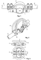
- Fig. 1 shows a conventional expansion connector with a blade design, in which the current between the terminals 1 of the expansion connector is carried by copper or aluminium blades 2, also called “shunt".
- each connection terminal 1 is connected to a rigid tubular conductor 4, hereinafter referred to as rigid busbar or simply tube.
- the blades 2 are normally bended and are relative flexible so as to allow a longitudinal displacement L of each connection terminal 1, for instance, caused by thermal expansion/contraction of the rigid busbar 4.
- the blades 2 are thin and a gap is kept between each of them in order to allow the longitudinal displacement of each tube 4.
- Expansion connectors with blade design are normally used in voltage applications up to 330 kV and are relatively cheap. However, since the sharp edges of the blades 2 may give rise to corona and radio interference phenomenon at higher voltages, these connectors cannot be used for voltage levels above 330 kV.
- expansion connectors with cable design are generally used in high voltage applications above 400 kV.
- This type of connectors is typically used at upper voltages because the absence of sharp edges in the cable connectors decreases the voltage gradient around the cables and therefore, corona phenomenon can only appear at voltage levels much higher than with conductors with sharp edges.
- Fig. 2 shows an example of conventional expansion connector with cable design, in which the current is transported between the terminals 5 of the expansion connector by flexible, cable conductors 6.
- the number and size of the cables 6 are defined by the current to be carried by the expansion connector.
- This type of expansion connectors has the disadvantage that it is not as compact as expansion connectors with blade design. Further, the flexible cables 6 are normally made of aluminium, which render the connector comparatively much more expensive.
- Expansion connectors designed with blades are less expensive but can only be used in 400 kV (and above) applications if the corona and Radio Interference Voltage acceptance criteria of the customer are not too high.
- An alternative consist in providing a corona ring for limiting and reducing the corona phenomenon, such as illustrated in Fig. 3 .
- Fig. 3 shows an expansion connector designed with a pair of blades 7 between the connector terminals 8 and protected by a corona ring 9.
- this solution is also quite expensive and not very compact. Further, supports for the corona ring 9 have to be provided.
- the present invention aims at overcoming the disadvantages and shortcomings of the prior art discussed above and an object thereof is to provide a corona shield device suitable for high voltage expansion connectors and which is cost-effective and of compact design.
- a further object of the present invention is to provide an expansion connector comprising the corona shield device of the present invention.
- a corona shield device for an expansion connector for high voltage applications comprising a shielding part adapted to cover a flexible conducting element of the expansion connector, wherein the shielding part as a smooth external surface adapted to decrease an electric potential gradient around the flexible conducting element to a value below a corona discharge threshold.
- the smooth external surface of the shielding part avoids or reduces the formation of strong potential gradients around sharp edges of the flexible conducting element, thereby, avoiding or limiting corona and radio interference effects.
- the corona shield device further comprises a flexible attachment element (or more) adapted to flexibly attach the shielding part to an attachment point of the expansion connector.
- the shielding part can be flexibly moved with respect to the attachment point and therefore, reversibly follow the expansion or contraction of the expansion connector while effectively protecting the flexible conducting element against corona effects.
- the present invention also provides an expansion connector for high voltage applications, comprising: a first connection part adapted to connect to a first element; a second connection part adapted to connect to a second element that is movable with respect to the first element; a flexible conducting element adapted to flexibly couple the first and second connection parts along an axial direction; and a corona shield device according to the invention.
- the shielding part is flexibly attached to respective attachment points of the first and second connection parts by flexible attachment elements.
- the present invention provides at least two major advantages over conventional high voltage connectors.
- the cost of this solution is cheaper than the cost of expansion connectors of aluminium cable design.
- the expansion connector of the present invention has a more compact design so that it can be used on High Voltage DC applications where phase-to-ground distances are reduced.
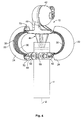
- Fig. 4 shows an expansion connector device 10 of blade design and having a corona shield device 20 according to an embodiment of the present invention.
- the expansion connector 10 has two flexible conducting elements (at least one), which are preferably provided as a pair of symmetrical shunt elements 30 or blades.
- the corona shield device 20 is provided to cover each of the shunt elements 30 and protect the expansion connector 10 from corona discharge effects that could occur due to the formation of significant potential gradients around and along one or more of the sharp edges 35 of the shunts 30 at high operating voltages.
- Each shunt 30 is electrically and mechanically coupled to two different parts of the expansion connector 10, a connector body 40 and a fastening element 50, which are respectively adapted to be connected to different equipments.
- the connector body 40 may have an articulated part 42 adapted to be fixed to a terminal of an equipment such as a thyristor valve (not shown) and to allow the direction of the connector body axis Z to be varied with respect to the equipment terminal by a certain angle.
- the articulated part 42 may be rigidly fixed to the equipment terminal using bolts.
- the fastening element 50 is opposed to the connector body 40 and is disposed along the axial direction Z of the connector body 40.
- the fastening element 50 provides the mechanical and electrical coupling to another equipment or equipment terminal, such as a rigid tubular conductor or busbar 4.
- the fastening element 50 is formed by a pair of keepers 52 that are adjusted around the cross-section of the tubular conductor 4 within a distance from the end of the tubular conductor 4.
- the keepers 52 may be fixed to the tube 4 by joining their end parts with one or more bolts 55.
- the connector body 40 may further comprise an elongated portion 44 opposed to the articulated part 42 along the axial direction Z.
- the elongated portion 44 is adapted to pass through the open end of the tubular busbar 4, at least partially, and to slide within the tubular busbar 4 in order to guide the busbar 4 during displacements along the axial direction Z caused by thermal expansions and to maintain the keepers 52 concentrically aligned with the connector body 40. This also improves the mechanic stability of the expansion connector 10 against rotations.
- the shunts 30 are arranged on a plane parallel to the connector axis Z and are symmetrically disposed in relation to one another around this axis. Each shunt 30 is electrically coupled to the connector body 40 and the fastening element 50.
- the shunt blades are bended along a length followed by the transport current when a voltage is applied between the shunt connections 40 and 50, which allow the shunt connections 40 and 50 to move with respect to each other during expansion/contraction of the expansion connector 10.
- the length and cross-section of the shunts 30 are determined based on the current and voltage application of the expansion connector 10 and the required flexibility for allowing a desired degree of bending of the shunts 30.
- the shunts 30 are made of an electrical conducting material such as a metal like aluminium or copper.
- any other electrical conducting material suitable for sustaining high voltages across the shunt 30 and having the required flexibility may be used.
- the corona shield device 20 is designed so as to surround at least one or more of the sharp edges of the flexible conducting element.
- the expansion corona shield device 20 comprises two symmetric shielding parts 22 adapted to cover the pair of shunts 30 and to offer an external smooth surface of the expansion connector 10.
- Each shunt element 30 has an electrical cross-section (in the direction transverse to the transport current) with a substantially rectangular shape that defines four sharp edges along the length of the shunt element 30.
- the shielding part 22 is then designed so as to cover at least the sharp edges 35 that run along the outward external surface of the shunt 30 and with a smooth external surface 24 in order to prevent the development of significant potential gradients around these edges 35 during operation at the desired range of voltages.
- the dimensions and form of the shielding part 22 depend on the particular form and size of the flexible conducting element of the expansion connector 10.
- the inner surface of the shielding part 22 (i.e. the surface facing the shunt 30) is adapted to involve the shunt 30 or at least the outward sharp edges 35 along the transport current path, entirely or at least over a significant portion of the shunt length.
- This inner surface may be in contact or be brought in contact with the shunt 30 during the expansion/compression of the expansion connector 10.
- the expansion corona shield 20 may be designed so that direct physical contact between the shielding part 22 and the shunt element 30 is avoided during expansion/compression of the expansion connector 10.
- the shielding part 22 is formed from a metal sheet or foil having a suitable thickness for providing the desired shielding effect and/or the desired degree of rigidity.
- the shielding part 22 is designed so as to have a smooth external surface 24 of a regular shape without sharp edges and with a limited surface roughness.
- the external surface 24 may have an average roughness, also called profile roughness parameter Ra, close to 1.25 ⁇ m or below.
- the shielding part 22 may be provided as foil with a concave or curved shape adapted to surround entirely or at least a significant portion of the shunt 30 along the transport current path.
- the shape of the shielding part 22 substantially follows the curvature of the underlying shunt element 30.
- the curvature of the external surface 24 of the shielding part 22 along the transport current path of the shunt element 30 is characterized by a radius of curvature R1.
- the radius R1 defines the curvature of the shielding part 22 in a longitudinal plane that is parallel to the axial direction Z of the expansion connector 10, and is selected depending on the size and own curvature of the shunt 30.
- the length of the shielding part 22 depends on the desired coverage of the shunt 30.
- the external surface 24 is also designed with a smooth, curved shape along the width of the shielding part 22 that is on a cross-sectional plane that bisects the shielding part 22 along the radius R1.
- the width of the shielding part 22 depends on the desired degree of coverage of the shunt cross-section. Preferably, it should be sufficient for substantially covering the outward sharp edges 35 of the shunt 30.
- the external surface 24 of the shielding part 22 has two lateral sides 26 that are substantially parallel to each other and which cover the lateral sides 38 of the shunt 30 (or at least partially).
- the two lateral sides 26 are joined by two rounded edges 28 which are separated by a certain distance d along the shield width. This distance depends on the dimensions of the shunt cross-section itself.
- Each rounded edge 28 is opposed to the respective sharp edge 35 at the outward surface of the shunt 30 and continuously run substantially parallel to the sharp edge 35 along a selected length of the shielding part 22.
- the cross-section width, and curvature R2 of the Shielding part 22 is selected based on the lateral dimensions of the shunt cross-section, the degree of sharpness of the shunt edges 35, which in the present case is simply defined as the angle formed by the adjacent walls defining the sharp edge, the voltage level of the application as well as design considerations for providing a compact shield.
- each rounded edge 28 is a critical parameter since they surround the sharpest regions of the shunt element 30.
- the radius R2 must be selected so as to ensure that the potential gradients formed around the respective sharp edge 35 are maintained below the corona discharge threshold at the desired range of operating voltages.
- each rounded edge 28 has a similar external radius of curvature R2 since the shunt 30 has a symmetrical shape with sharp edges 35 of similar sharpness.
- an external surface with rounded edges of different curvature may be provided, for instance, for covering a shunt element with an asymmetrical cross-section and/or comprising edges of different sharpness.
- the design of the external surface 24 described above allows providing a corona shield device 20 with a compact size that fits around each shunt 30 of the expansion connector 10 without occupying much volume.
- a shielding part with other shapes of external surface as long as it is smooth enough and substantially covers the shunt edges.
- an external surface with a substantially semi-circular curvature along the width of shield, that is, with no rounded edges 28 and parallel lateral sides 26, and wide enough for covering both sharp edges 35 might be provided.
- the external radius R1 and/or edge radius R2 are defined in accordance with the voltage level of the particular application, the shape and dimensions of the shunt element 30 itself so as to provide a smooth external surface with a regular shape suitable for reducing the potential gradient around the shunt element 30 to a value below the corona discharge threshold. This means that the required degree of smoothness and/or regularity of the shield increases with the increase of the operation voltage level.
- the corona discharge threshold or electric potential gradient limit for inception of the corona discharge depends on several factors. For accessories of High Voltage substations, the gradient limit is typically below 20 kV/cm, more specifically, between 13 and 16 kV/cm. However, the corona discharge threshold may vary based on the roughness of the fittings, the atmospheric pressure, the temperature, the humidity of air.
- a corona shield device may also be conveniently designed for protecting a flat conducting element with sharp edges.
- the external surface of the shielding part may be designed with no curvature along the length of the flexible conducting element and with a curved shape along its width for enveloping the sharp edges of the flexible conducting element and protecting them against corona.
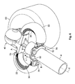
- the shielding parts 22 of the corona shield device 20 are fixed on different parts of the expansion connector 10, a first attachment point A provided on the connector body (40) and a second attachment point B provided on the fastening element 50.
- the shielding part 22 is preferably made of an alloy, such as aluminium alloy, in order to ensure electrical continuity of the electric potential while providing at the same time mechanical rigidity to its component parts.
- the shielding part 22 may be fixed to the attachments points A and B by welding, which contributes to increase the effective electrical cross section of the connector for the purpose of carrying current.
- the shielding part 22 thus provides both mechanical and corona protection to the expansion connector 10.
- the mechanical rigidity of the shield 22 would not allow it to adapt to the compression/expansion of the shunt 30.
- the keepers 52 and the connector body 40 are respectively fixed to the tubular busbar 4 and to the equipment terminal 60.
- the keepers 52 rigidly fixed to the tube 4 move along the axial direction Z by a same displacement L while the connector body 40 remains fixed to the equipment terminal 60.
- the expansion connector 10 is compressed into a compression state.
- the keepers 52 are moved away from the connector body 40 by a similar amount, forcing the expansion connector 10 to extend into a state of expansion.
- the corona shield device 20 may be provided with flexible attachment elements for flexibly attaching the shielding part 22 to the expansion connector 10.
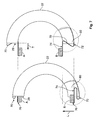
- Fig. 7 schematically illustrates an expansion corona shield with flexible attachment elements 70 according to an embodiment of the present invention.
- the details of the expansion connector shown in Fig. 6 are omitted in Fig. 7 .
- the image on the left-hand side shows a state of expansion, in which the attachment points A and B are separated by a given distance.
- the image on the right-hand side illustrates a state of compression in which the attachment points A and B are approached to each other by an amount L.
- Each half of the expansion corona shield 20 comprises flexible attachment elements (at least one at each end of the shielding part 22) for attaching the shielding part 22 to the attachment portions A and B which are provided for this purpose on the connector body 40 and the keepers 52, respectively.
- the flexible attachment elements may be made of an electrical conducting material, such as a metal, so as to carry current during expansion/compression of the connector 10 too.
- the flexible attachment element may be provided by a strap 70 designed with a special Z-shape.
- the Z-shape is obtained by bending the strap 70 at two different points along its length and in different directions.
- a first extremity 72 of the strap 70 is coupled to the external surface 24 of the shielding part 22 and extends from a border 29 of the shielding part 22, preferably, from an intermediate position along the border 29.
- a second extremity 74 opposed to the first extremity 72 serves as attaching extremity for connecting the strap 70 to attachment portions A or B of the expansion connector 10.
- the second extremity 74 may be provided with a flange 76 or hook for snatching to a suitable cavity provided in the attachment portions A or B.
- the strap 70 is preferably made from the same metal sheet of the shielding part 22 but could also be provided as a separate part that is fixed to the border 29.
- the two extremities of the strap 70 are preferably substantially flat and parallel to each other.
- the Z-shape provides elastic properties to the strap 70 in the direction perpendicular to the flat extremities 72, 74 and allows the strap 70 to compress or expand in this direction when a force is applied to any of the extremities.
- a first strap 70 is provided for fixing the shielding part 22 to attachment portion A, which is provided on the connector body 40 and, therefore, represents a fixed attachment point of the shielding part 22 during expansion/contraction of the expansion connector 10 when the connector body 40 is coupled to the equipment terminal 60.
- a second strap 70 is fixed to attachment portion B, which is provided on the movable keeper 52 and therefore, represents a movable, attachment point of the shielding part 22.
- both straps 70 are substantially bended so that the attaching extremity 74 and the respective attachments points A (or B) are approximately at an intermediate distance from the top (or bottom) of the border 29 of the shielding part 22.
- the shielding part 22 substantially covers the shunt 30 (not shown) and is disposed in a symmetrical manner around the shunt 30.
- the attachment portion B follows the tube expansion by the same amplitude and approaches the fixed attachment portion A.
- the attaching extremity 74 is also forced to move, causing the Z-shape of the strap 70 to extend or stretch in the displacement direction by a given amplitude.
- the stretch of the strap 70 causes the shielding part 22 to be displaced in the same direction although by a different amount that depends on the amplitude L and the flexibility of strap 70.
- the displacement of the shielding part 22 causes the strap 70 at the opposed side of the shield 22 to stretch with respect to the fixed attachment portion A, increasing the distance between the first and second extremities parts 72, 74 by a given amount that depends on the flexibility of the strap 70.
- the shielding part 22 can be freely moved in the longitudinal direction Z.
- the attachment portion B follows the contraction of the busbar, increasing its distance from the fixed attachment portion A by the same amount.
- the pair of straps 70 has similar elastic properties. Therefore, they are stretched or compressed by substantially a same amount U2 when the distance between attachment points A and B decreases or increases, respectively, by an amount L.
- the stretching amplitude of each strap may be different.
- the compression of the shunt 30 in the longitudinal direction also results in the shape of the shunt 30 being elongated in the direction transverse to the longitudinal displacement L. If the elongation is too important and/or the shielding part 22 is provided very close to shunt, the elongation may be blocked by the shielding part 22 or damage it.
- the flexible attachment elements may be designed so as to allow a relative displacement of the shielding part 22 in the direction transverse to the longitudinal displacement of points A and B.
- the special Z-shape of the straps 70 allow the shielding part 22 to follow both the longitudinal displacement of attachment portion B and the elongation of the shunt 30 in the transverse direction. At the same time, the strap 70 provides sufficient rigidity for maintaining the shielding part 22 aligned with the shunt 30.
- the size of the strap 70 may be selected so as to allow the shield 22 to fully follow the maximum amplitude of expansion/contraction of the connector 10 under operating conditions.
- the length of the attaching extremity 74 may be also selected so as to a reserve a minimum distance between the border 29 of the shielding part 22 and the attachment portions A (or B) at all times.
- the maximum elongation of the shunt 30 expected during expansion/contraction of the connector may also be taken into account.
- the present invention thus make possible to provide a corona shield device that can adjust to the effects of expansion of the connector 10 in two orthogonal directions while providing corona protection at all times.
- the working principle of the expansion corona shield according to the present invention depends on the displacement of the attachment portions A and B with respect to each other, irrespective from which attachment portion A or B of the connector is fixed or moved.
- the expansion corona shield described above may be also applied to expansion connectors in which both attachment portions A and B are movable such as expansions connectors adapted to interconnect two rigid busbars.
- the shielding part may be provided with only one flexible attachment element 70, for instance at the side of the shielding part to be attached to the movable part of the expansion connector, while the opposed side of the shielding part is rigidly attached to the fixed part of the expansion connector.
- the expansion corona shield of the invention may be conveniently used in applications where high currents are transported by conductors with irregular edges, irrespective from the conductors being flexible or not.
Landscapes
- Connector Housings Or Holding Contact Members (AREA)
Abstract
Description
- The present invention relates to expansion connectors for electrically interconnecting equipments in high voltage applications, and more particularly, to corona shielding of expansion connectors for voltage levels above 400 kV.
- Corona phenomenon is a luminous partial discharge from conductors and insulators due to ionization of air which occurs when the electrical field, that is, the electric potential gradient exceeds a critical value, a corona discharge threshold.
- Corona may cause several damage and environmental disturbing effects, in particular with regard to power transmission equipment and installations.
- For instance, corona discharge around conductors may generate corrosive materials, such as ozone and nitrogen oxides, which yield nitric acid under conditions of high humidity. These corrosive materials shorten the life span of high voltage lines and substations components. Corona processes may also cause damage to High voltage (HV) insulators, especially non-ceramic (NCI) insulators.
- Corona also generates audio noise and/or Radio Interference (RI/RFI) mainly to AM transmissions, which may raise customer complaints.
- Corona effects are particularly important around conductors submitted to high tensions and exhibiting sharps points or edges at the conductor surface. The potential gradients become particularly large around sharp edges, which significantly reduce the critical voltage above which a corona discharge occurs with respect to a conductor having a regular surface.
- Therefore, power transmission devices and equipments for high voltage applications require protection against corona discharge effects.
- High voltage installations such as switchyards commonly use flexible conductors and rigid tubular conductors for electrically interconnecting equipments such as transformers, disconnectors, circuit breakers or other electrical or power electrical device used in AC substations and DC converters.
- Rigid tubular conductors offer several advantages over flexible conductors. For instance, they can be provided with large size and cross section for carrying high currents (i.e.: 4000 - 6000 Amps). Their mechanical rigidity also allows reducing electro-dynamic movements of the tube during short circuits in the switchyard.
- However, rigid tubular conductors are responsive to variations of temperature caused by atmospheric conditions or the heat generated by the currents transported by the conductor, which may lead to a dilatation (or contraction) of the tube due to thermal expansion, namely, along the axial direction of the tube.
- Rigid tubular conductors are then usually connected to other equipment, such as a thyristor valve or another rigid busbar, using expansion connectors.
- An expansion connector transfers the electrical current received from one connected terminal, such as a busbar, to another equipment terminal, such as terminal connection of a thyristor valve, while providing an expandable interconnection that allows relative displacements between the two connected parts such as those caused by thermal expansion.
-
Figs. 1 and 2 illustrate two types of expansion connectors that are conventionally used in high voltage applications for connecting rigid tubular conductors to other equipment. -
Fig. 1 shows a conventional expansion connector with a blade design, in which the current between theterminals 1 of the expansion connector is carried by copper oraluminium blades 2, also called "shunt". In the illustrated example, eachconnection terminal 1 is connected to a rigidtubular conductor 4, hereinafter referred to as rigid busbar or simply tube. - The
blades 2 are normally bended and are relative flexible so as to allow a longitudinal displacement L of eachconnection terminal 1, for instance, caused by thermal expansion/contraction of therigid busbar 4. Theblades 2 are thin and a gap is kept between each of them in order to allow the longitudinal displacement of eachtube 4. - Expansion connectors with blade design are normally used in voltage applications up to 330 kV and are relatively cheap. However, since the sharp edges of the
blades 2 may give rise to corona and radio interference phenomenon at higher voltages, these connectors cannot be used for voltage levels above 330 kV. - For this reason, expansion connectors with cable design are generally used in high voltage applications above 400 kV.
- This type of connectors is typically used at upper voltages because the absence of sharp edges in the cable connectors decreases the voltage gradient around the cables and therefore, corona phenomenon can only appear at voltage levels much higher than with conductors with sharp edges.
-
Fig. 2 shows an example of conventional expansion connector with cable design, in which the current is transported between theterminals 5 of the expansion connector by flexible,cable conductors 6. The number and size of thecables 6 are defined by the current to be carried by the expansion connector. - This type of expansion connectors has the disadvantage that it is not as compact as expansion connectors with blade design. Further, the
flexible cables 6 are normally made of aluminium, which render the connector comparatively much more expensive. - Expansion connectors designed with blades are less expensive but can only be used in 400 kV (and above) applications if the corona and Radio Interference Voltage acceptance criteria of the customer are not too high.
- An alternative consist in providing a corona ring for limiting and reducing the corona phenomenon, such as illustrated in
Fig. 3 . -
Fig. 3 shows an expansion connector designed with a pair ofblades 7 between theconnector terminals 8 and protected by acorona ring 9. However, this solution is also quite expensive and not very compact. Further, supports for thecorona ring 9 have to be provided. - Consequently, there is a need for cost-effective and compact expansion connectors suitable for high voltage applications, namely, for voltage levels of 400 kV and above.
- The present invention aims at overcoming the disadvantages and shortcomings of the prior art discussed above and an object thereof is to provide a corona shield device suitable for high voltage expansion connectors and which is cost-effective and of compact design.
- A further object of the present invention is to provide an expansion connector comprising the corona shield device of the present invention.
- This object is solved by the subject matter of the independent claims. Advantageous embodiments of the present invention are defined by the dependent claims.
- According to the present invention, it is provided a corona shield device for an expansion connector for high voltage applications, comprising a shielding part adapted to cover a flexible conducting element of the expansion connector, wherein the shielding part as a smooth external surface adapted to decrease an electric potential gradient around the flexible conducting element to a value below a corona discharge threshold.
- The smooth external surface of the shielding part avoids or reduces the formation of strong potential gradients around sharp edges of the flexible conducting element, thereby, avoiding or limiting corona and radio interference effects.
- According to an advantageous development of the invention, the corona shield device further comprises a flexible attachment element (or more) adapted to flexibly attach the shielding part to an attachment point of the expansion connector.
- In this way, the shielding part can be flexibly moved with respect to the attachment point and therefore, reversibly follow the expansion or contraction of the expansion connector while effectively protecting the flexible conducting element against corona effects.
- The present invention also provides an expansion connector for high voltage applications, comprising: a first connection part adapted to connect to a first element; a second connection part adapted to connect to a second element that is movable with respect to the first element; a flexible conducting element adapted to flexibly couple the first and second connection parts along an axial direction; and a corona shield device according to the invention.
- In a further embodiment, the shielding part is flexibly attached to respective attachment points of the first and second connection parts by flexible attachment elements.
- Thus, by combining a corona shield device with the use of shunts on high voltage connectors, the present invention provides at least two major advantages over conventional high voltage connectors. First, the cost of this solution is cheaper than the cost of expansion connectors of aluminium cable design. Second, the expansion connector of the present invention has a more compact design so that it can be used on High Voltage DC applications where phase-to-ground distances are reduced.
- The accompanying drawings are incorporated into and form a part of the specification for the purpose of explaining the principles of the invention. The drawings are not to be construed as limiting the invention to only the illustrated and described examples of how the invention can be made and used.
- Further features and advantages will become apparent from the following and more detailed description of the invention as illustrated in the accompanying drawings, in which:
-
Fig. 1 is a perspective view of a conventional expansion connector having a blade design; -
Fig. 2 is a perspective view of a conventional expansion connector having cable design; -
Fig. 3 schematically illustrates an expansion connector with a pair of blades and a corona ring when viewed from the side (upper image) and from the top of the corona ring (lower image); -
Fig. 4 schematically illustrates a perspective view of an expansion connector connected to a busbar and having an expansion corona shield according to an embodiment of the present invention; -
Fig. 5 schematically illustrates a longitudinal view (upper image) of the expansion connector and expansion corona shield shown inFig. 4 , and a bottom view (lower image) along the longitudinal axis Z and from the side of the busbar; -
Fig. 6 schematically illustrates a perspective view of the expansion connector and expansion corona shield shown inFig. 4 when also connected to an equipment terminal; -
Fig. 7 schematically illustrates a half of an expansion corona shield with flexible attachment elements according to an embodiment of the present invention, for a given distance between attachment points A and B of the shield (left-hand image) and when the distance between the attachment points decrease (right-hand image). The regions encircled by a dashed line represent a partial cut-way view of the shield. - Advantageous embodiments of a corona shield device constituted according to the invention will now be described in further detail with reference to the accompanying drawings.
-
Fig. 4 shows anexpansion connector device 10 of blade design and having a corona shield device 20 according to an embodiment of the present invention. - The
expansion connector 10 has two flexible conducting elements (at least one), which are preferably provided as a pair ofsymmetrical shunt elements 30 or blades. - The corona shield device 20 is provided to cover each of the
shunt elements 30 and protect theexpansion connector 10 from corona discharge effects that could occur due to the formation of significant potential gradients around and along one or more of thesharp edges 35 of theshunts 30 at high operating voltages. - Each
shunt 30 is electrically and mechanically coupled to two different parts of theexpansion connector 10, aconnector body 40 and afastening element 50, which are respectively adapted to be connected to different equipments. - The
connector body 40 may have an articulatedpart 42 adapted to be fixed to a terminal of an equipment such as a thyristor valve (not shown) and to allow the direction of the connector body axis Z to be varied with respect to the equipment terminal by a certain angle. The articulatedpart 42 may be rigidly fixed to the equipment terminal using bolts. - The
fastening element 50 is opposed to theconnector body 40 and is disposed along the axial direction Z of theconnector body 40. Thefastening element 50 provides the mechanical and electrical coupling to another equipment or equipment terminal, such as a rigid tubular conductor orbusbar 4. - In
Fig. 4 , thefastening element 50 is formed by a pair ofkeepers 52 that are adjusted around the cross-section of thetubular conductor 4 within a distance from the end of thetubular conductor 4. Thekeepers 52 may be fixed to thetube 4 by joining their end parts with one ormore bolts 55. - The
connector body 40 may further comprise anelongated portion 44 opposed to the articulatedpart 42 along the axial direction Z. Theelongated portion 44 is adapted to pass through the open end of thetubular busbar 4, at least partially, and to slide within thetubular busbar 4 in order to guide thebusbar 4 during displacements along the axial direction Z caused by thermal expansions and to maintain thekeepers 52 concentrically aligned with theconnector body 40. This also improves the mechanic stability of theexpansion connector 10 against rotations. - The
shunts 30 are arranged on a plane parallel to the connector axis Z and are symmetrically disposed in relation to one another around this axis. Eachshunt 30 is electrically coupled to theconnector body 40 and thefastening element 50. The shunt blades are bended along a length followed by the transport current when a voltage is applied between theshunt connections shunt connections expansion connector 10. - The length and cross-section of the
shunts 30 are determined based on the current and voltage application of theexpansion connector 10 and the required flexibility for allowing a desired degree of bending of theshunts 30. Preferably, theshunts 30 are made of an electrical conducting material such as a metal like aluminium or copper. However, any other electrical conducting material suitable for sustaining high voltages across theshunt 30 and having the required flexibility may be used. - The corona shield device 20 is designed so as to surround at least one or more of the sharp edges of the flexible conducting element.
- In the embodiment shown in
Fig. 4 , the expansion corona shield device 20 comprises twosymmetric shielding parts 22 adapted to cover the pair ofshunts 30 and to offer an external smooth surface of theexpansion connector 10. - Each
shunt element 30 has an electrical cross-section (in the direction transverse to the transport current) with a substantially rectangular shape that defines four sharp edges along the length of theshunt element 30. - The shielding
part 22 is then designed so as to cover at least thesharp edges 35 that run along the outward external surface of theshunt 30 and with a smoothexternal surface 24 in order to prevent the development of significant potential gradients around theseedges 35 during operation at the desired range of voltages. - The dimensions and form of the shielding
part 22 depend on the particular form and size of the flexible conducting element of theexpansion connector 10. - The inner surface of the shielding part 22 (i.e. the surface facing the shunt 30) is adapted to involve the
shunt 30 or at least the outwardsharp edges 35 along the transport current path, entirely or at least over a significant portion of the shunt length. This inner surface may be in contact or be brought in contact with theshunt 30 during the expansion/compression of theexpansion connector 10. Alternatively, the expansion corona shield 20 may be designed so that direct physical contact between the shieldingpart 22 and theshunt element 30 is avoided during expansion/compression of theexpansion connector 10. - Preferably, the shielding
part 22 is formed from a metal sheet or foil having a suitable thickness for providing the desired shielding effect and/or the desired degree of rigidity. - The shielding
part 22 is designed so as to have a smoothexternal surface 24 of a regular shape without sharp edges and with a limited surface roughness. In order to have a full efficiency of the corona shield device 20, theexternal surface 24 may have an average roughness, also called profile roughness parameter Ra, close to 1.25 µm or below. - In the case of a
shunt 30 having a substantially semi-circular shape such as illustrated inFig. 4 , the shieldingpart 22 may be provided as foil with a concave or curved shape adapted to surround entirely or at least a significant portion of theshunt 30 along the transport current path. Preferably, the shape of the shieldingpart 22 substantially follows the curvature of theunderlying shunt element 30. - As shown in
Fig. 4 , the curvature of theexternal surface 24 of the shieldingpart 22 along the transport current path of theshunt element 30 is characterized by a radius of curvature R1. The radius R1 defines the curvature of the shieldingpart 22 in a longitudinal plane that is parallel to the axial direction Z of theexpansion connector 10, and is selected depending on the size and own curvature of theshunt 30. The length of the shieldingpart 22 depends on the desired coverage of theshunt 30. - The
external surface 24 is also designed with a smooth, curved shape along the width of the shieldingpart 22 that is on a cross-sectional plane that bisects the shieldingpart 22 along the radius R1. The width of the shieldingpart 22 depends on the desired degree of coverage of the shunt cross-section. Preferably, it should be sufficient for substantially covering the outwardsharp edges 35 of theshunt 30. - As shown in the lower image of
Fig. 5 , theexternal surface 24 of the shieldingpart 22 has twolateral sides 26 that are substantially parallel to each other and which cover the lateral sides 38 of the shunt 30 (or at least partially). The twolateral sides 26 are joined by tworounded edges 28 which are separated by a certain distance d along the shield width. This distance depends on the dimensions of the shunt cross-section itself. - Each
rounded edge 28 is opposed to the respectivesharp edge 35 at the outward surface of theshunt 30 and continuously run substantially parallel to thesharp edge 35 along a selected length of the shieldingpart 22. - The cross-section width, and curvature R2 of the
Shielding part 22 is selected based on the lateral dimensions of the shunt cross-section, the degree of sharpness of the shunt edges 35, which in the present case is simply defined as the angle formed by the adjacent walls defining the sharp edge, the voltage level of the application as well as design considerations for providing a compact shield. - The radius of curvature R2 of each
rounded edge 28 is a critical parameter since they surround the sharpest regions of theshunt element 30. The radius R2 must be selected so as to ensure that the potential gradients formed around the respectivesharp edge 35 are maintained below the corona discharge threshold at the desired range of operating voltages. - In
Fig. 5 , eachrounded edge 28 has a similar external radius of curvature R2 since theshunt 30 has a symmetrical shape withsharp edges 35 of similar sharpness. However, an external surface with rounded edges of different curvature may be provided, for instance, for covering a shunt element with an asymmetrical cross-section and/or comprising edges of different sharpness. - The design of the
external surface 24 described above allows providing a corona shield device 20 with a compact size that fits around eachshunt 30 of theexpansion connector 10 without occupying much volume. However, it might be envisaged to provide a shielding part with other shapes of external surface as long as it is smooth enough and substantially covers the shunt edges. For instance, an external surface with a substantially semi-circular curvature along the width of shield, that is, with norounded edges 28 and parallellateral sides 26, and wide enough for covering bothsharp edges 35 might be provided. - The external radius R1 and/or edge radius R2 are defined in accordance with the voltage level of the particular application, the shape and dimensions of the
shunt element 30 itself so as to provide a smooth external surface with a regular shape suitable for reducing the potential gradient around theshunt element 30 to a value below the corona discharge threshold. This means that the required degree of smoothness and/or regularity of the shield increases with the increase of the operation voltage level. - The corona discharge threshold or electric potential gradient limit for inception of the corona discharge depends on several factors. For accessories of High Voltage substations, the gradient limit is typically below 20 kV/cm, more specifically, between 13 and 16 kV/cm. However, the corona discharge threshold may vary based on the roughness of the fittings, the atmospheric pressure, the temperature, the humidity of air.
- A corona shield device according to the principles of the present invention may also be conveniently designed for protecting a flat conducting element with sharp edges. In this case, the external surface of the shielding part may be designed with no curvature along the length of the flexible conducting element and with a curved shape along its width for enveloping the sharp edges of the flexible conducting element and protecting them against corona.
- As shown in
Fig. 6 , the shieldingparts 22 of the corona shield device 20 are fixed on different parts of theexpansion connector 10, a first attachment point A provided on the connector body (40) and a second attachment point B provided on thefastening element 50. - The shielding
part 22 is preferably made of an alloy, such as aluminium alloy, in order to ensure electrical continuity of the electric potential while providing at the same time mechanical rigidity to its component parts. In this case, the shieldingpart 22 may be fixed to the attachments points A and B by welding, which contributes to increase the effective electrical cross section of the connector for the purpose of carrying current. The shieldingpart 22 thus provides both mechanical and corona protection to theexpansion connector 10. - However, in case the
shield 22 would be rigidly attached to theshunt 30, the mechanical rigidity of theshield 22 would not allow it to adapt to the compression/expansion of theshunt 30. - As shown in
Fig. 6 , thekeepers 52 and theconnector body 40 are respectively fixed to thetubular busbar 4 and to theequipment terminal 60. Thus, during thermal expansion of thetube 4 by a length L, thekeepers 52 rigidly fixed to thetube 4 move along the axial direction Z by a same displacement L while theconnector body 40 remains fixed to theequipment terminal 60. As a consequence, theexpansion connector 10 is compressed into a compression state. Similarly, in case the busbar length contracts by a given amount due to cooling, thekeepers 52 are moved away from theconnector body 40 by a similar amount, forcing theexpansion connector 10 to extend into a state of expansion. - In order to allow the shielding
part 22 to adjust to the expansion/contraction of theexpansion connector 10, the corona shield device 20 may be provided with flexible attachment elements for flexibly attaching the shieldingpart 22 to theexpansion connector 10. -
Fig. 7 schematically illustrates an expansion corona shield withflexible attachment elements 70 according to an embodiment of the present invention. For simplicity, the details of the expansion connector shown inFig. 6 are omitted inFig. 7 . - The image on the left-hand side shows a state of expansion, in which the attachment points A and B are separated by a given distance. The image on the right-hand side illustrates a state of compression in which the attachment points A and B are approached to each other by an amount L.
- Each half of the expansion corona shield 20 comprises flexible attachment elements (at least one at each end of the shielding part 22) for attaching the shielding
part 22 to the attachment portions A and B which are provided for this purpose on theconnector body 40 and thekeepers 52, respectively. - The flexible attachment elements may be made of an electrical conducting material, such as a metal, so as to carry current during expansion/compression of the
connector 10 too. - The flexible attachment element may be provided by a
strap 70 designed with a special Z-shape. The Z-shape is obtained by bending thestrap 70 at two different points along its length and in different directions. - A
first extremity 72 of thestrap 70 is coupled to theexternal surface 24 of the shieldingpart 22 and extends from aborder 29 of the shieldingpart 22, preferably, from an intermediate position along theborder 29. Asecond extremity 74 opposed to thefirst extremity 72 serves as attaching extremity for connecting thestrap 70 to attachment portions A or B of theexpansion connector 10. Thesecond extremity 74 may be provided with aflange 76 or hook for snatching to a suitable cavity provided in the attachment portions A or B. - The
strap 70 is preferably made from the same metal sheet of the shieldingpart 22 but could also be provided as a separate part that is fixed to theborder 29. - The two extremities of the
strap 70 are preferably substantially flat and parallel to each other. The Z-shape provides elastic properties to thestrap 70 in the direction perpendicular to theflat extremities strap 70 to compress or expand in this direction when a force is applied to any of the extremities. - As schematically represented in
Fig. 7 , afirst strap 70 is provided for fixing the shieldingpart 22 to attachment portion A, which is provided on theconnector body 40 and, therefore, represents a fixed attachment point of the shieldingpart 22 during expansion/contraction of theexpansion connector 10 when theconnector body 40 is coupled to theequipment terminal 60. - A
second strap 70 is fixed to attachment portion B, which is provided on themovable keeper 52 and therefore, represents a movable, attachment point of the shieldingpart 22. - In an initial state where the thermal expansion effects of the
busbar 4 are negligible, bothstraps 70 are substantially bended so that the attachingextremity 74 and the respective attachments points A (or B) are approximately at an intermediate distance from the top (or bottom) of theborder 29 of the shieldingpart 22. In this configuration, the shieldingpart 22 substantially covers the shunt 30 (not shown) and is disposed in a symmetrical manner around theshunt 30. - However, if the
busbar 4 expands by an amplitude L due to heating, the attachment portion B follows the tube expansion by the same amplitude and approaches the fixed attachment portion A. The attachingextremity 74 is also forced to move, causing the Z-shape of thestrap 70 to extend or stretch in the displacement direction by a given amplitude. - Since the shielding
part 22 is not rigidly connected to a fixed point, the stretch of thestrap 70 causes the shieldingpart 22 to be displaced in the same direction although by a different amount that depends on the amplitude L and the flexibility ofstrap 70. - At the same time, since the attachment portion A cannot move, the displacement of the shielding
part 22 causes thestrap 70 at the opposed side of theshield 22 to stretch with respect to the fixed attachment portion A, increasing the distance between the first andsecond extremities parts strap 70. Thus, the shieldingpart 22 can be freely moved in the longitudinal direction Z. - Similarly, if the
busbar 4 contracts by an amount L due to cooling, the attachment portion B follows the contraction of the busbar, increasing its distance from the fixed attachment portion A by the same amount. - In the present example, the pair of
straps 70 has similar elastic properties. Therefore, they are stretched or compressed by substantially a same amount U2 when the distance between attachment points A and B decreases or increases, respectively, by an amount L. However, in case thestraps 70 have different resilience, the stretching amplitude of each strap may be different. - The compression of the
shunt 30 in the longitudinal direction also results in the shape of theshunt 30 being elongated in the direction transverse to the longitudinal displacement L. If the elongation is too important and/or the shieldingpart 22 is provided very close to shunt, the elongation may be blocked by the shieldingpart 22 or damage it. - In order to prevent this situation, the flexible attachment elements may be designed so as to allow a relative displacement of the shielding
part 22 in the direction transverse to the longitudinal displacement of points A and B. - As shown in the partial cut-away view in
Fig. 7 , when thestrap 70 is compressed and expanded in the longitudinal direction L, the special Z-shape results in the attachingextremity 74 retracting to and expanding from thehollow space 80 surrounded by theborder 29 of the shieldingpart 22, respectively. - Thus, as shown in
Fig. 7 , when the attachment portions A and B approach to each other by an amount L, the attachingextremities 74 expand from theborder 29 by a certain amount T in the direction transverse to the longitudinal displacement L. This causes the shieldingpart 22 to move away from attachment portions A and B by the same amount in the opposite direction, and consequently, away from the connectedshunt 30. - If the distance between the attachment portions A and B is again increased due to thermal contraction of the
busbar 4, for instance, by returning to the expansion state illustrated in the left-hand side ofFig. 7 , the Z-shape of eachstrap 70 is compressed and each attachingextremity 74 partially retracts into thehollow space 80 with respect to theshield border 29. As a consequence, theshield 22 approaches again the attachment portions A and B in the transverse direction and therefore, theshunt 30 which meanwhile has also returned to its initial shape. - Consequently, the special Z-shape of the
straps 70 allow the shieldingpart 22 to follow both the longitudinal displacement of attachment portion B and the elongation of theshunt 30 in the transverse direction. At the same time, thestrap 70 provides sufficient rigidity for maintaining the shieldingpart 22 aligned with theshunt 30. - The size of the
strap 70 may be selected so as to allow theshield 22 to fully follow the maximum amplitude of expansion/contraction of theconnector 10 under operating conditions. - The length of the attaching
extremity 74 may be also selected so as to a reserve a minimum distance between theborder 29 of the shieldingpart 22 and the attachment portions A (or B) at all times. The maximum elongation of theshunt 30 expected during expansion/contraction of the connector may also be taken into account. - The present invention thus make possible to provide a corona shield device that can adjust to the effects of expansion of the
connector 10 in two orthogonal directions while providing corona protection at all times. - Although the present embodiment has been described with reference to the attachment portion A being fixed, those skilled in the art will immediately realize that the working principle of the expansion corona shield according to the present invention depends on the displacement of the attachment portions A and B with respect to each other, irrespective from which attachment portion A or B of the connector is fixed or moved. For instance, the expansion corona shield described above may be also applied to expansion connectors in which both attachment portions A and B are movable such as expansions connectors adapted to interconnect two rigid busbars.
- In addition, it may be envisaged to provide an expansion corona shield device in which the shielding part is fixed by a pair of straps of different elasticity. In another modification, the shielding part may be provided with only one
flexible attachment element 70, for instance at the side of the shielding part to be attached to the movable part of the expansion connector, while the opposed side of the shielding part is rigidly attached to the fixed part of the expansion connector. - Further, although the above embodiments were described in view of the application of the expansion corona shield to protect expansion connectors of blade design and intended for high voltage applications, other applications of the expansion corona shield may be readily envisaged by a person skilled in the art.
- In particular, the expansion corona shield of the invention may be conveniently used in applications where high currents are transported by conductors with irregular edges, irrespective from the conductors being flexible or not.
-
Reference sign Description Expansion connector of blade- type 1 Connection terminal 2 Blade or shunt 4 Rigid tubular conductor, busbar Expansion connector of cable- type 5 Connection terminal 6 Flexible cable Expansion connector of blade-type with corona ring 7 Blade 8 Connection terminal 9 Corona ring 10 Expansion connector device 20 Corona shield device 22 Shielding part 24 External surface 26 Lateral side 28 Rounded edge of external surface d Distance between rounded edges 29 End border of shielding part 30 flexible conducting element, shunt elements, blades 35 Sharp edges 38 Lateral side of shunt 40 connector body 42 articulated part 44 elongated portion 50 fastening element, 52 keepers 55 bolt 60 Equipment terminal 70 Flexible attachment element, strap 72 First extremity extending from border 74 Second extremity for attaching to connector, attaching extremity 76 flange 80 Hollow space surround by the end border L Longitudinal direction T Transverse direction z Axial direction of expansion connector A Fixed attachment point B Movable attachment point
Claims (15)
- A corona shield device for an expansion connector for high voltage applications, comprising:a shielding part (22) adapted to cover a flexible conducting element (30) of the expansion connector (10);wherein the shielding part (22) has a smooth external surface (24) adapted to decrease an electric potential gradient around the flexible conducting element (30) to a value that is below a corona discharge threshold.
- The corona shield device of claim 1, wherein the corona discharge threshold is below 20 kV/cm.
- The corona shield device of claim 1 or claim 2, wherein the external surface (24) has an average roughness Ra of substantially 1.25 µm or less.
- The corona shield device of any one of claims 1 to 3, wherein the shielding part (22) is adapted to surround at least a part of the flexible conducting element (30).
- The corona shield device of any one of claims 1 to 4, wherein the flexible conducting element (30) has a sharp edge (35), and
the shielding part (22) has an inner surface adapted to cover said sharp edge (35), said smooth external surface (24) having a rounded edge (28) opposed to said sharp edge (35). - The corona shield device of claim 5, wherein said rounded edge (28) has a radius of curvature (R2) that is selected based on a degree of sharpness of the sharp edge (35) and/or an intended operating voltage so as to reduce the electric potential gradient formed around the sharp edge (35) under operating voltage conditions.
- The corona shield device of any one of claims 1 to 6, wherein
the flexible conducting element (30) is a shunt element that is bended along a transport current path and has a sharp edge (35) along said transport current path, and
the shielding part (22) has a concave form with an external radius of curvature (R1) that is adapted to cover the sharp edge (35) along said transport current path. - The corona shield device of any one of claims 1 to 7, further comprising:a flexible attachment element (70) adapted to flexibly attach the shielding part (22) to an attachment point (A or B) of the expansion connector (10).
- The corona shield device of claim 8, wherein the flexible attachment element (70) is adapted to contract or expand along a longitudinal direction (L) so as to allow the shielding part (22) to move with respect to the attachment point (A or B) along said direction (L).
- The corona shield device of claim 8 or claim 9, wherein the flexible attachment element (70) is provided at a free border (29) of the shielding part (22) and has an attaching extremity (74) adapted to be fixed to said attachment point (A or B) of the expansion connector (10).
- The corona shield device of any one of claims 9 to 10, wherein the attaching extremity is adapted to extract from or retract to with respect to the free border (29) along a transverse direction (T) so as to allow the shielding part (22) to move with respect to the attachment point (A or B) along said direction.
- The corona shield device of any one of claims 8 to 11, wherein the flexible attachment element (70) is adapted to conduct electrical current from the shielding part (22) to the attachment point (A or B).
- An expansion connector device for high voltage application, comprising:a first connection part (40) adapted to connect to a first element (60);a second connection part (50) adapted to connect to a second element (4) that is movable with respect to the first element (60);a flexible conducting element (30) adapted to flexibly couple the first and second connection parts (40, 50) along an axial direction (Z); anda corona shield device (20) according to any one of claims 1 to 12.
- The expansion connector device of claim 13, wherein the shielding part (22) is flexibly attached to respective attachment points (A,B) of the first and second connection parts (40, 50) by at least one flexible attachment element (70).
- The expansion connector device of claim 14, wherein a first flexible attachment element (70) is attached to a fixed attachment point (A) provided on the connector body (40) and a second flexible attachment element (70) is attached to a movable attachment point (B) provided on the second connection part (52), which is movable with respect to the connector body (40).
Priority Applications (1)
| Application Number | Priority Date | Filing Date | Title |
|---|---|---|---|
| EP11290370.3A EP2557636B1 (en) | 2011-08-11 | 2011-08-11 | Corona shield for high voltage connectors |
Applications Claiming Priority (1)
| Application Number | Priority Date | Filing Date | Title |
|---|---|---|---|
| EP11290370.3A EP2557636B1 (en) | 2011-08-11 | 2011-08-11 | Corona shield for high voltage connectors |
Publications (2)
| Publication Number | Publication Date |
|---|---|
| EP2557636A1 true EP2557636A1 (en) | 2013-02-13 |
| EP2557636B1 EP2557636B1 (en) | 2016-11-16 |
Family
ID=44785750
Family Applications (1)
| Application Number | Title | Priority Date | Filing Date |
|---|---|---|---|
| EP11290370.3A Not-in-force EP2557636B1 (en) | 2011-08-11 | 2011-08-11 | Corona shield for high voltage connectors |
Country Status (1)
| Country | Link |
|---|---|
| EP (1) | EP2557636B1 (en) |
Cited By (5)
| Publication number | Priority date | Publication date | Assignee | Title |
|---|---|---|---|---|
| WO2014190906A1 (en) * | 2013-05-29 | 2014-12-04 | 国家电网公司 | High-voltage direct-current grounding switch and stationary contact component thereof |
| CN108539703A (en) * | 2018-04-18 | 2018-09-14 | 中国电力工程顾问集团西南电力设计院有限公司 | Double rotational structures between change of current change and converter valve applied to current conversion station |
| WO2021078354A1 (en) * | 2019-10-21 | 2021-04-29 | Abb Power Grids Switzerland Ag | Telescopic electric conductor and high voltage arrangement |
| US11017975B2 (en) * | 2016-08-24 | 2021-05-25 | Varian Medical Systems, Inc. | Electromagnetic interference containment for accelerator systems |
| GB2622045A (en) * | 2022-08-31 | 2024-03-06 | Eaton Intelligent Power Ltd | Branch busbar device |
Citations (4)
| Publication number | Priority date | Publication date | Assignee | Title |
|---|---|---|---|---|
| US1972616A (en) * | 1931-02-25 | 1934-09-04 | Ohio Brass Co | Electrostatic shield |
| US2789154A (en) * | 1952-05-29 | 1957-04-16 | Thomas F Peterson | Corona shielding |
| US3046327A (en) * | 1959-06-10 | 1962-07-24 | Ohio Brass Co | Corona ball |
| US3527875A (en) * | 1967-11-08 | 1970-09-08 | Anderson Electric Corp | High voltage bus connectors shielded against corona discharge |
-
2011
- 2011-08-11 EP EP11290370.3A patent/EP2557636B1/en not_active Not-in-force
Patent Citations (4)
| Publication number | Priority date | Publication date | Assignee | Title |
|---|---|---|---|---|
| US1972616A (en) * | 1931-02-25 | 1934-09-04 | Ohio Brass Co | Electrostatic shield |
| US2789154A (en) * | 1952-05-29 | 1957-04-16 | Thomas F Peterson | Corona shielding |
| US3046327A (en) * | 1959-06-10 | 1962-07-24 | Ohio Brass Co | Corona ball |
| US3527875A (en) * | 1967-11-08 | 1970-09-08 | Anderson Electric Corp | High voltage bus connectors shielded against corona discharge |
Cited By (8)
| Publication number | Priority date | Publication date | Assignee | Title |
|---|---|---|---|---|
| WO2014190906A1 (en) * | 2013-05-29 | 2014-12-04 | 国家电网公司 | High-voltage direct-current grounding switch and stationary contact component thereof |
| CN104252990A (en) * | 2013-05-29 | 2014-12-31 | 国家电网公司 | A HVDC grounding switch and a stationary contact component thereof |
| CN104252990B (en) * | 2013-05-29 | 2017-09-01 | 国家电网公司 | A kind of HVDC earthed switch and its static contact component |
| US11017975B2 (en) * | 2016-08-24 | 2021-05-25 | Varian Medical Systems, Inc. | Electromagnetic interference containment for accelerator systems |
| CN108539703A (en) * | 2018-04-18 | 2018-09-14 | 中国电力工程顾问集团西南电力设计院有限公司 | Double rotational structures between change of current change and converter valve applied to current conversion station |
| WO2021078354A1 (en) * | 2019-10-21 | 2021-04-29 | Abb Power Grids Switzerland Ag | Telescopic electric conductor and high voltage arrangement |
| US11664610B2 (en) | 2019-10-21 | 2023-05-30 | Hitachi Energy Switzerland Ag | Telescopic electric conductor and high voltage arrangement |
| GB2622045A (en) * | 2022-08-31 | 2024-03-06 | Eaton Intelligent Power Ltd | Branch busbar device |
Also Published As
| Publication number | Publication date |
|---|---|
| EP2557636B1 (en) | 2016-11-16 |
Similar Documents
| Publication | Publication Date | Title |
|---|---|---|
| US8258404B2 (en) | Insulation of busbars using insulating members having corrugated sections | |
| EP2557636B1 (en) | Corona shield for high voltage connectors | |
| KR101962506B1 (en) | High-capacity/efficiency transmission line design | |
| CN106953218B (en) | Power Busway Connectors with External Vise Brackets | |
| CN107017536B (en) | Adjustable Power Busway Connectors with Fork Busbars | |
| KR101846418B1 (en) | A protective electronic module for an hvdc convertor | |
| CN106961058A (en) | Electric power busway joint with length adjustment component | |
| EP1489692B1 (en) | Termination structure of cryogenic cable | |
| CN104040815A (en) | Connection structure for room temperature insulated superconducting cables | |
| US10651452B2 (en) | Connection assembly for a traction battery in particular for electric vehicles | |
| US8308508B2 (en) | Connector | |
| US11664610B2 (en) | Telescopic electric conductor and high voltage arrangement | |
| KR102755278B1 (en) | DIN Rail Shield | |
| US12348011B2 (en) | Sinusoidal tubular conducting busbar | |
| JP3744721B2 (en) | Flexible conductor and flexible connecting member | |
| CN210092388U (en) | Scalable generating line connecting device | |
| WO2022221996A1 (en) | Bus-duct and associated manufacturing method | |
| CN220107518U (en) | Spliced bus duct convenient to install | |
| US4517405A (en) | Compact conductor device | |
| CN223857896U (en) | Buckle type insulating protective sleeve for busbar | |
| CN222233309U (en) | An insulated flexible DC land cable | |
| JPH08126302A (en) | Power conversion device and manufacturing method thereof | |
| CN112243554A (en) | Conductor stops for busbars | |
| CN221328584U (en) | Connector for valve arrangement and HVDC converter comprising valve arrangement and such connector | |
| KR100773696B1 (en) | Ultra High Voltage Cable Protective Tube |
Legal Events
| Date | Code | Title | Description |
|---|---|---|---|
| PUAI | Public reference made under article 153(3) epc to a published international application that has entered the european phase |
Free format text: ORIGINAL CODE: 0009012 |
|
| AK | Designated contracting states |
Kind code of ref document: A1 Designated state(s): AL AT BE BG CH CY CZ DE DK EE ES FI FR GB GR HR HU IE IS IT LI LT LU LV MC MK MT NL NO PL PT RO RS SE SI SK SM TR |
|
| AX | Request for extension of the european patent |
Extension state: BA ME |
|
| 17P | Request for examination filed |
Effective date: 20130813 |
|
| RBV | Designated contracting states (corrected) |
Designated state(s): AL AT BE BG CH CY CZ DE DK EE ES FI FR GB GR HR HU IE IS IT LI LT LU LV MC MK MT NL NO PL PT RO RS SE SI SK SM TR |
|
| 17Q | First examination report despatched |
Effective date: 20160205 |
|
| GRAP | Despatch of communication of intention to grant a patent |
Free format text: ORIGINAL CODE: EPIDOSNIGR1 |
|
| INTG | Intention to grant announced |
Effective date: 20160601 |
|
| RIN1 | Information on inventor provided before grant (corrected) |
Inventor name: GODARD, JEROME Inventor name: ROYER, LAURENT |
|
| GRAS | Grant fee paid |
Free format text: ORIGINAL CODE: EPIDOSNIGR3 |
|
| GRAA | (expected) grant |
Free format text: ORIGINAL CODE: 0009210 |
|
| AK | Designated contracting states |
Kind code of ref document: B1 Designated state(s): AL AT BE BG CH CY CZ DE DK EE ES FI FR GB GR HR HU IE IS IT LI LT LU LV MC MK MT NL NO PL PT RO RS SE SI SK SM TR |
|
| REG | Reference to a national code |
Ref country code: GB Ref legal event code: FG4D |
|
| REG | Reference to a national code |
Ref country code: CH Ref legal event code: EP |
|
| REG | Reference to a national code |
Ref country code: IE Ref legal event code: FG4D |
|
| REG | Reference to a national code |
Ref country code: AT Ref legal event code: REF Ref document number: 846707 Country of ref document: AT Kind code of ref document: T Effective date: 20161215 |
|
| REG | Reference to a national code |
Ref country code: DE Ref legal event code: R096 Ref document number: 602011032405 Country of ref document: DE |
|
| PG25 | Lapsed in a contracting state [announced via postgrant information from national office to epo] |
Ref country code: LV Free format text: LAPSE BECAUSE OF FAILURE TO SUBMIT A TRANSLATION OF THE DESCRIPTION OR TO PAY THE FEE WITHIN THE PRESCRIBED TIME-LIMIT Effective date: 20161116 |
|
| REG | Reference to a national code |
Ref country code: NL Ref legal event code: MP Effective date: 20161116 |
|
| REG | Reference to a national code |
Ref country code: LT Ref legal event code: MG4D |
|
| REG | Reference to a national code |
Ref country code: AT Ref legal event code: MK05 Ref document number: 846707 Country of ref document: AT Kind code of ref document: T Effective date: 20161116 |
|
| PG25 | Lapsed in a contracting state [announced via postgrant information from national office to epo] |
Ref country code: NL Free format text: LAPSE BECAUSE OF FAILURE TO SUBMIT A TRANSLATION OF THE DESCRIPTION OR TO PAY THE FEE WITHIN THE PRESCRIBED TIME-LIMIT Effective date: 20161116 Ref country code: SE Free format text: LAPSE BECAUSE OF FAILURE TO SUBMIT A TRANSLATION OF THE DESCRIPTION OR TO PAY THE FEE WITHIN THE PRESCRIBED TIME-LIMIT Effective date: 20161116 Ref country code: LT Free format text: LAPSE BECAUSE OF FAILURE TO SUBMIT A TRANSLATION OF THE DESCRIPTION OR TO PAY THE FEE WITHIN THE PRESCRIBED TIME-LIMIT Effective date: 20161116 Ref country code: GR Free format text: LAPSE BECAUSE OF FAILURE TO SUBMIT A TRANSLATION OF THE DESCRIPTION OR TO PAY THE FEE WITHIN THE PRESCRIBED TIME-LIMIT Effective date: 20170217 Ref country code: NO Free format text: LAPSE BECAUSE OF FAILURE TO SUBMIT A TRANSLATION OF THE DESCRIPTION OR TO PAY THE FEE WITHIN THE PRESCRIBED TIME-LIMIT Effective date: 20170216 |
|
| PG25 | Lapsed in a contracting state [announced via postgrant information from national office to epo] |
Ref country code: HR Free format text: LAPSE BECAUSE OF FAILURE TO SUBMIT A TRANSLATION OF THE DESCRIPTION OR TO PAY THE FEE WITHIN THE PRESCRIBED TIME-LIMIT Effective date: 20161116 Ref country code: ES Free format text: LAPSE BECAUSE OF FAILURE TO SUBMIT A TRANSLATION OF THE DESCRIPTION OR TO PAY THE FEE WITHIN THE PRESCRIBED TIME-LIMIT Effective date: 20161116 Ref country code: AT Free format text: LAPSE BECAUSE OF FAILURE TO SUBMIT A TRANSLATION OF THE DESCRIPTION OR TO PAY THE FEE WITHIN THE PRESCRIBED TIME-LIMIT Effective date: 20161116 Ref country code: FI Free format text: LAPSE BECAUSE OF FAILURE TO SUBMIT A TRANSLATION OF THE DESCRIPTION OR TO PAY THE FEE WITHIN THE PRESCRIBED TIME-LIMIT Effective date: 20161116 Ref country code: PL Free format text: LAPSE BECAUSE OF FAILURE TO SUBMIT A TRANSLATION OF THE DESCRIPTION OR TO PAY THE FEE WITHIN THE PRESCRIBED TIME-LIMIT Effective date: 20161116 Ref country code: PT Free format text: LAPSE BECAUSE OF FAILURE TO SUBMIT A TRANSLATION OF THE DESCRIPTION OR TO PAY THE FEE WITHIN THE PRESCRIBED TIME-LIMIT Effective date: 20170316 Ref country code: RS Free format text: LAPSE BECAUSE OF FAILURE TO SUBMIT A TRANSLATION OF THE DESCRIPTION OR TO PAY THE FEE WITHIN THE PRESCRIBED TIME-LIMIT Effective date: 20161116 |
|
| PG25 | Lapsed in a contracting state [announced via postgrant information from national office to epo] |
Ref country code: DK Free format text: LAPSE BECAUSE OF FAILURE TO SUBMIT A TRANSLATION OF THE DESCRIPTION OR TO PAY THE FEE WITHIN THE PRESCRIBED TIME-LIMIT Effective date: 20161116 Ref country code: RO Free format text: LAPSE BECAUSE OF FAILURE TO SUBMIT A TRANSLATION OF THE DESCRIPTION OR TO PAY THE FEE WITHIN THE PRESCRIBED TIME-LIMIT Effective date: 20161116 Ref country code: CZ Free format text: LAPSE BECAUSE OF FAILURE TO SUBMIT A TRANSLATION OF THE DESCRIPTION OR TO PAY THE FEE WITHIN THE PRESCRIBED TIME-LIMIT Effective date: 20161116 Ref country code: SK Free format text: LAPSE BECAUSE OF FAILURE TO SUBMIT A TRANSLATION OF THE DESCRIPTION OR TO PAY THE FEE WITHIN THE PRESCRIBED TIME-LIMIT Effective date: 20161116 Ref country code: EE Free format text: LAPSE BECAUSE OF FAILURE TO SUBMIT A TRANSLATION OF THE DESCRIPTION OR TO PAY THE FEE WITHIN THE PRESCRIBED TIME-LIMIT Effective date: 20161116 |
|
| REG | Reference to a national code |
Ref country code: DE Ref legal event code: R097 Ref document number: 602011032405 Country of ref document: DE |
|
| REG | Reference to a national code |
Ref country code: FR Ref legal event code: PLFP Year of fee payment: 7 |
|
| PG25 | Lapsed in a contracting state [announced via postgrant information from national office to epo] |
Ref country code: BE Free format text: LAPSE BECAUSE OF FAILURE TO SUBMIT A TRANSLATION OF THE DESCRIPTION OR TO PAY THE FEE WITHIN THE PRESCRIBED TIME-LIMIT Effective date: 20161116 Ref country code: SM Free format text: LAPSE BECAUSE OF FAILURE TO SUBMIT A TRANSLATION OF THE DESCRIPTION OR TO PAY THE FEE WITHIN THE PRESCRIBED TIME-LIMIT Effective date: 20161116 Ref country code: BG Free format text: LAPSE BECAUSE OF FAILURE TO SUBMIT A TRANSLATION OF THE DESCRIPTION OR TO PAY THE FEE WITHIN THE PRESCRIBED TIME-LIMIT Effective date: 20170216 Ref country code: IT Free format text: LAPSE BECAUSE OF FAILURE TO SUBMIT A TRANSLATION OF THE DESCRIPTION OR TO PAY THE FEE WITHIN THE PRESCRIBED TIME-LIMIT Effective date: 20161116 |
|
| PLBE | No opposition filed within time limit |
Free format text: ORIGINAL CODE: 0009261 |
|
| STAA | Information on the status of an ep patent application or granted ep patent |
Free format text: STATUS: NO OPPOSITION FILED WITHIN TIME LIMIT |
|
| 26N | No opposition filed |
Effective date: 20170817 |
|
| PG25 | Lapsed in a contracting state [announced via postgrant information from national office to epo] |
Ref country code: SI Free format text: LAPSE BECAUSE OF FAILURE TO SUBMIT A TRANSLATION OF THE DESCRIPTION OR TO PAY THE FEE WITHIN THE PRESCRIBED TIME-LIMIT Effective date: 20161116 |
|
| REG | Reference to a national code |
Ref country code: CH Ref legal event code: PL |
|
| PG25 | Lapsed in a contracting state [announced via postgrant information from national office to epo] |
Ref country code: MC Free format text: LAPSE BECAUSE OF FAILURE TO SUBMIT A TRANSLATION OF THE DESCRIPTION OR TO PAY THE FEE WITHIN THE PRESCRIBED TIME-LIMIT Effective date: 20161116 |
|
| PG25 | Lapsed in a contracting state [announced via postgrant information from national office to epo] |
Ref country code: LI Free format text: LAPSE BECAUSE OF NON-PAYMENT OF DUE FEES Effective date: 20170831 Ref country code: CH Free format text: LAPSE BECAUSE OF NON-PAYMENT OF DUE FEES Effective date: 20170831 |
|
| REG | Reference to a national code |
Ref country code: IE Ref legal event code: MM4A |
|
| PG25 | Lapsed in a contracting state [announced via postgrant information from national office to epo] |
Ref country code: LU Free format text: LAPSE BECAUSE OF NON-PAYMENT OF DUE FEES Effective date: 20170811 |
|
| REG | Reference to a national code |
Ref country code: FR Ref legal event code: PLFP Year of fee payment: 8 |
|
| PG25 | Lapsed in a contracting state [announced via postgrant information from national office to epo] |
Ref country code: IE Free format text: LAPSE BECAUSE OF NON-PAYMENT OF DUE FEES Effective date: 20170811 |
|
| PG25 | Lapsed in a contracting state [announced via postgrant information from national office to epo] |
Ref country code: MT Free format text: LAPSE BECAUSE OF NON-PAYMENT OF DUE FEES Effective date: 20170811 |
|
| PG25 | Lapsed in a contracting state [announced via postgrant information from national office to epo] |
Ref country code: HU Free format text: LAPSE BECAUSE OF FAILURE TO SUBMIT A TRANSLATION OF THE DESCRIPTION OR TO PAY THE FEE WITHIN THE PRESCRIBED TIME-LIMIT; INVALID AB INITIO Effective date: 20110811 |
|
| PG25 | Lapsed in a contracting state [announced via postgrant information from national office to epo] |
Ref country code: CY Free format text: LAPSE BECAUSE OF NON-PAYMENT OF DUE FEES Effective date: 20161116 |
|
| PG25 | Lapsed in a contracting state [announced via postgrant information from national office to epo] |
Ref country code: MK Free format text: LAPSE BECAUSE OF FAILURE TO SUBMIT A TRANSLATION OF THE DESCRIPTION OR TO PAY THE FEE WITHIN THE PRESCRIBED TIME-LIMIT Effective date: 20161116 |
|
| PG25 | Lapsed in a contracting state [announced via postgrant information from national office to epo] |
Ref country code: TR Free format text: LAPSE BECAUSE OF FAILURE TO SUBMIT A TRANSLATION OF THE DESCRIPTION OR TO PAY THE FEE WITHIN THE PRESCRIBED TIME-LIMIT Effective date: 20161116 |
|
| PG25 | Lapsed in a contracting state [announced via postgrant information from national office to epo] |
Ref country code: AL Free format text: LAPSE BECAUSE OF FAILURE TO SUBMIT A TRANSLATION OF THE DESCRIPTION OR TO PAY THE FEE WITHIN THE PRESCRIBED TIME-LIMIT Effective date: 20161116 Ref country code: IS Free format text: LAPSE BECAUSE OF FAILURE TO SUBMIT A TRANSLATION OF THE DESCRIPTION OR TO PAY THE FEE WITHIN THE PRESCRIBED TIME-LIMIT Effective date: 20170316 |
|
| PGFP | Annual fee paid to national office [announced via postgrant information from national office to epo] |
Ref country code: FR Payment date: 20230608 Year of fee payment: 13 |
|
| PGFP | Annual fee paid to national office [announced via postgrant information from national office to epo] |
Ref country code: GB Payment date: 20230622 Year of fee payment: 13 |
|
| PGFP | Annual fee paid to national office [announced via postgrant information from national office to epo] |
Ref country code: DE Payment date: 20230613 Year of fee payment: 13 |
|
| REG | Reference to a national code |
Ref country code: DE Ref legal event code: R119 Ref document number: 602011032405 Country of ref document: DE |
|
| GBPC | Gb: european patent ceased through non-payment of renewal fee |
Effective date: 20240811 |
|
| PG25 | Lapsed in a contracting state [announced via postgrant information from national office to epo] |
Ref country code: DE Free format text: LAPSE BECAUSE OF NON-PAYMENT OF DUE FEES Effective date: 20250301 |
|
| PG25 | Lapsed in a contracting state [announced via postgrant information from national office to epo] |
Ref country code: GB Free format text: LAPSE BECAUSE OF NON-PAYMENT OF DUE FEES Effective date: 20240811 |
|
| PG25 | Lapsed in a contracting state [announced via postgrant information from national office to epo] |
Ref country code: FR Free format text: LAPSE BECAUSE OF NON-PAYMENT OF DUE FEES Effective date: 20240831 |