EP2557474A1 - Portable electronic device with connection kit for device peripherals - Google Patents
Portable electronic device with connection kit for device peripherals Download PDFInfo
- Publication number
- EP2557474A1 EP2557474A1 EP11193742A EP11193742A EP2557474A1 EP 2557474 A1 EP2557474 A1 EP 2557474A1 EP 11193742 A EP11193742 A EP 11193742A EP 11193742 A EP11193742 A EP 11193742A EP 2557474 A1 EP2557474 A1 EP 2557474A1
- Authority
- EP
- European Patent Office
- Prior art keywords
- electronic device
- portable electronic
- connection kit
- peripherals
- kit
- Prior art date
- Legal status (The legal status is an assumption and is not a legal conclusion. Google has not performed a legal analysis and makes no representation as to the accuracy of the status listed.)
- Withdrawn
Links
Images






Classifications
-
- G—PHYSICS
- G06—COMPUTING OR CALCULATING; COUNTING
- G06F—ELECTRIC DIGITAL DATA PROCESSING
- G06F1/00—Details not covered by groups G06F3/00 - G06F13/00 and G06F21/00
- G06F1/16—Constructional details or arrangements
- G06F1/1613—Constructional details or arrangements for portable computers
- G06F1/1632—External expansion units, e.g. docking stations
Definitions
- the present invention relates to an electronic device with a connection kit for device peripherals and, particularly to, a connection kit operable between a use position that is extended from the electronic device and a stowed position that is received in the electronic device.
- TW Patent No. 309179 shows a docking station for a laptop.
- the docking station includes an interface connector for electrically communicating with the laptop.
- the interface connector is operable between a use position that is exposed and a stowed position that is concealed.
- the interface connector is in the use position and the laptop is stacked with the docking station.
- the problem is that the docking station is stacked below the laptop and inhibits the laptop from dissipating heat.
- Another problem is that the docking station has got some heft and is cumbersome and inconvenient to take along all the times.
- the present invention is, therefore, intended to obviate or at least alleviate the problems encountered in the prior art.
- a connection kit includes at least one interface connector for electronically engaging and communicating with at least one device peripheral.
- a portable electronic device includes a chamber extended therein and defines a bottom side and a lateral side.
- the chamber forms a first open end on the bottom side and a second open end on the lateral side respectively.
- the lateral side determines a contour of the portable electronic device.
- the connecting kit is electrically and pivotally engaged with the portable electronic device and pivotal between a use position that is extended outside the chamber and the contour of the portable electronic device and in which the at least one device peripheral is adapted to be engaged and communicating therewith, and a stowed position that is accommodated in and not extended outside the chamber.
- Figs. 1 through 9 show a portable electronic device with a connection kit for device peripherals including a connection kit 1 and a portable electronic device 2.
- the connecting kit 1 includes a first end 101 and a second end 102.
- the connection kit 1 includes a plurality of interface connectors 11 for electronically engaging and communicating with a plurality of device peripherals.
- the plurality of interface connectors 11 show a USB type, an audio cable type, and an Ethernet cable type.
- any types of interface connectors are within the scope of the invention.
- the portable electronic device 2 includes an input device 21 and a monitor 22.
- the input device 21 is pivotally engaged with the monitor 22.
- the monitor 22 is pivotal to a first position that is overlapped and parallel with the input device 21 and a second position that is inclined with respect to the input device 21.
- the portable electronic device 2 includes a chamber 201 extended therein and defines a bottom side 202 and a lateral side 203.
- the chamber 201 forms a first open end on the bottom side 202 and a second open end on the lateral side 203 respectively.
- the lateral side 203 determines a contour of the portable electronic device 2.
- the portable electronic device 2 put on a supporting surface includes the bottom side 202 abutted against the supporting surface.
- the chamber 201 defines a first depth to the bottom side 202 and the connection kit 1 defines a second depth respectively.
- the connection kit 1 defines a top edge 103, a bottom edge 104 and includes the second depth determining a distance between the top and bottom edges 103 and 104. The second depth is smaller than the first depth.
- the connection kit 1 also defines a lateral edge, which extends from the top edge 103 to the bottom edge 104 and determines the second depth.
- the plurality of interface connectors 11 are disposed on the lateral edge of the connection kit 1.
- the connecting kit 1 is electrically and pivotally engaged with the portable electronic device 2.
- a wire 13 has a first distal end electrically connected to the connection kit 1 and a second distal end electrically connected to the portable electronic device 2.
- the connection kit 1 defines at least one first connecting section 12 at the first end 101 and the chamber 201 defines at least one second connecting section 204 respectively.
- the at least one first connecting section 12 and the at least one second connecting section 204 are pivotally engaged with each other to allow the connection kit 1 to pivotally engage with the portable electronic device 2.
- the at least one first connecting section 12 forms a projection.
- the at least one second connecting section 204 is in the shape of a hole.
- the connecting kit 1 is pivotal between a use position that is extended outside the chamber 201 and the contour of the portable electronic device 2 and in which the plurality of device peripherals are adapted to be engaged and communicating therewith, and a stowed position that is accommodated in and not extended outside the chamber 201.
- connection kit 3 is used in lieu of the connection kit 1.
- the connection kit 3 includes first and second ends 301 and 302.
- the connection kit 3 defines a third depth and also defines a top edge 303 and a bottom edge 304 and includes the third depth determining a distance between the top and bottom edges 303 and 304.
- the third depth is smaller than the first depth.
- the connection kit 3 includes first and second bodies 34 and 35.
- the first and second bodies 34 and 35 are releasably joined together.
- the first body 34 is defined on the first end 301 and the second body 35 is defined on the second end 302 of the connection kit 3 respectively.
- the connection kit 3 is pivotally engaged with the portable the electronic device 2 by the first body 34. Further, at least one interface connector 31 is disposed in the second body 35.
- the first body 34 defines a first joining end 341 and the second body 35 defines a second joining end 351 respectively.
- the first and second bodies 34 and 35 joined together includes the first joining end 341 engaged with the second joining end 351 and the first and second bodies 34 and 35 detached includes the first joining end 351 disengaged from the second joining end 352 respectively.
- the first and second bodies 34 and 35 include a cable 33 extended therebetween and being stretched when the second body 35 is detached from the first body 34.
- the first and second bodies 34 and 35 are interconnected electrically by the cable 33.
- the cable 33 has an arcuate cross section.
- Fig. 12 shows a portable electronic device with a connection kit for device peripherals in accordance with a third embodiment of the present invention.
- a cable 36 is used in lieu of the cable 33.
- the cable 36 is a flexible flat cable that consists of a flat and flexible plastic film base and one surface including multiple metallic conductors bonded thereto.
- each of the connection kits 1 and 3 for device peripherals are operable to the use position that is extended from the electronic device 2 engaged therewith and would not inhibit the electronic devices 2 from dissipating heat. Consequently, when the electronic device 2 is put on a supporting surface and the connection kit 1 or 3 is in the use position, the chamber 201 provides a space, thus allowing the electronic device 2 to dissipate heat easily and effectively. Moreover, each of the connection kits 1 and 3 is operable to the stowed position that is not extended outside a shape of the electronic device. So, the connection kit 1 or 3 is convenient and easy portable.
Landscapes
- Engineering & Computer Science (AREA)
- Theoretical Computer Science (AREA)
- Computer Hardware Design (AREA)
- Human Computer Interaction (AREA)
- Physics & Mathematics (AREA)
- General Engineering & Computer Science (AREA)
- General Physics & Mathematics (AREA)
- Telephone Set Structure (AREA)
- Casings For Electric Apparatus (AREA)
- Connector Housings Or Holding Contact Members (AREA)
Abstract
A connection kit (1, 3) includes at least one interface connector (11, 31) for electronically engaging and communicating with at least one device peripheral. A portable electronic device (2) includes a chamber (201) extended therein and defines a bottom side (202) and a lateral side (203). The chamber (201) forms a first open end on the bottom side (202) and a second open end on the lateral side (203) respectively. The lateral side (203) determines a contour of the portable electronic device. The connecting kit (1, 3) is electrically and pivotally engaged with the portable electronic device and pivotal between a use position that is extended outside the chamber (201) and the contour of the portable electronic device and in which the at least one device peripheral is adapted to be engaged and communicating therewith, and a stowed position that is accommodated in and not extended outside the chamber (201).
Description
- The present invention relates to an electronic device with a connection kit for device peripherals and, particularly to, a connection kit operable between a use position that is extended from the electronic device and a stowed position that is received in the electronic device.
-
TW Patent No. 309179 - The present invention is, therefore, intended to obviate or at least alleviate the problems encountered in the prior art.
- According to the present invention, a connection kit includes at least one interface connector for electronically engaging and communicating with at least one device peripheral. A portable electronic device includes a chamber extended therein and defines a bottom side and a lateral side. The chamber forms a first open end on the bottom side and a second open end on the lateral side respectively. The lateral side determines a contour of the portable electronic device. The connecting kit is electrically and pivotally engaged with the portable electronic device and pivotal between a use position that is extended outside the chamber and the contour of the portable electronic device and in which the at least one device peripheral is adapted to be engaged and communicating therewith, and a stowed position that is accommodated in and not extended outside the chamber.
- It is an objective of the present invention to provide a portable electronic device with a connection kit for device peripherals operable between a use position that is extended from the electronic device and would not inhibit the electronic device from dissipating heat, and a stowed position that is not extended outside a shape of the electronic device.
- It is another objective of the present invention to provide a portable electronic device with a connection kit for device peripherals
- It is a further objective of the present invention to provide a portable electronic device with a convenient and easy portable connection kit for device peripherals.
- Other objects, advantages, and new features of the present invention will become apparent from the following detailed description of the invention when considered in conjunction with the accompanied drawings.
-
-
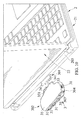
Fig. 1 is a perspective view of a portable electronic device with a connection kit for device peripherals in accordance with a first embodiment of the present invention, with the connection kit in a stowed position. -
Fig. 2 is another perspective view of the portable electronic device with the connection kit ofFig. 1 , with the connection kit in a use position. -
Fig. 3 is an exploded perspective view of the portable electronic device with the connection kit ofFig. 1 . -
Fig. 4 is an exploded perspective view of the portable electronic device with the connection kit, taken from a different angle of view ofFig. 3 . -
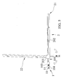
Fig. 5 illustrates the operation of the connection kit moved from the stowed position to the use position. -
Fig. 6 is a partial cross-sectional view ofFig. 1 . -
Fig. 7 is a partial cross-sectional view showing the connection kit in a position between the use and stowed positions. -
Fig. 8 is a partial cross-section view ofFig. 2 . -
Fig. 9 is an extended view ofFig. 2 , showing the connection kit adapted to electrically engaging and communicating with a plurality of device peripherals. -
Fig. 10 is a perspective view of a portable electronic device with a connection kit for device peripherals in accordance with a second embodiment of the present invention, with the connection kit in a use position. -
Fig. 11 is another perspective view of the portable electronic device with the connection kit ofFig. 10 , with the connection kit in a stowed position. -
Fig. 12 is a perspective view of a portable electronic device with a connection kit for device peripherals in accordance with a third embodiment of the present invention, with the connection kit in a use position. -
Figs. 1 through 9 show a portable electronic device with a connection kit for device peripherals including aconnection kit 1 and a portableelectronic device 2. - The connecting
kit 1 includes afirst end 101 and asecond end 102. Theconnection kit 1 includes a plurality ofinterface connectors 11 for electronically engaging and communicating with a plurality of device peripherals. In the embodiment, the plurality ofinterface connectors 11 show a USB type, an audio cable type, and an Ethernet cable type. However, any types of interface connectors are within the scope of the invention. - The portable
electronic device 2 includes aninput device 21 and amonitor 22. Theinput device 21 is pivotally engaged with themonitor 22. Themonitor 22 is pivotal to a first position that is overlapped and parallel with theinput device 21 and a second position that is inclined with respect to theinput device 21. Moreover, the portableelectronic device 2 includes achamber 201 extended therein and defines abottom side 202 and alateral side 203. Thechamber 201 forms a first open end on thebottom side 202 and a second open end on thelateral side 203 respectively. Thelateral side 203 determines a contour of the portableelectronic device 2. The portableelectronic device 2 put on a supporting surface includes thebottom side 202 abutted against the supporting surface. - Furthermore, the
chamber 201 defines a first depth to thebottom side 202 and theconnection kit 1 defines a second depth respectively. Theconnection kit 1 defines atop edge 103, abottom edge 104 and includes the second depth determining a distance between the top andbottom edges connection kit 1 also defines a lateral edge, which extends from thetop edge 103 to thebottom edge 104 and determines the second depth. The plurality ofinterface connectors 11 are disposed on the lateral edge of theconnection kit 1. - The connecting
kit 1 is electrically and pivotally engaged with the portableelectronic device 2. Awire 13 has a first distal end electrically connected to theconnection kit 1 and a second distal end electrically connected to the portableelectronic device 2. Theconnection kit 1 defines at least one first connectingsection 12 at thefirst end 101 and thechamber 201 defines at least one second connectingsection 204 respectively. The at least one first connectingsection 12 and the at least one second connectingsection 204 are pivotally engaged with each other to allow theconnection kit 1 to pivotally engage with the portableelectronic device 2. The at least one first connectingsection 12 forms a projection. The at least one second connectingsection 204 is in the shape of a hole. - The connecting
kit 1 is pivotal between a use position that is extended outside thechamber 201 and the contour of the portableelectronic device 2 and in which the plurality of device peripherals are adapted to be engaged and communicating therewith, and a stowed position that is accommodated in and not extended outside thechamber 201. -
Figs. 10 and11 show a portable electronic device with a connection kit for device peripherals in accordance with a second embodiment of the present invention. Aconnection kit 3 is used in lieu of theconnection kit 1. Theconnection kit 3 includes first and second ends 301 and 302. Likewise, theconnection kit 3 defines a third depth and also defines atop edge 303 and abottom edge 304 and includes the third depth determining a distance between the top andbottom edges connection kit 3 includes first andsecond bodies second bodies first body 34 is defined on thefirst end 301 and thesecond body 35 is defined on thesecond end 302 of theconnection kit 3 respectively. Theconnection kit 3 is pivotally engaged with the portable theelectronic device 2 by thefirst body 34. Further, at least oneinterface connector 31 is disposed in thesecond body 35. Thefirst body 34 defines a first joiningend 341 and thesecond body 35 defines a second joiningend 351 respectively. The first andsecond bodies end 341 engaged with the second joiningend 351 and the first andsecond bodies end 351 disengaged from the second joining end 352 respectively. The first andsecond bodies cable 33 extended therebetween and being stretched when thesecond body 35 is detached from thefirst body 34. Moreover, the first andsecond bodies cable 33. Thecable 33 has an arcuate cross section. -
Fig. 12 shows a portable electronic device with a connection kit for device peripherals in accordance with a third embodiment of the present invention. Acable 36 is used in lieu of thecable 33. Thecable 36 is a flexible flat cable that consists of a flat and flexible plastic film base and one surface including multiple metallic conductors bonded thereto. - In view of the forgoing, each of the
connection kits electronic device 2 engaged therewith and would not inhibit theelectronic devices 2 from dissipating heat. Consequently, when theelectronic device 2 is put on a supporting surface and theconnection kit chamber 201 provides a space, thus allowing theelectronic device 2 to dissipate heat easily and effectively. Moreover, each of theconnection kits connection kit - While the specific embodiments have been illustrated and described, numerous modifications come to mind without significantly departing from the spirit of invention and the scope of invention is only limited by the scope of accompanying claims.
Claims (10)
- A portable electronic device with a connection kit for device peripherals comprising:a connection kit (1, 3) including at least one interface connector (11, 31) for electrically engaging and communicating with at least one device peripheral; anda portable electronic device (2) including a chamber (201) extended therein, with the portable electronic device defining a bottom side (202) and a lateral side (203), with the chamber (201) forming a first open end on the bottom side (202) and a second open end on the lateral side (203) respectively, with the lateral side (203) determining a contour of the portable electronic device;wherein the connecting kit (1, 3) is electrically and pivotally engaged with the portable electronic device and pivotal between a use position that is extended outside the chamber (201) and the contour of the portable electronic device and in which the at least one device peripheral is adapted to be engaged and communicating therewith, and a stowed position that is accommodated in and not extended outside the chamber (201).
- The portable electronic device with the connection kit for device peripherals as claimed in claim 1, wherein the connection kit (3) includes first and second bodies (34, 35), with the first and second bodies (34, 35) releasably joined together, with the connection kit (3) pivotally engaged with the portable the electronic device (2) by the first body (34), with the at least one interface connector (31) disposed in the second body (35), with the first body (34) defining a first joining end (341) and the second body defining a second joining end (351) respectively, with the first and second bodies (34, 35) joined together including the first joining end (341) engaged with the second joining end (351) and the first and second bodies detached (34, 35) including the first joining end (341) disengaged from the second joining end (351) respectively, with the first and second bodies (34, 35)including a cable (33, 36) extended therebetween and being stretched when the second body (35) is detached from the first body (34), with the first and second bodies (34, 35) interconnected electrically by the cable (33, 36).
- The portable electronic device with the connection kit for device peripherals as claimed in claim 1, wherein the at least one interface connector (11, 31) includes a USB interface type, or an audio cable type, or an Ethernet cable type.
- The portable electronic device with the connection kit for device peripherals as claimed in claim1, wherein the at least one interface connector (11, 31) includes a plurality of interface connectors, wherein the connection kit (1,3) defines a top edge (103, 303), a bottom edge (104, 304) and includes a depth determining a distance between the top and bottom edges (303, 304), wherein the connection kit (1, 3) defines a lateral edge, which is extended from the top edge (103, 303) to the bottom edge (104, 304) and determines the depth, wherein the plurality of interface connectors (11, 31) are disposed on the lateral edge of the connection kit (1, 3).
- The portable electronic device with the connection kit for device peripherals as claimed in claim 4, wherein the plurality of interface connectors (11, 31) include a USB interface type, or an audio cable type, or an Ethernet cable type, or a collection thereof.
- The portable electronic device with the connection kit for device peripherals as claimed in claim 1, wherein the connection kit (1) defines at least one first connecting section (12) and the chamber (201) defines at least one second connecting section (204) respectively, with the at least one first connecting section (12) and the at least one second connecting section (204) pivotally engaged with each other to allow the connection kit (1) to pivotally engage with the portable electronic device (2).
- The portable electronic device with the connection kit for device peripherals as claimed in claim 6, wherein one of the at least one first and second connecting sections (12, 204) forms a projection, with the other of the at least one first and second connecting sections (12, 204) in the shape of a hole.
- The portable electronic device with the connection kit for device peripherals as claimed in claim 1, wherein the portable electronic device (2) includes an input device (21) and a monitor (22), with the input device pivotally engaged with the monitor (22), with the monitor (22) pivotal to a first position that is overlapped and parallel with the input device (21) and a second position that is inclined with respect to the input device (21).
- The portable electronic device with the connection kit for device peripherals as claimed in claim 2, wherein the portable electronic device (2) includes an input device (21) and a monitor (22), with the input device pivotally engaged with the monitor (22), with the monitor (22) pivotal to a first position that is overlapped and parallel with the input device (21) and a second position that is inclined with respect to the input device (21).
- The portable electronic device with the connection kit for device peripherals as claimed in claim 4, wherein the portable electronic device (2) includes an input device (21) and a monitor (22), with the input device pivotally engaged with the monitor (22), with the monitor (22) pivotal to a first position that is overlapped and parallel with the input device (21) and a second position that is inclined with respect to the input device (21).
Applications Claiming Priority (1)
| Application Number | Priority Date | Filing Date | Title |
|---|---|---|---|
| TW100128895A TW201308047A (en) | 2011-08-12 | 2011-08-12 | Connector for portable electronic device |
Publications (1)
| Publication Number | Publication Date |
|---|---|
| EP2557474A1 true EP2557474A1 (en) | 2013-02-13 |
Family
ID=45418416
Family Applications (1)
| Application Number | Title | Priority Date | Filing Date |
|---|---|---|---|
| EP11193742A Withdrawn EP2557474A1 (en) | 2011-08-12 | 2011-12-15 | Portable electronic device with connection kit for device peripherals |
Country Status (3)
| Country | Link |
|---|---|
| US (1) | US20130038987A1 (en) |
| EP (1) | EP2557474A1 (en) |
| TW (1) | TW201308047A (en) |
Citations (5)
| Publication number | Priority date | Publication date | Assignee | Title |
|---|---|---|---|---|
| DE8909095U1 (en) * | 1989-07-24 | 1990-09-20 | Siemens AG, 1000 Berlin und 8000 München | Data processing device |
| US6093038A (en) * | 1998-11-28 | 2000-07-25 | Inventec Corp. | Movable connector board for computer |
| US6290517B1 (en) * | 1999-08-17 | 2001-09-18 | Gateway, Inc. | Fold out port group for portable computer |
| US20070077797A1 (en) * | 2005-09-30 | 2007-04-05 | Gavin Reid | Connection system |
| WO2009105101A1 (en) * | 2008-02-21 | 2009-08-27 | Hewlett-Packard Development Company, L.P. | Computing devices having pop-out connector port arrays |
-
2011
- 2011-08-12 TW TW100128895A patent/TW201308047A/en unknown
- 2011-11-28 US US13/304,745 patent/US20130038987A1/en not_active Abandoned
- 2011-12-15 EP EP11193742A patent/EP2557474A1/en not_active Withdrawn
Patent Citations (5)
| Publication number | Priority date | Publication date | Assignee | Title |
|---|---|---|---|---|
| DE8909095U1 (en) * | 1989-07-24 | 1990-09-20 | Siemens AG, 1000 Berlin und 8000 München | Data processing device |
| US6093038A (en) * | 1998-11-28 | 2000-07-25 | Inventec Corp. | Movable connector board for computer |
| US6290517B1 (en) * | 1999-08-17 | 2001-09-18 | Gateway, Inc. | Fold out port group for portable computer |
| US20070077797A1 (en) * | 2005-09-30 | 2007-04-05 | Gavin Reid | Connection system |
| WO2009105101A1 (en) * | 2008-02-21 | 2009-08-27 | Hewlett-Packard Development Company, L.P. | Computing devices having pop-out connector port arrays |
Also Published As
| Publication number | Publication date |
|---|---|
| US20130038987A1 (en) | 2013-02-14 |
| TW201308047A (en) | 2013-02-16 |
Similar Documents
| Publication | Publication Date | Title |
|---|---|---|
| USD864969S1 (en) | Card PC | |
| US9397717B2 (en) | Electronic device gripping system | |
| US9301584B2 (en) | Carrying case assembly | |
| USD652229S1 (en) | Classroom desk | |
| USD803826S1 (en) | Laptop computer | |
| USD731969S1 (en) | Portable power adapter and converter | |
| USD699144S1 (en) | Lanyard connector | |
| USD862206S1 (en) | Electrical extension cord organizer and storage device | |
| US20150001113A1 (en) | Structure of Tool Holding Sheath Cross Reference To Related Application | |
| USD981408S1 (en) | Portable computer | |
| US20180295908A1 (en) | Electronic Device Holding System | |
| USD700610S1 (en) | Portable device holder with a hand compartment | |
| US9795850B1 (en) | Ball striking training device | |
| US9119308B2 (en) | Cover | |
| US20110164374A1 (en) | Portable storage device | |
| US20130038987A1 (en) | Portable Electronic Device with Connection Kit for Device Peripherals | |
| CN104571646A (en) | Portable multifunctional mouse pad table | |
| USD891835S1 (en) | Device for holding portable electronics | |
| US20150165616A1 (en) | Holding unit for sockets | |
| US20140283341A1 (en) | Cable clamp | |
| US20110016650A1 (en) | Cleaning tool | |
| US10027151B2 (en) | Smart phone charging system | |
| US11219299B1 (en) | Electronic tablet holder assembly | |
| CN204391644U (en) | A wire arrangement device with good fixing effect | |
| TWM435426U (en) | Jig |
Legal Events
| Date | Code | Title | Description |
|---|---|---|---|
| PUAI | Public reference made under article 153(3) epc to a published international application that has entered the european phase |
Free format text: ORIGINAL CODE: 0009012 |
|
| AK | Designated contracting states |
Kind code of ref document: A1 Designated state(s): AL AT BE BG CH CY CZ DE DK EE ES FI FR GB GR HR HU IE IS IT LI LT LU LV MC MK MT NL NO PL PT RO RS SE SI SK SM TR |
|
| AX | Request for extension of the european patent |
Extension state: BA ME |
|
| 17P | Request for examination filed |
Effective date: 20130131 |
|
| STAA | Information on the status of an ep patent application or granted ep patent |
Free format text: STATUS: THE APPLICATION IS DEEMED TO BE WITHDRAWN |
|
| 18D | Application deemed to be withdrawn |
Effective date: 20140701 |