EP2557407A2 - Pressure sensor - Google Patents
Pressure sensor Download PDFInfo
- Publication number
- EP2557407A2 EP2557407A2 EP12179708A EP12179708A EP2557407A2 EP 2557407 A2 EP2557407 A2 EP 2557407A2 EP 12179708 A EP12179708 A EP 12179708A EP 12179708 A EP12179708 A EP 12179708A EP 2557407 A2 EP2557407 A2 EP 2557407A2
- Authority
- EP
- European Patent Office
- Prior art keywords
- movable member
- pressure
- housing
- fluid
- sensor
- Prior art date
- Legal status (The legal status is an assumption and is not a legal conclusion. Google has not performed a legal analysis and makes no representation as to the accuracy of the status listed.)
- Granted
Links
Images




Classifications
-
- G—PHYSICS
- G01—MEASURING; TESTING
- G01L—MEASURING FORCE, STRESS, TORQUE, WORK, MECHANICAL POWER, MECHANICAL EFFICIENCY, OR FLUID PRESSURE
- G01L9/00—Measuring steady of quasi-steady pressure of fluid or fluent solid material by electric or magnetic pressure-sensitive elements; Transmitting or indicating the displacement of mechanical pressure-sensitive elements, used to measure the steady or quasi-steady pressure of a fluid or fluent solid material, by electric or magnetic means
- G01L9/0041—Transmitting or indicating the displacement of flexible diaphragms
- G01L9/0076—Transmitting or indicating the displacement of flexible diaphragms using photoelectric means
-
- A—HUMAN NECESSITIES
- A61—MEDICAL OR VETERINARY SCIENCE; HYGIENE
- A61M—DEVICES FOR INTRODUCING MEDIA INTO, OR ONTO, THE BODY; DEVICES FOR TRANSDUCING BODY MEDIA OR FOR TAKING MEDIA FROM THE BODY; DEVICES FOR PRODUCING OR ENDING SLEEP OR STUPOR
- A61M1/00—Suction or pumping devices for medical purposes; Devices for carrying-off, for treatment of, or for carrying-over, body-liquids; Drainage systems
- A61M1/36—Other treatment of blood in a by-pass of the natural circulatory system, e.g. temperature adaptation, irradiation ; Extra-corporeal blood circuits
- A61M1/3621—Extra-corporeal blood circuits
- A61M1/3622—Extra-corporeal blood circuits with a cassette forming partially or totally the blood circuit
-
- A—HUMAN NECESSITIES
- A61—MEDICAL OR VETERINARY SCIENCE; HYGIENE
- A61M—DEVICES FOR INTRODUCING MEDIA INTO, OR ONTO, THE BODY; DEVICES FOR TRANSDUCING BODY MEDIA OR FOR TAKING MEDIA FROM THE BODY; DEVICES FOR PRODUCING OR ENDING SLEEP OR STUPOR
- A61M1/00—Suction or pumping devices for medical purposes; Devices for carrying-off, for treatment of, or for carrying-over, body-liquids; Drainage systems
- A61M1/36—Other treatment of blood in a by-pass of the natural circulatory system, e.g. temperature adaptation, irradiation ; Extra-corporeal blood circuits
- A61M1/3621—Extra-corporeal blood circuits
- A61M1/3622—Extra-corporeal blood circuits with a cassette forming partially or totally the blood circuit
- A61M1/36222—Details related to the interface between cassette and machine
- A61M1/362227—Details related to the interface between cassette and machine the interface providing means for actuating on functional elements of the cassette, e.g. plungers
-
- A—HUMAN NECESSITIES
- A61—MEDICAL OR VETERINARY SCIENCE; HYGIENE
- A61M—DEVICES FOR INTRODUCING MEDIA INTO, OR ONTO, THE BODY; DEVICES FOR TRANSDUCING BODY MEDIA OR FOR TAKING MEDIA FROM THE BODY; DEVICES FOR PRODUCING OR ENDING SLEEP OR STUPOR
- A61M1/00—Suction or pumping devices for medical purposes; Devices for carrying-off, for treatment of, or for carrying-over, body-liquids; Drainage systems
- A61M1/36—Other treatment of blood in a by-pass of the natural circulatory system, e.g. temperature adaptation, irradiation ; Extra-corporeal blood circuits
- A61M1/3621—Extra-corporeal blood circuits
- A61M1/3622—Extra-corporeal blood circuits with a cassette forming partially or totally the blood circuit
- A61M1/36224—Extra-corporeal blood circuits with a cassette forming partially or totally the blood circuit with sensing means or components thereof
-
- A—HUMAN NECESSITIES
- A61—MEDICAL OR VETERINARY SCIENCE; HYGIENE
- A61M—DEVICES FOR INTRODUCING MEDIA INTO, OR ONTO, THE BODY; DEVICES FOR TRANSDUCING BODY MEDIA OR FOR TAKING MEDIA FROM THE BODY; DEVICES FOR PRODUCING OR ENDING SLEEP OR STUPOR
- A61M1/00—Suction or pumping devices for medical purposes; Devices for carrying-off, for treatment of, or for carrying-over, body-liquids; Drainage systems
- A61M1/36—Other treatment of blood in a by-pass of the natural circulatory system, e.g. temperature adaptation, irradiation ; Extra-corporeal blood circuits
- A61M1/3621—Extra-corporeal blood circuits
- A61M1/3639—Blood pressure control, pressure transducers specially adapted therefor
-
- A—HUMAN NECESSITIES
- A61—MEDICAL OR VETERINARY SCIENCE; HYGIENE
- A61M—DEVICES FOR INTRODUCING MEDIA INTO, OR ONTO, THE BODY; DEVICES FOR TRANSDUCING BODY MEDIA OR FOR TAKING MEDIA FROM THE BODY; DEVICES FOR PRODUCING OR ENDING SLEEP OR STUPOR
- A61M1/00—Suction or pumping devices for medical purposes; Devices for carrying-off, for treatment of, or for carrying-over, body-liquids; Drainage systems
- A61M1/36—Other treatment of blood in a by-pass of the natural circulatory system, e.g. temperature adaptation, irradiation ; Extra-corporeal blood circuits
- A61M1/3621—Extra-corporeal blood circuits
- A61M1/3639—Blood pressure control, pressure transducers specially adapted therefor
- A61M1/3641—Pressure isolators
-
- G—PHYSICS
- G01—MEASURING; TESTING
- G01L—MEASURING FORCE, STRESS, TORQUE, WORK, MECHANICAL POWER, MECHANICAL EFFICIENCY, OR FLUID PRESSURE
- G01L19/00—Details of, or accessories for, apparatus for measuring steady or quasi-steady pressure of a fluent medium insofar as such details or accessories are not special to particular types of pressure gauges
- G01L19/0092—Pressure sensor associated with other sensors, e.g. for measuring acceleration or temperature
-
- A—HUMAN NECESSITIES
- A61—MEDICAL OR VETERINARY SCIENCE; HYGIENE
- A61M—DEVICES FOR INTRODUCING MEDIA INTO, OR ONTO, THE BODY; DEVICES FOR TRANSDUCING BODY MEDIA OR FOR TAKING MEDIA FROM THE BODY; DEVICES FOR PRODUCING OR ENDING SLEEP OR STUPOR
- A61M1/00—Suction or pumping devices for medical purposes; Devices for carrying-off, for treatment of, or for carrying-over, body-liquids; Drainage systems
- A61M1/36—Other treatment of blood in a by-pass of the natural circulatory system, e.g. temperature adaptation, irradiation ; Extra-corporeal blood circuits
- A61M1/3621—Extra-corporeal blood circuits
- A61M1/3622—Extra-corporeal blood circuits with a cassette forming partially or totally the blood circuit
- A61M1/36226—Constructional details of cassettes, e.g. specific details on material or shape
- A61M1/362261—Constructional details of cassettes, e.g. specific details on material or shape at least one cassette surface or portion thereof being flexible, e.g. the cassette having a rigid base portion with preformed channels and being covered with a foil
-
- A—HUMAN NECESSITIES
- A61—MEDICAL OR VETERINARY SCIENCE; HYGIENE
- A61M—DEVICES FOR INTRODUCING MEDIA INTO, OR ONTO, THE BODY; DEVICES FOR TRANSDUCING BODY MEDIA OR FOR TAKING MEDIA FROM THE BODY; DEVICES FOR PRODUCING OR ENDING SLEEP OR STUPOR
- A61M2205/00—General characteristics of the apparatus
- A61M2205/33—Controlling, regulating or measuring
- A61M2205/3306—Optical measuring means
-
- A—HUMAN NECESSITIES
- A61—MEDICAL OR VETERINARY SCIENCE; HYGIENE
- A61M—DEVICES FOR INTRODUCING MEDIA INTO, OR ONTO, THE BODY; DEVICES FOR TRANSDUCING BODY MEDIA OR FOR TAKING MEDIA FROM THE BODY; DEVICES FOR PRODUCING OR ENDING SLEEP OR STUPOR
- A61M2205/00—General characteristics of the apparatus
- A61M2205/33—Controlling, regulating or measuring
- A61M2205/3368—Temperature
- A61M2205/3372—Temperature compensation
Definitions
- the present invention relates generally to a pressure sensor for a fluid (e.g., a gas or liquid).
- a fluid e.g., a gas or liquid.
- a wide variety of mechanisms may be used to detect the pressure of a fluid, including a piezoelectric mechanism, a potentiometer, an electromagnetic mechanism, a capacitor, or a piezoresistive mechanism.
- a disposable pressure sensor may be utilized.
- a pressure sensor may be utilized in a machine that handles blood, such as a centrifuge that separates blood into its various therapeutic components, (e.g., red blood cells, platelets, plasma, etc.).
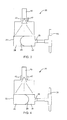
- FIG. 1 is a side view of a pressure sensor in an initial or calibration state, according to an exemplary embodiment.
- FIG. 2 is a cross-section view of the pressure sensor of FIG. 1 taken along line 2-2, according to an exemplary embodiment.
- FIG. 3 is a side view of the pressure sensor of FIG. 1 in a positive pressure-sensing state, according to an exemplary embodiment.
- FIG. 4 is a side view of the pressure sensor of FIG. 1 in a negative pressure-sensing state, according to an exemplary embodiment.
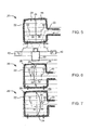
- FIG. 5 is a side view of a pressure sensor in an initial or calibration state showing elements for calculating displacement, according to an exemplary embodiment.
- FIG. 6 is a side view of the pressure sensor of FIG. 5 in a positive pressure-sensing state, according to an exemplary embodiment.
- FIG. 7 is a side view of the pressure sensor of FIG. 5 in a negative pressure-sensing state, according to an exemplary embodiment.
- FIG. 8 is an exploded view of a disposable fluid processing assembly usable in association with a centrifuge assembly.
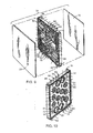
- FIG. 9 is a rear isometric exploded view of a fluid control cassette that may be incorporated by the fluid processing assembly of FIG. 8 .
- FIG. 10 is a front isometric view of the fluid control cassette of FIG. 9 .
- FIG. 11 is an isometric view of a cassette holding station for a centrifuge, according to an exemplary embodiment.
- FIG. 12 is a flowchart of a method for measuring the pressure of a fluid, according to an exemplary embodiment.
- the sensor 20 is configured to monitor the pressure of a fluid.
- Sensor 20 may be utilized as a part of a larger system.
- Sensor 20 includes a generally hollow housing 22 with an aperture 23 configured to receive a fluid.
- the fluid may be contained in a fluid system 50.
- a movable member 24 is disposed in the housing, separating the interior of the housing into a first chamber 26 in fluid communication with aperture 23 and a second chamber 28.
- a periphery of movable member 24 may be coupled to the interior of housing 22.
- the interior ofhousing 22 may be separated into first chamber 26 and second chamber 28 by a stationary rigid wall.
- Movable member 24 is configured to move in response to a pressure of the fluid admitted into first chamber 26 through aperture 23.
- movable member 24 is a flexible membrane or film that is formed from an elastomeric or other flexible material.
- the membrane is made from a flexible material that does not yield and remains flexible. Pressure exerted on the membrane forces the membrane to deform relative to a base configuration in which an equal pressure is being exerted on the membrane from first chamber 26 and second chamber 28. If the pressure in first chamber 26 is less than the pressure in second chamber 28 (e.g., a vacuum or negative pressure in fluid system 50), the membrane is deformed into first chamber 26. If the pressure in first chamber 26 is greater than the pressure in second chamber 28 (e.g., a positive pressure in fluid system 50), the membrane is deformed into second chamber 28. The magnitude of the pressure in fluid system 50 (e.g., the pressure differential between first chamber 26 and second chamber 28) is proportional to the relative deformation or displacement of movable member 24.
- the pressure in fluid system 50 e.g., the pressure differential between first chamber 26 and second chamber 28
- movable member 24 may be a relatively rigid device, such as a shuttle, rigid capsule, or a ball bearing that is confined, for example, by a track or tube in fluid communication with first chamber 26 and second chamber 28.
- a rigid movable member 24 may be configured to move back and forth along the track or tube in response to a pressure differential between first chamber 26 and second chamber 28.
- Housing 22 includes a transparent portion to allow movable member 24 to be visible from outside housing 22.
- the deformation or displacement of movable member 24 is detected and monitored by a vision or optical sensor 40 (e.g., a camera, a CCD line sensor, a pin diode detector, a multi-dimensional sensor or array, etc).
- Vision sensor 40 captures images of movable member 24 that may be analyzed by a computer or other device to detect changes in position of movable member 24 (e.g., deflection, deformation, distortion, translation, etc.) to determine the pressure of fluid system 50.
- Vision sensor 40 is positioned and may have a field of vision wide enough that is able to capture the full range of motion of movable member 24 or may alternatively capture only a portion of the range of motion of the movable member.
- sensor 20 further includes a temperature sensor 42, such as a laser thermocouple or another temperature sensor that is capable of non-contact or non-invasive temperature readings.
- Temperature sensor 42 monitors the temperature in first chamber 26 and/or second chamber 28 so that sensor 20 can compensate for temperature differences when calculating the pressure of fluid system 50.
- a sensor 20 is shown according to another exemplary embodiment.
- Vision sensor 40 may monitor displacement of movable member 24 relative to one or more reference marks 30 and 32.
- a first reference mark 30 may be provided in first chamber 26 and a second reference mark 32 may be provided in second chamber 28.
- first reference mark 30 and/or second reference mark 32 may be formed on the exterior of housing 22, on a transparent portion of housing such as a window, or at another location of sensor 20.
- Vision sensor 40 may capture an image when sensor 20 is coupled to an open fluid system 50. This image and/or data about the image may then be stored and utilized as a zero condition (e.g., base position, reference position, etc.). Vision sensor 40 may utilize a first distance 36 between the peak point 34 of movable member 24 and first reference mark 30 and/or a second distance 38 between peak point 34 and second reference mark 32 to determine the displacement of movable member 24. If the pressure in first chamber 26 is equal to the pressure in second chamber 28, peak point 34 may be an equal distance from first reference mark 30 and second reference mark 32. If the pressures in first chamber 26 and second chamber 28 are not equal, peak point 34 may be closer to first reference mark 30 or second reference mark 32 as the zero condition. In one embodiment, sensor 40 is coupled to a processing circuit which is configured to take a reference point for the zero condition and detect any deflection on either side of the diaphragm to represent a change from the zero condition.
- a processing circuit which is configured to take a reference point for the zero condition and detect any
- Measurements of fluid pressure in fluid system 50 may be determined by analyzing the difference in position of peak point 34 from the zero condition position. If a negative pressure is present in fluid system 50, peak point 34 will move closer to first reference mark 30, resulting in first distance 36 decreasing and second distance 38 increasing. If a positive pressure is present in fluid system 50, peak point will move closer to second reference mark 32, resulting in first distance 36 increasing and second distance 38 decreasing. In various embodiments, the displacement of movable member 24 and the pressure in fluid system 50 may be determined by analyzing the difference in first distance 36, second distance 38, or a ratio of first distance 36 and second distance 38.
- Vision sensor 40 provides a flexible manner of establishing a zero condition and measuring the displacement of movable member 24.
- Sensor 20 is automatically calibrated with vision sensor 40. Unlike sensors with a mechanical interconnection, sensor 20 does not have to be physically coupled with vision sensor 40 or precisely aligned with vision sensor 40.
- Vision sensor 40 can record a zero condition and compensate if housing 22 moves, or if movable member 24 is displaced because of an initial or preconditioned pressure difference. Such a preconditioned pressure difference may be the result of, for example, shipping, environmental changes, or previous usage.
- vision sensor 40 of sensor 20 may be coupled to a processing circuit 44.
- Processing circuit 44 is configured to calculate the pressure of fluid system 50 based on signals received from the vision sensor 40 and temperature sensors 42.
- Processing sensor 44 may further be coupled to a display 46 to output the calculated pressure readings to a user.
- a user input device 48 may be provided to allow a user to interact with sensor 20 (e.g., by performing diagnostic tests, establishing a reference or zero condition, etc.).
- fluid system 50 may be utilized in a blood processing system to process whole blood or other suspensions of biological material.
- the blood processing system may include a first portion or housing configured to be reused for multiple blood processing operations for different patients, and a second portion or housing configured for a single blood processing operation.
- the first portion may be a device such as a centrifuge and the second portion may be a disposable fluid system 50 (e.g., a fluid processing assembly).
- Fluid system 50 is insertable to and removable from the centrifuge.
- Fluid system 50 includes conduits 52 configured to convey fluid through fluid system to and from the centrifuge or other mechanism.
- Fluid system 50 further includes one or more cassettes 54 that direct liquid flow among multiple fluid sources and destinations during a fluid processing procedure.
- a movable member 24 is disposed in the cassettes 54. As described above, movable member 24 is configured to move in response to a change in pressure of the blood in fluid system 50.
- cassettes 54 have a body or housing 60 that is formed to include one or more input ports 62, one or more output ports 64, and channels 66 that direct fluid from inputs 62 to outputs 64.
- a cover or panel 68 is coupled to one side of housing 60 while a flexible diaphragm or membrane 70 is coupled to the opposite side of housing 60.
- Housing 60 further forms one or more open-ended sensing portions 72.
- Sensing portions 72 are analogous to first chamber 26 of sensor 20 described above.
- Apertures 61 in housing 60 allow sensing portions 68 to be in fluid communication with channels 66.
- the open end of each sensing portion 68 is sealed by membrane 70 (e.g., with an ultrasonic welding operation, a vacuum, etc.). In this way, membrane 70 serves the same function as movable member 24 of sensor 20 described above.
- each cassette 54 is received in a holder 80 in the centrifuge.
- Holder 80 may include actuators 82 that interact with aligned valves in cassettes 54, and vision sensors to sense the displacement of membrane 70 proximate to sensing portions 72.
- Vision sensors may be provided adjacent to chambers 84 (e.g., hollows, recesses, cavities, etc.) formed in holder 80 that are aligned with sensing portions 72 of cassette 54. Chambers 84 in holder 80 may therefore be analogous to second chamber 28 of sensor 20 described above.
- Vision sensors may be mounted perpendicular to the moving diaphragm or sheeting for optimal deflection. In the case of an apheresis machine as shown partially in FIG. 11 , the camera lens can be installed in a boss from a top panel of the machine. The vision sensor would be focused onto the side of the cassette to monitor deflection of the film.
- the vision sensor may capture an image of membrane 70 to establish a reference or zero condition.
- Cassette 54 includes a transparent portion proximate to each sensor portion 72 to allow the vision sensor to monitor membrane 70.
- the position of membrane 70 may be calculated relative to reference marks provided on holder 80 and/or cassette 54.
- the vision sensor may then generate a signal indicative of the movement and transmit the signal to a processing circuit coupled to the vision system configured to calculate a pressure of the blood in various channels 66. This data may be used for various other processes associated with the blood processing system, such as operating valves in cassettes 54 using actuators.
- Holder 80 may further collect temperature data using non-contact temperature sensors as described above.
- a fluid is first channeled into a housing to a movable member (step 92).
- the movable member is displaced or deformed in response to a change in pressure of the fluid (step 94).
- the movable member may be a flexible member that is moved in a first direction in response to an increase in pressure in the fluid and moved in a second direction opposite the first direction in response to a decrease in pressure of the fluid.
- the displacement or deformation of the movable member is detected with a camera or other vision sensor (step 96).
- the displacement of the movable member may be detected, for example, through a transparent portion of a housing within which the movable member is disposed.
- the temperature of the fluid may be measured (step 98).
- a pressure signal may be generated based on the detected movement of the movable member and the measured temperature of the fluid (step 99).
- Some embodiments may provide for noninvasive, extracorporeal pressure monitoring of a fluid, such as blood. Monitored pressure data may be utilized to facilitate the processing of the fluid, such as the separation of blood into its component parts.
- Some embodiments may provide a low cost pressure sensor for systems in which some of the system is configured to be disposable.
- sensor 20 is configured to include a portion interacting with the fluid (e.g., housing 22 and movable member 24) that is relatively low cost that separates from a second portion that includes more expensive components (e.g., vision sensor 40, temperature sensors 42, etc.). The lower cost components may then be disposed of after each use while the more expensive components are retained to be used multiple times.
- Some embodiments may provide a pressure sensor with a disposable portion and a non-disposable portion that do not require physical coupling or precise positioning to function correctly. In this way, the installation of a new disposable portion may be accomplished quickly and easily without negatively effecting the accuracy of data collected with the pressure sensor.
- Some embodiments may provide a mechanism for sensing pressure that can easily compensate for environmental variations and physical misalignments by providing an adaptable system for establishing a reference or zero condition.
- the processing circuit may comprise any digital and/or analog circuit components configured to perform the functions recited herein.
- the processing circuit may comprise one or more modules, units, circuits, etc., may comprise a microprocessor, microcontroller, application-specific integrated circuit, programmable logic, or other circuitry.
- the processing circuit may comprise a tangible computer-readable memory having instructions encoded thereon which when processed by a processor perform the functions recited herein.
- the word "exemplary” is used to mean serving as an example, instance or illustration. Any embodiment or design described herein as "exemplary” is not necessarily to be construed as preferred or advantageous over other embodiments or designs. Rather, use of the word exemplary is intended to present concepts in a concrete manner. Accordingly, all such modifications are intended to be included within the scope of the present inventions. Other substitutions, modifications, changes, and omissions may be made in the design, operating conditions, and arrangement of the preferred and other exemplary embodiments without departing from the spirit of the appended claims.
Landscapes
- Health & Medical Sciences (AREA)
- Heart & Thoracic Surgery (AREA)
- Vascular Medicine (AREA)
- Engineering & Computer Science (AREA)
- Animal Behavior & Ethology (AREA)
- Cardiology (AREA)
- Veterinary Medicine (AREA)
- Public Health (AREA)
- General Health & Medical Sciences (AREA)
- Anesthesiology (AREA)
- Biomedical Technology (AREA)
- Hematology (AREA)
- Life Sciences & Earth Sciences (AREA)
- General Physics & Mathematics (AREA)
- Physics & Mathematics (AREA)
- Chemical & Material Sciences (AREA)
- Analytical Chemistry (AREA)
- External Artificial Organs (AREA)
- Measuring Fluid Pressure (AREA)
Abstract
Description
- This application claims the benefit of
U.S. Provisional Application No. 61/523,001 filed August 12, 2011 - The present invention relates generally to a pressure sensor for a fluid (e.g., a gas or liquid). A wide variety of mechanisms may be used to detect the pressure of a fluid, including a piezoelectric mechanism, a potentiometer, an electromagnetic mechanism, a capacitor, or a piezoresistive mechanism.
- In some applications, a disposable pressure sensor may be utilized. For example, a pressure sensor may be utilized in a machine that handles blood, such as a centrifuge that separates blood into its various therapeutic components, (e.g., red blood cells, platelets, plasma, etc.).
- It would be advantageous to provide an improved disposable pressure sensor.
- These and other features, aspects, and advantages of the present invention will become apparent from the following description, appended claims, and the accompanying exemplary embodiments shown in the drawings, which are briefly described below.
-
FIG. 1 is a side view of a pressure sensor in an initial or calibration state, according to an exemplary embodiment. -
FIG. 2 is a cross-section view of the pressure sensor ofFIG. 1 taken along line 2-2, according to an exemplary embodiment. -
FIG. 3 is a side view of the pressure sensor ofFIG. 1 in a positive pressure-sensing state, according to an exemplary embodiment. -
FIG. 4 is a side view of the pressure sensor ofFIG. 1 in a negative pressure-sensing state, according to an exemplary embodiment. -
FIG. 5 is a side view of a pressure sensor in an initial or calibration state showing elements for calculating displacement, according to an exemplary embodiment. -
FIG. 6 is a side view of the pressure sensor ofFIG. 5 in a positive pressure-sensing state, according to an exemplary embodiment. -
FIG. 7 is a side view of the pressure sensor ofFIG. 5 in a negative pressure-sensing state, according to an exemplary embodiment. -
FIG. 8 is an exploded view of a disposable fluid processing assembly usable in association with a centrifuge assembly. -
FIG. 9 is a rear isometric exploded view of a fluid control cassette that may be incorporated by the fluid processing assembly ofFIG. 8 . -
FIG. 10 is a front isometric view of the fluid control cassette ofFIG. 9 . -
FIG. 11 is an isometric view of a cassette holding station for a centrifuge, according to an exemplary embodiment. -
FIG. 12 is a flowchart of a method for measuring the pressure of a fluid, according to an exemplary embodiment. - It is to be understood that the following detailed description is exemplary and explanatory only, and is not restrictive of the invention as claimed.
- Referring to
FIGS. 1-4 , one exemplary embodiment relates to asensor 20. Thesensor 20 is configured to monitor the pressure of a fluid.Sensor 20 may be utilized as a part of a larger system.Sensor 20 includes a generallyhollow housing 22 with anaperture 23 configured to receive a fluid. The fluid may be contained in afluid system 50. Amovable member 24 is disposed in the housing, separating the interior of the housing into afirst chamber 26 in fluid communication withaperture 23 and asecond chamber 28. According to one exemplary embodiment, a periphery ofmovable member 24 may be coupled to the interior ofhousing 22. According to another exemplary embodiment, the interior ofhousing 22 may be separated intofirst chamber 26 andsecond chamber 28 by a stationary rigid wall.Movable member 24 is configured to move in response to a pressure of the fluid admitted intofirst chamber 26 throughaperture 23. - According to one exemplary embodiment,
movable member 24 is a flexible membrane or film that is formed from an elastomeric or other flexible material. In one embodiment, the membrane is made from a flexible material that does not yield and remains flexible. Pressure exerted on the membrane forces the membrane to deform relative to a base configuration in which an equal pressure is being exerted on the membrane fromfirst chamber 26 andsecond chamber 28. If the pressure infirst chamber 26 is less than the pressure in second chamber 28 (e.g., a vacuum or negative pressure in fluid system 50), the membrane is deformed intofirst chamber 26. If the pressure infirst chamber 26 is greater than the pressure in second chamber 28 (e.g., a positive pressure in fluid system 50), the membrane is deformed intosecond chamber 28. The magnitude of the pressure in fluid system 50 (e.g., the pressure differential betweenfirst chamber 26 and second chamber 28) is proportional to the relative deformation or displacement ofmovable member 24. - In other exemplary embodiments,
movable member 24 may be a relatively rigid device, such as a shuttle, rigid capsule, or a ball bearing that is confined, for example, by a track or tube in fluid communication withfirst chamber 26 andsecond chamber 28. A rigidmovable member 24 may be configured to move back and forth along the track or tube in response to a pressure differential betweenfirst chamber 26 andsecond chamber 28. -
Housing 22 includes a transparent portion to allowmovable member 24 to be visible fromoutside housing 22. The deformation or displacement ofmovable member 24 is detected and monitored by a vision or optical sensor 40 (e.g., a camera, a CCD line sensor, a pin diode detector, a multi-dimensional sensor or array, etc).Vision sensor 40 captures images ofmovable member 24 that may be analyzed by a computer or other device to detect changes in position of movable member 24 (e.g., deflection, deformation, distortion, translation, etc.) to determine the pressure offluid system 50.Vision sensor 40 is positioned and may have a field of vision wide enough that is able to capture the full range of motion ofmovable member 24 or may alternatively capture only a portion of the range of motion of the movable member. - According to an exemplary embodiment,
sensor 20 further includes atemperature sensor 42, such as a laser thermocouple or another temperature sensor that is capable of non-contact or non-invasive temperature readings.Temperature sensor 42 monitors the temperature infirst chamber 26 and/orsecond chamber 28 so thatsensor 20 can compensate for temperature differences when calculating the pressure offluid system 50. - Referring to
FIGS. 5-7 , asensor 20 is shown according to another exemplary embodiment.Vision sensor 40 may monitor displacement ofmovable member 24 relative to one ormore reference marks first reference mark 30 may be provided infirst chamber 26 and asecond reference mark 32 may be provided insecond chamber 28. According to another exemplary embodiment,first reference mark 30 and/orsecond reference mark 32 may be formed on the exterior ofhousing 22, on a transparent portion of housing such as a window, or at another location ofsensor 20. -
Vision sensor 40 may capture an image whensensor 20 is coupled to anopen fluid system 50. This image and/or data about the image may then be stored and utilized as a zero condition (e.g., base position, reference position, etc.).Vision sensor 40 may utilize afirst distance 36 between thepeak point 34 ofmovable member 24 andfirst reference mark 30 and/or asecond distance 38 betweenpeak point 34 andsecond reference mark 32 to determine the displacement ofmovable member 24. If the pressure infirst chamber 26 is equal to the pressure insecond chamber 28,peak point 34 may be an equal distance fromfirst reference mark 30 andsecond reference mark 32. If the pressures infirst chamber 26 andsecond chamber 28 are not equal,peak point 34 may be closer tofirst reference mark 30 orsecond reference mark 32 as the zero condition. In one embodiment,sensor 40 is coupled to a processing circuit which is configured to take a reference point for the zero condition and detect any deflection on either side of the diaphragm to represent a change from the zero condition. - Measurements of fluid pressure in
fluid system 50 may be determined by analyzing the difference in position ofpeak point 34 from the zero condition position. If a negative pressure is present influid system 50,peak point 34 will move closer tofirst reference mark 30, resulting infirst distance 36 decreasing andsecond distance 38 increasing. If a positive pressure is present influid system 50, peak point will move closer tosecond reference mark 32, resulting infirst distance 36 increasing andsecond distance 38 decreasing. In various embodiments, the displacement ofmovable member 24 and the pressure influid system 50 may be determined by analyzing the difference infirst distance 36,second distance 38, or a ratio offirst distance 36 andsecond distance 38. -
Vision sensor 40 provides a flexible manner of establishing a zero condition and measuring the displacement ofmovable member 24.Sensor 20 is automatically calibrated withvision sensor 40. Unlike sensors with a mechanical interconnection,sensor 20 does not have to be physically coupled withvision sensor 40 or precisely aligned withvision sensor 40.Vision sensor 40 can record a zero condition and compensate ifhousing 22 moves, or ifmovable member 24 is displaced because of an initial or preconditioned pressure difference. Such a preconditioned pressure difference may be the result of, for example, shipping, environmental changes, or previous usage. - As shown in
FIG. 1 ,vision sensor 40 ofsensor 20 may be coupled to aprocessing circuit 44. Processingcircuit 44 is configured to calculate the pressure offluid system 50 based on signals received from thevision sensor 40 andtemperature sensors 42.Processing sensor 44 may further be coupled to adisplay 46 to output the calculated pressure readings to a user. Auser input device 48 may be provided to allow a user to interact with sensor 20 (e.g., by performing diagnostic tests, establishing a reference or zero condition, etc.). - Referring now to
FIG. 8 , according to one exemplary embodiment,fluid system 50 may be utilized in a blood processing system to process whole blood or other suspensions of biological material. To avoid cross-contamination between patients, the blood processing system may include a first portion or housing configured to be reused for multiple blood processing operations for different patients, and a second portion or housing configured for a single blood processing operation. According to one exemplary embodiment, the first portion may be a device such as a centrifuge and the second portion may be a disposable fluid system 50 (e.g., a fluid processing assembly).Fluid system 50 is insertable to and removable from the centrifuge.Fluid system 50 includesconduits 52 configured to convey fluid through fluid system to and from the centrifuge or other mechanism.Fluid system 50 further includes one ormore cassettes 54 that direct liquid flow among multiple fluid sources and destinations during a fluid processing procedure. Amovable member 24 is disposed in thecassettes 54. As described above,movable member 24 is configured to move in response to a change in pressure of the blood influid system 50. - As shown in more detail in
FIGS. 9 and 10 ,cassettes 54 have a body orhousing 60 that is formed to include one ormore input ports 62, one ormore output ports 64, andchannels 66 that direct fluid frominputs 62 tooutputs 64. A cover orpanel 68 is coupled to one side ofhousing 60 while a flexible diaphragm ormembrane 70 is coupled to the opposite side ofhousing 60. -
Housing 60 further forms one or more open-endedsensing portions 72.Sensing portions 72 are analogous tofirst chamber 26 ofsensor 20 described above.Apertures 61 inhousing 60 allowsensing portions 68 to be in fluid communication withchannels 66. The open end of each sensingportion 68 is sealed by membrane 70 (e.g., with an ultrasonic welding operation, a vacuum, etc.). In this way,membrane 70 serves the same function asmovable member 24 ofsensor 20 described above. - Referring now to
FIG. 11 , eachcassette 54 is received in aholder 80 in the centrifuge.Holder 80 may includeactuators 82 that interact with aligned valves incassettes 54, and vision sensors to sense the displacement ofmembrane 70 proximate to sensingportions 72. Vision sensors may be provided adjacent to chambers 84 (e.g., hollows, recesses, cavities, etc.) formed inholder 80 that are aligned with sensingportions 72 ofcassette 54.Chambers 84 inholder 80 may therefore be analogous tosecond chamber 28 ofsensor 20 described above. Vision sensors may be mounted perpendicular to the moving diaphragm or sheeting for optimal deflection. In the case of an apheresis machine as shown partially inFIG. 11 , the camera lens can be installed in a boss from a top panel of the machine. The vision sensor would be focused onto the side of the cassette to monitor deflection of the film. - Once
cassette 54 is inserted intoholder 80, the vision sensor may capture an image ofmembrane 70 to establish a reference or zero condition.Cassette 54 includes a transparent portion proximate to eachsensor portion 72 to allow the vision sensor to monitormembrane 70. The position ofmembrane 70 may be calculated relative to reference marks provided onholder 80 and/orcassette 54. As a fluid such as blood flows throughchannels 66 incassette 54, the displacement of portions ofmembrane 70 are monitored. The vision sensor may then generate a signal indicative of the movement and transmit the signal to a processing circuit coupled to the vision system configured to calculate a pressure of the blood invarious channels 66. This data may be used for various other processes associated with the blood processing system, such as operating valves incassettes 54 using actuators.Holder 80 may further collect temperature data using non-contact temperature sensors as described above. - Referring to
FIG. 12 , a flowchart of amethod 90 for measuring the pressure of a fluid is shown according to an exemplary embodiment. A fluid is first channeled into a housing to a movable member (step 92). The movable member is displaced or deformed in response to a change in pressure of the fluid (step 94). The movable member may be a flexible member that is moved in a first direction in response to an increase in pressure in the fluid and moved in a second direction opposite the first direction in response to a decrease in pressure of the fluid. The displacement or deformation of the movable member is detected with a camera or other vision sensor (step 96). The displacement of the movable member may be detected, for example, through a transparent portion of a housing within which the movable member is disposed. - The temperature of the fluid may be measured (step 98). A pressure signal may be generated based on the detected movement of the movable member and the measured temperature of the fluid (step 99).
- Some embodiments may provide for noninvasive, extracorporeal pressure monitoring of a fluid, such as blood. Monitored pressure data may be utilized to facilitate the processing of the fluid, such as the separation of blood into its component parts.
- Some embodiments may provide a low cost pressure sensor for systems in which some of the system is configured to be disposable. As described,
sensor 20 is configured to include a portion interacting with the fluid (e.g.,housing 22 and movable member 24) that is relatively low cost that separates from a second portion that includes more expensive components (e.g.,vision sensor 40,temperature sensors 42, etc.). The lower cost components may then be disposed of after each use while the more expensive components are retained to be used multiple times. - Some embodiments may provide a pressure sensor with a disposable portion and a non-disposable portion that do not require physical coupling or precise positioning to function correctly. In this way, the installation of a new disposable portion may be accomplished quickly and easily without negatively effecting the accuracy of data collected with the pressure sensor.
- Some embodiments may provide a mechanism for sensing pressure that can easily compensate for environmental variations and physical misalignments by providing an adaptable system for establishing a reference or zero condition.
- The construction and arrangement of the elements of the pressure sensor as shown in the exemplary embodiments are illustrative only. Although only a few embodiments of the present disclosure have been described in detail, those skilled in the art who review this disclosure will readily appreciate that many modifications are possible (e.g., variations in sizes, dimensions, structures, shapes and proportions of the various elements, values of parameters, mounting arrangements, use of materials, colors, orientations, etc.) without materially departing from the novel teachings and advantages of the subject matter recited. For example, elements shown as integrally formed may be constructed of multiple parts or elements. Some like components have been described in the present disclosure using the same reference numerals in different figures (e.g., housing 22). This should not be construed as an implication that these components are identical in all embodiments; various modifications may be made in various different embodiments. It should be noted that the elements and/or assemblies of the enclosure may be constructed from any of a wide variety of materials that provide sufficient strength or durability, in any of a wide variety of colors, textures, and combinations. The processing circuit may comprise any digital and/or analog circuit components configured to perform the functions recited herein. The processing circuit may comprise one or more modules, units, circuits, etc., may comprise a microprocessor, microcontroller, application-specific integrated circuit, programmable logic, or other circuitry. The processing circuit may comprise a tangible computer-readable memory having instructions encoded thereon which when processed by a processor perform the functions recited herein. Additionally, in the subject description, the word "exemplary" is used to mean serving as an example, instance or illustration. Any embodiment or design described herein as "exemplary" is not necessarily to be construed as preferred or advantageous over other embodiments or designs. Rather, use of the word exemplary is intended to present concepts in a concrete manner. Accordingly, all such modifications are intended to be included within the scope of the present inventions. Other substitutions, modifications, changes, and omissions may be made in the design, operating conditions, and arrangement of the preferred and other exemplary embodiments without departing from the spirit of the appended claims.
Claims (16)
- A pressure sensor, comprising:a housing having an aperture configured to receive a fluid;a movable member disposed in the housing configured to move in response to a pressure of the fluid;and a vision sensor configured to detect the movement of the movable member.
- The pressure sensor of Claim 1, wherein the movable member is coupled to the housing.
- The pressure sensor of Claim 2, wherein the movable member comprises a flexible membrane.
- The pressure sensor of any of the Claims 1-3, further comprising a temperature sensor configured to measure a temperature of the fluid and a processing circuit configured to calculate a pressure based on signals from the vision sensor and signals from the temperature sensor.
- The pressure sensor of Claim 4, wherein the temperature sensor comprises a laser thermosensor.
- A method for measuring pressure of a fluid, comprising:channeling a fluid into a housing to a movable member;moving the movable member in response to a change in pressure of the fluid; anddetecting the movement of the movable member with a camera.
- The method of claim 6, wherein moving the movable member comprises flexing a flexible member in a first direction in response to an increase in pressure in the fluid and moving the movable member in a second direction opposite the first direction in response to a decrease in pressure in the fluid.
- The method of Claim 6 or 7, further comprising measuring a temperature of the fluid and generating a pressure signal based on the detected movement of the movable member and the measured temperature.
- The method of any of the Claims 6-8, wherein the movement is detected through a transparent portion of a housing within which the movable member is disposed.
- The method of any of the Claims 6-9, further comprising capturing an image with the camera and storing the image or data from the image as a zero condition.
- The method of any of the Claims 6-10, further comprising generating a pressure signal based on the detected movement of the movable member with reference to the zero condition.
- The method of any of the Claims 6-11, further comprising measuring a distance between a peak point of the movable member and a reference mark positioned between the moveable member and the camera.
- A blood processing system, comprising:a first housing configured to be reused for multiple blood processing operations for different patients;a second housing configured for a single blood processing operation, the second housing insertable to and removable from the first housing, the second housing comprising a conduit configured to house blood and a pressure sensing portion having a movable member disposed therein, the movable member configured to move in response to a change in pressure of the blood; anda vision system coupled to the first housing and configured to be reused for multiple blood processing operations, the vision system configured to detect movement of the movable member and to generate a signal indicative of the movement.
- The blood processing system of Claim 13, further comprising a processing circuit coupled to the vision system configured to calculate a pressure of the blood based on the signal indicative of the movement.
- The blood processing system of Claim 13 or 14, wherein the second housing is part of a cassette comprising an input port, an output port, and channels including the conduit, the second housing further comprising a substantially transparent portion in the vicinity of the vision system when the second housing is disposed in the first housing.
- The blood processing system of any of the Claims 13-15, wherein the second housing is disposable.
Applications Claiming Priority (1)
| Application Number | Priority Date | Filing Date | Title |
|---|---|---|---|
| US201161523001P | 2011-08-12 | 2011-08-12 |
Publications (3)
| Publication Number | Publication Date |
|---|---|
| EP2557407A2 true EP2557407A2 (en) | 2013-02-13 |
| EP2557407A3 EP2557407A3 (en) | 2016-10-19 |
| EP2557407B1 EP2557407B1 (en) | 2020-02-12 |
Family
ID=46799028
Family Applications (1)
| Application Number | Title | Priority Date | Filing Date |
|---|---|---|---|
| EP12179708.8A Active EP2557407B1 (en) | 2011-08-12 | 2012-08-08 | A blood processing system and method |
Country Status (2)
| Country | Link |
|---|---|
| US (1) | US9074951B2 (en) |
| EP (1) | EP2557407B1 (en) |
Families Citing this family (6)
| Publication number | Priority date | Publication date | Assignee | Title |
|---|---|---|---|---|
| EP3368869B1 (en) | 2015-10-27 | 2023-12-06 | Haemonetics Corporation | System and method for measuring volume and pressure |
| TWI601942B (en) * | 2015-11-27 | 2017-10-11 | National Chung-Shan Institute Of Science And Tech | Cavity pressure measurement method |
| EP3654007A4 (en) * | 2017-07-10 | 2021-03-31 | Terumo Kabushiki Kaisha | Pressure detection device and extracorporeal circulation device |
| WO2019013088A1 (en) | 2017-07-10 | 2019-01-17 | テルモ株式会社 | Pressure sensor device and extracorporeal circulation apparatus |
| JP7769721B2 (en) * | 2021-05-06 | 2025-11-13 | バクスター・インターナショナル・インコーポレイテッド | Automated peritoneal dialysis system with drain purge |
| JPWO2024157979A1 (en) * | 2023-01-23 | 2024-08-02 |
Family Cites Families (20)
| Publication number | Priority date | Publication date | Assignee | Title |
|---|---|---|---|---|
| FR2592154A1 (en) * | 1985-12-24 | 1987-06-26 | Flonic Sa | Optical sensor of physical magnitudes |
| US5656163A (en) | 1987-01-30 | 1997-08-12 | Baxter International Inc. | Chamber for use in a rotating field to separate blood components |
| EP0643823B1 (en) | 1992-06-03 | 1998-01-07 | Allergan, Inc. | Pressure transducer interface |
| US5462416A (en) | 1993-12-22 | 1995-10-31 | Baxter International Inc. | Peristaltic pump tube cassette for blood processing systems |
| US6280406B1 (en) | 1997-09-12 | 2001-08-28 | Gambro, Inc | Extracorporeal blood processing system |
| US6254784B1 (en) | 1997-10-30 | 2001-07-03 | Baxter International Inc. | Optical interface detection system for centrifugal blood processing |
| US6348156B1 (en) | 1999-09-03 | 2002-02-19 | Baxter International Inc. | Blood processing systems and methods with sensors to detect contamination due to presence of cellular components or dilution due to presence of plasma |
| US6261065B1 (en) | 1999-09-03 | 2001-07-17 | Baxter International Inc. | System and methods for control of pumps employing electrical field sensing |
| US6941813B2 (en) * | 2003-06-30 | 2005-09-13 | Alcon, Inc. | Noninvasive pressure sensing assembly |
| US20050285025A1 (en) * | 2004-06-29 | 2005-12-29 | Mikhail Boukhny | Optical noninvasive pressure sensor |
| US7661294B2 (en) * | 2007-09-21 | 2010-02-16 | Cosense, Inc. | Non-invasive multi-function sensor system |
| US8357298B2 (en) * | 2007-02-27 | 2013-01-22 | Deka Products Limited Partnership | Hemodialysis systems and methods |
| SA08290691B1 (en) * | 2007-10-31 | 2012-02-22 | شل انترناشيونال ريسيرش ماتشابيج بى . فى | Pressure Sensor Assembly and Method of Using the Assembly |
| EP2220477B1 (en) * | 2007-12-18 | 2011-09-21 | CaridianBCT, Inc. | Blood processing apparatus with sealed diffuser in optical control apparatus |
| US7847276B2 (en) * | 2008-03-14 | 2010-12-07 | Fluidnet Corporation | Impulse analysis for flow sensor-based fluid control system |
| WO2010069320A2 (en) * | 2008-12-19 | 2010-06-24 | Stobbe Tech A/S | Biopharmaceutical plant in a column |
| US8652057B2 (en) * | 2009-05-19 | 2014-02-18 | Welch Allyn, Inc. | Recyclable or biodegradable blood pressure cuff |
| DE102009047845A1 (en) * | 2009-09-30 | 2011-03-31 | Abiomed Europe Gmbh | Ventricular Assist Device |
| US9179831B2 (en) * | 2009-11-30 | 2015-11-10 | King Systems Corporation | Visualization instrument |
| WO2012027613A1 (en) * | 2010-08-26 | 2012-03-01 | Masimo Corporation | Blood pressure measurement system |
-
2012
- 2012-08-08 EP EP12179708.8A patent/EP2557407B1/en active Active
- 2012-08-10 US US13/572,430 patent/US9074951B2/en active Active
Non-Patent Citations (1)
| Title |
|---|
| None |
Also Published As
| Publication number | Publication date |
|---|---|
| US20130036824A1 (en) | 2013-02-14 |
| EP2557407B1 (en) | 2020-02-12 |
| EP2557407A3 (en) | 2016-10-19 |
| US9074951B2 (en) | 2015-07-07 |
Similar Documents
| Publication | Publication Date | Title |
|---|---|---|
| US10188784B2 (en) | Apparatus with rigid member for sensing fluid pressure | |
| US9074951B2 (en) | Blood processing system | |
| US5483994A (en) | Pressure transducer with media isolation and negative pressure measuring capability | |
| US5644285A (en) | Pressure transducer with media isolation | |
| CN108240831B (en) | Sensor interface for disposable container | |
| US6920795B2 (en) | Adapter for coupling a sensor to a fluid line | |
| CN103874517B (en) | Vacuum pump | |
| JP2001503146A (en) | Fluid pressure detecting device having diaphragm deflection sensor array | |
| EP3196620A1 (en) | Compact or miniature high temperature differential pressure sensor capsule | |
| EP1612532B1 (en) | Optical noninvasive pressure sensor | |
| WO2004081508A1 (en) | Pressure detector and pressure detecting method | |
| EP3203204B1 (en) | Pressure detection device | |
| US10545064B2 (en) | Integrated pressure and temperature sensor | |
| CN113454431B (en) | Tube sensor with deformable body | |
| CN101308054A (en) | Pressure transmitters that detect relevant variables of process fluids | |
| US8800351B2 (en) | Apparatus for treating a medical liquid, and method for checking the leaktightness of the apparatus | |
| US9376313B2 (en) | Mems having a cutout section on concave portion of a substrate | |
| US8652322B2 (en) | Multi-component part transducer assembly and a method for determining the pressure of a fluid using the transducer | |
| EP3134716B1 (en) | Corrosion resistant pressure module for process fluid pressure transmitter | |
| US7908926B2 (en) | Apparatus and method for pressure sensing | |
| KR102171596B1 (en) | Tactile sensor | |
| CN113049170B (en) | Pressure transmitter, pressure transmitter device and method for discharging air in pressure transmitter device | |
| US20070074575A1 (en) | Device for invasively measuring fluid pressure | |
| JP2005069705A (en) | Differential pressure / pressure detector | |
| CN209387187U (en) | A kind of safety-type pressure-measuring device |
Legal Events
| Date | Code | Title | Description |
|---|---|---|---|
| PUAI | Public reference made under article 153(3) epc to a published international application that has entered the european phase |
Free format text: ORIGINAL CODE: 0009012 |
|
| AK | Designated contracting states |
Kind code of ref document: A2 Designated state(s): AL AT BE BG CH CY CZ DE DK EE ES FI FR GB GR HR HU IE IS IT LI LT LU LV MC MK MT NL NO PL PT RO RS SE SI SK SM TR |
|
| AX | Request for extension of the european patent |
Extension state: BA ME |
|
| 17P | Request for examination filed |
Effective date: 20131125 |
|
| RBV | Designated contracting states (corrected) |
Designated state(s): AL AT BE BG CH CY CZ DE DK EE ES FI FR GB GR HR HU IE IS IT LI LT LU LV MC MK MT NL NO PL PT RO RS SE SI SK SM TR |
|
| RIC1 | Information provided on ipc code assigned before grant |
Ipc: G01L 19/04 20060101ALI20160520BHEP Ipc: G01L 9/00 20060101AFI20160520BHEP |
|
| PUAL | Search report despatched |
Free format text: ORIGINAL CODE: 0009013 |
|
| AK | Designated contracting states |
Kind code of ref document: A3 Designated state(s): AL AT BE BG CH CY CZ DE DK EE ES FI FR GB GR HR HU IE IS IT LI LT LU LV MC MK MT NL NO PL PT RO RS SE SI SK SM TR |
|
| AX | Request for extension of the european patent |
Extension state: BA ME |
|
| RIC1 | Information provided on ipc code assigned before grant |
Ipc: G01L 9/00 20060101AFI20160912BHEP Ipc: G01L 19/04 20060101ALI20160912BHEP Ipc: G01L 19/00 20060101ALI20160912BHEP Ipc: A61M 1/36 20060101ALI20160912BHEP |
|
| STAA | Information on the status of an ep patent application or granted ep patent |
Free format text: STATUS: EXAMINATION IS IN PROGRESS |
|
| 17Q | First examination report despatched |
Effective date: 20180305 |
|
| GRAP | Despatch of communication of intention to grant a patent |
Free format text: ORIGINAL CODE: EPIDOSNIGR1 |
|
| STAA | Information on the status of an ep patent application or granted ep patent |
Free format text: STATUS: GRANT OF PATENT IS INTENDED |
|
| INTG | Intention to grant announced |
Effective date: 20190904 |
|
| GRAS | Grant fee paid |
Free format text: ORIGINAL CODE: EPIDOSNIGR3 |
|
| GRAA | (expected) grant |
Free format text: ORIGINAL CODE: 0009210 |
|
| STAA | Information on the status of an ep patent application or granted ep patent |
Free format text: STATUS: THE PATENT HAS BEEN GRANTED |
|
| AK | Designated contracting states |
Kind code of ref document: B1 Designated state(s): AL AT BE BG CH CY CZ DE DK EE ES FI FR GB GR HR HU IE IS IT LI LT LU LV MC MK MT NL NO PL PT RO RS SE SI SK SM TR |
|
| REG | Reference to a national code |
Ref country code: GB Ref legal event code: FG4D |
|
| REG | Reference to a national code |
Ref country code: CH Ref legal event code: EP |
|
| REG | Reference to a national code |
Ref country code: AT Ref legal event code: REF Ref document number: 1232754 Country of ref document: AT Kind code of ref document: T Effective date: 20200215 |
|
| REG | Reference to a national code |
Ref country code: IE Ref legal event code: FG4D |
|
| REG | Reference to a national code |
Ref country code: DE Ref legal event code: R096 Ref document number: 602012067650 Country of ref document: DE |
|
| PG25 | Lapsed in a contracting state [announced via postgrant information from national office to epo] |
Ref country code: NO Free format text: LAPSE BECAUSE OF FAILURE TO SUBMIT A TRANSLATION OF THE DESCRIPTION OR TO PAY THE FEE WITHIN THE PRESCRIBED TIME-LIMIT Effective date: 20200512 Ref country code: FI Free format text: LAPSE BECAUSE OF FAILURE TO SUBMIT A TRANSLATION OF THE DESCRIPTION OR TO PAY THE FEE WITHIN THE PRESCRIBED TIME-LIMIT Effective date: 20200212 Ref country code: RS Free format text: LAPSE BECAUSE OF FAILURE TO SUBMIT A TRANSLATION OF THE DESCRIPTION OR TO PAY THE FEE WITHIN THE PRESCRIBED TIME-LIMIT Effective date: 20200212 |
|
| REG | Reference to a national code |
Ref country code: LT Ref legal event code: MG4D |
|
| REG | Reference to a national code |
Ref country code: NL Ref legal event code: MP Effective date: 20200212 |
|
| PG25 | Lapsed in a contracting state [announced via postgrant information from national office to epo] |
Ref country code: IS Free format text: LAPSE BECAUSE OF FAILURE TO SUBMIT A TRANSLATION OF THE DESCRIPTION OR TO PAY THE FEE WITHIN THE PRESCRIBED TIME-LIMIT Effective date: 20200612 Ref country code: GR Free format text: LAPSE BECAUSE OF FAILURE TO SUBMIT A TRANSLATION OF THE DESCRIPTION OR TO PAY THE FEE WITHIN THE PRESCRIBED TIME-LIMIT Effective date: 20200513 Ref country code: BG Free format text: LAPSE BECAUSE OF FAILURE TO SUBMIT A TRANSLATION OF THE DESCRIPTION OR TO PAY THE FEE WITHIN THE PRESCRIBED TIME-LIMIT Effective date: 20200512 Ref country code: LV Free format text: LAPSE BECAUSE OF FAILURE TO SUBMIT A TRANSLATION OF THE DESCRIPTION OR TO PAY THE FEE WITHIN THE PRESCRIBED TIME-LIMIT Effective date: 20200212 Ref country code: SE Free format text: LAPSE BECAUSE OF FAILURE TO SUBMIT A TRANSLATION OF THE DESCRIPTION OR TO PAY THE FEE WITHIN THE PRESCRIBED TIME-LIMIT Effective date: 20200212 Ref country code: HR Free format text: LAPSE BECAUSE OF FAILURE TO SUBMIT A TRANSLATION OF THE DESCRIPTION OR TO PAY THE FEE WITHIN THE PRESCRIBED TIME-LIMIT Effective date: 20200212 |
|
| PG25 | Lapsed in a contracting state [announced via postgrant information from national office to epo] |
Ref country code: NL Free format text: LAPSE BECAUSE OF FAILURE TO SUBMIT A TRANSLATION OF THE DESCRIPTION OR TO PAY THE FEE WITHIN THE PRESCRIBED TIME-LIMIT Effective date: 20200212 |
|
| PG25 | Lapsed in a contracting state [announced via postgrant information from national office to epo] |
Ref country code: ES Free format text: LAPSE BECAUSE OF FAILURE TO SUBMIT A TRANSLATION OF THE DESCRIPTION OR TO PAY THE FEE WITHIN THE PRESCRIBED TIME-LIMIT Effective date: 20200212 Ref country code: DK Free format text: LAPSE BECAUSE OF FAILURE TO SUBMIT A TRANSLATION OF THE DESCRIPTION OR TO PAY THE FEE WITHIN THE PRESCRIBED TIME-LIMIT Effective date: 20200212 Ref country code: PT Free format text: LAPSE BECAUSE OF FAILURE TO SUBMIT A TRANSLATION OF THE DESCRIPTION OR TO PAY THE FEE WITHIN THE PRESCRIBED TIME-LIMIT Effective date: 20200705 Ref country code: SK Free format text: LAPSE BECAUSE OF FAILURE TO SUBMIT A TRANSLATION OF THE DESCRIPTION OR TO PAY THE FEE WITHIN THE PRESCRIBED TIME-LIMIT Effective date: 20200212 Ref country code: LT Free format text: LAPSE BECAUSE OF FAILURE TO SUBMIT A TRANSLATION OF THE DESCRIPTION OR TO PAY THE FEE WITHIN THE PRESCRIBED TIME-LIMIT Effective date: 20200212 Ref country code: SM Free format text: LAPSE BECAUSE OF FAILURE TO SUBMIT A TRANSLATION OF THE DESCRIPTION OR TO PAY THE FEE WITHIN THE PRESCRIBED TIME-LIMIT Effective date: 20200212 Ref country code: EE Free format text: LAPSE BECAUSE OF FAILURE TO SUBMIT A TRANSLATION OF THE DESCRIPTION OR TO PAY THE FEE WITHIN THE PRESCRIBED TIME-LIMIT Effective date: 20200212 Ref country code: CZ Free format text: LAPSE BECAUSE OF FAILURE TO SUBMIT A TRANSLATION OF THE DESCRIPTION OR TO PAY THE FEE WITHIN THE PRESCRIBED TIME-LIMIT Effective date: 20200212 Ref country code: RO Free format text: LAPSE BECAUSE OF FAILURE TO SUBMIT A TRANSLATION OF THE DESCRIPTION OR TO PAY THE FEE WITHIN THE PRESCRIBED TIME-LIMIT Effective date: 20200212 |
|
| REG | Reference to a national code |
Ref country code: DE Ref legal event code: R097 Ref document number: 602012067650 Country of ref document: DE |
|
| REG | Reference to a national code |
Ref country code: AT Ref legal event code: MK05 Ref document number: 1232754 Country of ref document: AT Kind code of ref document: T Effective date: 20200212 |
|
| PLBE | No opposition filed within time limit |
Free format text: ORIGINAL CODE: 0009261 |
|
| STAA | Information on the status of an ep patent application or granted ep patent |
Free format text: STATUS: NO OPPOSITION FILED WITHIN TIME LIMIT |
|
| 26N | No opposition filed |
Effective date: 20201113 |
|
| PG25 | Lapsed in a contracting state [announced via postgrant information from national office to epo] |
Ref country code: IT Free format text: LAPSE BECAUSE OF FAILURE TO SUBMIT A TRANSLATION OF THE DESCRIPTION OR TO PAY THE FEE WITHIN THE PRESCRIBED TIME-LIMIT Effective date: 20200212 Ref country code: AT Free format text: LAPSE BECAUSE OF FAILURE TO SUBMIT A TRANSLATION OF THE DESCRIPTION OR TO PAY THE FEE WITHIN THE PRESCRIBED TIME-LIMIT Effective date: 20200212 |
|
| PG25 | Lapsed in a contracting state [announced via postgrant information from national office to epo] |
Ref country code: PL Free format text: LAPSE BECAUSE OF FAILURE TO SUBMIT A TRANSLATION OF THE DESCRIPTION OR TO PAY THE FEE WITHIN THE PRESCRIBED TIME-LIMIT Effective date: 20200212 Ref country code: SI Free format text: LAPSE BECAUSE OF FAILURE TO SUBMIT A TRANSLATION OF THE DESCRIPTION OR TO PAY THE FEE WITHIN THE PRESCRIBED TIME-LIMIT Effective date: 20200212 |
|
| PG25 | Lapsed in a contracting state [announced via postgrant information from national office to epo] |
Ref country code: MC Free format text: LAPSE BECAUSE OF FAILURE TO SUBMIT A TRANSLATION OF THE DESCRIPTION OR TO PAY THE FEE WITHIN THE PRESCRIBED TIME-LIMIT Effective date: 20200212 |
|
| REG | Reference to a national code |
Ref country code: CH Ref legal event code: PL |
|
| PG25 | Lapsed in a contracting state [announced via postgrant information from national office to epo] |
Ref country code: CH Free format text: LAPSE BECAUSE OF NON-PAYMENT OF DUE FEES Effective date: 20200831 Ref country code: LI Free format text: LAPSE BECAUSE OF NON-PAYMENT OF DUE FEES Effective date: 20200831 Ref country code: LU Free format text: LAPSE BECAUSE OF NON-PAYMENT OF DUE FEES Effective date: 20200808 |
|
| REG | Reference to a national code |
Ref country code: BE Ref legal event code: MM Effective date: 20200831 |
|
| PG25 | Lapsed in a contracting state [announced via postgrant information from national office to epo] |
Ref country code: IE Free format text: LAPSE BECAUSE OF NON-PAYMENT OF DUE FEES Effective date: 20200808 Ref country code: BE Free format text: LAPSE BECAUSE OF NON-PAYMENT OF DUE FEES Effective date: 20200831 |
|
| PG25 | Lapsed in a contracting state [announced via postgrant information from national office to epo] |
Ref country code: TR Free format text: LAPSE BECAUSE OF FAILURE TO SUBMIT A TRANSLATION OF THE DESCRIPTION OR TO PAY THE FEE WITHIN THE PRESCRIBED TIME-LIMIT Effective date: 20200212 Ref country code: MT Free format text: LAPSE BECAUSE OF FAILURE TO SUBMIT A TRANSLATION OF THE DESCRIPTION OR TO PAY THE FEE WITHIN THE PRESCRIBED TIME-LIMIT Effective date: 20200212 Ref country code: CY Free format text: LAPSE BECAUSE OF FAILURE TO SUBMIT A TRANSLATION OF THE DESCRIPTION OR TO PAY THE FEE WITHIN THE PRESCRIBED TIME-LIMIT Effective date: 20200212 |
|
| PG25 | Lapsed in a contracting state [announced via postgrant information from national office to epo] |
Ref country code: MK Free format text: LAPSE BECAUSE OF FAILURE TO SUBMIT A TRANSLATION OF THE DESCRIPTION OR TO PAY THE FEE WITHIN THE PRESCRIBED TIME-LIMIT Effective date: 20200212 Ref country code: AL Free format text: LAPSE BECAUSE OF FAILURE TO SUBMIT A TRANSLATION OF THE DESCRIPTION OR TO PAY THE FEE WITHIN THE PRESCRIBED TIME-LIMIT Effective date: 20200212 |
|
| P01 | Opt-out of the competence of the unified patent court (upc) registered |
Effective date: 20230515 |
|
| PGFP | Annual fee paid to national office [announced via postgrant information from national office to epo] |
Ref country code: DE Payment date: 20240828 Year of fee payment: 13 |
|
| PGFP | Annual fee paid to national office [announced via postgrant information from national office to epo] |
Ref country code: GB Payment date: 20240827 Year of fee payment: 13 |
|
| PGFP | Annual fee paid to national office [announced via postgrant information from national office to epo] |
Ref country code: FR Payment date: 20240826 Year of fee payment: 13 |
|
| REG | Reference to a national code |
Ref country code: DE Ref legal event code: R119 Ref document number: 602012067650 Country of ref document: DE |
|
| GBPC | Gb: european patent ceased through non-payment of renewal fee |
Effective date: 20250808 |