EP2557378A1 - Y-shaped manifold and air conditioner using same - Google Patents
Y-shaped manifold and air conditioner using same Download PDFInfo
- Publication number
- EP2557378A1 EP2557378A1 EP11765832A EP11765832A EP2557378A1 EP 2557378 A1 EP2557378 A1 EP 2557378A1 EP 11765832 A EP11765832 A EP 11765832A EP 11765832 A EP11765832 A EP 11765832A EP 2557378 A1 EP2557378 A1 EP 2557378A1
- Authority
- EP
- European Patent Office
- Prior art keywords
- branch pipe
- shaped branch
- pinch
- pipe
- cylindrical
- Prior art date
- Legal status (The legal status is an assumption and is not a legal conclusion. Google has not performed a legal analysis and makes no representation as to the accuracy of the status listed.)
- Withdrawn
Links
Images



Classifications
-
- F—MECHANICAL ENGINEERING; LIGHTING; HEATING; WEAPONS; BLASTING
- F25—REFRIGERATION OR COOLING; COMBINED HEATING AND REFRIGERATION SYSTEMS; HEAT PUMP SYSTEMS; MANUFACTURE OR STORAGE OF ICE; LIQUEFACTION SOLIDIFICATION OF GASES
- F25B—REFRIGERATION MACHINES, PLANTS OR SYSTEMS; COMBINED HEATING AND REFRIGERATION SYSTEMS; HEAT PUMP SYSTEMS
- F25B41/00—Fluid-circulation arrangements
- F25B41/40—Fluid line arrangements
- F25B41/42—Arrangements for diverging or converging flows, e.g. branch lines or junctions
-
- F—MECHANICAL ENGINEERING; LIGHTING; HEATING; WEAPONS; BLASTING
- F25—REFRIGERATION OR COOLING; COMBINED HEATING AND REFRIGERATION SYSTEMS; HEAT PUMP SYSTEMS; MANUFACTURE OR STORAGE OF ICE; LIQUEFACTION SOLIDIFICATION OF GASES
- F25B—REFRIGERATION MACHINES, PLANTS OR SYSTEMS; COMBINED HEATING AND REFRIGERATION SYSTEMS; HEAT PUMP SYSTEMS
- F25B2313/00—Compression machines, plants or systems with reversible cycle not otherwise provided for
- F25B2313/023—Compression machines, plants or systems with reversible cycle not otherwise provided for using multiple indoor units
- F25B2313/0233—Compression machines, plants or systems with reversible cycle not otherwise provided for using multiple indoor units in parallel arrangements
-
- F—MECHANICAL ENGINEERING; LIGHTING; HEATING; WEAPONS; BLASTING
- F25—REFRIGERATION OR COOLING; COMBINED HEATING AND REFRIGERATION SYSTEMS; HEAT PUMP SYSTEMS; MANUFACTURE OR STORAGE OF ICE; LIQUEFACTION SOLIDIFICATION OF GASES
- F25B—REFRIGERATION MACHINES, PLANTS OR SYSTEMS; COMBINED HEATING AND REFRIGERATION SYSTEMS; HEAT PUMP SYSTEMS
- F25B2500/00—Problems to be solved
- F25B2500/01—Geometry problems, e.g. for reducing size
Definitions
- the present invention relates to Y-shaped branch pipes for installation at a branch point where a refrigerant flow splits into a plurality of heat exchangers or a plurality of heat exchanger circuits and to air conditioners using such pipes.
- branch pipes called Y-shaped branch pipes are conventionally used at a branch point where a refrigerant flow splits into a plurality of channels.
- a Y-shaped branch pipe has one end thereof connected to a main line on the refrigerant supply side and has two branch lines connected to a bifurcated portion at the other end thereof, thus functioning to split the refrigerant flowing from the main line into the branch lines.
- a strainer that functions to rectify the refrigerant flow is commonly built into the Y-shaped branch pipe (see, for example, PTLs 1 and 2).
- a Y-shaped branch pipe includes a pinch formed by pinching middle portions at the end of a cylindrical pipe to bring the portions into close contact with each other and a bifurcated portion formed by forming two channels into which the refrigerant flow is split in a shape like a pair of glasses, to both sides of the pinch.
- This structure allows a strainer to be directly built into the cylindrical portion, reduces the center-to-center distance between the two channels of the bifurcated portion, and has some advantages over branch pipes using U-bend pipes, including a reduction in size (lengthwise and widthwise dimensions) of about 40% and reductions in the number of parts and cost.
- a Y-shaped branch pipe includes a pinch formed by pinching middle portions at the end of a cylindrical pipe to bring the portions into close contact with each other and a glasses-shaped bifurcated portion that splits a refrigerant flow into two channels, and the distance between the pinch base and the cylindrical portion of the cylindrical pipe is relatively long, being substantially equal to the outer diameter of the cylindrical pipe.
- one possible solution is to employ a branch pipe using a U-bend pipe, which has superior pressure resistance, although the branch pipe is, as mentioned above, at least 40% larger in size, which causes a problem in that it needs a change in piping layout because the piping layout might not be feasible, depending on the unit.
- An object of the present invention which has been made in light of such circumstances, is to obtain a compact Y-shaped branch pipe that satisfies the above pressure resistance standards and to provide an air conditioner using such a Y-shaped branch pipe.
- a Y-shaped branch pipe and an air conditioner using the Y-shaped branch pipe according to the present invention employ the following solutions. That is, a Y-shaped branch pipe according to a first aspect of the present invention includes a pinch formed by pinching middle portions at an end of a cylindrical pipe to bring the portions into close contact with each other and a glasses-shaped bifurcated portion, formed on both sides of the pinch, that splits a refrigerant flow into two channels, and L/D is 0.3 to 0.5, wherein L is the distance between a pinch base at which the portions are brought into close contact with each other by pinching and a cylindrical portion of the cylindrical pipe, and D is the outer diameter of the cylindrical pipe.
- the pressure resistance standards a pressure that is three times the maximum pressure or, for units with three or more legal refrigeration tons, four or more times the design pressure
- a Y-shaped branch pipe includes a pinch formed by pinching middle portions at an end of a cylindrical pipe to bring the portions into close contact with each other and a glasses-shaped bifurcated portion, formed on both sides of the pinch, that splits a refrigerant flow into two channels, and a portion between a pinch base at which the portions are brought into close contact with each other by pinching and a cylindrical portion of the cylindrical pipe has a spherical shape.
- the portion between the pinch base at which the portions are brought into close contact with each other by pinching the Y-shaped branch pipe and the cylindrical portion of the cylindrical pipe has a spherical shape; because the portion between the pinch base and the cylindrical portion of the cylindrical pipe has a spherical shape, which has the highest strength in terms of pressure resistance, the expansion of the pinch base upon exposure to an internal pressure satisfying the pressure resistance standards (a pressure that is three times the maximum pressure or, for units with three or more legal refrigeration tons, four or more times the design pressure) can be almost completely eliminated, thus avoiding cracking of the pinch base.
- the pressure resistance standards a pressure that is three times the maximum pressure or, for units with three or more legal refrigeration tons, four or more times the design pressure
- the Y-shaped branch pipes of the present invention preferably have through-holes provided in the pinch base.
- the brazing alloy overflows from the through-holes, which makes it possible to determine that the brazing alloy has reached the pinch base and to further improve the pressure resistance strength by joining the through-holes to each other with the brazing alloy. It is therefore possible to provide a compact Y-shaped branch pipe that satisfies the pressure resistance standards and that can be easily inspected for its quality.
- the Y-shaped branch pipes of the present invention preferably have a strainer installed in the cylindrical portion of the cylindrical pipe.
- the strainer is installed in the cylindrical portion of the cylindrical pipe, the refrigerant flow is rectified through the strainer installed in the cylindrical portion so that it can be evenly split into the two channels through the bifurcated portion. Therefore, the strainer can not only remove foreign matter from the refrigerant, but also enables a plurality of devices connected to the downstream side of the Y-shaped branch pipe to exhibit equal performance.
- an air conditioner includes a Y-shaped branch pipe disposed at a branch point where a refrigerant flow splits into two channels in a refrigerant circuit, and the Y-shaped branch pipe is one of the Y-shaped branch pipes described above.
- the air conditioner according to the third aspect of the present invention which includes the Y-shaped branch pipe disposed at the branch point where the refrigerant flow splits into the two channels in the refrigerant circuit, because the Y-shaped branch pipe is one of the Y-shaped branch pipes described above, the Y-shaped branch pipe, which is compact and satisfies the pressure resistance standards, can be used without modification for the branch point where the refrigerant flow splits into the two channels. It is therefore possible to provide a compact air conditioner that satisfies the pressure resistance standards without facing a problem such as the need to change the piping layout due to an increased branch pipe size for improved pressure resistance.
- the pinch base expands by a smaller volume when exposed to an internal pressure satisfying the pressure resistance standards, thus avoiding cracking of the pinch base. It is therefore possible to provide a compact Y-shaped branch pipe that can pass a pressure resistance test according to the household electrical appliance safety regulation "IEC 60335-2-40:2002 + A1:2005 + A2:2005" of the international household electrical appliance safety standards "IEC 60335-1 Ed. 4" and therefore satisfies the pressure resistance standards.
- the portion between the pinch base and the cylindrical portion of the cylindrical pipe has a spherical shape, which has the highest strength in terms of pressure resistance, the expansion of the pinch base upon exposure to an internal pressure satisfying the pressure resistance standards can be almost completely eliminated, thus avoiding cracking of the pinch base; therefore, it is possible to provide a compact Y-shaped branch pipe that can pass a pressure resistance test according to the household electrical appliance safety regulation "IEC 60335-2-40:2002 + A1:2005 + A2:2005" of the international household electrical appliance safety standards "IEC 60335-1 Ed. 4" and therefore satisfies the pressure resistance standards.
- the air conditioner of the present invention can use the Y-shaped branch pipes, which are compact and satisfy the pressure resistance standards, without modification for the branch point where the refrigerant flow splits into the two channels, it is possible to provide a compact air conditioner that satisfies the pressure resistance standards without facing a problem such as the need to change the piping layout due to an increased branch pipe size for improved pressure resistance.
- FIG. 1 shows a refrigerant circuit diagram of an air conditioner using a Y-shaped branch pipe according to the present invention
- Figs. 2A to 2C show an embodiment of the Y-shaped branch pipe used in the refrigerant circuit.
- An air conditioner 1 includes a compressor 2, a four-way switch valve 3, an outdoor heat exchanger 4, an outdoor expansion valve 5, a receiver 6, a Y-shaped branch pipe 7, a plurality of indoor expansion valves 8A and 8B and indoor heat exchangers 9A and 9B connected in parallel with each other via the Y-shaped branch pipe 7, an accumulator 10, and so on, which are sequentially connected via refrigerant piping 11 to form a closed-cycle refrigerant circuit 12.
- the outdoor heat exchanger 4 is equipped with an outdoor fan 13, and the indoor heat exchangers 9A and 9B are equipped with indoor fans 14A and 14B, respectively.
- the Y-shaped branch pipe 7 is installed at a branch point where a refrigerant splits into the plurality of indoor heat exchangers 9A and 9B in the refrigerant circuit 12 and, as shown in Figs. 2A to 2C , includes a cylindrical pipe 15 having a pipe-connecting portion 16 formed at one end thereof, with a main line 11A on the refrigerant supply side connected thereto, and a bifurcated portion 17 formed at the other end thereof, with a plurality of (two) branch lines 11B and 11C connected thereto.
- the cylindrical pipe 15 of the Y-shaped branch pipe 7 has a wall thickness of 1.2 mm and an outer diameter of 25.4 mm
- the pipe-connecting portion 16 has an inner diameter of 9.52 mm
- the bifurcated portion 17 has an inner diameter of 12.7 mm.
- the bifurcated portion 17 of the Y-shaped branch pipe 7 is formed by pinching middle portions at the end of the cylindrical pipe 15 to bring the portions into close contact with each other, thereby forming a pinch 18, and forming a pair of channels 19A and 19B into which a refrigerant flow is split in a shape like a pair of glasses on both sides of the pinch 18, at which the portions are brought into close contact with each other.
- the portion between the pinch base 20 and the cylindrical portion of the cylindrical pipe 15 has a deformed conical shape 21 that varies in shape linearly, as shown in Figs. 2A to 2C .
- a metal mesh strainer 30 having a cap shape that opens at one end thereof is built into the cylindrical pipe 15 to remove foreign matter from the refrigerant and to rectify the refrigerant flow reaching the bifurcated portion 17 so that the refrigerant splits evenly into the two channels 19A and 19B.
- this embodiment provides the following advantageous effects.
- the refrigerant supplied from the receiver 6 through the main line 11A to the Y-shaped branch pipe 7 has foreign matter removed therefrom by the strainer 30 in the Y-shaped branch pipe 7 while being rectified as it passes through the metal mesh, and flows into the bifurcated portion 17, through which the refrigerant is substantially evenly split into the two channels 19A and 19B separated by the pinch 18.
- the refrigerant then flows through the indoor expansion valves 8A and 8B into the indoor heat exchangers 9A and 9B, respectively, where the refrigerant is subjected to heat exchange with indoor air circulated by the indoor fans 14A and 14B for indoor air conditioning.
- the Y-shaped branch pipe 7 which is a refrigerant system component, needs to satisfy the pressure resistance strength stipulated in the relevant standards.
- the Y-shaped branch pipe 7 includes the pinch 18 formed by pinching middle portions at the end of the cylindrical pipe 15 to bring the portions into close contact with each other and the glasses-shaped bifurcated portion 17, formed on both sides of the pinch 18, that splits the refrigerant flow into the two channels 19A and 19B, and L/D is set in the range 0.3 to 0.5, where L is the distance between the pinch base 20, at which the portions are brought into close contact with each other by pinching the Y-shaped branch pipe 7, and the cylindrical portion of the cylindrical pipe 15, and D is the outer diameter of the cylindrical pipe 15.
- the maximum displacement experienced by the portion between the pinch base 20 and the cylindrical portion of the cylindrical pipe 15 as it expands into a spherical shape can be reduced to about half that for the case where L ⁇ D (if the maximum displacement for the case where L ⁇ D is 6.56 mm, it can be reduced to about half the displacement, namely, to 3.72 mm).
- Fig. 5 shows the results of a pressure resistance test on them.
- the strainer 30 is installed in the cylindrical portion of the cylindrical pipe 15, the strainer 30 installed in the cylindrical portion rectifies the refrigerant flow so that it can be evenly split into the two channels 19A and 19B through the bifurcated portion 17. Therefore, the strainer 30 can not only remove foreign matter from the refrigerant, but also enables the plurality of indoor heat exchangers 9A and 9B connected to the downstream side of the Y-shaped branch pipe 7 to exhibit equal performance.
- the air conditioner 1 which splits a refrigerant flow into two channels through a branch pipe, can use the Y-shaped branch pipe 7, which is compact and satisfies the pressure resistance standards, without modification, it is possible to provide a compact air conditioner 1 that satisfies the pressure resistance standards without facing a problem such as the need to change the piping layout due to an increased branch pipe size for improved pressure resistance.
- a second embodiment of the present invention will be described using Figs. 3A to 3C .
- This embodiment differs from the first embodiment described above in the shape of the portion of the Y-shaped branch pipe 7 between the pinch base 20 and the cylindrical portion of the cylindrical pipe 15.
- this embodiment is similar to the first embodiment, and therefore a description thereof is omitted.
- the portion of the Y-shaped branch pipe 7 between the pinch base 20 and the cylindrical portion of the cylindrical pipe 15 has a spherical shape 22 with a radius R.
- the radius R is 12.7 mm for the cylindrical pipe 15, which has an outer diameter D of 25.4 mm.
- the pressure resistance strength can be further increased as compared with the first embodiment, although that portion is slightly more difficult to form.
- This embodiment can therefore provide the same advantages as the first embodiment, including the ability to provide a compact Y-shaped branch pipe 7 that can pass a pressure resistance test according to the household electrical appliance safety regulation "IEC 60335-2-40:2002 + A1:2005 + A2:2005" of the international household electrical appliance safety standards "IEC 60335-1 Ed. 4" and therefore satisfies the pressure resistance standards.
- a third embodiment of the present invention will be described using Figs. 4A and 4B .
- This embodiment differs from the first and second embodiments described above in that the Y-shaped branch pipe 7 has through-holes formed in the pinch base 20.
- this embodiment is similar to the first and second embodiments, and therefore a description thereof is omitted.
- the Y-shaped branch pipes 7 of the first and second embodiments have through-holes 23A and 23B formed in the pinch base 20.
- the brazing alloy overflows from inside through the through-holes 23A and 23B to form fillets 24A and 24B in the through-holes 23A and 23B, respectively.
- This makes it possible to determine that the brazing alloy has reached the pinch base 20 and to further improve the pressure resistance strength by joining the through-holes 23A and 23B to each other with the brazing alloy. It is therefore possible to provide a compact Y-shaped branch pipe 7 that satisfies the pressure resistance standards and that can be easily inspected for its quality.
- Fig. 5 shows the results of a pressure resistance test on the Y-shaped branch pipe 7, as shown in the first embodiment, to which the through-hole 23A was added (with hole; plan B).
- the burst pressure was 20.07 MPa, demonstrating that it increased slightly as compared with the one without the through-hole 23A (plan A).
- the present invention is not limited to the invention according to the above embodiments; it can be appropriately modified without departing from the spirit thereof.
- the above embodiments have been illustrated with the example in which the Y-shaped branch pipe 7 is installed at the branch point where the refrigerant splits into the plurality of indoor heat exchangers 9A and 9B, they can also be applied to a Y-shaped branch pipe for installation at a branch point where a refrigerant splits into refrigerant lines of a plurality of heat exchanger circuits.
Landscapes
- Engineering & Computer Science (AREA)
- Physics & Mathematics (AREA)
- Mechanical Engineering (AREA)
- Thermal Sciences (AREA)
- General Engineering & Computer Science (AREA)
- Other Air-Conditioning Systems (AREA)
Abstract
Description
- The present invention relates to Y-shaped branch pipes for installation at a branch point where a refrigerant flow splits into a plurality of heat exchangers or a plurality of heat exchanger circuits and to air conditioners using such pipes.
- In air conditioners, for example, branch pipes called Y-shaped branch pipes are conventionally used at a branch point where a refrigerant flow splits into a plurality of channels. A Y-shaped branch pipe has one end thereof connected to a main line on the refrigerant supply side and has two branch lines connected to a bifurcated portion at the other end thereof, thus functioning to split the refrigerant flowing from the main line into the branch lines. To evenly split the refrigerant into the branch lines, additionally, a strainer that functions to rectify the refrigerant flow is commonly built into the Y-shaped branch pipe (see, for example, PTLs 1 and 2).
- A Y-shaped branch pipe, described above, includes a pinch formed by pinching middle portions at the end of a cylindrical pipe to bring the portions into close contact with each other and a bifurcated portion formed by forming two channels into which the refrigerant flow is split in a shape like a pair of glasses, to both sides of the pinch. This structure allows a strainer to be directly built into the cylindrical portion, reduces the center-to-center distance between the two channels of the bifurcated portion, and has some advantages over branch pipes using U-bend pipes, including a reduction in size (lengthwise and widthwise dimensions) of about 40% and reductions in the number of parts and cost.
Citation List
Patent Literature -
- PTL 1
Japanese Unexamined Patent Application, Publication No.HEI-11-304297 - PTL 2
Publication of Japanese Patent No.3606732 - Manufacturers are obliged to affix the CE marking and to issue a declaration of conformity to declare that the products distributed comply with the European Union safety standards (EN). For air conditioners, units for which a CE declaration of conformity is to be issued must pass a pressure resistance test according to LVD (relevant standard: IEC 60335-2-40:2002 + A1:2005 + A2:2005), and refrigerant system components are required to have a sufficient pressure resistance to withstand the pressure that is three times the maximum pressure. In addition, the High Pressure Gas Safety Act stipulates that units with three or more legal refrigeration tons must withstand a pressure that is four or more times the design pressure.
- For R410A refrigerants, which are used for air conditioners currently manufactured, the high-pressure-side design pressure is 4.15 MPa, with the low-pressure-side design pressure being 2.21 MPa, and accordingly the pressures that are three and four times this pressure are 12.45 and 16.6 MPa, respectively. A Y-shaped branch pipe, described above, includes a pinch formed by pinching middle portions at the end of a cylindrical pipe to bring the portions into close contact with each other and a glasses-shaped bifurcated portion that splits a refrigerant flow into two channels, and the distance between the pinch base and the cylindrical portion of the cylindrical pipe is relatively long, being substantially equal to the outer diameter of the cylindrical pipe. When exposed to the internal pressure according to the pressure resistance standards, therefore, the portion between the pinch base and the cylindrical portion of the cylindrical pipe expands into a spherical shape and experiences such a large displacement that the pinch base is stretched, becoming thin, which causes a problem in that a crack occurs easily.
- For improved pressure resistance, one possible solution is to employ a branch pipe using a U-bend pipe, which has superior pressure resistance, although the branch pipe is, as mentioned above, at least 40% larger in size, which causes a problem in that it needs a change in piping layout because the piping layout might not be feasible, depending on the unit.
- An object of the present invention, which has been made in light of such circumstances, is to obtain a compact Y-shaped branch pipe that satisfies the above pressure resistance standards and to provide an air conditioner using such a Y-shaped branch pipe.
- To solve the problem described above, a Y-shaped branch pipe and an air conditioner using the Y-shaped branch pipe according to the present invention employ the following solutions.
That is, a Y-shaped branch pipe according to a first aspect of the present invention includes a pinch formed by pinching middle portions at an end of a cylindrical pipe to bring the portions into close contact with each other and a glasses-shaped bifurcated portion, formed on both sides of the pinch, that splits a refrigerant flow into two channels, and L/D is 0.3 to 0.5, wherein L is the distance between a pinch base at which the portions are brought into close contact with each other by pinching and a cylindrical portion of the cylindrical pipe, and D is the outer diameter of the cylindrical pipe. - For the Y-shaped branch pipe according to the first aspect of the present invention, L/D is 0.3 to 0.5, wherein L is the distance between the pinch base at which the portions are brought into close contact with each other by pinching the Y-shaped branch pipe and the cylindrical portion of the cylindrical pipe, and D is the outer diameter of the cylindrical pipe; because the distance L between the pinch base and the cylindrical portion of the cylindrical pipe is short relative to the outer diameter D of the cylindrical pipe, namely, L/D = 0.3 to 0.5, the pinch base expands by a smaller volume when exposed to an internal pressure satisfying the pressure resistance standards (a pressure that is three times the maximum pressure or, for units with three or more legal refrigeration tons, four or more times the design pressure), thus avoiding cracking of the pinch base. It is therefore possible to provide a compact Y-shaped branch pipe that can pass a pressure resistance test according to the household electrical appliance safety regulation "IEC 60335-2-40:2002 + A1:2005 + A2:2005" of the international household electrical appliance safety standards "IEC 60335-1 Ed. 4" and therefore satisfies the pressure resistance standards.
- In addition, a Y-shaped branch pipe according to a second aspect of the present invention includes a pinch formed by pinching middle portions at an end of a cylindrical pipe to bring the portions into close contact with each other and a glasses-shaped bifurcated portion, formed on both sides of the pinch, that splits a refrigerant flow into two channels, and a portion between a pinch base at which the portions are brought into close contact with each other by pinching and a cylindrical portion of the cylindrical pipe has a spherical shape.
- For the Y-shaped branch pipe according to the second aspect of the present invention, the portion between the pinch base at which the portions are brought into close contact with each other by pinching the Y-shaped branch pipe and the cylindrical portion of the cylindrical pipe has a spherical shape; because the portion between the pinch base and the cylindrical portion of the cylindrical pipe has a spherical shape, which has the highest strength in terms of pressure resistance, the expansion of the pinch base upon exposure to an internal pressure satisfying the pressure resistance standards (a pressure that is three times the maximum pressure or, for units with three or more legal refrigeration tons, four or more times the design pressure) can be almost completely eliminated, thus avoiding cracking of the pinch base. It is therefore possible to provide a compact Y-shaped branch pipe that can pass a pressure resistance test according to the household electrical appliance safety regulation "IEC 60335-2-40:2002 + A1:2005 + A2:2005" of the international household electrical appliance safety standards "IEC 60335-1 Ed. 4" and therefore satisfies the pressure resistance standards.
- The Y-shaped branch pipes of the present invention preferably have through-holes provided in the pinch base.
- For this configuration, because the through-holes are provided in the pinch base, when branch lines are brazed to the bifurcated portion of the Y-shaped branch pipe, the brazing alloy overflows from the through-holes, which makes it possible to determine that the brazing alloy has reached the pinch base and to further improve the pressure resistance strength by joining the through-holes to each other with the brazing alloy. It is therefore possible to provide a compact Y-shaped branch pipe that satisfies the pressure resistance standards and that can be easily inspected for its quality.
- Furthermore, the Y-shaped branch pipes of the present invention preferably have a strainer installed in the cylindrical portion of the cylindrical pipe.
- For this configuration, because the strainer is installed in the cylindrical portion of the cylindrical pipe, the refrigerant flow is rectified through the strainer installed in the cylindrical portion so that it can be evenly split into the two channels through the bifurcated portion. Therefore, the strainer can not only remove foreign matter from the refrigerant, but also enables a plurality of devices connected to the downstream side of the Y-shaped branch pipe to exhibit equal performance.
- Furthermore, an air conditioner according to a third aspect of the present invention includes a Y-shaped branch pipe disposed at a branch point where a refrigerant flow splits into two channels in a refrigerant circuit, and the Y-shaped branch pipe is one of the Y-shaped branch pipes described above.
- In the air conditioner according to the third aspect of the present invention, which includes the Y-shaped branch pipe disposed at the branch point where the refrigerant flow splits into the two channels in the refrigerant circuit, because the Y-shaped branch pipe is one of the Y-shaped branch pipes described above, the Y-shaped branch pipe, which is compact and satisfies the pressure resistance standards, can be used without modification for the branch point where the refrigerant flow splits into the two channels. It is therefore possible to provide a compact air conditioner that satisfies the pressure resistance standards without facing a problem such as the need to change the piping layout due to an increased branch pipe size for improved pressure resistance.
- For the Y-shaped branch pipe of the present invention, because the distance L between the pinch base and the cylindrical portion of the cylindrical pipe is short relative to the outer diameter D of the cylindrical pipe, namely, L/D = 0.3 to 0.5, the pinch base expands by a smaller volume when exposed to an internal pressure satisfying the pressure resistance standards, thus avoiding cracking of the pinch base. It is therefore possible to provide a compact Y-shaped branch pipe that can pass a pressure resistance test according to the household electrical appliance safety regulation "IEC 60335-2-40:2002 + A1:2005 + A2:2005" of the international household electrical appliance safety standards "IEC 60335-1 Ed. 4" and therefore satisfies the pressure resistance standards.
- In addition, for the Y-shaped branch pipe of the present invention, because the portion between the pinch base and the cylindrical portion of the cylindrical pipe has a spherical shape, which has the highest strength in terms of pressure resistance, the expansion of the pinch base upon exposure to an internal pressure satisfying the pressure resistance standards can be almost completely eliminated, thus avoiding cracking of the pinch base; therefore, it is possible to provide a compact Y-shaped branch pipe that can pass a pressure resistance test according to the household electrical appliance safety regulation "IEC 60335-2-40:2002 + A1:2005 + A2:2005" of the international household electrical appliance safety standards "IEC 60335-1 Ed. 4" and therefore satisfies the pressure resistance standards.
- Furthermore, because the air conditioner of the present invention can use the Y-shaped branch pipes, which are compact and satisfy the pressure resistance standards, without modification for the branch point where the refrigerant flow splits into the two channels, it is possible to provide a compact air conditioner that satisfies the pressure resistance standards without facing a problem such as the need to change the piping layout due to an increased branch pipe size for improved pressure resistance.
-
-
Fig. 1
Fig. 1 is a refrigerant circuit diagram of an air conditioner using a Y-shaped branch pipe according to the present invention. -
Fig. 2A
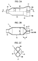
Fig. 2A is a partially cutaway sectional view of an embodiment of the Y-shaped branch pipe used in the air conditioner shown inFig. 1 . -
Fig. 2B
Fig. 2B is a sectional view taken along line a-a ofFig. 2A . -
Fig. 2C
Fig. 2C is a right side view ofFig. 2A . -
Fig. 3A
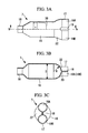
Fig. 3A is a partially cutaway sectional view of another embodiment of the Y-shaped branch pipe used in the air conditioner shown inFig. 1 . -
Fig. 3B
Fig. 3B is a sectional view taken along line b-b ofFig. 3A . -
Fig. 3C
Fig. 3C is a right side view ofFig. 3A . -
Fig. 4A
Fig. 4A is a view, equivalent to a sectional view taken along line a-a, of another embodiment of the Y-shaped branch pipe shown inFigs. 2A to 2C . -
Fig. 4B
Fig. 4B is a view, equivalent to a sectional view taken along line b-b, of another embodiment of the Y-shaped branch pipe shown inFigs. 3A to 3C . -
Fig. 5
Fig. 5 is a table showing the results of a pressure resistance test on the Y-shaped branch pipes shown inFigs. 2A to 2C andFigs. 3A to 3C . - Embodiments of the present invention will be described below with reference to the drawings.
- A first embodiment of the present invention will be described below using
Figs. 1 ,2A to 2C , and5.
Fig. 1 shows a refrigerant circuit diagram of an air conditioner using a Y-shaped branch pipe according to the present invention, andFigs. 2A to 2C show an embodiment of the Y-shaped branch pipe used in the refrigerant circuit.
An air conditioner 1 includes a compressor 2, a four-way switch valve 3, an outdoor heat exchanger 4, anoutdoor expansion valve 5, a receiver 6, a Y-shapedbranch pipe 7, a plurality ofindoor expansion valves indoor heat exchangers branch pipe 7, anaccumulator 10, and so on, which are sequentially connected viarefrigerant piping 11 to form a closed-cycle refrigerant circuit 12. The outdoor heat exchanger 4 is equipped with anoutdoor fan 13, and theindoor heat exchangers indoor fans - The Y-shaped
branch pipe 7 is installed at a branch point where a refrigerant splits into the plurality ofindoor heat exchangers refrigerant circuit 12 and, as shown inFigs. 2A to 2C , includes acylindrical pipe 15 having a pipe-connectingportion 16 formed at one end thereof, with amain line 11A on the refrigerant supply side connected thereto, and abifurcated portion 17 formed at the other end thereof, with a plurality of (two)branch lines cylindrical pipe 15 of the Y-shapedbranch pipe 7 has a wall thickness of 1.2 mm and an outer diameter of 25.4 mm, the pipe-connectingportion 16 has an inner diameter of 9.52 mm, and thebifurcated portion 17 has an inner diameter of 12.7 mm. - The
bifurcated portion 17 of the Y-shapedbranch pipe 7 is formed by pinching middle portions at the end of thecylindrical pipe 15 to bring the portions into close contact with each other, thereby forming apinch 18, and forming a pair ofchannels pinch 18, at which the portions are brought into close contact with each other. In this embodiment, L is set such that L/D = 0.3 to 0.5 is satisfied, where L is the distance between apinch base 20, formed by thepinch 18, of thebifurcated portion 17 and the cylindrical portion of thecylindrical pipe 15, and D is the outer diameter of thecylindrical pipe 15. - Because the outer diameter D of the
cylindrical pipe 15 is 25.4 mm, as described above, 0.3 to 0.5 times the outer diameter D is 7.62 to 12.7 mm; in this embodiment, the distance L is 12 mm. In this embodiment, additionally, the portion between thepinch base 20 and the cylindrical portion of thecylindrical pipe 15 has a deformedconical shape 21 that varies in shape linearly, as shown inFigs. 2A to 2C . - Furthermore, a
metal mesh strainer 30 having a cap shape that opens at one end thereof is built into thecylindrical pipe 15 to remove foreign matter from the refrigerant and to rectify the refrigerant flow reaching thebifurcated portion 17 so that the refrigerant splits evenly into the twochannels - With the configuration described above, this embodiment provides the following advantageous effects.
In the above air conditioner 1, the refrigerant supplied from the receiver 6 through themain line 11A to the Y-shapedbranch pipe 7 has foreign matter removed therefrom by thestrainer 30 in the Y-shapedbranch pipe 7 while being rectified as it passes through the metal mesh, and flows into thebifurcated portion 17, through which the refrigerant is substantially evenly split into the twochannels pinch 18. The refrigerant then flows through theindoor expansion valves indoor heat exchangers indoor fans - The Y-shaped
branch pipe 7, which is a refrigerant system component, needs to satisfy the pressure resistance strength stipulated in the relevant standards. In this embodiment, the Y-shapedbranch pipe 7 includes thepinch 18 formed by pinching middle portions at the end of thecylindrical pipe 15 to bring the portions into close contact with each other and the glasses-shapedbifurcated portion 17, formed on both sides of thepinch 18, that splits the refrigerant flow into the twochannels pinch base 20, at which the portions are brought into close contact with each other by pinching the Y-shapedbranch pipe 7, and the cylindrical portion of thecylindrical pipe 15, and D is the outer diameter of thecylindrical pipe 15. - When exposed to the internal pressure according to the pressure resistance standards, therefore, the portion between the
pinch base 20 and the cylindrical portion of thecylindrical pipe 15, if it deforms and expands into a spherical shape, experiences a smaller displacement, which avoids cracking due to stretching and thinning of thepinch base 20. It is therefore possible to provide a compact Y-shapedbranch pipe 7 that can pass a pressure resistance test according to the household electrical appliance safety regulation "IEC 60335-2-40:2002 + A1:2005 + A2:2005" of the international household electrical appliance safety standards "IEC 60335-1 Ed. 4" and therefore satisfies the pressure resistance standards. - If the distance L is set such that L/D = 0.3 to 0.5, the maximum displacement experienced by the portion between the
pinch base 20 and the cylindrical portion of thecylindrical pipe 15 as it expands into a spherical shape can be reduced to about half that for the case where L ≈ D (if the maximum displacement for the case where L ≈ D is 6.56 mm, it can be reduced to about half the displacement, namely, to 3.72 mm).Fig. 5 shows the results of a pressure resistance test on them. The results show that the burst pressure, which was 12.9 MPa before the improvement, that is, for the case where L ≈ D, increased to 19.93 MPa after the improvement, that is, for the case where L/D = 0.3 to 0.5 (specifically, the outer diameter D was 25.4 mm, the distance L was 12 mm, and L/D was about 0.47), which is about 65% higher than before the improvement, demonstrating that the burst pressure strength was four or more times the high-pressure-side design pressure for R410A refrigerants, namely, 4.15 MPa. - In addition, because the
strainer 30 is installed in the cylindrical portion of thecylindrical pipe 15, thestrainer 30 installed in the cylindrical portion rectifies the refrigerant flow so that it can be evenly split into the twochannels bifurcated portion 17. Therefore, thestrainer 30 can not only remove foreign matter from the refrigerant, but also enables the plurality ofindoor heat exchangers branch pipe 7 to exhibit equal performance. - Furthermore, because the air conditioner 1, which splits a refrigerant flow into two channels through a branch pipe, can use the Y-shaped
branch pipe 7, which is compact and satisfies the pressure resistance standards, without modification, it is possible to provide a compact air conditioner 1 that satisfies the pressure resistance standards without facing a problem such as the need to change the piping layout due to an increased branch pipe size for improved pressure resistance. - Next, a second embodiment of the present invention will be described using
Figs. 3A to 3C .
This embodiment differs from the first embodiment described above in the shape of the portion of the Y-shapedbranch pipe 7 between thepinch base 20 and the cylindrical portion of thecylindrical pipe 15. For the other points, this embodiment is similar to the first embodiment, and therefore a description thereof is omitted.
In this embodiment, as shown inFigs. 3A to 3C , the portion of the Y-shapedbranch pipe 7 between thepinch base 20 and the cylindrical portion of thecylindrical pipe 15 has aspherical shape 22 with a radius R. In this case, the radius R is 12.7 mm for thecylindrical pipe 15, which has an outer diameter D of 25.4 mm. - If the portion of the Y-shaped
branch pipe 7 between thepinch base 20 and the cylindrical portion of thecylindrical pipe 15 has thespherical shape 22 with the radius R, as above, the pressure resistance strength can be further increased as compared with the first embodiment, although that portion is slightly more difficult to form. This embodiment can therefore provide the same advantages as the first embodiment, including the ability to provide a compact Y-shapedbranch pipe 7 that can pass a pressure resistance test according to the household electrical appliance safety regulation "IEC 60335-2-40:2002 + A1:2005 + A2:2005" of the international household electrical appliance safety standards "IEC 60335-1 Ed. 4" and therefore satisfies the pressure resistance standards. - Next, a third embodiment of the present invention will be described using
Figs. 4A and 4B .
This embodiment differs from the first and second embodiments described above in that the Y-shapedbranch pipe 7 has through-holes formed in thepinch base 20. For the other points, this embodiment is similar to the first and second embodiments, and therefore a description thereof is omitted.
In this embodiment, as shown inFigs. 4A and 4B , the Y-shapedbranch pipes 7 of the first and second embodiments have through-holes 23A and 23B formed in thepinch base 20. - If the through-
holes 23A and 23B are formed in thepinch base 20, as above, when thebranch lines bifurcated portion 17, the brazing alloy overflows from inside through the through-holes 23A and 23B to formfillets 24A and 24B in the through-holes 23A and 23B, respectively. This makes it possible to determine that the brazing alloy has reached thepinch base 20 and to further improve the pressure resistance strength by joining the through-holes 23A and 23B to each other with the brazing alloy. It is therefore possible to provide a compact Y-shapedbranch pipe 7 that satisfies the pressure resistance standards and that can be easily inspected for its quality. -
Fig. 5 shows the results of a pressure resistance test on the Y-shapedbranch pipe 7, as shown in the first embodiment, to which the through-hole 23A was added (with hole; plan B). In this case, the burst pressure was 20.07 MPa, demonstrating that it increased slightly as compared with the one without the through-hole 23A (plan A). - The present invention is not limited to the invention according to the above embodiments; it can be appropriately modified without departing from the spirit thereof. For example, while the above embodiments have been illustrated with the example in which the Y-shaped
branch pipe 7 is installed at the branch point where the refrigerant splits into the plurality ofindoor heat exchangers -
- 1 air conditioner
- 7 Y-shaped branch pipe
- 15 cylindrical pipe
- 17 bifurcated portion
- 18 pinch
- 19A, 19B two channels
- 20 pinch base
- 22 spherical shape
- 23A, 23B through-hole
- 30 strainer
- D outer diameter of cylindrical pipe
- L distance between pinch base and cylindrical portion of cylindrical pipe
- R radius of spherical portion
Claims (5)
- A Y-shaped branch pipe comprising a pinch formed by pinching middle portions at an end of a cylindrical pipe to bring the portions into close contact with each other and a glasses-shaped bifurcated portion, formed on both sides of the pinch, that splits a refrigerant flow into two channels,
wherein L/D is 0.3 to 0.5, wherein L is the distance between a pinch base at which the portions are brought into close contact with each other by pinching and a cylindrical portion of the cylindrical pipe, and D is the outer diameter of the cylindrical pipe. - A Y-shaped branch pipe comprising a pinch formed by pinching middle portions at an end of a cylindrical pipe to bring the portions into close contact with each other and a glasses-shaped bifurcated portion, formed on both sides of the pinch, that splits a refrigerant flow into two channels,
wherein a portion between a pinch base at which the portions are brought into close contact with each other by pinching and a cylindrical portion of the cylindrical pipe has a spherical shape. - The Y-shaped branch pipe according to Claim 1 or 2, wherein through-holes are provided in the pinch base.
- The Y-shaped branch pipe according to one of Claims 1 to 3, wherein a strainer is installed in the cylindrical portion of the cylindrical pipe.
- An air conditioner comprising a Y-shaped branch pipe disposed at a branch point where a refrigerant flow splits into two channels in a refrigerant circuit,
wherein the Y-shaped branch pipe is the Y-shaped branch pipe according to one of Claims 1 to 4.
Applications Claiming Priority (2)
| Application Number | Priority Date | Filing Date | Title |
|---|---|---|---|
| JP2010089094A JP5619464B2 (en) | 2010-04-08 | 2010-04-08 | Y-type branch pipe and air conditioner using the same |
| PCT/JP2011/058413 WO2011125932A1 (en) | 2010-04-08 | 2011-04-01 | Y-shaped manifold and air conditioner using same |
Publications (2)
| Publication Number | Publication Date |
|---|---|
| EP2557378A1 true EP2557378A1 (en) | 2013-02-13 |
| EP2557378A4 EP2557378A4 (en) | 2013-09-18 |
Family
ID=44762870
Family Applications (1)
| Application Number | Title | Priority Date | Filing Date |
|---|---|---|---|
| EP11765832.8A Withdrawn EP2557378A4 (en) | 2010-04-08 | 2011-04-01 | Y-SHAPED COLLECTOR AND AIR CONDITIONER USING THE SAME |
Country Status (4)
| Country | Link |
|---|---|
| EP (1) | EP2557378A4 (en) |
| JP (1) | JP5619464B2 (en) |
| CN (1) | CN102667371B (en) |
| WO (1) | WO2011125932A1 (en) |
Families Citing this family (2)
| Publication number | Priority date | Publication date | Assignee | Title |
|---|---|---|---|---|
| CN104565644B (en) * | 2013-10-22 | 2017-01-18 | 珠海格力电器股份有限公司 | Stamped pipe fitting and design method thereof |
| JP2021096007A (en) * | 2019-12-13 | 2021-06-24 | パナソニックIpマネジメント株式会社 | Branch pipes, branching equipment, heat exchangers and refrigerating equipment |
Family Cites Families (11)
| Publication number | Priority date | Publication date | Assignee | Title |
|---|---|---|---|---|
| JPS57171189A (en) * | 1981-04-13 | 1982-10-21 | Mitsubishi Heavy Ind Ltd | Y-shaped manifold |
| JP2813272B2 (en) * | 1992-07-30 | 1998-10-22 | シャープ株式会社 | Refrigerant flow divider |
| JPH10300277A (en) * | 1997-05-01 | 1998-11-13 | Gou Shoji Kk | Branch pipe for refrigerant |
| JPH10339521A (en) * | 1997-06-10 | 1998-12-22 | Gou Shoji Kk | Branching pipe for refrigerant |
| JP3606732B2 (en) | 1997-07-04 | 2005-01-05 | ユニオン空調工業株式会社 | Branch joint for refrigerant pipe |
| JPH11125379A (en) * | 1997-10-20 | 1999-05-11 | Mitsubishi Electric Corp | Air conditioner |
| JPH11304297A (en) * | 1998-04-23 | 1999-11-05 | Aisin Seiki Co Ltd | Refrigerant branching device |
| JP2006266563A (en) * | 2005-03-23 | 2006-10-05 | Matsushita Electric Ind Co Ltd | Air conditioner |
| JP2007032921A (en) * | 2005-07-26 | 2007-02-08 | Kakinuma Kinzoku Seiki Kk | Flow divider and its manufacturing method |
| JP2007064489A (en) * | 2005-08-29 | 2007-03-15 | Sanyo Electric Co Ltd | Air conditioner |
| CN201074930Y (en) * | 2007-09-05 | 2008-06-18 | 海信(山东)空调有限公司 | Air conditioner separator and indoor set of air-conditioner using the same |
-
2010
- 2010-04-08 JP JP2010089094A patent/JP5619464B2/en active Active
-
2011
- 2011-04-01 CN CN201180005103.1A patent/CN102667371B/en active Active
- 2011-04-01 WO PCT/JP2011/058413 patent/WO2011125932A1/en not_active Ceased
- 2011-04-01 EP EP11765832.8A patent/EP2557378A4/en not_active Withdrawn
Non-Patent Citations (2)
| Title |
|---|
| No further relevant documents disclosed * |
| See also references of WO2011125932A1 * |
Also Published As
| Publication number | Publication date |
|---|---|
| JP2011220592A (en) | 2011-11-04 |
| CN102667371A (en) | 2012-09-12 |
| WO2011125932A1 (en) | 2011-10-13 |
| CN102667371B (en) | 2017-05-10 |
| EP2557378A4 (en) | 2013-09-18 |
| JP5619464B2 (en) | 2014-11-05 |
Similar Documents
| Publication | Publication Date | Title |
|---|---|---|
| EP2423609B1 (en) | Heat exchanger and air conditioner on which this heat exchanger is mounted | |
| CN101268312B (en) | air conditioner | |
| US12055328B2 (en) | Refrigeration apparatus and refrigerant pipe of the same refrigeration apparatus | |
| AU2022267168B2 (en) | Pipe Coupling Structure and Refrigeration Cycle Apparatus | |
| US20180320977A1 (en) | Heat exchanger, air-conditioning apparatus including the same, and method of producing flat-tube u-bend | |
| WO2007013439A1 (en) | Heat exchanger | |
| EP1978315A3 (en) | Outdoor Unit for Multi-Air Conditioner | |
| EP1947405A1 (en) | Air conditioner | |
| JP7436789B2 (en) | Plate type refrigerant piping and refrigeration equipment | |
| CN102667371B (en) | Y-shaped manifold and air conditioner using same | |
| GB2508842A (en) | Double wall tube heat exchanger | |
| US20230082318A1 (en) | Pressure vessel and refrigeration apparatus | |
| US20220146159A1 (en) | Refrigeration apparatus | |
| CN211926198U (en) | Heat exchanger and air conditioner | |
| KR20120005558U (en) | Connecting pipe of multi air conditioner | |
| CN214949434U (en) | Air conditioner host and indoor unit quick connection structure | |
| CN220541327U (en) | Integrated structure pipeline piece | |
| CN212179281U (en) | Condenser, air-conditioning system, and pipe joints | |
| KR200326219Y1 (en) | Structure of refrigerants pipe for multi air-conditioner | |
| CN116804475A (en) | Air conditioner and compression type refrigerating system thereof | |
| CN116951840A (en) | Integrated structure pipeline piece and processing method thereof | |
| CN115218016A (en) | Air conditioner cut-off valve and air conditioner | |
| CN117308207A (en) | Heat exchanger and air conditioning unit | |
| JP2021096007A (en) | Branch pipes, branching equipment, heat exchangers and refrigerating equipment | |
| JPS60211278A (en) | Adapter for connecting refrigerant piping |
Legal Events
| Date | Code | Title | Description |
|---|---|---|---|
| PUAI | Public reference made under article 153(3) epc to a published international application that has entered the european phase |
Free format text: ORIGINAL CODE: 0009012 |
|
| 17P | Request for examination filed |
Effective date: 20120625 |
|
| AK | Designated contracting states |
Kind code of ref document: A1 Designated state(s): AL AT BE BG CH CY CZ DE DK EE ES FI FR GB GR HR HU IE IS IT LI LT LU LV MC MK MT NL NO PL PT RO RS SE SI SK SM TR |
|
| DAX | Request for extension of the european patent (deleted) | ||
| A4 | Supplementary search report drawn up and despatched |
Effective date: 20130819 |
|
| RIC1 | Information provided on ipc code assigned before grant |
Ipc: F25B 41/00 20060101AFI20130812BHEP Ipc: F25B 43/00 20060101ALI20130812BHEP |
|
| STAA | Information on the status of an ep patent application or granted ep patent |
Free format text: STATUS: EXAMINATION IS IN PROGRESS |
|
| 17Q | First examination report despatched |
Effective date: 20170526 |
|
| RAP1 | Party data changed (applicant data changed or rights of an application transferred) |
Owner name: MITSUBISHI HEAVY INDUSTRIES THERMAL SYSTEMS, LTD. |
|
| GRAP | Despatch of communication of intention to grant a patent |
Free format text: ORIGINAL CODE: EPIDOSNIGR1 |
|
| STAA | Information on the status of an ep patent application or granted ep patent |
Free format text: STATUS: GRANT OF PATENT IS INTENDED |
|
| INTG | Intention to grant announced |
Effective date: 20190423 |
|
| STAA | Information on the status of an ep patent application or granted ep patent |
Free format text: STATUS: THE APPLICATION IS DEEMED TO BE WITHDRAWN |
|
| 18D | Application deemed to be withdrawn |
Effective date: 20190904 |