EP2557296A2 - System and method for hot ambient and grid frequency compensation for a gas turbine - Google Patents
System and method for hot ambient and grid frequency compensation for a gas turbine Download PDFInfo
- Publication number
- EP2557296A2 EP2557296A2 EP12178848A EP12178848A EP2557296A2 EP 2557296 A2 EP2557296 A2 EP 2557296A2 EP 12178848 A EP12178848 A EP 12178848A EP 12178848 A EP12178848 A EP 12178848A EP 2557296 A2 EP2557296 A2 EP 2557296A2
- Authority
- EP
- European Patent Office
- Prior art keywords
- variable blade
- compressor
- gas turbine
- airflow
- blade rows
- Prior art date
- Legal status (The legal status is an assumption and is not a legal conclusion. Google has not performed a legal analysis and makes no representation as to the accuracy of the status listed.)
- Granted
Links
Images


Classifications
-
- F—MECHANICAL ENGINEERING; LIGHTING; HEATING; WEAPONS; BLASTING
- F02—COMBUSTION ENGINES; HOT-GAS OR COMBUSTION-PRODUCT ENGINE PLANTS
- F02C—GAS-TURBINE PLANTS; AIR INTAKES FOR JET-PROPULSION PLANTS; CONTROLLING FUEL SUPPLY IN AIR-BREATHING JET-PROPULSION PLANTS
- F02C7/00—Features, components parts, details or accessories, not provided for in, or of interest apart form groups F02C1/00 - F02C6/00; Air intakes for jet-propulsion plants
- F02C7/04—Air intakes for gas-turbine plants or jet-propulsion plants
- F02C7/057—Control or regulation
-
- F—MECHANICAL ENGINEERING; LIGHTING; HEATING; WEAPONS; BLASTING
- F01—MACHINES OR ENGINES IN GENERAL; ENGINE PLANTS IN GENERAL; STEAM ENGINES
- F01D—NON-POSITIVE DISPLACEMENT MACHINES OR ENGINES, e.g. STEAM TURBINES
- F01D17/00—Regulating or controlling by varying flow
- F01D17/10—Final actuators
- F01D17/12—Final actuators arranged in stator parts
- F01D17/14—Final actuators arranged in stator parts varying effective cross-sectional area of nozzles or guide conduits
- F01D17/16—Final actuators arranged in stator parts varying effective cross-sectional area of nozzles or guide conduits by means of nozzle vanes
- F01D17/162—Final actuators arranged in stator parts varying effective cross-sectional area of nozzles or guide conduits by means of nozzle vanes for axial flow, i.e. the vanes turning around axes which are essentially perpendicular to the rotor centre line
-
- F—MECHANICAL ENGINEERING; LIGHTING; HEATING; WEAPONS; BLASTING
- F05—INDEXING SCHEMES RELATING TO ENGINES OR PUMPS IN VARIOUS SUBCLASSES OF CLASSES F01-F04
- F05D—INDEXING SCHEME FOR ASPECTS RELATING TO NON-POSITIVE-DISPLACEMENT MACHINES OR ENGINES, GAS-TURBINES OR JET-PROPULSION PLANTS
- F05D2270/00—Control
- F05D2270/01—Purpose of the control system
- F05D2270/02—Purpose of the control system to control rotational speed (n)
-
- F—MECHANICAL ENGINEERING; LIGHTING; HEATING; WEAPONS; BLASTING
- F05—INDEXING SCHEMES RELATING TO ENGINES OR PUMPS IN VARIOUS SUBCLASSES OF CLASSES F01-F04
- F05D—INDEXING SCHEME FOR ASPECTS RELATING TO NON-POSITIVE-DISPLACEMENT MACHINES OR ENGINES, GAS-TURBINES OR JET-PROPULSION PLANTS
- F05D2270/00—Control
- F05D2270/01—Purpose of the control system
- F05D2270/05—Purpose of the control system to affect the output of the engine
- F05D2270/053—Explicitly mentioned power
Definitions
- the present disclosure relates generally to gas turbines, and more particularly to a system and method for flexible control and operation of a gas turbine.
- a gas turbine typically includes a compressor located at the front, one or more combustors around the middle, and a turbine at the rear.
- the compressor can include multiple stages of compressor blades attached to a rotor. Ambient air, as a working fluid, enters an inlet of the compressor, and rotation of the compressor blades progressively compresses the working fluid.
- the compressor can include one or more variable blade rows, such as inlet guide vanes (IGVs) and variable stator vanes (VSVs), which can be used to control the flow of ambient air into the compressor.
- IGVs inlet guide vanes
- VSVs variable stator vanes
- Some of the compressed working fluid is extracted from the compressor through extraction ports for other use, and the remainder of the working fluid exits the compressor and flows to the combustors.
- the working fluid mixes with fuel in the combustors, and the mixture ignites to generate combustion gases having a high temperature, pressure, and velocity.
- the combustion gases exit the combustors and flow to the turbine where they expand to produce work.
- Electricity demand typically increases with increases in ambient temperature. Maximizing output of gas turbines at times with increased ambient temperatures is advantageous because of commercial opportunities for significant revenue generation as electricity demand and prices escalate with the ambient temperature.
- the capacity to supply electricity with gas turbines generally decreases as the ambient temperature increases. This is due to the negative influence of increased ambient temperature on density and airflow capacity of the turbine.
- increased ambient temperature provides for increased economic opportunity with reduced capacity to fulfill energy demands.
- Power generation revenues can also be enhanced by providing electrical power grid frequency stabilization services. For instance, if demand exceeds capacity-due to, for example, too many HVAC units running, the electrical grid can experience an "under-frequency" event.
- the need for frequency stabilization services has increased due to the rising contribution of renewable sources of energy connected to the grid.
- intermittent sources of energy such as wind turbines and solar panels, can contribute to a transient excess of power applied to the grid, resulting in an "over-frequency" event.
- a wind turbine can provide a transient excess of power to the grid due to an increase in wind at the wind turbine site.
- a photovoltaic array can provide a transient excess of power to the grid as the sun comes out and solar rays are incident on the photovoltaic array.
- Gas turbines can be operated to provide frequency stabilization services by providing more or less output power to the grid. For instance, gas turbines can be operated to output more power to the grid in response to an under-frequency event. Alternatively, gas turbines can be operated to output less power to the grid in response to an over-frequency event.
- the rotational speed of gas turbines is not a parameter that can be adjusted to provide frequency stabilization for the grid.
- the rotational speed of the gas turbines is synchronized to the frequency of the grid. For instance, the nominal rotational speed for 50 Hz grids is about 3000 RPM, and for 60 Hz grids is about 3600 RPM.
- the output power of gas turbines is typically increased using techniques such as wet compression, automatic over-firing, and adjustment of variable blade rows according to variable blade row schedules that compensate for flow needs without user select-ability. These techniques do not typically provide the user the flexibility to control the output of the gas turbine to provide optimum output for revenue generation.
- a system and method that can reduce the effects of increased ambient temperature on gas turbine output would be particularly useful.
- One exemplary embodiment of the present disclosure is directed to a method for controlling the output power of a gas turbine.
- the method includes supplying compressed working fluid from a compressor for use with the gas turbine.
- the compressor is oversized in airflow capacity.
- the method further includes providing airflow through one or more variable blade rows into the compressor and receiving a request to operate the gas turbine system in a nominal mode, a controlled output mode or in a frequency compensation mode.
- the method includes controlling the position of the one or more variable blade rows in accordance with a predetermined nominal variable blade row position schedule.
- the method includes adjusting the position of the one or more variable blade rows from the nominal positions set forth in the nominal variable blade row position schedule to operate the gas turbine in the controlled output mode or in the frequency compensation mode.
- the gas turbine system includes a compressor oversized in airflow capacity configured to supply compressed air for use during combustion in the gas turbine and one or more variable blade rows configured to control the airflow rate into the compressor.
- the variable blade rows are movable between a first position where the one or more variable blade rows provide a maximum airflow rate into the compressor and a second position where the one or more variable blade rows provide a reduced airflow rate into the compressor.
- the system further includes a controller configured to control the position of the one or more variable blade rows according to a nominal variable blade row position schedule.
- the nominal variable blade row position schedule specifies nominal positions for the one or more variable blade rows such that the one or more variable blade rows provide a nominal airflow rate into the compressor.
- the nominal airflow rate is less than the maximum airflow rate into the compressor.
- the controller is configured to adjust the position of the one or more variable blade rows from the nominal positions specified in the nominal variable blade row schedule to operate the gas turbine system in the controlled output mode or in the frequency compensation mode.
- a further exemplary embodiment of the present disclosure is directed to a gas turbine system operable in a nominal mode, a controlled output mode and in a frequency compensation mode.
- the gas turbine system includes a compressor oversized in airflow capacity configured to supply compressed air for use in combustion in the gas turbine and one or more variable blade rows for controlling the airflow into the compressor.
- the gas turbine system further includes a controller configured to control the position of the one or variable blade rows according to a nominal variable blade row schedule when the gas turbine system is operated in the nominal mode.
- the controller is further configured to adjust the position of the one or more variable blade rows from the nominal positions set forth in the nominal variable blade row schedule in response to a request to operate the gas turbine in the controlled output mode or the frequency compensation mode.
- the controller When the gas turbine system is operated in the controlled output mode, the controller is configured to adjust the position of the one or more variable blade rows to increase or decrease airflow into the compressor to achieve a power output requested by an operator.
- the controller When the gas turbine system is operated in the frequency compensation mode, the controller is configured to monitor the frequency of an electricity grid and adjust the position of the one or more variable blade rows based at least in part on the frequency of the electricity grid.
- the present disclosure is directed to systems and methods for hot ambient and frequency compensation for a gas turbine.
- three modes of controlling a gas turbine are provided for the purpose of either operating the gas turbine system according to a nominal schedule, controlling output for the maximization of revenue generation, or for providing an ancillary service of frequency regulation-an alternative method for revenue generation.
- a compressor oversized in airflow capacity
- a compressed working fluid such as air
- a gas turbine a compressed working fluid
- VBRs variable blade rows
- IGVs and VSVs associated with the compressor are closed sufficiently to throttle the flow rate of the compressor down to a desired level.
- a nominal variable blade row schedule is defined consistent with the variable blade rows throttled down to provide the desired design point level of flow.
- An operator can request to operate the turbine in a nominal mode, a controlled output mode, or in a frequency compensation mode.
- the controller controls the position of the variable blade rows in accordance with the nominal variable blade row schedule.
- the operator Pursuant to a request to operate the gas turbine in the controlled output mode, the operator will have the ability to request that the gas turbine operate to provide a desired output, such as an increased output.
- the controller will adjust the position of the variable blade rows from the positions specified in the nominal variable blade row schedule to provide the power output requested by the operator.
- the controller for the gas turbine system monitors the frequency of the electrical grid.
- the controller is configured to modulate the variable blade rows based on the frequency of the electrical grid. For instance, the controller is configured to open the variable blade rows from their nominal position to induce greater airflow and thus provide more power during an under-frequency condition.
- the controller is configured to close the variable blade rows from their nominal position to induce reduced airflow and thus provide reduced power during an over-frequency condition.
- variable blade row modulation in the frequency compensation mode is expected to be more frequent but smaller in amplitude. Controlling the turbine output through modulation of the variable blade rows when compared to over-firing of the gas turbine provides for reduction of life consumption of hot parts, decreasing maintenance costs.
- the gas turbine systems and methods of the present disclosure will have increased marketability by providing an operator the flexibility in determining whether to maximize power generation revenue, for instance, during times with increased ambient temperature or to provide the ancillary service of frequency stabilization.
- the gas turbine systems and methods of the present disclosure also provide advantages over known gas turbine systems by providing better performance during times with increased ambient temperatures.
- the frequency compensation mode also provides advantages in market segments and/or regions heavily influenced by renewable energy sources, such as wind energy sources or solar energy sources.
- FIG. 1 provides a block diagram of an exemplary gas turbine system 100 according to an exemplary embodiment of the present disclosure.
- Gas turbine system 100 includes a compressor 110, a combustor, 114, a turbine 120, and a generator 130.
- Compressor 110 is configured to provide a compressed working fluid for use in combustor 114.
- the compressed working fluid mixes with fuel in the gas turbine combustor 114, and the mixture ignites to generate combustion gases having a high temperature, pressure, and velocity.
- the combustion gases expand in the turbine section 120 to produce work to turn rotatable shaft 112.
- the rotatable shaft 112 of the drives the generator 130 which in turns generates electrical power.
- Generator 130 provides the electrical power to the electricity grid.
- Compressor 110 includes a plurality of variable blade rows 140, such as inlet guide vanes (IGVs) and variable stator vanes (VSVs) that control the inlet air flow into the compressor 110.
- the variable blade rows 140 are movable between a first and open position where the variable blade rows 140 provide for a maximum airflow rate into the compressor 110 and a second and closed position where the variable blade rows 140 provide for a reduced airflow rate into the compressor 110.
- the output power of the gas turbine system 100 can be controlled by adjusting the airflow rate into the compressor 110. For instance, higher output can be achieved by opening the variable blade rows 140 to provide increased airflow into the compressor 110. Similarly, lower output can be achieved by closing or throttling down the variable blade rows 140 to provide decreased airflow into the compressor 110.
- Gas turbine system 100 includes a controller 150 that controls, among other parameters of the gas turbine system 100, the position of the variable blade rows 140.
- the controller 150 receives a signal indicative of the position of the variable blade rows 140.
- the controller 150 continuously generates a difference signal between the detected variable blade row position and a desired variable blade row position to generate an error signal.
- the controller 150 adjusts the position of the variable blade rows 140 based on the error signal such that the actual variable blade row position is maintained close to the desired variable blade row position.
- compressor 110 is oversized in airflow capacity such that the compressor 110 can provide an increased airflow rate when compared to its nominal or design flow rate.
- the design cycle of a typical compressor for use with a gas turbine is typically concluded by the experimental mapping of various parameters including an aerodynamic design point for the compressor.
- Compressors are typically designed to provide an optimum design point airflow rate through the compressor at a particular design point ambient temperature.
- the design point airflow rate provides for optimum performance of the compressor at the design point ambient temperature.
- a compressor may be designed to have a particular optimum design point airflow rate through the compressor at an ambient temperature of 59 °F. This temperature is arbitrary, but typically known as the ISO standard day temperature.
- the compressor 110 is oversized in airflow capacity such that the compressor 110 provides an increased airflow rate at the design point temperature relative to the design point airflow rate.
- the compressor 110 can be oversized in airflow capacity such that the compressor 110 provides an airflow rate that is approximately 5% to 25%, such as about 15%, greater than the design point airflow rate at 59 °F. In this manner, the compressor 110 can accommodate increased airflow rates relative to typical compressors to compensate for density loss during times with increased ambient temperatures.
- variable blade rows 140 can be used to throttle down the compressor 110 so that it operates at the desired optimum airflow rate at the design point temperature.
- controller 150 can control the position of the variable blade rows 140 in accordance with a predetermined nominal variable blade row position schedule.
- the nominal variable blade row position schedule can specify nominal variable blade row positions such that the variable blade rows provide nominal airflow rates into the compressor 110.
- the nominal airflow rates into the compressor are preferably less than the maximum airflow rates into the compressor 110 so that the compressor 110 operates closer to the design point level of flow at the design point ambient temperature.
- the gas turbine system 100 can be operated, pursuant to a request, in either the nominal mode, a controlled output mode, or in a frequency compensation mode.
- the controller 150 adjusts the position of the variable blade rows 140 from the positions specified in the nominal variable blade row position schedule to achieve a desired gas turbine output or to provide frequency compensation services.
- controller 150 is configured to adjust the position of the variable blade rows 140 from the nominal position specified in the nominal variable blade row position schedule to increase or decrease the output of the gas turbine system 100.
- Modulation of the variable blade rows 140 during the controlled output mode is relatively deliberate and can be done in response to a request to provide more or less output.
- the natural decrease in airflow capacity observed with increased ambient temperatures can be offset by opening the variable blade rows 140 from the nominal position set forth in the nominal variable blade row schedule.
- the variable blade rows 140 can be closed from the nominal position set forth in the nominal variable blade row schedule in circumstances where, for instance, there are more economical power generation assets available and there is a need to keep the gas turbine synchronized to the grid.
- Curve 210 represents the airflow of compressor operating pursuant in the nominal mode. As illustrated, density lapse occurs in the compressor with increased ambient temperatures, causing the airflow capacity, and thus output, of the compressor to decrease with ambient temperature.
- Curve 220 represents the airflow capacity of the compressor being operated in the controlled output mode. As indicated by curve 220, as the variable blade rows open from the positions set forth in the nominal variable blade row schedule, the reduction in airflow due to density lapse in the compressor is reduced until the variable blade rows are fully open at point 222. Once the variable blade rows are fully open, the compressor 110 will experience reduced airflow capacity as ambient temperature increases. As illustrated in FIG. 2 , when the gas turbine system 100 is operated in the controlled output mode, the decrease in output associated with increased ambient temperatures can be offset by opening the variable blade rows 140 from their nominal positions.
- the controller 150 for the gas turbine system 100 monitors the grid frequency of the electricity grid.
- the controller 150 is configured to adjust the variable blade rows 140 from the nominal position specified in the nominal variable blade row position schedule to induce greater airflow and provide more power during an under-frequency condition and to induce reduced airflow and reduced power during an over-frequency condition.
- a deadband can be specified where no variable blade row modulation occurs in the frequency compensation mode to prevent unnecessary dithering of the variable blade rows 140.
- the deadband can include a first threshold and a second threshold.
- the controller can be configured to adjust the position of the one or more variable blade rows to provide increased airflow into said compressor when the frequency of the electricity grid is less than the first threshold; adjust the position the one or more variable blade rows to provide decreased airflow into said compressor when the frequency of the electricity grid is greater than the second threshold; and maintain the position of the one or more variable blade rows when the frequency of the electricity grid is greater than or approximately equal to the first threshold and less than or approximately equal to the second threshold.
- Curve 230 illustrates the modulation of the variable blade rows in response to under- and over- frequency events.
- the controller 150 is configured to adjust the variable blade rows 140, and thus airflow into the compressor 110, from the nominal positions specified in the nominal variable blade row position schedule such that the gas turbine system 100 provides frequency compensation services.
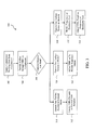
- FIG. 3 illustrates a flow diagram of an exemplary method 300 according to an exemplary embodiment of the present disclosure.
- the method 300 includes supplying compressed air from a compressor for use in combustion in a gas turbine.
- the compressor can be oversized in airflow capacity such that the compressor can provide an increased airflow rate at a design point ambient temperature that is greater than the design point airflow rate at the design point ambient temperature.
- the compressor can be oversized in airflow capacity such that the increased airflow rate at 59 °F is approximately 5% to 25%, such as about 15%, greater than the design point airflow rate at 59 °F.
- the method 300 provides airflow through variable blade rows to the compressor.
- an operator can request to operate the gas turbine system in either a nominal mode, a controlled output mode, or a frequency compensation mode.
- the operator can set the mode of operation during turbine startup or during any other time during operation of the gas turbine.
- the gas turbine 310 in response to a request to operate the gas turbine in a nominal mode, the gas turbine 310 is operated in the nominal mode.
- the position of the variable blade rows can be controlled by a controller pursuant to a nominal variable blade row schedule as indicated at 312.
- the nominal variable blade row schedule can specify nominal positions for the variable blade rows such that the variable blade rows provide a nominal airflow rate into the compressor, typically as a function of ambient temperature.
- the nominal airflow rate can be a throttled down airflow rate such that the variable blade rows can be opened from the nominal positions to compensate for increased ambient temperature or under-frequency conditions as desired.
- the method 300 will operate the gas turbine system in the controlled output mode as indicated at 320.
- the method 300 at 354 includes adjusting the position of the variable blade rows from the nominal positions set forth in the nominal variable blade row schedule to provide a power output request by the operator. For instance, as discussed above, the method 300 can open the variable blade rows from their nominal position to increase airflow into the compressor to compensate for airflow loss in the compressor due to increased ambient temperature.
- the method 300 will operate the gas turbine system in the frequency compensation mode as indicated at 330.
- the method 300 includes monitoring the frequency of the electricity grid as shown at 332 and adjusting the position of the variable blade rows from the nominal positions specified in the nominal variable blade row schedule based at least in part on the grid frequency as indicated at 334. For instance, as discussed above, the method 300 can adjust the variable blade rows from the nominal positions specified in the nominal variable blade row position schedule to induce greater airflow and provide more power during an under-frequency condition and to induce reduced airflow and reduced power during an over-frequency condition.
Landscapes
- Engineering & Computer Science (AREA)
- Chemical & Material Sciences (AREA)
- Combustion & Propulsion (AREA)
- Mechanical Engineering (AREA)
- General Engineering & Computer Science (AREA)
- Control Of Positive-Displacement Air Blowers (AREA)
- Structures Of Non-Positive Displacement Pumps (AREA)
Abstract
Description
- The present disclosure relates generally to gas turbines, and more particularly to a system and method for flexible control and operation of a gas turbine.
- Gas turbines are widely used in commercial operations for power generation. A gas turbine typically includes a compressor located at the front, one or more combustors around the middle, and a turbine at the rear. The compressor can include multiple stages of compressor blades attached to a rotor. Ambient air, as a working fluid, enters an inlet of the compressor, and rotation of the compressor blades progressively compresses the working fluid. The compressor can include one or more variable blade rows, such as inlet guide vanes (IGVs) and variable stator vanes (VSVs), which can be used to control the flow of ambient air into the compressor.
- Some of the compressed working fluid is extracted from the compressor through extraction ports for other use, and the remainder of the working fluid exits the compressor and flows to the combustors. The working fluid mixes with fuel in the combustors, and the mixture ignites to generate combustion gases having a high temperature, pressure, and velocity. The combustion gases exit the combustors and flow to the turbine where they expand to produce work.
- Electricity demand typically increases with increases in ambient temperature. Maximizing output of gas turbines at times with increased ambient temperatures is advantageous because of commercial opportunities for significant revenue generation as electricity demand and prices escalate with the ambient temperature. However, the capacity to supply electricity with gas turbines generally decreases as the ambient temperature increases. This is due to the negative influence of increased ambient temperature on density and airflow capacity of the turbine. Thus, for typical gas turbines, increased ambient temperature provides for increased economic opportunity with reduced capacity to fulfill energy demands.
- Power generation revenues can also be enhanced by providing electrical power grid frequency stabilization services. For instance, if demand exceeds capacity-due to, for example, too many HVAC units running, the electrical grid can experience an "under-frequency" event. The need for frequency stabilization services has increased due to the rising contribution of renewable sources of energy connected to the grid. In particular, intermittent sources of energy, such as wind turbines and solar panels, can contribute to a transient excess of power applied to the grid, resulting in an "over-frequency" event. For instance, a wind turbine can provide a transient excess of power to the grid due to an increase in wind at the wind turbine site. A photovoltaic array can provide a transient excess of power to the grid as the sun comes out and solar rays are incident on the photovoltaic array. Such transient excess supplies of power can result in over-frequency events. Conversely, as renewable sources of power diminish due to, for instance, low wind speeds or on a cloudy day, an "under-frequency" event can occur, particularly in situations where generation demand exceeds the capacity of assets connected to the grid.
- Gas turbines can be operated to provide frequency stabilization services by providing more or less output power to the grid. For instance, gas turbines can be operated to output more power to the grid in response to an under-frequency event. Alternatively, gas turbines can be operated to output less power to the grid in response to an over-frequency event.
- The rotational speed of gas turbines is not a parameter that can be adjusted to provide frequency stabilization for the grid. The rotational speed of the gas turbines is synchronized to the frequency of the grid. For instance, the nominal rotational speed for 50 Hz grids is about 3000 RPM, and for 60 Hz grids is about 3600 RPM. To provide frequency stabilization, the output power of gas turbines is typically increased using techniques such as wet compression, automatic over-firing, and adjustment of variable blade rows according to variable blade row schedules that compensate for flow needs without user select-ability. These techniques do not typically provide the user the flexibility to control the output of the gas turbine to provide optimum output for revenue generation.
- Thus, a need exists for a system and method that provides flexibility to an operator to control the gas turbine to provide enhanced output for increased revenue generation, or alternatively, to operate the gas turbine to provide frequency stabilization services. A system and method that can reduce the effects of increased ambient temperature on gas turbine output would be particularly useful.
- Aspects and advantages of the invention will be set forth in part in the following description, or may be obvious from the description, or may be learned through practice of the invention.
- One exemplary embodiment of the present disclosure is directed to a method for controlling the output power of a gas turbine. The method includes supplying compressed working fluid from a compressor for use with the gas turbine. The compressor is oversized in airflow capacity. The method further includes providing airflow through one or more variable blade rows into the compressor and receiving a request to operate the gas turbine system in a nominal mode, a controlled output mode or in a frequency compensation mode. When the gas turbine is operated in the nominal mode, the method includes controlling the position of the one or more variable blade rows in accordance with a predetermined nominal variable blade row position schedule. The method includes adjusting the position of the one or more variable blade rows from the nominal positions set forth in the nominal variable blade row position schedule to operate the gas turbine in the controlled output mode or in the frequency compensation mode.
- Another exemplary embodiment of the present disclosure is directed to a gas turbine system. The gas turbine system includes a compressor oversized in airflow capacity configured to supply compressed air for use during combustion in the gas turbine and one or more variable blade rows configured to control the airflow rate into the compressor. The variable blade rows are movable between a first position where the one or more variable blade rows provide a maximum airflow rate into the compressor and a second position where the one or more variable blade rows provide a reduced airflow rate into the compressor. The system further includes a controller configured to control the position of the one or more variable blade rows according to a nominal variable blade row position schedule. The nominal variable blade row position schedule specifies nominal positions for the one or more variable blade rows such that the one or more variable blade rows provide a nominal airflow rate into the compressor. The nominal airflow rate is less than the maximum airflow rate into the compressor. Pursuant to a request the gas turbine system in either a controlled output mode or a frequency compensation mode, the controller is configured to adjust the position of the one or more variable blade rows from the nominal positions specified in the nominal variable blade row schedule to operate the gas turbine system in the controlled output mode or in the frequency compensation mode.
- A further exemplary embodiment of the present disclosure is directed to a gas turbine system operable in a nominal mode, a controlled output mode and in a frequency compensation mode. The gas turbine system includes a compressor oversized in airflow capacity configured to supply compressed air for use in combustion in the gas turbine and one or more variable blade rows for controlling the airflow into the compressor. The gas turbine system further includes a controller configured to control the position of the one or variable blade rows according to a nominal variable blade row schedule when the gas turbine system is operated in the nominal mode. The controller is further configured to adjust the position of the one or more variable blade rows from the nominal positions set forth in the nominal variable blade row schedule in response to a request to operate the gas turbine in the controlled output mode or the frequency compensation mode. When the gas turbine system is operated in the controlled output mode, the controller is configured to adjust the position of the one or more variable blade rows to increase or decrease airflow into the compressor to achieve a power output requested by an operator. When the gas turbine system is operated in the frequency compensation mode, the controller is configured to monitor the frequency of an electricity grid and adjust the position of the one or more variable blade rows based at least in part on the frequency of the electricity grid.
- These and other features, aspects and advantages of the present invention will become better understood with reference to the following description and appended claims. The accompanying drawings, which are incorporated in and constitute a part of this specification, illustrate embodiments of the invention and, together with the description, serve to explain the principles of the invention.
- A full and enabling disclosure of the present invention, including the best mode thereof, directed to one of ordinary skill in the art, is set forth in the specification, which makes reference to the appended figures, in which:
-
FIG. 1 provides a block diagram of an exemplary gas turbine according to an exemplary embodiment of the present disclosure; -
FIG. 2 provides a graphical representation of compressor airflow vs. ambient temperature for a gas turbine system operating in the controlled output mode (Mode I) and the frequency compensation mode (Mode II) according to an exemplary embodiment of the present disclosure; and -
FIG. 3 provides a flow diagram of an exemplary method according to an exemplary embodiment of the present disclosure. - Reference now will be made in detail to embodiments of the invention, one or more examples of which are illustrated in the drawings. Each example is provided by way of explanation of the invention, not limitation of the invention. In fact, it will be apparent to those skilled in the art that various modifications and variations can be made in the present invention without departing from the scope or spirit of the invention. For instance, features illustrated or described as part of one embodiment can be used with another embodiment to yield a still further embodiment. Thus, it is intended that the present invention covers such modifications and variations as come within the scope of the appended claims and their equivalents.
- Generally, the present disclosure is directed to systems and methods for hot ambient and frequency compensation for a gas turbine. According to aspects of the present disclosure, three modes of controlling a gas turbine are provided for the purpose of either operating the gas turbine system according to a nominal schedule, controlling output for the maximization of revenue generation, or for providing an ancillary service of frequency regulation-an alternative method for revenue generation.
- According to particular aspects of the present disclosure, a compressor, oversized in airflow capacity, is used to provide a compressed working fluid, such as air, for combustion in a gas turbine. To provide a desired, design point airflow rate with the oversized compressor, variable blade rows (VBRs), such as IGVs and VSVs, associated with the compressor are closed sufficiently to throttle the flow rate of the compressor down to a desired level. A nominal variable blade row schedule is defined consistent with the variable blade rows throttled down to provide the desired design point level of flow.
- An operator can request to operate the turbine in a nominal mode, a controlled output mode, or in a frequency compensation mode. Pursuant to an a request to operate the turbine in a nominal mode, the controller controls the position of the variable blade rows in accordance with the nominal variable blade row schedule.
- Pursuant to a request to operate the gas turbine in the controlled output mode, the operator will have the ability to request that the gas turbine operate to provide a desired output, such as an increased output. The controller will adjust the position of the variable blade rows from the positions specified in the nominal variable blade row schedule to provide the power output requested by the operator.
- Pursuant to a request to operate the gas turbine in the frequency compensation mode the controller for the gas turbine system monitors the frequency of the electrical grid. The controller is configured to modulate the variable blade rows based on the frequency of the electrical grid. For instance, the controller is configured to open the variable blade rows from their nominal position to induce greater airflow and thus provide more power during an under-frequency condition. The controller is configured to close the variable blade rows from their nominal position to induce reduced airflow and thus provide reduced power during an over-frequency condition. Relative to controlled output mode, variable blade row modulation in the frequency compensation mode is expected to be more frequent but smaller in amplitude. Controlling the turbine output through modulation of the variable blade rows when compared to over-firing of the gas turbine provides for reduction of life consumption of hot parts, decreasing maintenance costs.
- The gas turbine systems and methods of the present disclosure will have increased marketability by providing an operator the flexibility in determining whether to maximize power generation revenue, for instance, during times with increased ambient temperature or to provide the ancillary service of frequency stabilization. The gas turbine systems and methods of the present disclosure also provide advantages over known gas turbine systems by providing better performance during times with increased ambient temperatures. The frequency compensation mode also provides advantages in market segments and/or regions heavily influenced by renewable energy sources, such as wind energy sources or solar energy sources.
-
FIG. 1 provides a block diagram of an exemplarygas turbine system 100 according to an exemplary embodiment of the present disclosure.Gas turbine system 100 includes acompressor 110, a combustor, 114, aturbine 120, and agenerator 130.Compressor 110 is configured to provide a compressed working fluid for use incombustor 114. The compressed working fluid mixes with fuel in thegas turbine combustor 114, and the mixture ignites to generate combustion gases having a high temperature, pressure, and velocity. The combustion gases expand in theturbine section 120 to produce work to turnrotatable shaft 112. Therotatable shaft 112 of the drives thegenerator 130 which in turns generates electrical power.Generator 130 provides the electrical power to the electricity grid. -
Compressor 110 includes a plurality ofvariable blade rows 140, such as inlet guide vanes (IGVs) and variable stator vanes (VSVs) that control the inlet air flow into thecompressor 110. Thevariable blade rows 140 are movable between a first and open position where thevariable blade rows 140 provide for a maximum airflow rate into thecompressor 110 and a second and closed position where thevariable blade rows 140 provide for a reduced airflow rate into thecompressor 110. The output power of thegas turbine system 100 can be controlled by adjusting the airflow rate into thecompressor 110. For instance, higher output can be achieved by opening thevariable blade rows 140 to provide increased airflow into thecompressor 110. Similarly, lower output can be achieved by closing or throttling down thevariable blade rows 140 to provide decreased airflow into thecompressor 110. -
Gas turbine system 100 includes acontroller 150 that controls, among other parameters of thegas turbine system 100, the position of thevariable blade rows 140. In a particular embodiment, thecontroller 150 receives a signal indicative of the position of thevariable blade rows 140. Thecontroller 150 continuously generates a difference signal between the detected variable blade row position and a desired variable blade row position to generate an error signal. Thecontroller 150 adjusts the position of thevariable blade rows 140 based on the error signal such that the actual variable blade row position is maintained close to the desired variable blade row position. - According to particular aspects of the present disclosure,
compressor 110 is oversized in airflow capacity such that thecompressor 110 can provide an increased airflow rate when compared to its nominal or design flow rate. The design cycle of a typical compressor for use with a gas turbine is typically concluded by the experimental mapping of various parameters including an aerodynamic design point for the compressor. Compressors are typically designed to provide an optimum design point airflow rate through the compressor at a particular design point ambient temperature. The design point airflow rate provides for optimum performance of the compressor at the design point ambient temperature. For instance, a compressor may be designed to have a particular optimum design point airflow rate through the compressor at an ambient temperature of 59 °F. This temperature is arbitrary, but typically known as the ISO standard day temperature. - In accordance with aspects of the present disclosure, the
compressor 110 is oversized in airflow capacity such that thecompressor 110 provides an increased airflow rate at the design point temperature relative to the design point airflow rate. For instance, in a particular embodiment, thecompressor 110 can be oversized in airflow capacity such that thecompressor 110 provides an airflow rate that is approximately 5% to 25%, such as about 15%, greater than the design point airflow rate at 59 °F. In this manner, thecompressor 110 can accommodate increased airflow rates relative to typical compressors to compensate for density loss during times with increased ambient temperatures. - Because the
compressor 110 is oversized in airflow capacity, thevariable blade rows 140 can be used to throttle down thecompressor 110 so that it operates at the desired optimum airflow rate at the design point temperature. For instance, in a particular embodiment,controller 150 can control the position of thevariable blade rows 140 in accordance with a predetermined nominal variable blade row position schedule. The nominal variable blade row position schedule can specify nominal variable blade row positions such that the variable blade rows provide nominal airflow rates into thecompressor 110. Because thecompressor 110 is oversized in airflow capacity, the nominal airflow rates into the compressor are preferably less than the maximum airflow rates into thecompressor 110 so that thecompressor 110 operates closer to the design point level of flow at the design point ambient temperature. - As discussed above, the
gas turbine system 100 can be operated, pursuant to a request, in either the nominal mode, a controlled output mode, or in a frequency compensation mode. In either the controlled output mode or the frequency compensation mode, thecontroller 150 adjusts the position of thevariable blade rows 140 from the positions specified in the nominal variable blade row position schedule to achieve a desired gas turbine output or to provide frequency compensation services. - For instance, when the
gas turbine system 100 is operated in the controlled output mode,controller 150 is configured to adjust the position of thevariable blade rows 140 from the nominal position specified in the nominal variable blade row position schedule to increase or decrease the output of thegas turbine system 100. Modulation of thevariable blade rows 140 during the controlled output mode is relatively deliberate and can be done in response to a request to provide more or less output. For instance, the natural decrease in airflow capacity observed with increased ambient temperatures can be offset by opening thevariable blade rows 140 from the nominal position set forth in the nominal variable blade row schedule. Less frequently, thevariable blade rows 140 can be closed from the nominal position set forth in the nominal variable blade row schedule in circumstances where, for instance, there are more economical power generation assets available and there is a need to keep the gas turbine synchronized to the grid. - Referring to the
graphical representation 200 set forth inFIG. 2 , the airflow capacity of a compressor operating in controlled output mode will be discussed in detail.Curve 210 represents the airflow of compressor operating pursuant in the nominal mode. As illustrated, density lapse occurs in the compressor with increased ambient temperatures, causing the airflow capacity, and thus output, of the compressor to decrease with ambient temperature. -
Curve 220 represents the airflow capacity of the compressor being operated in the controlled output mode. As indicated bycurve 220, as the variable blade rows open from the positions set forth in the nominal variable blade row schedule, the reduction in airflow due to density lapse in the compressor is reduced until the variable blade rows are fully open atpoint 222. Once the variable blade rows are fully open, thecompressor 110 will experience reduced airflow capacity as ambient temperature increases. As illustrated inFIG. 2 , when thegas turbine system 100 is operated in the controlled output mode, the decrease in output associated with increased ambient temperatures can be offset by opening thevariable blade rows 140 from their nominal positions. - When the
gas turbine system 100 is operated in the frequency compensation mode, thecontroller 150 for thegas turbine system 100 monitors the grid frequency of the electricity grid. Thecontroller 150 is configured to adjust thevariable blade rows 140 from the nominal position specified in the nominal variable blade row position schedule to induce greater airflow and provide more power during an under-frequency condition and to induce reduced airflow and reduced power during an over-frequency condition. - In a particular implementation, a deadband can be specified where no variable blade row modulation occurs in the frequency compensation mode to prevent unnecessary dithering of the
variable blade rows 140. For instance, the deadband can include a first threshold and a second threshold. The controller can be configured to adjust the position of the one or more variable blade rows to provide increased airflow into said compressor when the frequency of the electricity grid is less than the first threshold; adjust the position the one or more variable blade rows to provide decreased airflow into said compressor when the frequency of the electricity grid is greater than the second threshold; and maintain the position of the one or more variable blade rows when the frequency of the electricity grid is greater than or approximately equal to the first threshold and less than or approximately equal to the second threshold. - Referring to the
graphical representation 200 ofFIG. 2 , the airflow capacity of acompressor 110 operating in the frequency compensation mode will be discussed in detail.Curve 230 illustrates the modulation of the variable blade rows in response to under- and over- frequency events. As shown, thecontroller 150 is configured to adjust thevariable blade rows 140, and thus airflow into thecompressor 110, from the nominal positions specified in the nominal variable blade row position schedule such that thegas turbine system 100 provides frequency compensation services. -
FIG. 3 illustrates a flow diagram of anexemplary method 300 according to an exemplary embodiment of the present disclosure. At 302, themethod 300 includes supplying compressed air from a compressor for use in combustion in a gas turbine. According to particular aspects of the present disclosure, the compressor can be oversized in airflow capacity such that the compressor can provide an increased airflow rate at a design point ambient temperature that is greater than the design point airflow rate at the design point ambient temperature. For instance, the compressor can be oversized in airflow capacity such that the increased airflow rate at 59 °F is approximately 5% to 25%, such as about 15%, greater than the design point airflow rate at 59 °F. - At 304, the
method 300 provides airflow through variable blade rows to the compressor. At 306, an operator can request to operate the gas turbine system in either a nominal mode, a controlled output mode, or a frequency compensation mode. The operator can set the mode of operation during turbine startup or during any other time during operation of the gas turbine. Those of ordinary skill in the art, using the disclosures provided herein, should understand that an operator can request a particular mode of operation at any time during gas turbine operation without deviating from the scope of the present disclosure. - At 310, in response to a request to operate the gas turbine in a nominal mode, the
gas turbine 310 is operated in the nominal mode. During the nominal mode, the position of the variable blade rows can be controlled by a controller pursuant to a nominal variable blade row schedule as indicated at 312. The nominal variable blade row schedule can specify nominal positions for the variable blade rows such that the variable blade rows provide a nominal airflow rate into the compressor, typically as a function of ambient temperature. The nominal airflow rate can be a throttled down airflow rate such that the variable blade rows can be opened from the nominal positions to compensate for increased ambient temperature or under-frequency conditions as desired. - If the operator requests operation in the controlled output mode, the
method 300 will operate the gas turbine system in the controlled output mode as indicated at 320. When the gas turbine is operated in the controlled output mode, themethod 300 at 354 includes adjusting the position of the variable blade rows from the nominal positions set forth in the nominal variable blade row schedule to provide a power output request by the operator. For instance, as discussed above, themethod 300 can open the variable blade rows from their nominal position to increase airflow into the compressor to compensate for airflow loss in the compressor due to increased ambient temperature. - If the operator requests operation in the frequency compensation mode, the
method 300 will operate the gas turbine system in the frequency compensation mode as indicated at 330. When the gas turbine is operated in the frequency compensation mode, themethod 300 includes monitoring the frequency of the electricity grid as shown at 332 and adjusting the position of the variable blade rows from the nominal positions specified in the nominal variable blade row schedule based at least in part on the grid frequency as indicated at 334. For instance, as discussed above, themethod 300 can adjust the variable blade rows from the nominal positions specified in the nominal variable blade row position schedule to induce greater airflow and provide more power during an under-frequency condition and to induce reduced airflow and reduced power during an over-frequency condition. - This written description uses examples to disclose the invention, including the best mode, and also to enable any person skilled in the art to practice the invention, including making and using any devices or systems and performing any incorporated methods. The patentable scope of the invention is defined by the claims, and may include other examples that occur to those skilled in the art. Such other examples are intended to be within the scope of the claims if they include structural elements that do not differ from the literal language of the claims, or if they include equivalent structural elements with insubstantial differences from the literal languages of the claims.
- Various aspects and embodiments of the present invention are defined by the following numbered clauses:
- 1. A method for controlling the output power of a gas turbine, the method comprising:
- supplying compressed working fluid from a compressor for use with the gas turbine, the compressor being oversized in airflow capacity;
- providing airflow through one or more variable blade rows into the compressor;
- receiving a request to operate the gas turbine system in a nominal mode, a controlled output mode or in a frequency compensation mode;
- controlling the position of the one or more variable blade rows in accordance with a predetermined nominal variable blade row position schedule when said gas turbine system is operated in the nominal mode; and
- adjusting the position of the one or more variable blade rows from the nominal positions set forth in the nominal variable blade row position schedule to operate the gas turbine in the controlled output mode or in the frequency compensation mode.
- 2. The method of clause 1, wherein said compressor is oversized in airflow capacity such that said compressor can provide an increased airflow rate at a design point ambient temperature that is greater than a design point airflow rate at the design point ambient temperature.
- 3. The method of clause 2, wherein said compressor is oversized in airflow capacity such that the increased airflow rate at about 59 °F is approximately 5% to 25% greater than the design point airflow rate at about 59 °F.
- 4. The method of clause 1, wherein when said gas turbine is operated in the controlled output mode, said method comprises adjusting the position of said one or more variable blade rows to increase or decrease airflow into said compressor to achieve a power output requested by an operator.
- 5. The method of clause 1, wherein when the gas turbine is operated in the controlled output mode, the method comprises adjusting the position of the one or more variable blade rows from the nominal position specified in the variable blade row position schedule to provide increased airflow into the compressor to compensate for airflow loss in said compressor due to increased ambient temperature.
- 6. The method of clause 1, wherein when the gas turbine is operated in the frequency compensation mode, the method comprises:
- monitoring the frequency of the electricity grid; and
- adjusting the position of the one or more variable blade rows from the nominal positions specified in the nominal variable blade row schedule based at least in part on the frequency of the electricity grid.
- 7. The method of clause 6, wherein adjusting the position of the one or more variable blade rows from the nominal positions comprises:
- adjusting the position of the one or more variable blade rows to provide increased airflow into said compressor when the frequency of the electricity grid is less than a first threshold;
- adjusting the position the one or more variable blade rows to provide decreased airflow into said compressor when the frequency of the electricity grid is greater than a second threshold; and
- maintaining the position of the one or more variable blade rows when the frequency of the electricity grid is greater than or approximately equal to the first threshold and less than or approximately equal to the second threshold.
- 8. A gas turbine system, comprising:
- a compressor oversized in airflow capacity configured to supply compressed air for use during combustion in the gas turbine;
- one or more variable blade rows configured to control the airflow rate into said compressor, said variable blade rows being movable between a first position wherein said one or more variable blade rows provide a maximum airflow rate into said compressor and a second position wherein said one or more variable blade rows provide a decreased airflow rate into said compressor;
- a controller configured to control the position of said one or more variable blade rows according to a nominal variable blade row position schedule, said nominal variable blade row position schedule specifying nominal positions for said one or more variable blade rows such that said one or more variable blade rows provide a nominal airflow rate into said compressor, the nominal airflow rate being less than the maximum airflow rate;
- 9. The gas turbine system of clause 8, wherein said compressor is oversized in airflow capacity such that said compressor can provide an increased airflow rate at a design point ambient temperature that is greater than the design point airflow rate at the design point ambient temperature.
- 10. The gas turbine system of clause 9, wherein said compressor is oversized in airflow capacity such that the increased airflow rate at about 59 °F is approximately 5% to 25% greater than the design point airflow rate at about 59 °F.
- 11. The gas turbine system of clause 8, wherein when said gas turbine is operated in the controlled output mode, said controller is configured to adjust the position of said one or more variable blade rows to increase or decrease airflow into said compressor to achieve a power output requested by an operator.
- 12. The gas turbine system of clause 8, wherein when said gas turbine system is operated in the controlled output mode, said controller is configured to adjust the position of said one or more variable blade rows to increase airflow into the compressor to compensate for airflow loss in said compressor due to increased ambient temperature.
- 13. The gas turbine system of clause 8, wherein when said gas turbine system is operated in said frequency compensation mode, said controller is configured to monitor the frequency of an electricity grid and adjust the position of said one or more variable blade rows based at least in part on the frequency of the electricity grid.
- 14. The gas turbine system of clause 13, wherein said controller is configured to:
- adjust the position of said one or more variable blade rows to provide increased airflow into said compressor when the frequency of the electricity grid is less than a first threshold;
- adjust the position said one or more variable blade rows to provide decreased airflow into said compressor when the frequency of the electricity grid is greater than a second threshold; and
- maintain the position of said one or more variable blade rows when the frequency of the electricity grid is greater than or approximately equal to the first threshold and less than or approximately equal to the second threshold.
- 15. A gas turbine system operable in a nominal mode, a controlled output mode and in a frequency compensation mode, the gas turbine system comprising:
- a compressor oversized in airflow capacity configured to supply compressed air for use in combustion in the gas turbine;
- one or more variable blade rows for controlling the airflow into said compressor; and
- a controller configured to control the position of said one or variable blade rows according to a nominal variable blade row schedule when the gas turbine system is operated in the nominal mode, said controller being further configured to adjust the position of said one or more variable blade rows from the nominal positions set forth in the nominal variable blade row schedule in response to a request to operate the gas turbine in the controlled output mode or the frequency compensation mode;
- 16. The gas turbine system of clause 15, wherein said nominal variable blade row position schedule specifies nominal positions for said one or more variable blade rows such that said one or more variable blade rows provide a nominal airflow rate into said compressor, the nominal airflow rate being less than a maximum airflow rate into said compressor.
- 17. The gas turbine system of clause 15, wherein said compressor is oversized in airflow capacity such that said compressor can provide an increased airflow rate at the design point ambient temperature that is greater than the design point airflow rate at the design point ambient temperature.
- 18. The gas turbine system of clause 17, wherein said compressor is oversized in airflow capacity such that the increased airflow rate at about 59 °F is approximately 5% to 25% greater than the design point airflow rate at about 59 °F.
- 19. The gas turbine system of clause 15, wherein when said gas turbine is operated in said controlled output mode, said controller is configured to adjust the position of said one or more variable blade rows to increase airflow into said compressor to compensate for airflow loss in said compressor due to increased ambient temperature.
- 20. The gas turbine system of clause 18, wherein when said gas turbine is operating in said frequency compensation mode, said controller is configured to:
- adjust the position of said one or more variable blade rows to provide increased airflow into said compressor when the frequency of the electricity grid is less than a first threshold;
- adjust the position said one or more variable blade rows to provide decreased airflow into said compressor when the frequency of the electricity grid is greater than a second threshold; and
- maintain the position of said one or more variable blade rows when the frequency of the electricity grid is greater than or approximately equal to the first threshold and less than or approximately equal to the second threshold.
Claims (15)
- A method for controlling the output power of a gas turbine (100), the method comprising:supplying compressed working fluid from a compressor (110) for use with the gas turbine (100), the compressor (110) being oversized in airflow capacity;providing airflow through one or more variable blade rows (140) into the compressor (110);receiving a request to operate the gas turbine system (100) in a nominal mode, a controlled output mode or in a frequency compensation mode;controlling the position of the one or more variable blade rows (140) in accordance with a predetermined nominal variable blade row position schedule when said gas turbine system (100) is operated in the nominal mode; andadjusting the position of the one or more variable blade rows (140) from the nominal positions set forth in the nominal variable blade row position schedule to operate the gas turbine (100) in the controlled output mode or in the frequency compensation mode.
- The method of claim 1, wherein said compressor (110) is oversized in airflow capacity such that said compressor (110) can provide an increased airflow rate at a design point ambient temperature that is greater than a design point airflow rate at the design point ambient temperature.
- The method of claim 2, wherein said compressor (110) is oversized in airflow capacity such that the increased airflow rate at about 59 °F is approximately 5% to 25% greater than the design point airflow rate at about 59 °F.
- The method of any one of claims 1 to 3, wherein when said gas turbine (100) is operated in the controlled output mode, said method comprises adjusting the position of said one or more variable blade rows (140) to increase or decrease airflow into said compressor (110) to achieve a power output requested by an operator.
- The method of any one of claims 1 to 3, wherein when the gas turbine (100) is operated in the controlled output mode, the method comprises adjusting the position of the one or more variable blade rows (140) from the nominal position specified in the variable blade row position schedule to provide increased airflow into the compressor (110) to compensate for airflow loss in said compressor (110) due to increased ambient temperature.
- The method of any one of claims 1 to 3, wherein when the gas turbine (100) is operated in the frequency compensation mode, the method comprises:monitoring the frequency of the electricity grid; andadjusting the position of the one or more variable blade rows (140) from the nominal positions specified in the nominal variable blade row schedule based at least in part on the frequency of the electricity grid.
- The method of claim 6, wherein adjusting the position of the one or more variable blade rows (140) from the nominal positions comprises:adjusting the position of the one or more variable blade rows (140) to provide increased airflow into said compressor (110) when the frequency of the electricity grid is less than a first threshold;adjusting the position the one or more variable blade rows (140) to provide decreased airflow into said compressor (110) when the frequency of the electricity grid is greater than a second threshold; andmaintaining the position of the one or more variable blade rows (140) when the frequency of the electricity grid is greater than or approximately equal to the first threshold and less than or approximately equal to the second threshold.
- A gas turbine system (100), comprising:a compressor (110) oversized in airflow capacity configured to supply compressed air for use during combustion in the gas turbine (100);one or more variable blade rows (140) configured to control the airflow rate into said compressor (110), said variable blade rows (140) being movable between a first position wherein said one or more variable blade rows (140) provide a maximum airflow rate into said compressor (110) and a second position wherein said one or more variable blade rows provide a decreased airflow rate into said compressor (110);a controller (150) configured to control the position of said one or more variable blade rows (140) according to a nominal variable blade row position schedule, said nominal variable blade row position schedule specifying nominal positions for said one or more variable blade rows (140) such that said one or more variable blade rows (140) provide a nominal airflow rate into said compressor (110), the nominal airflow rate being less than the maximum airflow rate;wherein pursuant to a request said gas turbine system (100) is operable in either a controlled output mode or a frequency compensation mode, said controller (150) configured to adjust the position of the one or more variable blade rows (140) from the nominal positions specified in the nominal variable blade row schedule to operate said gas turbine system in the controlled output mode or in the frequency compensation mode.
- The gas turbine system of claim 8, wherein said compressor (110) is oversized in airflow capacity such that said compressor (110) can provide an increased airflow rate at a design point ambient temperature that is greater than the design point airflow rate at the design point ambient temperature.
- The gas turbine system of claim 9, wherein said compressor (110) is oversized in airflow capacity such that the increased airflow rate at about 59 °F is approximately 5% to 25% greater than the design point airflow rate at about 59 °F.
- The gas turbine system of any one of claims 8 to 10, wherein when said gas turbine (100) is operated in the controlled output mode, said controller (150) is configured to adjust the position of said one or more variable blade rows (140) to increase or decrease airflow into said compressor (110) to achieve a power output requested by an operator.
- The gas turbine system of any one of claims 8 to 10, wherein when said gas turbine system (100) is operated in the controlled output mode, said controller (150) is configured to adjust the position of said one or more variable blade rows (140) to increase airflow into the compressor (110) to compensate for airflow loss in said compressor (110) due to increased ambient temperature.
- The gas turbine system of any one of claims 8 to 10, wherein when said gas turbine system (100) is operated in said frequency compensation mode, said controller (150) is configured to monitor the frequency of an electricity grid and adjust the position of said one or more variable blade rows (140) based at least in part on the frequency of the electricity grid.
- The gas turbine system of claim 13, wherein said controller (150) is configured to:adjust the position of said one or more variable blade rows (140) to provide increased airflow into said compressor (110) when the frequency of the electricity grid is less than a first threshold;adjust the position said one or more variable blade rows (140) to provide decreased airflow into said compressor (110) when the frequency of the electricity grid is greater than a second threshold; andmaintain the position of said one or more variable blade rows (140) when the frequency of the electricity grid is greater than or approximately equal to the first threshold and less than or approximately equal to the second threshold.
- A gas turbine system operable in a nominal mode, a controlled output mode and in a frequency compensation mode, the gas turbine system comprising:a compressor oversized in airflow capacity configured to supply compressed air for use in combustion in the gas turbine;one or more variable blade rows for controlling the airflow into said compressor; anda controller configured to control the position of said one or variable blade rows according to a nominal variable blade row schedule when the gas turbine system is operated in the nominal mode, said controller being further configured to adjust the position of said one or more variable blade rows from the nominal positions set forth in the nominal variable blade row schedule in response to a request to operate the gas turbine in the controlled output mode or the frequency compensation mode;wherein when said gas turbine system is operated in the controlled output mode, said controller is configured to adjust the position of said one or more variable blade rows to increase or decrease airflow into said compressor to achieve a power output requested by an operator; wherein when said gas turbine system is operated in said frequency compensation mode, said controller is configured to monitor the frequency of an electricity grid and adjust the position of said one or more variable blade rows based at least in part on the frequency of the electricity grid.
Applications Claiming Priority (1)
| Application Number | Priority Date | Filing Date | Title |
|---|---|---|---|
| US13/205,006 US8474271B2 (en) | 2011-08-08 | 2011-08-08 | System and method for hot ambient and grid frequency compensation for a gas turbine |
Publications (3)
| Publication Number | Publication Date |
|---|---|
| EP2557296A2 true EP2557296A2 (en) | 2013-02-13 |
| EP2557296A3 EP2557296A3 (en) | 2017-05-03 |
| EP2557296B1 EP2557296B1 (en) | 2020-06-03 |
Family
ID=46639375
Family Applications (1)
| Application Number | Title | Priority Date | Filing Date |
|---|---|---|---|
| EP12178848.3A Active EP2557296B1 (en) | 2011-08-08 | 2012-08-01 | System and method for hot ambient and grid frequency compensation for a gas turbine |
Country Status (3)
| Country | Link |
|---|---|
| US (1) | US8474271B2 (en) |
| EP (1) | EP2557296B1 (en) |
| CN (1) | CN102926875B (en) |
Cited By (2)
| Publication number | Priority date | Publication date | Assignee | Title |
|---|---|---|---|---|
| WO2014170058A1 (en) * | 2013-04-18 | 2014-10-23 | Siemens Aktiengesellschaft | Provision of negative control power by a gas turbine |
| CN114526164A (en) * | 2022-04-24 | 2022-05-24 | 中国航发四川燃气涡轮研究院 | Transition state performance modeling method suitable for double-working-mode core machine |
Families Citing this family (5)
| Publication number | Priority date | Publication date | Assignee | Title |
|---|---|---|---|---|
| EP2907990A1 (en) * | 2014-02-18 | 2015-08-19 | Siemens Aktiengesellschaft | Method for operating a gas turbine installation, and the same |
| US10823147B2 (en) * | 2016-12-16 | 2020-11-03 | General Electric Company | Wind farm topology and method of operating the same |
| KR101893689B1 (en) * | 2017-04-26 | 2018-08-30 | 두산중공업 주식회사 | Gas Turbine System and Controlling Method thereof |
| US10822104B2 (en) * | 2017-08-29 | 2020-11-03 | Pratt & Whitney Canada Corp. | Variable geometries transient control logic |
| US11946604B2 (en) | 2020-10-26 | 2024-04-02 | InPipe Energy, Inc. | Pipeline energy recovery system |
Family Cites Families (24)
| Publication number | Priority date | Publication date | Assignee | Title |
|---|---|---|---|---|
| US3973391A (en) | 1974-08-08 | 1976-08-10 | Westinghouse Electric Corporation | Control apparatus for modulating the inlet guide vanes of a gas turbine employed in a combined cycle electric power generating plant as a function of load or inlet blade path temperature |
| US4327294A (en) * | 1974-08-08 | 1982-04-27 | Westinghouse Electric Corp. | Combined cycle electric power plant and a gas turbine having an improved overspeed protection system |
| US5160080A (en) | 1990-10-01 | 1992-11-03 | General Electric Company | Gas turbine engine and method of operation for providing increased output shaft horsepower |
| DE69720950T2 (en) * | 1997-02-07 | 2004-03-11 | Alstom (Switzerland) Ltd. | Method for controlling a power plant |
| US6164057A (en) | 1999-03-16 | 2000-12-26 | General Electric Co. | Gas turbine generator having reserve capacity controller |
| US6345493B1 (en) * | 1999-06-04 | 2002-02-12 | Air Products And Chemicals, Inc. | Air separation process and system with gas turbine drivers |
| WO2001018372A1 (en) * | 1999-09-03 | 2001-03-15 | Enhanced Turbine Output Holding, Llc | Gas turbine operative at high ambient temperatures |
| US6718771B1 (en) * | 1999-09-03 | 2004-04-13 | Enhanced Turbine Output Holding Llc | Gas turbine operative at high ambient temperatures |
| US6794766B2 (en) | 2001-06-29 | 2004-09-21 | General Electric Company | Method and operational strategy for controlling variable stator vanes of a gas turbine power generator compressor component during under-frequency events |
| ES2547641T3 (en) | 2003-02-11 | 2015-10-07 | Alstom Technology Ltd | Procedure to operate a group of gas turbines |
| WO2004077637A1 (en) * | 2003-02-20 | 2004-09-10 | Ebara Corporation | Power generating apparatus |
| US7578658B2 (en) | 2005-01-28 | 2009-08-25 | General Electric Company | Control for integrating compressor-turbine-motor train with power grid |
| US7245040B2 (en) * | 2005-07-15 | 2007-07-17 | Honeywell International, Inc. | System and method for controlling the frequency output of dual-spool turbogenerators under varying load |
| JP4699130B2 (en) | 2005-08-03 | 2011-06-08 | 三菱重工業株式会社 | Gas turbine inlet guide vane control device |
| US7274111B2 (en) | 2005-12-09 | 2007-09-25 | General Electric Company | Methods and apparatus for electric power grid frequency stabilization |
| US7617687B2 (en) * | 2006-02-28 | 2009-11-17 | General Electric Company | Methods and systems of variable extraction for gas turbine control |
| US7681401B2 (en) | 2006-08-24 | 2010-03-23 | General Electric Company | Methods and systems for operating a gas turbine |
| US7608938B2 (en) * | 2006-10-12 | 2009-10-27 | General Electric Company | Methods and apparatus for electric power grid frequency stabilization |
| DE102007007913A1 (en) * | 2007-02-14 | 2008-08-21 | Alstom Technology Ltd. | Method for operating a power plant |
| US7380452B1 (en) | 2007-02-28 | 2008-06-03 | Nuovo Pignone Holdings, S.P.A. | Method of determining fuse parameters for a mechanical fuse in a gas compressor |
| US7406864B1 (en) | 2007-02-28 | 2008-08-05 | Nuovo Pignone Holdings, S.P.A. | Method for prevention/detection of mechanical overload in a reciprocating gas compressor |
| JP4838785B2 (en) | 2007-11-06 | 2011-12-14 | 三菱重工業株式会社 | Gas turbine operation control device and operation control method |
| US8348600B2 (en) | 2008-05-27 | 2013-01-08 | United Technologies Corporation | Gas turbine engine having controllable inlet guide vanes |
| US20110142602A1 (en) * | 2009-12-15 | 2011-06-16 | Mohammad Waseem Adhami | Methods of determining variable element settings for a turbine engine |
-
2011
- 2011-08-08 US US13/205,006 patent/US8474271B2/en active Active
-
2012
- 2012-08-01 EP EP12178848.3A patent/EP2557296B1/en active Active
- 2012-08-08 CN CN201210279983.8A patent/CN102926875B/en active Active
Non-Patent Citations (1)
| Title |
|---|
| None |
Cited By (5)
| Publication number | Priority date | Publication date | Assignee | Title |
|---|---|---|---|---|
| WO2014170058A1 (en) * | 2013-04-18 | 2014-10-23 | Siemens Aktiengesellschaft | Provision of negative control power by a gas turbine |
| CN105121812A (en) * | 2013-04-18 | 2015-12-02 | 西门子股份公司 | Negative control power provided by gas turbine |
| US10530159B2 (en) | 2013-04-18 | 2020-01-07 | Siemens Aktiengesellschaft | Provision of negative control power by a gas turbine |
| CN114526164A (en) * | 2022-04-24 | 2022-05-24 | 中国航发四川燃气涡轮研究院 | Transition state performance modeling method suitable for double-working-mode core machine |
| CN114526164B (en) * | 2022-04-24 | 2022-07-26 | 中国航发四川燃气涡轮研究院 | Transition state performance modeling method suitable for double-working-mode core machine |
Also Published As
| Publication number | Publication date |
|---|---|
| EP2557296A3 (en) | 2017-05-03 |
| EP2557296B1 (en) | 2020-06-03 |
| CN102926875A (en) | 2013-02-13 |
| US20130038072A1 (en) | 2013-02-14 |
| US8474271B2 (en) | 2013-07-02 |
| CN102926875B (en) | 2016-11-23 |
Similar Documents
| Publication | Publication Date | Title |
|---|---|---|
| US8474271B2 (en) | System and method for hot ambient and grid frequency compensation for a gas turbine | |
| CA2682865C (en) | A system and method for changing the efficiency of a combustion turbine | |
| US8247919B2 (en) | Power station with grid frequency linked turbine and method for operating | |
| US9388753B2 (en) | Generator control having power grid communications | |
| US10184406B2 (en) | Multi-shaft variable speed gas turbine apparatus and method of controlling the same | |
| US9605556B2 (en) | Power station and method for its operation | |
| US9239007B2 (en) | Gas turbine compressor inlet pressurization having a torque converter system | |
| US20110210555A1 (en) | Gas turbine driven electric power system with constant output through a full range of ambient conditions | |
| US20130318987A1 (en) | Supercharged combined cycle system with air flow bypass to hrsg and fan | |
| US20110016876A1 (en) | Method for the control of gas turbine engines | |
| KR101825283B1 (en) | Method for operating a combined cycle power plant | |
| EP2669487A2 (en) | Supercharged Combined Cycle System with Air-Flow Bypass | |
| WO2013134020A1 (en) | Gas turbine engine configured to shape power output | |
| US10001112B2 (en) | Solar/air turbine generator system | |
| CA2996351C (en) | Constant flow function air expansion train with combustor | |
| CN110139980A (en) | For running the method for wind energy plant and the corresponding wind energy plant of device and the generator for generating electrical power with rotor and via rotor driving for opened loop control and/or closed-loop control wind energy plant | |
| US20170207628A1 (en) | Method for operating a power plant, and power plant | |
| JP5953424B2 (en) | Gas turbine power generation system | |
| CN119801740A (en) | Gas turbine performance improvement control method and system under deep peak load conditions | |
| KR101898386B1 (en) | Gas Turbine System and Controlling Method thereof | |
| EP2746554A2 (en) | Supercharged combined cycle system with air flow bypass to HRSG | |
| JP6965221B2 (en) | Gas turbine system | |
| Rai et al. | Investigations on Effect of Frequency Variation on the Performance of Combined Cycle Gas Turbine | |
| Piola et al. | Turn-Down Capability of Ansaldo Energia’s AE94. 3A |
Legal Events
| Date | Code | Title | Description |
|---|---|---|---|
| PUAI | Public reference made under article 153(3) epc to a published international application that has entered the european phase |
Free format text: ORIGINAL CODE: 0009012 |
|
| AK | Designated contracting states |
Kind code of ref document: A2 Designated state(s): AL AT BE BG CH CY CZ DE DK EE ES FI FR GB GR HR HU IE IS IT LI LT LU LV MC MK MT NL NO PL PT RO RS SE SI SK SM TR |
|
| AX | Request for extension of the european patent |
Extension state: BA ME |
|
| PUAL | Search report despatched |
Free format text: ORIGINAL CODE: 0009013 |
|
| AK | Designated contracting states |
Kind code of ref document: A3 Designated state(s): AL AT BE BG CH CY CZ DE DK EE ES FI FR GB GR HR HU IE IS IT LI LT LU LV MC MK MT NL NO PL PT RO RS SE SI SK SM TR |
|
| AX | Request for extension of the european patent |
Extension state: BA ME |
|
| RIC1 | Information provided on ipc code assigned before grant |
Ipc: F01D 17/00 20060101ALI20170325BHEP Ipc: F01D 7/00 20060101ALI20170325BHEP Ipc: F01D 17/16 20060101ALI20170325BHEP Ipc: F02C 7/057 20060101ALI20170325BHEP Ipc: F02C 7/042 20060101AFI20170325BHEP |
|
| STAA | Information on the status of an ep patent application or granted ep patent |
Free format text: STATUS: REQUEST FOR EXAMINATION WAS MADE |
|
| 17P | Request for examination filed |
Effective date: 20171103 |
|
| RBV | Designated contracting states (corrected) |
Designated state(s): AL AT BE BG CH CY CZ DE DK EE ES FI FR GB GR HR HU IE IS IT LI LT LU LV MC MK MT NL NO PL PT RO RS SE SI SK SM TR |
|
| STAA | Information on the status of an ep patent application or granted ep patent |
Free format text: STATUS: EXAMINATION IS IN PROGRESS |
|
| 17Q | First examination report despatched |
Effective date: 20190218 |
|
| GRAP | Despatch of communication of intention to grant a patent |
Free format text: ORIGINAL CODE: EPIDOSNIGR1 |
|
| STAA | Information on the status of an ep patent application or granted ep patent |
Free format text: STATUS: GRANT OF PATENT IS INTENDED |
|
| INTG | Intention to grant announced |
Effective date: 20200102 |
|
| GRAS | Grant fee paid |
Free format text: ORIGINAL CODE: EPIDOSNIGR3 |
|
| GRAA | (expected) grant |
Free format text: ORIGINAL CODE: 0009210 |
|
| STAA | Information on the status of an ep patent application or granted ep patent |
Free format text: STATUS: THE PATENT HAS BEEN GRANTED |
|
| AK | Designated contracting states |
Kind code of ref document: B1 Designated state(s): AL AT BE BG CH CY CZ DE DK EE ES FI FR GB GR HR HU IE IS IT LI LT LU LV MC MK MT NL NO PL PT RO RS SE SI SK SM TR |
|
| REG | Reference to a national code |
Ref country code: GB Ref legal event code: FG4D |
|
| REG | Reference to a national code |
Ref country code: CH Ref legal event code: EP Ref country code: AT Ref legal event code: REF Ref document number: 1277243 Country of ref document: AT Kind code of ref document: T Effective date: 20200615 |
|
| REG | Reference to a national code |
Ref country code: DE Ref legal event code: R096 Ref document number: 602012070441 Country of ref document: DE |
|
| REG | Reference to a national code |
Ref country code: LT Ref legal event code: MG4D |
|
| PG25 | Lapsed in a contracting state [announced via postgrant information from national office to epo] |
Ref country code: FI Free format text: LAPSE BECAUSE OF FAILURE TO SUBMIT A TRANSLATION OF THE DESCRIPTION OR TO PAY THE FEE WITHIN THE PRESCRIBED TIME-LIMIT Effective date: 20200603 Ref country code: NO Free format text: LAPSE BECAUSE OF FAILURE TO SUBMIT A TRANSLATION OF THE DESCRIPTION OR TO PAY THE FEE WITHIN THE PRESCRIBED TIME-LIMIT Effective date: 20200903 Ref country code: GR Free format text: LAPSE BECAUSE OF FAILURE TO SUBMIT A TRANSLATION OF THE DESCRIPTION OR TO PAY THE FEE WITHIN THE PRESCRIBED TIME-LIMIT Effective date: 20200904 Ref country code: SE Free format text: LAPSE BECAUSE OF FAILURE TO SUBMIT A TRANSLATION OF THE DESCRIPTION OR TO PAY THE FEE WITHIN THE PRESCRIBED TIME-LIMIT Effective date: 20200603 Ref country code: LT Free format text: LAPSE BECAUSE OF FAILURE TO SUBMIT A TRANSLATION OF THE DESCRIPTION OR TO PAY THE FEE WITHIN THE PRESCRIBED TIME-LIMIT Effective date: 20200603 |
|
| REG | Reference to a national code |
Ref country code: NL Ref legal event code: MP Effective date: 20200603 |
|
| PG25 | Lapsed in a contracting state [announced via postgrant information from national office to epo] |
Ref country code: RS Free format text: LAPSE BECAUSE OF FAILURE TO SUBMIT A TRANSLATION OF THE DESCRIPTION OR TO PAY THE FEE WITHIN THE PRESCRIBED TIME-LIMIT Effective date: 20200603 Ref country code: BG Free format text: LAPSE BECAUSE OF FAILURE TO SUBMIT A TRANSLATION OF THE DESCRIPTION OR TO PAY THE FEE WITHIN THE PRESCRIBED TIME-LIMIT Effective date: 20200903 Ref country code: LV Free format text: LAPSE BECAUSE OF FAILURE TO SUBMIT A TRANSLATION OF THE DESCRIPTION OR TO PAY THE FEE WITHIN THE PRESCRIBED TIME-LIMIT Effective date: 20200603 Ref country code: HR Free format text: LAPSE BECAUSE OF FAILURE TO SUBMIT A TRANSLATION OF THE DESCRIPTION OR TO PAY THE FEE WITHIN THE PRESCRIBED TIME-LIMIT Effective date: 20200603 |
|
| REG | Reference to a national code |
Ref country code: AT Ref legal event code: MK05 Ref document number: 1277243 Country of ref document: AT Kind code of ref document: T Effective date: 20200603 |
|
| PG25 | Lapsed in a contracting state [announced via postgrant information from national office to epo] |
Ref country code: NL Free format text: LAPSE BECAUSE OF FAILURE TO SUBMIT A TRANSLATION OF THE DESCRIPTION OR TO PAY THE FEE WITHIN THE PRESCRIBED TIME-LIMIT Effective date: 20200603 Ref country code: AL Free format text: LAPSE BECAUSE OF FAILURE TO SUBMIT A TRANSLATION OF THE DESCRIPTION OR TO PAY THE FEE WITHIN THE PRESCRIBED TIME-LIMIT Effective date: 20200603 |
|
| PG25 | Lapsed in a contracting state [announced via postgrant information from national office to epo] |
Ref country code: ES Free format text: LAPSE BECAUSE OF FAILURE TO SUBMIT A TRANSLATION OF THE DESCRIPTION OR TO PAY THE FEE WITHIN THE PRESCRIBED TIME-LIMIT Effective date: 20200603 Ref country code: AT Free format text: LAPSE BECAUSE OF FAILURE TO SUBMIT A TRANSLATION OF THE DESCRIPTION OR TO PAY THE FEE WITHIN THE PRESCRIBED TIME-LIMIT Effective date: 20200603 Ref country code: IT Free format text: LAPSE BECAUSE OF FAILURE TO SUBMIT A TRANSLATION OF THE DESCRIPTION OR TO PAY THE FEE WITHIN THE PRESCRIBED TIME-LIMIT Effective date: 20200603 Ref country code: SM Free format text: LAPSE BECAUSE OF FAILURE TO SUBMIT A TRANSLATION OF THE DESCRIPTION OR TO PAY THE FEE WITHIN THE PRESCRIBED TIME-LIMIT Effective date: 20200603 Ref country code: EE Free format text: LAPSE BECAUSE OF FAILURE TO SUBMIT A TRANSLATION OF THE DESCRIPTION OR TO PAY THE FEE WITHIN THE PRESCRIBED TIME-LIMIT Effective date: 20200603 Ref country code: RO Free format text: LAPSE BECAUSE OF FAILURE TO SUBMIT A TRANSLATION OF THE DESCRIPTION OR TO PAY THE FEE WITHIN THE PRESCRIBED TIME-LIMIT Effective date: 20200603 Ref country code: PT Free format text: LAPSE BECAUSE OF FAILURE TO SUBMIT A TRANSLATION OF THE DESCRIPTION OR TO PAY THE FEE WITHIN THE PRESCRIBED TIME-LIMIT Effective date: 20201006 Ref country code: CZ Free format text: LAPSE BECAUSE OF FAILURE TO SUBMIT A TRANSLATION OF THE DESCRIPTION OR TO PAY THE FEE WITHIN THE PRESCRIBED TIME-LIMIT Effective date: 20200603 |
|
| PG25 | Lapsed in a contracting state [announced via postgrant information from national office to epo] |
Ref country code: SK Free format text: LAPSE BECAUSE OF FAILURE TO SUBMIT A TRANSLATION OF THE DESCRIPTION OR TO PAY THE FEE WITHIN THE PRESCRIBED TIME-LIMIT Effective date: 20200603 Ref country code: PL Free format text: LAPSE BECAUSE OF FAILURE TO SUBMIT A TRANSLATION OF THE DESCRIPTION OR TO PAY THE FEE WITHIN THE PRESCRIBED TIME-LIMIT Effective date: 20200603 Ref country code: IS Free format text: LAPSE BECAUSE OF FAILURE TO SUBMIT A TRANSLATION OF THE DESCRIPTION OR TO PAY THE FEE WITHIN THE PRESCRIBED TIME-LIMIT Effective date: 20201003 |
|
| REG | Reference to a national code |
Ref country code: DE Ref legal event code: R097 Ref document number: 602012070441 Country of ref document: DE |
|
| PG25 | Lapsed in a contracting state [announced via postgrant information from national office to epo] |
Ref country code: MC Free format text: LAPSE BECAUSE OF FAILURE TO SUBMIT A TRANSLATION OF THE DESCRIPTION OR TO PAY THE FEE WITHIN THE PRESCRIBED TIME-LIMIT Effective date: 20200603 |
|
| REG | Reference to a national code |
Ref country code: CH Ref legal event code: PL |
|
| PLBE | No opposition filed within time limit |
Free format text: ORIGINAL CODE: 0009261 |
|
| STAA | Information on the status of an ep patent application or granted ep patent |
Free format text: STATUS: NO OPPOSITION FILED WITHIN TIME LIMIT |
|
| PG25 | Lapsed in a contracting state [announced via postgrant information from national office to epo] |
Ref country code: LU Free format text: LAPSE BECAUSE OF NON-PAYMENT OF DUE FEES Effective date: 20200801 Ref country code: DK Free format text: LAPSE BECAUSE OF FAILURE TO SUBMIT A TRANSLATION OF THE DESCRIPTION OR TO PAY THE FEE WITHIN THE PRESCRIBED TIME-LIMIT Effective date: 20200603 Ref country code: CH Free format text: LAPSE BECAUSE OF NON-PAYMENT OF DUE FEES Effective date: 20200831 Ref country code: LI Free format text: LAPSE BECAUSE OF NON-PAYMENT OF DUE FEES Effective date: 20200831 |
|
| 26N | No opposition filed |
Effective date: 20210304 |
|
| GBPC | Gb: european patent ceased through non-payment of renewal fee |
Effective date: 20200903 |
|
| REG | Reference to a national code |
Ref country code: BE Ref legal event code: MM Effective date: 20200831 |
|
| PG25 | Lapsed in a contracting state [announced via postgrant information from national office to epo] |
Ref country code: SI Free format text: LAPSE BECAUSE OF FAILURE TO SUBMIT A TRANSLATION OF THE DESCRIPTION OR TO PAY THE FEE WITHIN THE PRESCRIBED TIME-LIMIT Effective date: 20200603 |
|
| PG25 | Lapsed in a contracting state [announced via postgrant information from national office to epo] |
Ref country code: FR Free format text: LAPSE BECAUSE OF NON-PAYMENT OF DUE FEES Effective date: 20200803 |
|
| PG25 | Lapsed in a contracting state [announced via postgrant information from national office to epo] |
Ref country code: IE Free format text: LAPSE BECAUSE OF NON-PAYMENT OF DUE FEES Effective date: 20200801 Ref country code: GB Free format text: LAPSE BECAUSE OF NON-PAYMENT OF DUE FEES Effective date: 20200903 Ref country code: BE Free format text: LAPSE BECAUSE OF NON-PAYMENT OF DUE FEES Effective date: 20200831 |
|
| PG25 | Lapsed in a contracting state [announced via postgrant information from national office to epo] |
Ref country code: TR Free format text: LAPSE BECAUSE OF FAILURE TO SUBMIT A TRANSLATION OF THE DESCRIPTION OR TO PAY THE FEE WITHIN THE PRESCRIBED TIME-LIMIT Effective date: 20200603 Ref country code: MT Free format text: LAPSE BECAUSE OF FAILURE TO SUBMIT A TRANSLATION OF THE DESCRIPTION OR TO PAY THE FEE WITHIN THE PRESCRIBED TIME-LIMIT Effective date: 20200603 Ref country code: CY Free format text: LAPSE BECAUSE OF FAILURE TO SUBMIT A TRANSLATION OF THE DESCRIPTION OR TO PAY THE FEE WITHIN THE PRESCRIBED TIME-LIMIT Effective date: 20200603 |
|
| PG25 | Lapsed in a contracting state [announced via postgrant information from national office to epo] |
Ref country code: MK Free format text: LAPSE BECAUSE OF FAILURE TO SUBMIT A TRANSLATION OF THE DESCRIPTION OR TO PAY THE FEE WITHIN THE PRESCRIBED TIME-LIMIT Effective date: 20200603 |
|
| REG | Reference to a national code |
Ref country code: DE Ref legal event code: R082 Ref document number: 602012070441 Country of ref document: DE Ref country code: DE Ref legal event code: R081 Ref document number: 602012070441 Country of ref document: DE Owner name: GENERAL ELECTRIC TECHNOLOGY GMBH, CH Free format text: FORMER OWNER: GENERAL ELECTRIC COMPANY, SCHENECTADY, NY, US |
|
| PGFP | Annual fee paid to national office [announced via postgrant information from national office to epo] |
Ref country code: DE Payment date: 20250724 Year of fee payment: 14 |