EP2557277A2 - Method and Apparatus to Facilitate Turbine Casing Assembly - Google Patents
Method and Apparatus to Facilitate Turbine Casing Assembly Download PDFInfo
- Publication number
- EP2557277A2 EP2557277A2 EP12179078A EP12179078A EP2557277A2 EP 2557277 A2 EP2557277 A2 EP 2557277A2 EP 12179078 A EP12179078 A EP 12179078A EP 12179078 A EP12179078 A EP 12179078A EP 2557277 A2 EP2557277 A2 EP 2557277A2
- Authority
- EP
- European Patent Office
- Prior art keywords
- turbine casing
- assembly
- rod
- support assembly
- wedge
- Prior art date
- Legal status (The legal status is an assumption and is not a legal conclusion. Google has not performed a legal analysis and makes no representation as to the accuracy of the status listed.)
- Granted
Links
Images



Classifications
-
- F—MECHANICAL ENGINEERING; LIGHTING; HEATING; WEAPONS; BLASTING
- F01—MACHINES OR ENGINES IN GENERAL; ENGINE PLANTS IN GENERAL; STEAM ENGINES
- F01D—NON-POSITIVE DISPLACEMENT MACHINES OR ENGINES, e.g. STEAM TURBINES
- F01D25/00—Component parts, details, or accessories, not provided for in, or of interest apart from, other groups
- F01D25/24—Casings; Casing parts, e.g. diaphragms, casing fastenings
- F01D25/243—Flange connections; Bolting arrangements
-
- F—MECHANICAL ENGINEERING; LIGHTING; HEATING; WEAPONS; BLASTING
- F01—MACHINES OR ENGINES IN GENERAL; ENGINE PLANTS IN GENERAL; STEAM ENGINES
- F01D—NON-POSITIVE DISPLACEMENT MACHINES OR ENGINES, e.g. STEAM TURBINES
- F01D25/00—Component parts, details, or accessories, not provided for in, or of interest apart from, other groups
- F01D25/28—Supporting or mounting arrangements, e.g. for turbine casing
-
- F—MECHANICAL ENGINEERING; LIGHTING; HEATING; WEAPONS; BLASTING
- F05—INDEXING SCHEMES RELATING TO ENGINES OR PUMPS IN VARIOUS SUBCLASSES OF CLASSES F01-F04
- F05D—INDEXING SCHEME FOR ASPECTS RELATING TO NON-POSITIVE-DISPLACEMENT MACHINES OR ENGINES, GAS-TURBINES OR JET-PROPULSION PLANTS
- F05D2230/00—Manufacture
- F05D2230/60—Assembly methods
- F05D2230/64—Assembly methods using positioning or alignment devices for aligning or centring, e.g. pins
- F05D2230/644—Assembly methods using positioning or alignment devices for aligning or centring, e.g. pins for adjusting the position or the alignment, e.g. wedges or eccenters
-
- Y—GENERAL TAGGING OF NEW TECHNOLOGICAL DEVELOPMENTS; GENERAL TAGGING OF CROSS-SECTIONAL TECHNOLOGIES SPANNING OVER SEVERAL SECTIONS OF THE IPC; TECHNICAL SUBJECTS COVERED BY FORMER USPC CROSS-REFERENCE ART COLLECTIONS [XRACs] AND DIGESTS
- Y10—TECHNICAL SUBJECTS COVERED BY FORMER USPC
- Y10T—TECHNICAL SUBJECTS COVERED BY FORMER US CLASSIFICATION
- Y10T29/00—Metal working
- Y10T29/49—Method of mechanical manufacture
- Y10T29/49316—Impeller making
- Y10T29/4932—Turbomachine making
Definitions
- the present invention relates generally to turbine engine assemblies, and more particularly, to support assemblies that facilitate adjusting turbine engine assemblies.
- At least some known industrial turbines such as gas and/or steam turbines, include an inner casing mounted to an outer casing. Adjustment of the inner turbine casing relative to the outer turbine casing facilitates aligning the inner casing with respect to internal rotating components, reducing clearances and increasing an operating efficiency of the turbine and reducing engine to engine variation.
- adjusting and/or aligning the components with respect to one another during maintenance procedures may be time-consuming, difficult, and expensive.
- At least some known adjustment systems are used. At least some of such known turbine adjustment systems are located entirely within the outer turbine casing. However, although convenient, such turbine adjustment systems are not externally adjustable. Accordingly, to adjust the inner and outer turbine casing relative to each other, the outer turbine casing must first be disassembled to gain access to the adjustment system. Further, in at least some known adjustment systems, the final adjustment must be performed with an upper half of the outer turbine casing removed. However, mounting the upper half of the outer turbine casing after final adjustment may itself offset and/or alter the adjustment. Similarly, if the turbine adjustment system malfunctions or is damaged, the outer turbine casing must first be disassembled before beginning any repair and/or replacement of the turbine adjustment system. Accordingly, the benefits of such adjustment systems may be limited.
- a turbine assembly in one aspect, includes an inner turbine casing and an outer turbine casing radially outward from the inner turbine casing, the outer turbine casing comprising an aperture extending therethrough and a support assembly extending through the aperture, the support assembly externally adjustable outside of the outer turbine casing to adjust the inner turbine casing relative to the outer turbine casing.
- an adjustment system for adjusting a turbine assembly includes a wedge configured to support a substantially horizontal surface of an inner turbine casing, a ledge comprising a surface that is inclined with respect to the substantially horizontal surface, the ledge configured to be coupled to an outer turbine casing that is radially outward from the inner turbine casing, the wedge is slidably coupled to the ledge inclined surface.
- the adjustment system further includes a rod coupled to the wedge and a plate threadably coupled to the rod for selectively moving the wedge across the ledge inclined surface when the plate is rotated about the rod.
- a method of assembling a turbine casing assembly includes providing an inner turbine casing including a substantially horizontal surface, providing an outer turbine casing including an aperture defined therethrough, wherein the outer turbine casing is radially outward from the inner turbine casing, and coupling a support assembly to the outer turbine casing such that the support assembly extends through the aperture defmed in the outer turbine casing and supports the substantially horizontal surface of the inner turbine casing.
- the methods and apparatus described herein facilitate adjustment of a turbine casing assembly.
- an externally adjustable support assembly is provided that facilitates adjustment of an inner turbine casing with respect to an outer turbine casing and alignment of the inner turbine casing with respect to internal components, such as a rotor.
- the support assembly described herein also facilitates adjusting a turbine casing assembly without requiring an outer turbine casing to be disassembled prior to adjustment.
- the methods and apparatus described herein facilitate reducing repair and replacement costs associated with turbine adjustment systems.
- Fig. 1 is a perspective view of an exemplary inner turbine casing 100.
- inner turbine casing 100 includes an upper half 102 and a lower half 104.
- inner turbine casing 100 may be unitarily formed.
- bolts (not shown) or any other suitable fasteners are inserted through apertures 106 defined in upper and lower halves 102 and 104.
- the bolts couple upper and lower halves 102 and 104 together.
- Inner turbine casing 100 includes a plurality of support arms 108 that facilitate adjusting inner turbine casing 100 with respect to an outer turbine casing (not shown in Fig. 1 ). More specifically, in the exemplary embodiment, inner turbine casing 100 includes two support arms 108.
- inner turbine casing 100 may include any number of support arms 108 that enables inner turbine casing 100 to function as described herein. Each support arm 108 defines a substantially horizontal surface 110 on inner turbine casing 100. Internal components (not shown), such as rotor blades, stator vanes, nozzles, shrouds, and/or buckets, operate within inner turbine casing 100. Adjusting inner turbine casing 100, as described in detail below, facilitates reducing clearances between inner turbine casing 100 and internal components, increasing an operating efficiency of the turbine and reducing engine to engine variation.
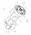
- Fig. 2 is a perspective view of an exemplary support assembly 200 that may be used to adjust inner turbine casing 100 with respect to an outer turbine casing (not shown in Fig. 2 ).
- support assembly 200 includes a wedge 202, a rod 204, a bushing 206, and a lock plate 208.
- a longitudinal axis 210 of support assembly 200 extends through a center 212 of rod 204.
- bushing 206 is substantially cylindrical and includes at least two recesses 214 defined therein. Recesses 214 enable a rotational position of bushing 206 to be secured with respect to an outer turbine casing (not shown in Fig. 2 ), as described in detail below. Alternatively, bushing 206 may not include recesses 214.
- bushing 206 includes a rod aperture 207 defined therethrough. Rod 204 extends through aperture 207 to slidably engage bushing 206.
- Lock plate 208 threadably engages a threaded end 216 of rod 204. To adjust support assembly 200, lock plate 208 is rotated about longitudinal axis 210, as described in more detail below. Lock plate 208 can be rotated using, for example, a spanner wrench and/or any other suitable powered and/or unpowered tool.
- Wedge 202 includes a wedge block 220 and a shim 222.
- rod 204 is press-fit and/or doweled into wedge block 220.
- rod 204 may be coupled to wedge block 220 using any coupling means that enables support assembly 200 to function as described herein.
- Shim 222 contacts support arm 108 and/or substantially horizontal surface 110 and supports inner turbine casing 100, as described in detail below.
- Shim 222 may include a thin piece of material and/or a coating that forms a wear interface on wedge block 220.
- Wedge 202 slidably engages a ledge 230 that includes a surface 232 that is inclined with respect to substantially horizontal surface 110 of inner turbine casing 100.
- ledge 230 includes a first retaining flange 234 and a second retaining flange 236 that each receive and position wedge 202 relative to inclined surface 232.
- ledge 230 may not include first and second retaining flanges 234 and 236.
- inclined surface 232 is substantially parallel to longitudinal axis 210.
- Support assembly 200 includes a plurality of fastening devices 240 that are used to secure support assembly 200 to an outer turbine casing (not shown in Fig. 2 ). Moreover, fastening devices 240 are used to secure lock plate 208 with respect to bushing 206. In the exemplary embodiment, each fastening device 240 includes a bolt 242 and a washer 244. Alternatively, fastening device 240 may include any other fastening mechanism that enables support assembly 200 to function as described herein.
- Fig. 3 is a perspective cut-away view of a portion of an exemplary turbine casing assembly 300.
- turbine casing assembly 300 includes inner turbine casing 100 and an outer turbine casing 302 radially outward of inner turbine casing 100 that extends to substantially circumscribe inner turbine casing 100.
- Outer turbine casing 302 includes at least one aperture 304 defined therethrough. Each aperture 304 is sized and oriented to receive support assembly 200 therein.
- fastening devices 240 are inserted through bushing 206 and into fastening apertures 306 defined within outer turbine casing 302. Further, when fastening devices 240 are secured in place, lock plate 208 is secured with respect to bushing 206 along longitudinal axis 210.
- lower half 303 of outer turbine casing 302 includes at least one coupling aperture 308 defined therethrough for coupling an upper half (not shown in Fig. 3 ) of outer turbine casing 302 to lower half 303.
- at least one recess 214 is substantially aligned with respect to coupling aperture 308. Accordingly, when a suitable fastening device, such as a bolt and/or pin, is inserted into coupling aperture 308 to couple the upper half to lower half 303, the rotational position of bushing 206 is secured with respect to outer turbine casing 302.
- a suitable fastening device such as a bolt and/or pin
- support assembly 200 can be inserted through aperture 304 when installing support assembly 200 in turbine casing assembly 300.
- bushing 206 may be formed integrally with outer turbine casing 302. Further, in some embodiments, depending on a spacing of coupling apertures 308, coupling apertures 308 do not align with bushing 206 and/or recess 214.
- wedge 202 contacts substantially horizontal surface 110 of inner turbine casing 100. More specifically, wedge 202 contacts a support arm 108 of inner turbine casing 100. As wedge 202 is slidably forced along inclined surface 232 in a direction D I , inner turbine casing 100 is moved in a substantially vertical direction D V . Accordingly, support assembly 200 can be adjusted to selectively change a position of inner turbine casing 100 relative to outer turbine casing 302.
- ledge 230 is a separate component coupled to outer turbine casing 302. Alternatively, ledge 230 may be formed integrally with outer turbine casing 302.
- lock plate 208 is rotated about longitudinal axis 210.
- Lock plate 208 can be rotated using, for example, a spanner wrench and/or any other suitable powered and/or unpowered tool. Because fastening devices 240 secure lock plate 208 in position with respect to bushing 206 along longitudinal axis 210, when lock plate 208 is rotated, lock plate 208 does not move in direction D I . Rather, because lock plate 208 is threadably coupled with rod 204, when lock plate 208 is rotated, rod 204 and wedge 202 are moved in direction D I . More specifically, as lock plate 208 is rotated, rod 204 slides in direction D I with respect to bushing 206.
- inner turbine casing 100 when lock plate 208 is rotated in a first direction, inner turbine casing 100 is elevated with respect to outer turbine casing 302, and when lock plate 208 is rotated in a second direction that is opposite to the first direction, inner turbine casing 100 is lowered with respect to outer turbine casing 302.
- support assembly 200 can be adjusted externally from turbine casing assembly 300 such that casing assembly 300 does not need to be disassembled to adjust inner turbine casing 100 with respect to outer turbine casing 302. Further, if support assembly 200 malfunctions or is damaged, outer turbine casing 302 does not need to be disassembled. Rather, in such an instance, fastening devices 240 can be removed from fastening apertures 306 to enable support assembly 200 to be removed from aperture 304. Further, in the event of extensive damage to support assembly 200 and/or turbine casing assembly 300, a cutting torch or similar tool may be used to cut through fastening devices 240 to enable at least a portion of support assembly 200 to be removed from within turbine casing assembly 300.
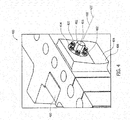
- Fig. 4 is a perspective view of an alternate turbine casing assembly 400.
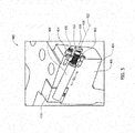
- Fig. 5 is a perspective cut-away view of turbine casing assembly 400.
- Turbine casing assembly 400 includes a support assembly 402 extending through a lower half 404 of an outer turbine casing 406. Similar to support assembly 200 (shown in Fig. 2 ), support assembly 402 includes a rod 408 and a wedge 410. Support assembly 402 also includes an adjustment nut 412 threadably coupled to rod 408 and a retainer plate 414 that secures adjustment nut 412 with respect to lower half 404. A head 416 of adjustment nut 412 extends through an aperture 418 defined through retainer plate 414.
- a plurality of fastening devices 420 secure support assembly 402 to outer turbine casing 406, similar to fastening devices 240 (shown in Fig. 2 ). Moreover, fastening devices 420 secure adjustment nut 412 with respect to outer turbine casing 406.
- adjustment nut 412 is rotated about a longitudinal axis 422 of support assembly 402, similar to rotating lock plate 208 about longitudinal axis 210 (both shown in Figs. 2 and 3 ).
- head 416 is shaped to mate with a suitable rotation tool. In the exemplary embodiment, head 416 forms a hexagonal nut that mates with a corresponding wrench. Alternatively, head 416 may be shaped to mate with any other suitable powered and/or unpowered tool.
- Support assembly 402 operates substantially similar to support assembly 200 (shown in Figs. 2 and 3 ). More specifically, because fastening devices 420 secure adjustment nut 412 in position with respect to outer turbine casing 406 along longitudinal axis 422, when adjustment nut 412 is rotated, rod 408 and wedge 410 slide in direction D I with respect to outer turbine casing 406. Accordingly, similar to support assembly 200 (shown in Figs. 2 and 3 ), support assembly 402 is externally adjustable.
- Turbine casing assembly 600 includes a first support assembly 602 extending through a lower half 604 of an outer turbine casing 606 and a second support assembly 608 extending through an upper half 610 of outer turbine casing 606.
- first support assembly 602 Similar to support assembly 200 (shown in Fig. 2 ), first support assembly 602 and includes a first rod 612 and a first wedge 614, and second support assembly 608 includes a second rod 616 and a second wedge 618.
- First support assembly 602 includes a first lock plate 620 threadably coupled to first rod 612 and second support assembly 608 includes a second lock plate 622 threadably coupled to second rod 616.
- a support arm 624 similar to support arm 108 (shown in Fig. 3 ) of an inner turbine casing 626 is positioned between first wedge 614 and second wedge 618.
- a plurality of fastening devices 630 secure first and second support assemblies 602 and 608 to outer turbine casing 606, similar to fastening devices 240 (shown in Fig. 2 ). Moreover, fastening devices 630 secure first and second lock plates 620 and 622 with respect to outer turbine casing 606. To adjust a position of first support assembly 602, first lock plate 620 is rotated about a longitudinal axis 632 of first support assembly 602, similar to rotating lock plate 208 about longitudinal axis 210 (both shown in Figs. 2 and 3 ). Similarly, to adjust a position of second support assembly 608, second lock plate 622 is rotated about a longitudinal axis 634 of second support assembly 608. First and second lock plates 620 and 622 can be rotated using, for example, a spanner wrench and/or any other suitable powered and/or unpowered tool.
- First and second support assemblies 602 and 608 operate substantially similar to support assembly 200 (shown in Figs. 2 and 3 ). More specifically, because fastening devices 630 secure first lock plate 620 in position with respect to lower half 604 along longitudinal axis 632, when first lock plate 620 is rotated, first rod 612 and first wedge 614 slide in a direction D I ; with respect to outer turbine casing 606. Similarly, because fastening devices 630 secure second lock plate 622 in position with respect to upper half 610 along longitudinal axis 634, when second lock plate 622 is rotated, second rod 616 and second wedge 618 slide in direction D Iii with respect to outer turbine casing 606. Accordingly, similar to support assembly 200 (shown in Figs.
- first and second support assemblies 602 and 608 are externally adjustable.
- first support assembly 602 and/or second support assembly 608 are adjustable to move inner turbine casing 626 in a substantially vertical direction D V .
- components inside turbine casing assembly 600 such as a rotor, may generate a torque that causes support arm 624 to lift up from first wedge 614.
- second support assembly 608 facilitates preventing inner turbine casing 626 from lifting up from first wedge 614.
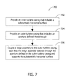
- Fig. 7 is a flow chart of an exemplary method 700 that may be used for assembling a turbine casing assembly such as turbine casing assembly 300.
- An inner turbine casing such as casing 100 is provided 702.
- the inner turbine casing includes a substantially horizontal surface such as surface 110.
- An outer turbine casing including an aperture defined therethrough is provided 704, such as outer turbine casing 302.
- the outer turbine casing is radially outward from the inner turbine casing.
- a support assembly such as support assembly 200 is coupled 706 to the outer turbine casing such that the support assembly extends through the aperture defined in the outer turbine casing.
- the support assembly supports the substantially horizontal surface of the inner turbine casing.
- the support assembly may include a wedge 202, rod 204, and lock plate 208 to facilitate adjusting the inner turbine casing with respect to the outer turbine casing.
- the methods and apparatus described herein facilitate adjustment of a turbine casing assembly.
- an externally adjustable support assembly is provided that facilitates adjustment of an inner turbine casing with respect to an outer turbine casing and alignment of the inner turbine casing with respect to internal components, such as a rotor.
- the support assembly described herein also facilitates adjusting a turbine casing assembly without requiring an outer turbine casing to be disassembled prior to adjustment.
- the methods and apparatus described herein facilitate reducing repair and replacement costs associated with turbine adjustment systems.
- the methods and apparatus described herein facilitate decreasing the time and effort necessary to adjust a turbine casing assembly, because the present invention enables the external adjustment of a turbine casing assembly.
- the support assembly described herein enables the inner turbine casing to be adjusted relative to the outer turbine casing to be aligned relative to internal components without disassembly.
- the support assembly described herein can be replaced and/or repaired more efficiently in the event of malfunction or damage to the support assembly and/or turbine casing assembly.
Landscapes
- Engineering & Computer Science (AREA)
- Mechanical Engineering (AREA)
- General Engineering & Computer Science (AREA)
- Turbine Rotor Nozzle Sealing (AREA)
- Mounting Of Bearings Or Others (AREA)
- Support Of The Bearing (AREA)
- Structures Of Non-Positive Displacement Pumps (AREA)
Abstract
Description
- The present invention relates generally to turbine engine assemblies, and more particularly, to support assemblies that facilitate adjusting turbine engine assemblies.
- At least some known industrial turbines, such as gas and/or steam turbines, include an inner casing mounted to an outer casing. Adjustment of the inner turbine casing relative to the outer turbine casing facilitates aligning the inner casing with respect to internal rotating components, reducing clearances and increasing an operating efficiency of the turbine and reducing engine to engine variation. However, given the weight and size of at least some known inner and outer turbine casing, adjusting and/or aligning the components with respect to one another during maintenance procedures, for example, may be time-consuming, difficult, and expensive.
- To facilitate assembly of turbine casings, at least some known adjustment systems are used. At least some of such known turbine adjustment systems are located entirely within the outer turbine casing. However, although convenient, such turbine adjustment systems are not externally adjustable. Accordingly, to adjust the inner and outer turbine casing relative to each other, the outer turbine casing must first be disassembled to gain access to the adjustment system. Further, in at least some known adjustment systems, the final adjustment must be performed with an upper half of the outer turbine casing removed. However, mounting the upper half of the outer turbine casing after final adjustment may itself offset and/or alter the adjustment. Similarly, if the turbine adjustment system malfunctions or is damaged, the outer turbine casing must first be disassembled before beginning any repair and/or replacement of the turbine adjustment system. Accordingly, the benefits of such adjustment systems may be limited.
- In one aspect, a turbine assembly is provided. The turbine assembly includes an inner turbine casing and an outer turbine casing radially outward from the inner turbine casing, the outer turbine casing comprising an aperture extending therethrough and a support assembly extending through the aperture, the support assembly externally adjustable outside of the outer turbine casing to adjust the inner turbine casing relative to the outer turbine casing.
- In another aspect, an adjustment system for adjusting a turbine assembly is provided. The adjustment system includes a wedge configured to support a substantially horizontal surface of an inner turbine casing, a ledge comprising a surface that is inclined with respect to the substantially horizontal surface, the ledge configured to be coupled to an outer turbine casing that is radially outward from the inner turbine casing, the wedge is slidably coupled to the ledge inclined surface. The adjustment system further includes a rod coupled to the wedge and a plate threadably coupled to the rod for selectively moving the wedge across the ledge inclined surface when the plate is rotated about the rod.
- In yet another aspect, a method of assembling a turbine casing assembly is provided. The method includes providing an inner turbine casing including a substantially horizontal surface, providing an outer turbine casing including an aperture defined therethrough, wherein the outer turbine casing is radially outward from the inner turbine casing, and coupling a support assembly to the outer turbine casing such that the support assembly extends through the aperture defmed in the outer turbine casing and supports the substantially horizontal surface of the inner turbine casing.
-
-
Fig. 1 is a perspective view of an exemplary inner turbine casing. -
Fig. 2 is a perspective view of an exemplary support assembly that may be used to support the inner turbine casing shown inFig. 1 . -
Fig. 3 is a perspective cut-away view of an exemplary turbine casing assembly that may be used with the support assembly shown inFig. 2 . -
Fig. 4 is a perspective view of an alternate turbine casing assembly. -
Fig. 5 is a perspective cut-away view of the turbine casing assembly shown inFig. 4 . -
Fig. 6 is a perspective cut-away view of an alternate turbine casing assembly. -
Fig. 7 is a flow chart of an exemplary method for that may be used for assembling the turbine casing assembly shown inFig. 3 . - The methods and apparatus described herein facilitate adjustment of a turbine casing assembly. Specifically, an externally adjustable support assembly is provided that facilitates adjustment of an inner turbine casing with respect to an outer turbine casing and alignment of the inner turbine casing with respect to internal components, such as a rotor. Moreover, the support assembly described herein also facilitates adjusting a turbine casing assembly without requiring an outer turbine casing to be disassembled prior to adjustment. Furthermore, the methods and apparatus described herein facilitate reducing repair and replacement costs associated with turbine adjustment systems.
-
Fig. 1 is a perspective view of an exemplaryinner turbine casing 100. In the exemplary embodiment,inner turbine casing 100 includes anupper half 102 and alower half 104. Alternatively,inner turbine casing 100 may be unitarily formed. To assembleinner turbine casing 100, bolts (not shown) or any other suitable fasteners are inserted throughapertures 106 defined in upper andlower halves lower halves Inner turbine casing 100 includes a plurality ofsupport arms 108 that facilitate adjustinginner turbine casing 100 with respect to an outer turbine casing (not shown inFig. 1 ). More specifically, in the exemplary embodiment,inner turbine casing 100 includes twosupport arms 108. Alternatively,inner turbine casing 100 may include any number ofsupport arms 108 that enablesinner turbine casing 100 to function as described herein. Eachsupport arm 108 defines a substantiallyhorizontal surface 110 oninner turbine casing 100. Internal components (not shown), such as rotor blades, stator vanes, nozzles, shrouds, and/or buckets, operate withininner turbine casing 100. Adjustinginner turbine casing 100, as described in detail below, facilitates reducing clearances betweeninner turbine casing 100 and internal components, increasing an operating efficiency of the turbine and reducing engine to engine variation. -
Fig. 2 is a perspective view of anexemplary support assembly 200 that may be used to adjustinner turbine casing 100 with respect to an outer turbine casing (not shown inFig. 2 ). In the exemplary embodiment,support assembly 200 includes awedge 202, arod 204, a bushing 206, and alock plate 208. Alongitudinal axis 210 ofsupport assembly 200 extends through acenter 212 ofrod 204. - In the exemplary embodiment, bushing 206 is substantially cylindrical and includes at least two
recesses 214 defined therein.Recesses 214 enable a rotational position ofbushing 206 to be secured with respect to an outer turbine casing (not shown inFig. 2 ), as described in detail below. Alternatively, bushing 206 may not includerecesses 214. In the exemplary embodiment, bushing 206 includes arod aperture 207 defined therethrough. Rod 204 extends throughaperture 207 to slidably engage bushing 206.Lock plate 208 threadably engages a threadedend 216 ofrod 204. To adjustsupport assembly 200,lock plate 208 is rotated aboutlongitudinal axis 210, as described in more detail below.Lock plate 208 can be rotated using, for example, a spanner wrench and/or any other suitable powered and/or unpowered tool. - Wedge 202 includes a
wedge block 220 and ashim 222. In the exemplary embodiment,rod 204 is press-fit and/or doweled intowedge block 220. Alternatively,rod 204 may be coupled towedge block 220 using any coupling means that enablessupport assembly 200 to function as described herein. Shim 222contacts support arm 108 and/or substantiallyhorizontal surface 110 and supportsinner turbine casing 100, as described in detail below. Shim 222 may include a thin piece of material and/or a coating that forms a wear interface onwedge block 220. - Wedge 202 slidably engages a ledge 230 that includes a
surface 232 that is inclined with respect to substantiallyhorizontal surface 110 ofinner turbine casing 100. In the exemplary embodiment,ledge 230 includes a first retaining flange 234 and a secondretaining flange 236 that each receive andposition wedge 202 relative toinclined surface 232. Alternatively, ledge 230 may not include first andsecond retaining flanges 234 and 236. Moreover, in the exemplary embodiment,inclined surface 232 is substantially parallel tolongitudinal axis 210. -
Support assembly 200 includes a plurality offastening devices 240 that are used to securesupport assembly 200 to an outer turbine casing (not shown inFig. 2 ). Moreover,fastening devices 240 are used to securelock plate 208 with respect tobushing 206. In the exemplary embodiment, eachfastening device 240 includes abolt 242 and awasher 244. Alternatively,fastening device 240 may include any other fastening mechanism that enablessupport assembly 200 to function as described herein. -
Fig. 3 is a perspective cut-away view of a portion of an exemplaryturbine casing assembly 300. In the exemplary embodiment,turbine casing assembly 300 includesinner turbine casing 100 and anouter turbine casing 302 radially outward ofinner turbine casing 100 that extends to substantially circumscribeinner turbine casing 100. For clarity, in the embodiment shown inFigure 3 , only a lower half 303 ofouter turbine casing 302 is shown.Outer turbine casing 302 includes at least oneaperture 304 defined therethrough. Eachaperture 304 is sized and oriented to receivesupport assembly 200 therein. To securesupport assembly 200 toouter turbine casing 302,fastening devices 240 are inserted throughbushing 206 and intofastening apertures 306 defined withinouter turbine casing 302. Further, when fasteningdevices 240 are secured in place,lock plate 208 is secured with respect tobushing 206 alonglongitudinal axis 210. - In the exemplary embodiment, lower half 303 of
outer turbine casing 302 includes at least onecoupling aperture 308 defined therethrough for coupling an upper half (not shown inFig. 3 ) ofouter turbine casing 302 to lower half 303. Further, in one embodiment, when bushing 206 is secured toouter turbine casing 302, at least onerecess 214 is substantially aligned with respect tocoupling aperture 308. Accordingly, when a suitable fastening device, such as a bolt and/or pin, is inserted intocoupling aperture 308 to couple the upper half to lower half 303, the rotational position ofbushing 206 is secured with respect toouter turbine casing 302. In the exemplary embodiment,bushing 206 is a separate component fromouter turbine casing 302. In such an embodiment, all ofsupport assembly 200 can be inserted throughaperture 304 when installingsupport assembly 200 inturbine casing assembly 300. Alternatively,bushing 206 may be formed integrally withouter turbine casing 302. Further, in some embodiments, depending on a spacing ofcoupling apertures 308,coupling apertures 308 do not align withbushing 206 and/orrecess 214. - During assembly, wedge 202 contacts substantially
horizontal surface 110 ofinner turbine casing 100. More specifically, wedge 202 contacts asupport arm 108 ofinner turbine casing 100. Aswedge 202 is slidably forced alonginclined surface 232 in a direction DI,inner turbine casing 100 is moved in a substantially vertical direction DV. Accordingly,support assembly 200 can be adjusted to selectively change a position ofinner turbine casing 100 relative toouter turbine casing 302. In the exemplary embodiment,ledge 230 is a separate component coupled toouter turbine casing 302. Alternatively,ledge 230 may be formed integrally withouter turbine casing 302. - To adjust a position of
support assembly 200,lock plate 208 is rotated aboutlongitudinal axis 210.Lock plate 208 can be rotated using, for example, a spanner wrench and/or any other suitable powered and/or unpowered tool. Becausefastening devices 240secure lock plate 208 in position with respect tobushing 206 alonglongitudinal axis 210, whenlock plate 208 is rotated,lock plate 208 does not move in direction DI. Rather, becauselock plate 208 is threadably coupled withrod 204, whenlock plate 208 is rotated,rod 204 andwedge 202 are moved in direction DI. More specifically, aslock plate 208 is rotated,rod 204 slides in direction DI with respect tobushing 206. As such, whenlock plate 208 is rotated in a first direction,inner turbine casing 100 is elevated with respect toouter turbine casing 302, and whenlock plate 208 is rotated in a second direction that is opposite to the first direction,inner turbine casing 100 is lowered with respect toouter turbine casing 302. - Notably,
support assembly 200 can be adjusted externally fromturbine casing assembly 300 such thatcasing assembly 300 does not need to be disassembled to adjustinner turbine casing 100 with respect toouter turbine casing 302. Further, ifsupport assembly 200 malfunctions or is damaged,outer turbine casing 302 does not need to be disassembled. Rather, in such an instance,fastening devices 240 can be removed fromfastening apertures 306 to enablesupport assembly 200 to be removed fromaperture 304. Further, in the event of extensive damage to supportassembly 200 and/orturbine casing assembly 300, a cutting torch or similar tool may be used to cut throughfastening devices 240 to enable at least a portion ofsupport assembly 200 to be removed from withinturbine casing assembly 300. -
Fig. 4 is a perspective view of an alternateturbine casing assembly 400.Fig. 5 is a perspective cut-away view ofturbine casing assembly 400.Turbine casing assembly 400 includes asupport assembly 402 extending through alower half 404 of anouter turbine casing 406. Similar to support assembly 200 (shown inFig. 2 ),support assembly 402 includes arod 408 and awedge 410.Support assembly 402 also includes anadjustment nut 412 threadably coupled torod 408 and aretainer plate 414 that securesadjustment nut 412 with respect tolower half 404. Ahead 416 ofadjustment nut 412 extends through anaperture 418 defined throughretainer plate 414. - A plurality of
fastening devices 420secure support assembly 402 toouter turbine casing 406, similar to fastening devices 240 (shown inFig. 2 ). Moreover,fastening devices 420secure adjustment nut 412 with respect toouter turbine casing 406. To adjust a position ofsupport assembly 402,adjustment nut 412 is rotated about alongitudinal axis 422 ofsupport assembly 402, similar torotating lock plate 208 about longitudinal axis 210 (both shown inFigs. 2 and3 ). To facilitate rotation ofadjustment nut 412,head 416 is shaped to mate with a suitable rotation tool. In the exemplary embodiment,head 416 forms a hexagonal nut that mates with a corresponding wrench. Alternatively,head 416 may be shaped to mate with any other suitable powered and/or unpowered tool. -
Support assembly 402 operates substantially similar to support assembly 200 (shown inFigs. 2 and3 ). More specifically, becausefastening devices 420secure adjustment nut 412 in position with respect toouter turbine casing 406 alonglongitudinal axis 422, whenadjustment nut 412 is rotated,rod 408 andwedge 410 slide in direction DI with respect toouter turbine casing 406. Accordingly, similar to support assembly 200 (shown inFigs. 2 and3 ),support assembly 402 is externally adjustable. -
Fig. 6 is a perspective cut-away view of an alternateturbine casing assembly 600.Turbine casing assembly 600 includes afirst support assembly 602 extending through alower half 604 of anouter turbine casing 606 and asecond support assembly 608 extending through anupper half 610 ofouter turbine casing 606. - Similar to support assembly 200 (shown in
Fig. 2 ),first support assembly 602 and includes afirst rod 612 and afirst wedge 614, andsecond support assembly 608 includes asecond rod 616 and asecond wedge 618.First support assembly 602 includes afirst lock plate 620 threadably coupled tofirst rod 612 andsecond support assembly 608 includes asecond lock plate 622 threadably coupled tosecond rod 616. Asupport arm 624 similar to support arm 108 (shown inFig. 3 ) of aninner turbine casing 626 is positioned betweenfirst wedge 614 andsecond wedge 618. - A plurality of
fastening devices 630 secure first andsecond support assemblies outer turbine casing 606, similar to fastening devices 240 (shown inFig. 2 ). Moreover,fastening devices 630 secure first andsecond lock plates outer turbine casing 606. To adjust a position offirst support assembly 602,first lock plate 620 is rotated about alongitudinal axis 632 offirst support assembly 602, similar torotating lock plate 208 about longitudinal axis 210 (both shown inFigs. 2 and3 ). Similarly, to adjust a position ofsecond support assembly 608,second lock plate 622 is rotated about alongitudinal axis 634 ofsecond support assembly 608. First andsecond lock plates - First and
second support assemblies Figs. 2 and3 ). More specifically, becausefastening devices 630 securefirst lock plate 620 in position with respect tolower half 604 alonglongitudinal axis 632, whenfirst lock plate 620 is rotated,first rod 612 andfirst wedge 614 slide in a direction DI; with respect toouter turbine casing 606. Similarly, becausefastening devices 630 securesecond lock plate 622 in position with respect toupper half 610 alonglongitudinal axis 634, whensecond lock plate 622 is rotated,second rod 616 andsecond wedge 618 slide in direction DIii with respect toouter turbine casing 606. Accordingly, similar to support assembly 200 (shown inFigs. 2 and3 ), first andsecond support assemblies first support assembly 602 and/orsecond support assembly 608 are adjustable to moveinner turbine casing 626 in a substantially vertical direction DV. Further, during operation, components insideturbine casing assembly 600, such as a rotor, may generate a torque that causessupport arm 624 to lift up fromfirst wedge 614. Accordingly,second support assembly 608 facilitates preventinginner turbine casing 626 from lifting up fromfirst wedge 614. -
Fig. 7 is a flow chart of anexemplary method 700 that may be used for assembling a turbine casing assembly such asturbine casing assembly 300. An inner turbine casing such ascasing 100 is provided 702. The inner turbine casing includes a substantially horizontal surface such assurface 110. An outer turbine casing including an aperture defined therethrough is provided 704, such asouter turbine casing 302. The outer turbine casing is radially outward from the inner turbine casing. A support assembly such assupport assembly 200 is coupled 706 to the outer turbine casing such that the support assembly extends through the aperture defined in the outer turbine casing. The support assembly supports the substantially horizontal surface of the inner turbine casing. The support assembly may include awedge 202,rod 204, andlock plate 208 to facilitate adjusting the inner turbine casing with respect to the outer turbine casing. - The methods and apparatus described herein facilitate adjustment of a turbine casing assembly. Specifically, an externally adjustable support assembly is provided that facilitates adjustment of an inner turbine casing with respect to an outer turbine casing and alignment of the inner turbine casing with respect to internal components, such as a rotor. Moreover, the support assembly described herein also facilitates adjusting a turbine casing assembly without requiring an outer turbine casing to be disassembled prior to adjustment. Furthermore, the methods and apparatus described herein facilitate reducing repair and replacement costs associated with turbine adjustment systems.
- Moreover, as compared to known adjustment systems, the methods and apparatus described herein facilitate decreasing the time and effort necessary to adjust a turbine casing assembly, because the present invention enables the external adjustment of a turbine casing assembly. Further, as compared to known adjustment systems, the support assembly described herein enables the inner turbine casing to be adjusted relative to the outer turbine casing to be aligned relative to internal components without disassembly. Moreover, because the support assembly is externally accessible unlike known adjustment systems, the support assembly described herein can be replaced and/or repaired more efficiently in the event of malfunction or damage to the support assembly and/or turbine casing assembly.
- Exemplary embodiments of adjustment systems for turbine assemblies are described above in detail. The methods, apparatus, and systems are not limited to the specific embodiments described herein or to the specific illustrated support and turbine assemblies. While the invention has been described in terms of various specific embodiments, those skilled in the art will recognize that the invention can be practiced with modification within the spirit and scope of the claims.
- This written description uses examples to disclose the invention, including the best mode, and also to enable any person skilled in the art to practice the invention, including making and using any devices or systems and performing any incorporated methods. The patentable scope of the invention is defmed by the claims, and may include other examples that occur to those skilled in the art. Such other examples are intended to be within the scope of the claims if they have structural elements that do not differ from the literal language of the claims, or if they include equivalent structural elements with insubstantial differences from the literal language of the claims.
- For completeness, various aspects of the invention are now set out in the following numbered clauses:
- 1. A turbine assembly comprising
an inner turbine casing; and
an outer turbine casing radially outward from said inner turbine casing, said outer turbine casing comprising an aperture extending therethrough and a support assembly extending through said aperture, said support assembly externally adjustable outside of said outer turbine casing to adjust said inner turbine casing relative to said outer turbine casing. - 2. A turbine assembly in accordance with clause 1, wherein said support assembly is selectively adjustable to elevate and lower said inner turbine casing relative to said outer turbine casing.
- 3. A turbine assembly in accordance with clause 1, wherein said support assembly comprises:
- a ledge comprising a surface that is inclined with respect to a substantially horizontal surface of said inner turbine casing;
- a wedge slidably coupled to said ledge inclined surface;
- a rod coupled to said wedge; and
- a plate threadably coupled to said rod, said wedge is movable across said ledge inclined surface as said plate is rotated about said rod.
- 4. A turbine assembly in accordance with clause 3, wherein said ledge is formed integrally with said outer turbine casing.
- 5. A turbine assembly in accordance with clause 3, wherein a longitudinal axis of said rod extends substantially parallel to said ledge inclined surface.
- 6. A turbine assembly in accordance with clause 3, further comprising a bushing for coupling said support assembly to said outer turbine casing, said bushing slidably coupled to said rod.
- 7. A turbine assembly in accordance with clause 3, wherein said plate comprises a head shaped and oriented to facilitate rotation of said plate using a tool.
- 8. An adjustment system for adjusting a turbine assembly, said adjustment system comprising:
- a wedge configured to support a substantially horizontal surface of an inner turbine casing;
- a ledge comprising a surface that is inclined with respect to the substantially horizontal surface, said ledge configured to be coupled to an outer turbine casing that is radially outward from the inner turbine casing, said wedge is slidably coupled to said ledge inclined surface;
- a rod coupled to said wedge; and
- a plate threadably coupled to said rod for selectively moving said wedge across said ledge inclined surface when said plate is rotated about said rod.
- 9. An adjustment system in accordance with clause 8, wherein a longitudinal axis of said rod extends substantially parallel to said ledge inclined surface.
- 10. An adjustment system in accordance with clause 8, further comprising a bushing for coupling said adjustment system to the outer turbine casing, said bushing slidably coupled to said rod.
- 11. An adjustment system in accordance with clause 10, further comprising a plurality of fastening devices configured to secure said bushing to the outer turbine casing.
- 12. An adjustment system in accordance with clause 10, wherein said rod is configured to slide with respect to said bushing as said plate is rotated about said rod.
- 13. An adjustment system in accordance with clause 8, wherein said wedge is configured to support at least one support arm on the inner turbine casing.
- 14. An adjustment system in accordance with clause 8, wherein said plate comprises a head shaped and oriented to facilitate rotation of said plate using a tool.
- 15. A method of assembling a turbine casing assembly, said method comprising:
- providing an inner turbine casing including a substantially horizontal surface;
- providing an outer turbine casing including an aperture defined therethrough, wherein the outer turbine casing is radially outward from the inner turbine casing; and
- coupling a support assembly to the outer turbine casing such that the support assembly extends through the aperture defined in the outer turbine casing and supports the substantially horizontal surface of the inner turbine casing.
- 16. A method in accordance with clause 15, further comprising:
- adjusting the support assembly such that the inner turbine casing is adjusted relative to the outer turbine casing.
- 17. A method in accordance with clause 15, wherein coupling a support assembly comprises coupling a support assembly including a ledge including a surface that is inclined with respect to the substantially horizontal surface, a wedge slidably coupled to the ledge inclined surface, a rod coupled to the wedge, and a plate threadably coupled to the rod.
- 18. A method in accordance with clause 17, further comprising rotating the plate about the rod to cause the wedge to slide along the ledge inclined surface such that inner turbine casing is elevated relative to the outer turbine casing.
- 19. A method in accordance with clause 17, further comprising rotating the plate about the rod to cause the wedge to slide along the ledge inclined surface such that inner turbine casing is lowered relative to the outer turbine casing.
- 20. A method in accordance with clause 15, wherein providing an inner turbine casing comprises providing an inner turbine casing that includes at least one mounting flange configured to be supported by the support assembly.
Claims (15)
- A turbine assembly (300) comprising
an inner turbine casing (100); and
an outer turbine casing (302) radially outward from said inner turbine casing, said outer turbine casing comprising an aperture (304) extending therethrough and a support assembly (200) extending through said aperture, said support assembly being externally adjustable outside of said outer turbine casing to adjust said inner turbine casing relative to said outer turbine casing. - A turbine assembly (300) in accordance with claim 1, wherein said support assembly (200) is selectively adjustable to elevate and lower said inner turbine casing (100) relative to said outer turbine casing (302).
- A turbine assembly (300) in accordance with claim 1 or claim 2, wherein said support assembly (200) comprises:a ledge (230) comprising a surface (232) that is inclined with respect to a substantially horizontal surface (110) of said inner turbine casing (100);a wedge (202) slidably coupled to said ledge inclined surface;a rod (204) coupled to said wedge; anda plate (208) threadably coupled to said rod, said wedge being movable across said ledge inclined surface as said plate is rotated about said rod.
- A turbine assembly (300) in accordance with claim 3, wherein said ledge (230) is formed integrally with said outer turbine casing (302).
- A turbine assembly (300) in accordance with claim 3 or claim 4, wherein a longitudinal axis (210) of said rod (204) extends substantially parallel to said ledge inclined surface (232).
- A turbine assembly (300) in accordance with any one of claims 3 to 5, further comprising a bushing (206) for coupling said support assembly (200) to said outer turbine casing (302), said bushing slidably coupled to said rod (204).
- A turbine assembly (300) in accordance with any one of claims 3 to 6, wherein said plate (208) comprises a head (416) shaped and oriented to facilitate rotation of said plate using a tool.
- An adjustment system (200) for adjusting a turbine assembly (300), said adjustment system comprising:a wedge (202) configured to support a substantially horizontal surface (110) of an inner turbine casing (100);a ledge (230) comprising a surface (232) that is inclined with respect to the substantially horizontal surface, said ledge configured to be coupled to an outer turbine casing (302) that is radially outward from the inner turbine casing, said wedge is slidably coupled to said ledge inclined surface;a rod (204) coupled to said wedge; anda plate (208) threadably coupled to said rod for selectively moving said wedge across said ledge inclined surface when said plate is rotated about said rod.
- An adjustment system (200) in accordance with claim 8, wherein a longitudinal axis (210) of said rod (204) extends substantially parallel to said ledge inclined surface (232).
- An adjustment system (200) in accordance with claim 8 or claim 9, further comprising a bushing (206) for coupling said adjustment system to the outer turbine casing (302), said bushing slidably coupled to said rod (204).
- An adjustment system in accordance with claim 10, further comprising a plurality of fastening devices configured to secure said bushing to the outer turbine casing.
- An adjustment system in accordance with claim 10 or claim 11, wherein said rod is configured to slide with respect to said bushing as said plate is rotated about said rod.
- An adjustment system in accordance with any one of claims 8 to 12, wherein said wedge is configured to support at least one support arm on the inner turbine casing.
- An adjustment system in accordance with any one of claims 8 to 13, wherein said plate comprises a head shaped and oriented to facilitate rotation of said plate using a tool.
- A method of assembling a turbine casing assembly, said method comprising:providing an inner turbine casing including a substantially horizontal surface;providing an outer turbine casing including an aperture defined therethrough, wherein the outer turbine casing is radially outward from the inner turbine casing; andcoupling a support assembly to the outer turbine casing such that the support assembly extends through the aperture defined in the outer turbine casing and supports the substantially horizontal surface of the inner turbine casing.
Applications Claiming Priority (1)
| Application Number | Priority Date | Filing Date | Title |
|---|---|---|---|
| US13/208,829 US8870529B2 (en) | 2011-08-12 | 2011-08-12 | Methods and apparatus to facilitate turbine casing assembly |
Publications (3)
| Publication Number | Publication Date |
|---|---|
| EP2557277A2 true EP2557277A2 (en) | 2013-02-13 |
| EP2557277A3 EP2557277A3 (en) | 2015-11-18 |
| EP2557277B1 EP2557277B1 (en) | 2017-05-17 |
Family
ID=46603751
Family Applications (1)
| Application Number | Title | Priority Date | Filing Date |
|---|---|---|---|
| EP12179078.6A Active EP2557277B1 (en) | 2011-08-12 | 2012-08-02 | Method and Apparatus to Facilitate Turbine Casing Assembly |
Country Status (3)
| Country | Link |
|---|---|
| US (1) | US8870529B2 (en) |
| EP (1) | EP2557277B1 (en) |
| CN (2) | CN105351016B (en) |
Cited By (3)
| Publication number | Priority date | Publication date | Assignee | Title |
|---|---|---|---|---|
| EP2949887A1 (en) * | 2014-05-30 | 2015-12-02 | General Electric Company | Apparatus and method for adjusting an inner casing of a turbomachine |
| EP2568125A3 (en) * | 2011-09-07 | 2017-09-20 | General Electric Company | Turbine casing assembly mounting pin |
| JP2021092206A (en) * | 2019-12-11 | 2021-06-17 | 株式会社東芝 | Steam turbine |
Families Citing this family (4)
| Publication number | Priority date | Publication date | Assignee | Title |
|---|---|---|---|---|
| EP2837775B1 (en) * | 2013-08-15 | 2016-03-30 | ALSTOM Technology Ltd | Fixation device for turbine and method for applying fixation |
| EP2921658B8 (en) * | 2014-03-20 | 2017-07-19 | Ansaldo Energia Switzerland AG | Pullable drawer for a turbine and turbine with such a drawer |
| DE102015209568B4 (en) | 2015-05-26 | 2017-07-06 | MTU Aero Engines AG | Flange connection with a clamping device for connecting flange webs |
| JP7222956B2 (en) * | 2020-08-25 | 2023-02-15 | 三菱重工業株式会社 | Steam turbine casing assembly and disassembly method |
Family Cites Families (13)
| Publication number | Priority date | Publication date | Assignee | Title |
|---|---|---|---|---|
| US1067356A (en) * | 1913-03-26 | 1913-07-15 | Ljungstroems Angturbin Ab | Steam-turbine. |
| US3628884A (en) * | 1970-06-26 | 1971-12-21 | Westinghouse Electric Corp | Method and apparatus for supporting an inner casing structure |
| CH589799A5 (en) * | 1975-07-04 | 1977-07-15 | Bbc Brown Boveri & Cie | |
| US5088279A (en) * | 1990-03-30 | 1992-02-18 | General Electric Company | Duct support assembly |
| US5934684A (en) * | 1997-05-27 | 1999-08-10 | Brandon; Ronald Earl | Retractable segmented packing ring for fluid turbines having gravity springs to neutralize packing segment weight forces |
| JP4363799B2 (en) * | 2001-06-08 | 2009-11-11 | 株式会社東芝 | Turbine assembly transport stand, turbine assembly method using the stand, and transport method |
| US6402468B1 (en) | 2001-06-18 | 2002-06-11 | General Electric Company | Method and apparatus for axially aligning inner and outer turbine shell components |
| JP4801373B2 (en) * | 2005-05-16 | 2011-10-26 | 三菱重工業株式会社 | Turbine cabin structure |
| US7419355B2 (en) | 2006-02-15 | 2008-09-02 | General Electric Company | Methods and apparatus for nozzle carrier with trapped shim adjustment |
| US7520721B2 (en) | 2006-09-19 | 2009-04-21 | General Electric Company | System and method for aligning and sealing a turbine shell assembly |
| US8182207B2 (en) * | 2008-03-17 | 2012-05-22 | General Electric Company | Inner turbine shell support configuration and methods |
| EP2473712B1 (en) * | 2009-09-02 | 2013-07-03 | Siemens Aktiengesellschaft | A mounting apparatus |
| US8529198B2 (en) * | 2010-11-08 | 2013-09-10 | General Electric Company | External adjustment and measurement system for steam turbine nozzle assembly |
-
2011
- 2011-08-12 US US13/208,829 patent/US8870529B2/en active Active
-
2012
- 2012-08-02 EP EP12179078.6A patent/EP2557277B1/en active Active
- 2012-08-09 CN CN201510873691.0A patent/CN105351016B/en active Active
- 2012-08-09 CN CN201210282326.9A patent/CN102953774B/en active Active
Non-Patent Citations (1)
| Title |
|---|
| None |
Cited By (5)
| Publication number | Priority date | Publication date | Assignee | Title |
|---|---|---|---|---|
| EP2568125A3 (en) * | 2011-09-07 | 2017-09-20 | General Electric Company | Turbine casing assembly mounting pin |
| EP2949887A1 (en) * | 2014-05-30 | 2015-12-02 | General Electric Company | Apparatus and method for adjusting an inner casing of a turbomachine |
| JP2021092206A (en) * | 2019-12-11 | 2021-06-17 | 株式会社東芝 | Steam turbine |
| EP3842620A1 (en) * | 2019-12-11 | 2021-06-30 | Kabushiki Kaisha Toshiba | Steam turbine |
| US11174758B2 (en) | 2019-12-11 | 2021-11-16 | Kabushiki Kaisha Toshiba | Steam turbine |
Also Published As
| Publication number | Publication date |
|---|---|
| US8870529B2 (en) | 2014-10-28 |
| CN102953774B (en) | 2016-01-20 |
| CN105351016A (en) | 2016-02-24 |
| EP2557277B1 (en) | 2017-05-17 |
| US20130039749A1 (en) | 2013-02-14 |
| CN102953774A (en) | 2013-03-06 |
| EP2557277A3 (en) | 2015-11-18 |
| CN105351016B (en) | 2017-05-24 |
Similar Documents
| Publication | Publication Date | Title |
|---|---|---|
| EP2557277B1 (en) | Method and Apparatus to Facilitate Turbine Casing Assembly | |
| JP5627904B2 (en) | Alignment device for gas turbine casing | |
| JP6067283B2 (en) | System and method for modifying a rotor | |
| US11105342B2 (en) | Tool and method for removal of variable stator vane bushing | |
| JP7034665B2 (en) | Installing or removing turbine blades at the base of the turbine blades | |
| EP2949887A1 (en) | Apparatus and method for adjusting an inner casing of a turbomachine | |
| EP2772617A1 (en) | Rotary flow machine with support means and method for disassembling the machine | |
| KR102191182B1 (en) | Cantilever slide for installing and removing a rotor block | |
| CN105298561A (en) | Packing-off piece installation device of turbine stator blades and use method of packing-off piece installation device | |
| CN102744441A (en) | System and method for modifying a rotor | |
| EP3542032B1 (en) | Inlet guide vane removal tools and methods | |
| CN110656981B (en) | A kind of positioning method of TRT stator vane adjustable mechanism | |
| US11732613B2 (en) | Apparatus for removal or installation of turbine blade | |
| EP2811123A1 (en) | Apparatus for pivoting an upper portion of a turbine shell | |
| EP2730753B1 (en) | A system for assembling and disassembling a turbine section of a gas turbine | |
| EP3088691A1 (en) | Gas turbine disassembly method | |
| EP3477066B1 (en) | Installation apparatus for a load-coupling of a turbine system and method of installing a load-coupling in a turbine system | |
| US10533751B2 (en) | Combustion can maintenance apparatus and method | |
| CN114458393A (en) | A turbine first-stage stator blade support device | |
| EP4281650A1 (en) | Apparatus for removal or installation of turbine blade | |
| CN111637019A (en) | An assembly method of pitch system for offshore wind turbines | |
| US20240100638A1 (en) | Installation/removal device for one or more rotor blocks of a turbocharger assembly, and method | |
| KR20160021976A (en) | Apparatus and method to move the gas turbine rotor |
Legal Events
| Date | Code | Title | Description |
|---|---|---|---|
| PUAI | Public reference made under article 153(3) epc to a published international application that has entered the european phase |
Free format text: ORIGINAL CODE: 0009012 |
|
| AK | Designated contracting states |
Kind code of ref document: A2 Designated state(s): AL AT BE BG CH CY CZ DE DK EE ES FI FR GB GR HR HU IE IS IT LI LT LU LV MC MK MT NL NO PL PT RO RS SE SI SK SM TR |
|
| AX | Request for extension of the european patent |
Extension state: BA ME |
|
| PUAL | Search report despatched |
Free format text: ORIGINAL CODE: 0009013 |
|
| AK | Designated contracting states |
Kind code of ref document: A3 Designated state(s): AL AT BE BG CH CY CZ DE DK EE ES FI FR GB GR HR HU IE IS IT LI LT LU LV MC MK MT NL NO PL PT RO RS SE SI SK SM TR |
|
| AX | Request for extension of the european patent |
Extension state: BA ME |
|
| RIC1 | Information provided on ipc code assigned before grant |
Ipc: F01D 25/24 20060101ALI20151015BHEP Ipc: F01D 25/28 20060101ALI20151015BHEP Ipc: F01D 25/26 20060101AFI20151015BHEP |
|
| 17P | Request for examination filed |
Effective date: 20160518 |
|
| RBV | Designated contracting states (corrected) |
Designated state(s): AL AT BE BG CH CY CZ DE DK EE ES FI FR GB GR HR HU IE IS IT LI LT LU LV MC MK MT NL NO PL PT RO RS SE SI SK SM TR |
|
| GRAP | Despatch of communication of intention to grant a patent |
Free format text: ORIGINAL CODE: EPIDOSNIGR1 |
|
| RIC1 | Information provided on ipc code assigned before grant |
Ipc: F01D 25/28 20060101ALI20170113BHEP Ipc: F01D 25/26 20060101AFI20170113BHEP Ipc: F01D 25/24 20060101ALI20170113BHEP |
|
| INTG | Intention to grant announced |
Effective date: 20170202 |
|
| GRAS | Grant fee paid |
Free format text: ORIGINAL CODE: EPIDOSNIGR3 |
|
| GRAA | (expected) grant |
Free format text: ORIGINAL CODE: 0009210 |
|
| AK | Designated contracting states |
Kind code of ref document: B1 Designated state(s): AL AT BE BG CH CY CZ DE DK EE ES FI FR GB GR HR HU IE IS IT LI LT LU LV MC MK MT NL NO PL PT RO RS SE SI SK SM TR |
|
| REG | Reference to a national code |
Ref country code: GB Ref legal event code: FG4D |
|
| REG | Reference to a national code |
Ref country code: CH Ref legal event code: EP |
|
| REG | Reference to a national code |
Ref country code: IE Ref legal event code: FG4D |
|
| REG | Reference to a national code |
Ref country code: AT Ref legal event code: REF Ref document number: 894667 Country of ref document: AT Kind code of ref document: T Effective date: 20170615 |
|
| REG | Reference to a national code |
Ref country code: DE Ref legal event code: R096 Ref document number: 602012032486 Country of ref document: DE |
|
| REG | Reference to a national code |
Ref country code: NL Ref legal event code: MP Effective date: 20170517 |
|
| REG | Reference to a national code |
Ref country code: LT Ref legal event code: MG4D |
|
| REG | Reference to a national code |
Ref country code: AT Ref legal event code: MK05 Ref document number: 894667 Country of ref document: AT Kind code of ref document: T Effective date: 20170517 |
|
| PG25 | Lapsed in a contracting state [announced via postgrant information from national office to epo] |
Ref country code: GR Free format text: LAPSE BECAUSE OF FAILURE TO SUBMIT A TRANSLATION OF THE DESCRIPTION OR TO PAY THE FEE WITHIN THE PRESCRIBED TIME-LIMIT Effective date: 20170818 Ref country code: LT Free format text: LAPSE BECAUSE OF FAILURE TO SUBMIT A TRANSLATION OF THE DESCRIPTION OR TO PAY THE FEE WITHIN THE PRESCRIBED TIME-LIMIT Effective date: 20170517 Ref country code: HR Free format text: LAPSE BECAUSE OF FAILURE TO SUBMIT A TRANSLATION OF THE DESCRIPTION OR TO PAY THE FEE WITHIN THE PRESCRIBED TIME-LIMIT Effective date: 20170517 Ref country code: FI Free format text: LAPSE BECAUSE OF FAILURE TO SUBMIT A TRANSLATION OF THE DESCRIPTION OR TO PAY THE FEE WITHIN THE PRESCRIBED TIME-LIMIT Effective date: 20170517 Ref country code: NO Free format text: LAPSE BECAUSE OF FAILURE TO SUBMIT A TRANSLATION OF THE DESCRIPTION OR TO PAY THE FEE WITHIN THE PRESCRIBED TIME-LIMIT Effective date: 20170817 Ref country code: AT Free format text: LAPSE BECAUSE OF FAILURE TO SUBMIT A TRANSLATION OF THE DESCRIPTION OR TO PAY THE FEE WITHIN THE PRESCRIBED TIME-LIMIT Effective date: 20170517 Ref country code: ES Free format text: LAPSE BECAUSE OF FAILURE TO SUBMIT A TRANSLATION OF THE DESCRIPTION OR TO PAY THE FEE WITHIN THE PRESCRIBED TIME-LIMIT Effective date: 20170517 |
|
| PG25 | Lapsed in a contracting state [announced via postgrant information from national office to epo] |
Ref country code: RS Free format text: LAPSE BECAUSE OF FAILURE TO SUBMIT A TRANSLATION OF THE DESCRIPTION OR TO PAY THE FEE WITHIN THE PRESCRIBED TIME-LIMIT Effective date: 20170517 Ref country code: NL Free format text: LAPSE BECAUSE OF FAILURE TO SUBMIT A TRANSLATION OF THE DESCRIPTION OR TO PAY THE FEE WITHIN THE PRESCRIBED TIME-LIMIT Effective date: 20170517 Ref country code: IS Free format text: LAPSE BECAUSE OF FAILURE TO SUBMIT A TRANSLATION OF THE DESCRIPTION OR TO PAY THE FEE WITHIN THE PRESCRIBED TIME-LIMIT Effective date: 20170917 Ref country code: SE Free format text: LAPSE BECAUSE OF FAILURE TO SUBMIT A TRANSLATION OF THE DESCRIPTION OR TO PAY THE FEE WITHIN THE PRESCRIBED TIME-LIMIT Effective date: 20170517 Ref country code: BG Free format text: LAPSE BECAUSE OF FAILURE TO SUBMIT A TRANSLATION OF THE DESCRIPTION OR TO PAY THE FEE WITHIN THE PRESCRIBED TIME-LIMIT Effective date: 20170817 Ref country code: PL Free format text: LAPSE BECAUSE OF FAILURE TO SUBMIT A TRANSLATION OF THE DESCRIPTION OR TO PAY THE FEE WITHIN THE PRESCRIBED TIME-LIMIT Effective date: 20170517 Ref country code: LV Free format text: LAPSE BECAUSE OF FAILURE TO SUBMIT A TRANSLATION OF THE DESCRIPTION OR TO PAY THE FEE WITHIN THE PRESCRIBED TIME-LIMIT Effective date: 20170517 |
|
| PG25 | Lapsed in a contracting state [announced via postgrant information from national office to epo] |
Ref country code: RO Free format text: LAPSE BECAUSE OF FAILURE TO SUBMIT A TRANSLATION OF THE DESCRIPTION OR TO PAY THE FEE WITHIN THE PRESCRIBED TIME-LIMIT Effective date: 20170517 Ref country code: EE Free format text: LAPSE BECAUSE OF FAILURE TO SUBMIT A TRANSLATION OF THE DESCRIPTION OR TO PAY THE FEE WITHIN THE PRESCRIBED TIME-LIMIT Effective date: 20170517 Ref country code: DK Free format text: LAPSE BECAUSE OF FAILURE TO SUBMIT A TRANSLATION OF THE DESCRIPTION OR TO PAY THE FEE WITHIN THE PRESCRIBED TIME-LIMIT Effective date: 20170517 Ref country code: CZ Free format text: LAPSE BECAUSE OF FAILURE TO SUBMIT A TRANSLATION OF THE DESCRIPTION OR TO PAY THE FEE WITHIN THE PRESCRIBED TIME-LIMIT Effective date: 20170517 Ref country code: SK Free format text: LAPSE BECAUSE OF FAILURE TO SUBMIT A TRANSLATION OF THE DESCRIPTION OR TO PAY THE FEE WITHIN THE PRESCRIBED TIME-LIMIT Effective date: 20170517 |
|
| REG | Reference to a national code |
Ref country code: DE Ref legal event code: R097 Ref document number: 602012032486 Country of ref document: DE |
|
| PG25 | Lapsed in a contracting state [announced via postgrant information from national office to epo] |
Ref country code: SM Free format text: LAPSE BECAUSE OF FAILURE TO SUBMIT A TRANSLATION OF THE DESCRIPTION OR TO PAY THE FEE WITHIN THE PRESCRIBED TIME-LIMIT Effective date: 20170517 |
|
| PLBE | No opposition filed within time limit |
Free format text: ORIGINAL CODE: 0009261 |
|
| STAA | Information on the status of an ep patent application or granted ep patent |
Free format text: STATUS: NO OPPOSITION FILED WITHIN TIME LIMIT |
|
| REG | Reference to a national code |
Ref country code: CH Ref legal event code: PL |
|
| PG25 | Lapsed in a contracting state [announced via postgrant information from national office to epo] |
Ref country code: MC Free format text: LAPSE BECAUSE OF FAILURE TO SUBMIT A TRANSLATION OF THE DESCRIPTION OR TO PAY THE FEE WITHIN THE PRESCRIBED TIME-LIMIT Effective date: 20170517 |
|
| 26N | No opposition filed |
Effective date: 20180220 |
|
| GBPC | Gb: european patent ceased through non-payment of renewal fee |
Effective date: 20170817 |
|
| PG25 | Lapsed in a contracting state [announced via postgrant information from national office to epo] |
Ref country code: CH Free format text: LAPSE BECAUSE OF NON-PAYMENT OF DUE FEES Effective date: 20170831 Ref country code: LI Free format text: LAPSE BECAUSE OF NON-PAYMENT OF DUE FEES Effective date: 20170831 |
|
| REG | Reference to a national code |
Ref country code: FR Ref legal event code: ST Effective date: 20180430 |
|
| REG | Reference to a national code |
Ref country code: IE Ref legal event code: MM4A |
|
| PG25 | Lapsed in a contracting state [announced via postgrant information from national office to epo] |
Ref country code: SI Free format text: LAPSE BECAUSE OF FAILURE TO SUBMIT A TRANSLATION OF THE DESCRIPTION OR TO PAY THE FEE WITHIN THE PRESCRIBED TIME-LIMIT Effective date: 20170517 |
|
| REG | Reference to a national code |
Ref country code: BE Ref legal event code: MM Effective date: 20170831 |
|
| PG25 | Lapsed in a contracting state [announced via postgrant information from national office to epo] |
Ref country code: LU Free format text: LAPSE BECAUSE OF NON-PAYMENT OF DUE FEES Effective date: 20170802 |
|
| PG25 | Lapsed in a contracting state [announced via postgrant information from national office to epo] |
Ref country code: GB Free format text: LAPSE BECAUSE OF NON-PAYMENT OF DUE FEES Effective date: 20170817 Ref country code: IE Free format text: LAPSE BECAUSE OF NON-PAYMENT OF DUE FEES Effective date: 20170802 |
|
| PG25 | Lapsed in a contracting state [announced via postgrant information from national office to epo] |
Ref country code: BE Free format text: LAPSE BECAUSE OF NON-PAYMENT OF DUE FEES Effective date: 20170831 Ref country code: FR Free format text: LAPSE BECAUSE OF NON-PAYMENT OF DUE FEES Effective date: 20170831 |
|
| PG25 | Lapsed in a contracting state [announced via postgrant information from national office to epo] |
Ref country code: MT Free format text: LAPSE BECAUSE OF NON-PAYMENT OF DUE FEES Effective date: 20170802 |
|
| PG25 | Lapsed in a contracting state [announced via postgrant information from national office to epo] |
Ref country code: HU Free format text: LAPSE BECAUSE OF FAILURE TO SUBMIT A TRANSLATION OF THE DESCRIPTION OR TO PAY THE FEE WITHIN THE PRESCRIBED TIME-LIMIT; INVALID AB INITIO Effective date: 20120802 |
|
| PG25 | Lapsed in a contracting state [announced via postgrant information from national office to epo] |
Ref country code: CY Free format text: LAPSE BECAUSE OF NON-PAYMENT OF DUE FEES Effective date: 20170517 |
|
| PG25 | Lapsed in a contracting state [announced via postgrant information from national office to epo] |
Ref country code: MK Free format text: LAPSE BECAUSE OF FAILURE TO SUBMIT A TRANSLATION OF THE DESCRIPTION OR TO PAY THE FEE WITHIN THE PRESCRIBED TIME-LIMIT Effective date: 20170517 |
|
| PG25 | Lapsed in a contracting state [announced via postgrant information from national office to epo] |
Ref country code: TR Free format text: LAPSE BECAUSE OF FAILURE TO SUBMIT A TRANSLATION OF THE DESCRIPTION OR TO PAY THE FEE WITHIN THE PRESCRIBED TIME-LIMIT Effective date: 20170517 |
|
| PG25 | Lapsed in a contracting state [announced via postgrant information from national office to epo] |
Ref country code: PT Free format text: LAPSE BECAUSE OF FAILURE TO SUBMIT A TRANSLATION OF THE DESCRIPTION OR TO PAY THE FEE WITHIN THE PRESCRIBED TIME-LIMIT Effective date: 20170517 |
|
| PG25 | Lapsed in a contracting state [announced via postgrant information from national office to epo] |
Ref country code: AL Free format text: LAPSE BECAUSE OF FAILURE TO SUBMIT A TRANSLATION OF THE DESCRIPTION OR TO PAY THE FEE WITHIN THE PRESCRIBED TIME-LIMIT Effective date: 20170517 |
|
| REG | Reference to a national code |
Ref country code: DE Ref legal event code: R081 Ref document number: 602012032486 Country of ref document: DE Owner name: GENERAL ELECTRIC TECHNOLOGY GMBH, CH Free format text: FORMER OWNER: GENERAL ELECTRIC COMPANY, SCHENECTADY, NY, US |
|
| PGFP | Annual fee paid to national office [announced via postgrant information from national office to epo] |
Ref country code: DE Payment date: 20250724 Year of fee payment: 14 |
|
| PGFP | Annual fee paid to national office [announced via postgrant information from national office to epo] |
Ref country code: IT Payment date: 20250723 Year of fee payment: 14 |