EP2557276A2 - Variable stator vane control system - Google Patents
Variable stator vane control system Download PDFInfo
- Publication number
- EP2557276A2 EP2557276A2 EP12179182A EP12179182A EP2557276A2 EP 2557276 A2 EP2557276 A2 EP 2557276A2 EP 12179182 A EP12179182 A EP 12179182A EP 12179182 A EP12179182 A EP 12179182A EP 2557276 A2 EP2557276 A2 EP 2557276A2
- Authority
- EP
- European Patent Office
- Prior art keywords
- variable stator
- stator vane
- actuator
- control system
- communication
- Prior art date
- Legal status (The legal status is an assumption and is not a legal conclusion. Google has not performed a legal analysis and makes no representation as to the accuracy of the status listed.)
- Granted
Links
Images


Classifications
-
- F—MECHANICAL ENGINEERING; LIGHTING; HEATING; WEAPONS; BLASTING
- F01—MACHINES OR ENGINES IN GENERAL; ENGINE PLANTS IN GENERAL; STEAM ENGINES
- F01D—NON-POSITIVE DISPLACEMENT MACHINES OR ENGINES, e.g. STEAM TURBINES
- F01D17/00—Regulating or controlling by varying flow
- F01D17/10—Final actuators
- F01D17/12—Final actuators arranged in stator parts
- F01D17/14—Final actuators arranged in stator parts varying effective cross-sectional area of nozzles or guide conduits
- F01D17/16—Final actuators arranged in stator parts varying effective cross-sectional area of nozzles or guide conduits by means of nozzle vanes
- F01D17/162—Final actuators arranged in stator parts varying effective cross-sectional area of nozzles or guide conduits by means of nozzle vanes for axial flow, i.e. the vanes turning around axes which are essentially perpendicular to the rotor centre line
Definitions
- the present application and the resultant patent relate generally to gas turbine engines and more particularly relate to a variable stator vane control system so as to avoid mechanical interference with a rotor blade through the use of hydraulic actuators and electric trimmer motors.
- gas turbine engines include a compressor to compress an incoming flow of air for combustion with a compressed flow of fuel in a combustor.
- the compressor includes a number of progressively higher pressure stages. Each stage includes a row of rotor blades mounted on a rotor and a number of stator vanes mounted on a casing.
- the compressor also may use a number of variable stator vanes.
- the variable stator vanes generally extend between adjacent rotor blades.
- the variable stator vanes are rotatable about an axis so as to direct the airflow through the compressor.
- the variable stator vanes thus may control the quantity of air flowing through the compressor so as to facilitate optimized performance.
- the size and configuration of the variable stator vanes may vary.
- Control of the angle of the variable stator vanes thus is required so as to provide this optimized performance.
- Mechanical interference or clashing of rotor blades and the variable stator vanes may result if the variable stator vanes extend too far open or closed.
- Such mechanical inference or clashing may result in component damage.
- significant downtime thus may result from such clashing and may require extensive repair.
- variable stator vane control systems should avoid mechanical interference between the variable stator vanes and rotor blades while providing optimized airflow for overall system efficiency and output.
- variable stator vane control system may include a variable stator vane positioned by an actuator and a trimmer motor, a resolver to determine a position of the variable stator vane, and a controller in communication with the resolver, the actuator, and the trimmer motor to prevent over travel of the variable stator vane.
- the present application and the resultant patent further provide a method of controlling a variable stator vane by an actuator and a trimmer motor to prevent interference with a rotor blade.
- the method may include the step of determining a rotational position of the variable stator vane. If the variable stator vane is too far open, then closing the actuator and stopping the trimmer motor. If the variable stator vane is too far closed, then opening the actuator and stopping the trimmer motor.
- variable stator vane control system to prevent interference with a rotor blade.
- the variable stator vane control system may provide a number of variable stator vanes positioned on an actuation ring, the variable stator vanes positioned by an actuator and a trimmer motor in communication with the actuation ring, a resolver to determine a position of one or more of the variable stator vanes, and a controller in communication with the resolver, the actuator, and the trimmer motor to prevent interference with the rotor blade by the variable stator vanes.
- Fig. 1 shows a schematic view of gas turbine engine 10 as may be used herein.
- the gas turbine engine 10 may include a compressor 15.
- the compressor 15 compresses an incoming flow of air 20.
- the compressor 15 delivers the compressed flow of air 20 to a combustor 25.
- the combustor 25 mixes the compressed flow of air 20 with a compressed flow of fuel 30 and ignites the mixture to create a flow of combustion gases 35.
- the gas turbine engine 10 may include any number of combustors 25.
- the flow of combustion gases 35 is in turn delivered to a turbine 40.
- the flow of combustion gases 35 drives the turbine 40 so as to produce mechanical work.
- the mechanical work produced in the turbine 40 drives the compressor 15 via a shaft 45 and an external load 50 such as an electrical generator and the like.
- the gas turbine engine 10 may use natural gas, various types of syngas, and/or other types of fuels.
- the gas turbine engine 10 may be anyone of a number of different gas turbine engines offered by General Electric Company of Schenectady, New York, including, but not limited to, those such as a 7 or a 9 series heavy duty gas turbine engine and the like.
- the gas turbine engine 10 may have different configurations and may use other types of components.
- Other types of gas turbine engines also may be used herein.
- Multiple gas turbine engines, other types of turbines, and other types of power generation equipment also may be used herein together.
- the compressor 15 may include a number of variable stator vanes 55.
- the variable stator vanes 55 may have any desired size, shape, and configuration.
- the variable stator vanes 55 may be maneuvered via an actuator 60 in response to a controller 65.
- the controller 65 instructs the actuator 60 to rotate the variable stator vanes 55 according to any number of operational parameters to the appropriate angle.
- Fig. 2 shows a stage 70 of the compressor 15.
- Each stage includes a row of the variable stator vanes 55 and a row of rotor blades 75.
- Each variable stator vane 55 may include a stem 80.
- the stem 80 may protrude through a casing 85 of the compressor 15.
- the stem 80 may be attached to a lever arm 90 for rotation therewith.
- the lever arm 90 in turn may be in communication with an actuation ring 95.
- the actuation ring 95 may be in communication with the actuator 60 for movement therewith.
- the actuation ring 95 surrounds the casing 85.
- the actuator ring 95 may be in communication with a number of the lever arms 90 and the variable stator vanes 55. Movement of the actuation ring 95 thus translates into movement of the variable stator vanes 55.
- the actuator 60 may maneuver all of the variable stator vanes 55 on a given actuation ring 95 in unison through a range of vane angles.
- Other components and other configurations may
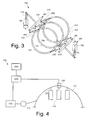
- Figs. 3 and 4 show a variable stator vane control system 100 as may be described herein.
- the variable stator vane control system 100 may be positioned within the compressor 15 in a manner similar to that described above.
- the variable stator vane control system 100 includes a number of variable stator vanes 110.
- the variable stator vanes 110 may have any desired size, shape, or configuration.
- Each variable stator vane 110 may have a stem 120 on one end thereof.
- Each variable stator vane 110 may be in communication with an actuation ring 130 via the stem 120.
- the actuation ring 130 may have any desired diameter and may surround the casing 85 of the compressor 15.
- One or more lever arms also may be used.
- Each actuation ring 130 may be in communication with an actuator 140.
- the actuator 140 may be a hydraulic actuator. Other types of actuating devices may be used herein. As is shown, a first actuator 150 and a second actuator 160 may be used, although any number of actuators 140 may be used herein.
- Each actuator 140 may have a piston 170 for linear drive and control. Other components and other configurations may be used herein.
- Each actuation ring 130 or a set thereof may be in communication with the actuators 140 via a linkage assembly 180.
- the linkage assembly 180 may have a crossbar 190 in communication with the piston 170 of each actuator 140.
- the crossbar 190 may include any number of ring arms 200 extending therefrom.
- Each ring arm 200 is in communication with an actuation ring 130. Any number of ring arms 200 and actuation rings 130 may be maneuvered by the crossbar 190.
- Each actuator 140 may have a linkage assembly 180 in communication therewith. Other components and other configurations may be used herein.
- Each ring arm 200 may be further maneuvered via a trimmer motor 210.
- the trimmer motor 210 may be an electrical motor and the like.
- the trimmer motor 210 allows for maneuvering of each ring arm 200 and, hence, each individual actuation ring 130 for more precise control as compared to the crossbar 190 and the actuator 140 maneuvering a number of actuation rings 130.
- Other components and other configurations may be used herein.
- the variable stator vane control system 100 also may include a controller 220.
- the controller 220 may be any type of programmable control device.
- the controller 220 may be used to control the various components of the gas turbine engine 10 in general or the compressor 15 in specific.
- the controller 220 also may be dedicated to the variable stator vane control system 100.
- the controller 220 may be in communication with each actuator 140 and each trimmer motor 210.
- the controller 220 also may be in communication with one or more resolvers 230.
- the resolvers 230 may determine the rotational position of one or more of the variable stator vanes 110. Other types of positioning sensors also may be used herein.
- the controller 220 also may be in communication with any number of other types of inputs 240.
- the inputs 240 may relate to any number of different operational parameters with respect to the variable stator vane control system 100 and/or the gas turbine engine 10 as a whole.
- Other types of controllers and other types of sensors also may be used herein.
- Other components and other configurations may be used herein.
- the actuators 140 may maneuver the variable stator vanes 110 on a number of actuation rings 130 in response to the controller 220.
- the trimmer motors 210 may provide more precise control on positioning of the variable stator vanes 110 on an individual actuation ring 130 or a portion thereof.
- the variable stator vanes 110 may rotate from a closed position 250 to an open position 260 based upon the stroke of the actuators 140.
- the linear position of the piston 170 of the actuators 140 drives the linkage assembly 180 and the actuation rings 130.
- more precise (but more limited) control may be provided by the trimmer motors 210 within a trim range 270.
- Full extension of the trimmer motor 210 may be restricted in the closed position 250 or the open position 260 due to mechanical restrictions with the adjacent rotor blades 75 or other components within the compressor 15.
- Fig. 6 shows an example of control logic to avoid such mechanical interference between the variable stator vanes 110 and the adjacent rotor blades 75.
- the resolvers 230 provide the rotational position for the vane angle for some or all of the variable stator vanes 110 to the controller 220.
- the controller 220 may take action via the actuators 140, the trimmer motors 210, and/or so as both to prevent mechanical interference in either the closed position 250, the open position 260, or elsewhere. If the controller 220 determines that the variable stator vanes 110 of a given actuation ring 130 are too far open, the controller 220 will close the actuators 140, stop the trimmer motors 210, and alert an operator.
- the controller 220 determines that the variable stator vanes 110 on a given actuation ring 130 are too far closed, the controller 220 will open the actuators 140, stop the trimmer motors 210, and alert an operator. The methods steps may be continuously repeated herein.
- the rotational information provided by the resolvers 230 thus may be utilized to bias or adjust the actuators 140 or the trimmer motors 210 to bring the variable stator vanes 110 to a safe position. For example, if the trimmers are retracted about five (5) degrees too far or so, the actuators 140 will bias themselves about five (5) degrees further open for a given actuation ring 130 such that mechanical limits are not realized and clashing with the rotor blades 75 may be prevented.
- variable stator vane control system 100 thus prevents mechanical interference or clashing of the variable stator vanes 110 and the rotor blades 75 due to over travel in both the closed position 250 and the open position 260 while allowing full validation of the system 100 as a whole. Such avoidance should reduce overall compressor maintenance and downtime while providing efficient operation.
Landscapes
- Engineering & Computer Science (AREA)
- Mechanical Engineering (AREA)
- General Engineering & Computer Science (AREA)
- Structures Of Non-Positive Displacement Pumps (AREA)
- Supercharger (AREA)
Abstract
Description
- The present application and the resultant patent relate generally to gas turbine engines and more particularly relate to a variable stator vane control system so as to avoid mechanical interference with a rotor blade through the use of hydraulic actuators and electric trimmer motors.
- Generally described, gas turbine engines include a compressor to compress an incoming flow of air for combustion with a compressed flow of fuel in a combustor. The compressor includes a number of progressively higher pressure stages. Each stage includes a row of rotor blades mounted on a rotor and a number of stator vanes mounted on a casing. The compressor also may use a number of variable stator vanes. The variable stator vanes generally extend between adjacent rotor blades. The variable stator vanes are rotatable about an axis so as to direct the airflow through the compressor. The variable stator vanes thus may control the quantity of air flowing through the compressor so as to facilitate optimized performance. The size and configuration of the variable stator vanes may vary.
- Control of the angle of the variable stator vanes thus is required so as to provide this optimized performance. Mechanical interference or clashing of rotor blades and the variable stator vanes, however, may result if the variable stator vanes extend too far open or closed. Such mechanical inference or clashing may result in component damage. Moreover, significant downtime thus may result from such clashing and may require extensive repair.
- There is thus a desire therefore for improved variable stator vane control systems. Such improved control systems should avoid mechanical interference between the variable stator vanes and rotor blades while providing optimized airflow for overall system efficiency and output.
- The present application and the resultant patent thus provide a variable stator vane control system. The variable stator vane control system may include a variable stator vane positioned by an actuator and a trimmer motor, a resolver to determine a position of the variable stator vane, and a controller in communication with the resolver, the actuator, and the trimmer motor to prevent over travel of the variable stator vane.
- The present application and the resultant patent further provide a method of controlling a variable stator vane by an actuator and a trimmer motor to prevent interference with a rotor blade. The method may include the step of determining a rotational position of the variable stator vane. If the variable stator vane is too far open, then closing the actuator and stopping the trimmer motor. If the variable stator vane is too far closed, then opening the actuator and stopping the trimmer motor.
- The present application and the resultant patent further provide a variable stator vane control system to prevent interference with a rotor blade. The variable stator vane control system may provide a number of variable stator vanes positioned on an actuation ring, the variable stator vanes positioned by an actuator and a trimmer motor in communication with the actuation ring, a resolver to determine a position of one or more of the variable stator vanes, and a controller in communication with the resolver, the actuator, and the trimmer motor to prevent interference with the rotor blade by the variable stator vanes.
- These and other features and improvements of the present application and the resultant patent will become apparent to one of ordinary skill in the art upon review of the following detailed description when taken in conjunction with the several drawings and the appended claims.
-
-
Fig. 1 is a schematic diagram of a gas turbine engine. -
Fig. 2 is a partial side cross-sectional view of a variable stator vane assembly. -
Fig. 3 is a partial perspective view of a variable stator vane control system as may be described herein. -
Fig. 4 is a schematic diagram of the variable stator vane control system ofFig. 3 . -
Fig. 5 is a graph showing vane angle versus actuator stroke. -
Fig. 6 is flowchart showing the control logic used in the variable stator vane control system ofFig. 3 . - Referring now to the drawings, in which like numerals refer to like elements throughout the several views,
Fig. 1 shows a schematic view ofgas turbine engine 10 as may be used herein. Thegas turbine engine 10 may include a compressor 15. The compressor 15 compresses an incoming flow ofair 20. The compressor 15 delivers the compressed flow ofair 20 to a combustor 25. The combustor 25 mixes the compressed flow ofair 20 with a compressed flow offuel 30 and ignites the mixture to create a flow of combustion gases 35. Although only a single combustor 25 is shown, thegas turbine engine 10 may include any number of combustors 25. The flow of combustion gases 35 is in turn delivered to a turbine 40. The flow of combustion gases 35 drives the turbine 40 so as to produce mechanical work. The mechanical work produced in the turbine 40 drives the compressor 15 via a shaft 45 and an external load 50 such as an electrical generator and the like. - The
gas turbine engine 10 may use natural gas, various types of syngas, and/or other types of fuels. Thegas turbine engine 10 may be anyone of a number of different gas turbine engines offered by General Electric Company of Schenectady, New York, including, but not limited to, those such as a 7 or a 9 series heavy duty gas turbine engine and the like. Thegas turbine engine 10 may have different configurations and may use other types of components. Other types of gas turbine engines also may be used herein. Multiple gas turbine engines, other types of turbines, and other types of power generation equipment also may be used herein together. - As is shown in
Figs. 1 and 2 , the compressor 15 may include a number ofvariable stator vanes 55. Thevariable stator vanes 55 may have any desired size, shape, and configuration. Thevariable stator vanes 55 may be maneuvered via anactuator 60 in response to acontroller 65. Thecontroller 65 instructs theactuator 60 to rotate thevariable stator vanes 55 according to any number of operational parameters to the appropriate angle. -
Fig. 2 shows astage 70 of the compressor 15. Each stage includes a row of thevariable stator vanes 55 and a row ofrotor blades 75. Eachvariable stator vane 55 may include astem 80. Thestem 80 may protrude through acasing 85 of the compressor 15. Thestem 80 may be attached to alever arm 90 for rotation therewith. Thelever arm 90 in turn may be in communication with anactuation ring 95. Theactuation ring 95 may be in communication with theactuator 60 for movement therewith. Theactuation ring 95 surrounds thecasing 85. Theactuator ring 95 may be in communication with a number of thelever arms 90 and the variable stator vanes 55. Movement of theactuation ring 95 thus translates into movement of thevariable stator vanes 55. Given such, theactuator 60 may maneuver all of the variable stator vanes 55 on a givenactuation ring 95 in unison through a range of vane angles. Other components and other configurations may be used herein. -
Figs. 3 and 4 show a variable statorvane control system 100 as may be described herein. The variable statorvane control system 100 may be positioned within the compressor 15 in a manner similar to that described above. The variable statorvane control system 100 includes a number of variable stator vanes 110. Thevariable stator vanes 110 may have any desired size, shape, or configuration. Eachvariable stator vane 110 may have astem 120 on one end thereof. Eachvariable stator vane 110 may be in communication with anactuation ring 130 via thestem 120. Theactuation ring 130 may have any desired diameter and may surround thecasing 85 of the compressor 15. One or more lever arms also may be used. - Each
actuation ring 130 may be in communication with anactuator 140. In this example, theactuator 140 may be a hydraulic actuator. Other types of actuating devices may be used herein. As is shown, afirst actuator 150 and asecond actuator 160 may be used, although any number ofactuators 140 may be used herein. Eachactuator 140 may have apiston 170 for linear drive and control. Other components and other configurations may be used herein. - Each
actuation ring 130 or a set thereof, may be in communication with theactuators 140 via alinkage assembly 180. Thelinkage assembly 180 may have acrossbar 190 in communication with thepiston 170 of eachactuator 140. Thecrossbar 190, in turn, may include any number ofring arms 200 extending therefrom. Eachring arm 200 is in communication with anactuation ring 130. Any number ofring arms 200 and actuation rings 130 may be maneuvered by thecrossbar 190. Eachactuator 140 may have alinkage assembly 180 in communication therewith. Other components and other configurations may be used herein. - Each
ring arm 200 may be further maneuvered via atrimmer motor 210. Thetrimmer motor 210 may be an electrical motor and the like. Thetrimmer motor 210 allows for maneuvering of eachring arm 200 and, hence, eachindividual actuation ring 130 for more precise control as compared to thecrossbar 190 and theactuator 140 maneuvering a number of actuation rings 130. Other components and other configurations may be used herein. - The variable stator
vane control system 100 also may include acontroller 220. Thecontroller 220 may be any type of programmable control device. Thecontroller 220 may be used to control the various components of thegas turbine engine 10 in general or the compressor 15 in specific. Thecontroller 220 also may be dedicated to the variable statorvane control system 100. Thecontroller 220 may be in communication with each actuator 140 and eachtrimmer motor 210. Thecontroller 220 also may be in communication with one ormore resolvers 230. Theresolvers 230 may determine the rotational position of one or more of the variable stator vanes 110. Other types of positioning sensors also may be used herein. - The
controller 220 also may be in communication with any number of other types ofinputs 240. Theinputs 240 may relate to any number of different operational parameters with respect to the variable statorvane control system 100 and/or thegas turbine engine 10 as a whole. Other types of controllers and other types of sensors also may be used herein. Other components and other configurations may be used herein. - In use, the
actuators 140 may maneuver thevariable stator vanes 110 on a number of actuation rings 130 in response to thecontroller 220. Further, thetrimmer motors 210 may provide more precise control on positioning of thevariable stator vanes 110 on anindividual actuation ring 130 or a portion thereof. As is shown inFig. 5 , thevariable stator vanes 110 may rotate from aclosed position 250 to anopen position 260 based upon the stroke of theactuators 140. In other words, the linear position of thepiston 170 of theactuators 140 drives thelinkage assembly 180 and the actuation rings 130. Similarly, more precise (but more limited) control may be provided by thetrimmer motors 210 within atrim range 270. Full extension of thetrimmer motor 210, however, may be restricted in theclosed position 250 or theopen position 260 due to mechanical restrictions with theadjacent rotor blades 75 or other components within the compressor 15. -
Fig. 6 shows an example of control logic to avoid such mechanical interference between thevariable stator vanes 110 and theadjacent rotor blades 75. Theresolvers 230 provide the rotational position for the vane angle for some or all of thevariable stator vanes 110 to thecontroller 220. Thecontroller 220 may take action via theactuators 140, thetrimmer motors 210, and/or so as both to prevent mechanical interference in either theclosed position 250, theopen position 260, or elsewhere. If thecontroller 220 determines that thevariable stator vanes 110 of a givenactuation ring 130 are too far open, thecontroller 220 will close theactuators 140, stop thetrimmer motors 210, and alert an operator. Similarly, if thecontroller 220 determines that thevariable stator vanes 110 on a givenactuation ring 130 are too far closed, thecontroller 220 will open theactuators 140, stop thetrimmer motors 210, and alert an operator. The methods steps may be continuously repeated herein. The rotational information provided by theresolvers 230 thus may be utilized to bias or adjust theactuators 140 or thetrimmer motors 210 to bring thevariable stator vanes 110 to a safe position. For example, if the trimmers are retracted about five (5) degrees too far or so, theactuators 140 will bias themselves about five (5) degrees further open for a givenactuation ring 130 such that mechanical limits are not realized and clashing with therotor blades 75 may be prevented. - As the error comes out of the
overall system 100, theactuators 140 will return to nominal positions so as to maintain overall efficient operation and provide alignment with the inlet guide vanes (not shown) or other components. The variable statorvane control system 100 thus prevents mechanical interference or clashing of thevariable stator vanes 110 and therotor blades 75 due to over travel in both theclosed position 250 and theopen position 260 while allowing full validation of thesystem 100 as a whole. Such avoidance should reduce overall compressor maintenance and downtime while providing efficient operation. - It should be apparent that the foregoing relates only to certain embodiments of the present application and the resultant patent. Numerous changes and modifications may be made herein by one of ordinary skill in the art without departing from the scope of the invention as defined by the following claims and the equivalents thereof.
Claims (15)
- A variable stator vane control system (100), comprising:a variable stator vane (110);the variable stator vane (110) positioned by an actuator (140) and a trimmer motor (210);a resolver (230) to determine a position of the variable stator vane (110); anda controller (220) in communication with the resolver (230), the actuator (140), and the trimmer motor (210) to prevent over travel of the variable stator vane (110).
- The variable stator vane control system (100) of claim 1, further comprising a plurality of variable stator vanes (110) positioned on an actuation ring (130).
- The variable stator vane control system (100) of claim 2, wherein the trimmer motor (210) is in communication with the actuation ring (130).
- The variable stator vane control system (100) of claim 2 or claim 3, further comprising a plurality of actuation rings (130) and wherein the actuator (140) is in communication with the plurality of actuation rings (130).
- The variable stator vane control system (100) of any preceding claim, wherein the actuator (140) comprises:a hydraulic actuator (140); and/ora piston (170).
- The variable stator vane control system (100) of any preceding claim, further comprising a plurality of actuators (150, 160).
- The variable stator vane control system (100) of any preceding claim, wherein the trimmer motor (210) comprises an electrical trimmer motor (210).
- The variable stator vane control system (100) of any preceding claim, further comprising a linkage assembly (180) in communication with the variable stator vane (110), the actuator (140), and the trimmer motor (210).
- The variable stator vane control system (100) of claim 8, wherein the linkage assembly (180) comprises a crossbar (190) in communication with the actuator (140).
- The variable stator vane control system (100) of claim 9, wherein the linkage assembly (180) comprises a ring arm (200) in communication with the crossbar (190) and the trimmer motor (210).
- The variable stator vane control system (100) of claim 10, wherein the linkage assembly (180) comprises a plurality of ring arms (200).
- A method of controlling a variable stator vane (110) by an actuator (140) and a trimmer motor (210) to prevent interference with a rotor blade (75), comprising:determining a rotational position of the variable stator vane (110); andif the variable stator vane (110) is too far open, then:closing the actuator (140); andstopping the trimmer motor (210); orif the variable stator vane (110) is too far closed, then:opening the actuator (140); andstopping the trimmer motor (210).
- The method of claim 12, further comprising the step of alerting an operator is the variable stator vane (110) is too far open or too far closed.
- The method of claim 12 or claim 13, further comprising the step of determining if the variable stator vane (110) is in an open position (270) or a closed position (250).
- The variable stator vane control system of claim 1, comprising:a plurality of variable stator vanes (110) positioned on an actuation ring (130);the plurality of variable stator vanes positioned by an actuator (140) and a trimmer motor (210) in communication with the actuation ring (130);a resolver (230) to determine the position of one or more of the variable stator vanes; anda controller (220) in communication with the resolver (230), the actuator (140), and the trimmer motor (210) to prevent interference with the rotor blade by the plurality of variable stator vanes; and preferably further comprising:a linkage assembly in communication with the actuation ring, the actuator, and the trimmer motor.
Applications Claiming Priority (1)
| Application Number | Priority Date | Filing Date | Title |
|---|---|---|---|
| US13/204,771 US9103228B2 (en) | 2011-08-08 | 2011-08-08 | Variable stator vane control system |
Publications (3)
| Publication Number | Publication Date |
|---|---|
| EP2557276A2 true EP2557276A2 (en) | 2013-02-13 |
| EP2557276A3 EP2557276A3 (en) | 2017-04-05 |
| EP2557276B1 EP2557276B1 (en) | 2019-03-20 |
Family
ID=47225916
Family Applications (1)
| Application Number | Title | Priority Date | Filing Date |
|---|---|---|---|
| EP12179182.6A Active EP2557276B1 (en) | 2011-08-08 | 2012-08-03 | Variable stator vane control system |
Country Status (3)
| Country | Link |
|---|---|
| US (1) | US9103228B2 (en) |
| EP (1) | EP2557276B1 (en) |
| CN (1) | CN102926823B (en) |
Cited By (1)
| Publication number | Priority date | Publication date | Assignee | Title |
|---|---|---|---|---|
| IT201900005266A1 (en) * | 2019-04-05 | 2020-10-05 | Nuovo Pignone Tecnologie Srl | Steam turbine with rotating stator blades |
Families Citing this family (27)
| Publication number | Priority date | Publication date | Assignee | Title |
|---|---|---|---|---|
| US20130287550A1 (en) * | 2012-04-25 | 2013-10-31 | General Electric Company | Compressor of a gas turbine system |
| EP2971598B1 (en) | 2013-03-13 | 2019-08-21 | United Technologies Corporation | Variable vane control system |
| US9695854B2 (en) | 2013-08-15 | 2017-07-04 | General Electric Company | Adjustable and lockable turnbuckle |
| GB201407314D0 (en) | 2014-04-25 | 2014-06-11 | Rolls Royce Plc | Control of a gas turbine engine |
| US10502089B2 (en) | 2014-09-22 | 2019-12-10 | United Technologies Corporation | Gas turbine engine variable stator vane |
| US9989030B2 (en) | 2015-03-24 | 2018-06-05 | Ingersoll-Rand Company | Fluid powered starter with a variable turbine stator |
| FR3051826B1 (en) * | 2016-05-25 | 2018-06-01 | Safran Aircraft Engines | DEVICE FOR CONTROLLING VARIABLE-SETTING ELEMENTS IN A TURBOMACHINE |
| US10753231B2 (en) * | 2016-06-09 | 2020-08-25 | General Electric Company | Self-retaining bushing assembly |
| US10288079B2 (en) | 2016-06-27 | 2019-05-14 | Rolls-Royce North America Technologies, Inc. | Singular stator vane control |
| CN106762159B (en) * | 2017-02-23 | 2019-05-24 | 中国航发沈阳发动机研究所 | A kind of control method of high-pressure compressor blade angle-adjustable |
| CN109372588B (en) * | 2018-09-30 | 2021-09-14 | 上海科梁信息科技股份有限公司 | Adjustable guide vane calibration method, device and system and computer readable storage medium |
| GB201818014D0 (en) * | 2018-11-05 | 2018-12-19 | Rolls Royce Plc | Control system for a gas turbine engine |
| FR3094696B1 (en) * | 2019-04-02 | 2022-07-01 | Liebherr Aerospace Toulouse Sas | TWO-TURBINE AIR CONDITIONING SYSTEM |
| PL437817A1 (en) | 2021-05-07 | 2022-11-14 | General Electric Company | Variable geometry split-action system for a turbine engine compressor |
| CN113202621B (en) * | 2021-06-14 | 2022-04-01 | 中国航发沈阳发动机研究所 | Stator blade rotation angle adjusting mechanism |
| US11686211B2 (en) | 2021-08-25 | 2023-06-27 | Rolls-Royce Corporation | Variable outlet guide vanes |
| US11802490B2 (en) | 2021-08-25 | 2023-10-31 | Rolls-Royce Corporation | Controllable variable fan outlet guide vanes |
| US11879343B2 (en) | 2021-08-25 | 2024-01-23 | Rolls-Royce Corporation | Systems for controlling variable outlet guide vanes |
| US11788429B2 (en) | 2021-08-25 | 2023-10-17 | Rolls-Royce Corporation | Variable tandem fan outlet guide vanes |
| US12270309B2 (en) | 2022-10-21 | 2025-04-08 | Rolls-Royce North American Technologies Inc. | Variable stator vane assembly with magnetic actuation rotor for gas turbine engines |
| US12146414B2 (en) | 2022-10-21 | 2024-11-19 | Rolls-Royce North American Technologies Inc. | Stator vane control system with magnetic actuation rotor for gas turbine engines |
| US12398648B2 (en) | 2023-03-17 | 2025-08-26 | Rolls-Royce North American Technologies Inc. | Segmented variable fan outlet guide vane with cam assembly and pass through actuation mechanisms |
| US12320260B2 (en) | 2023-03-17 | 2025-06-03 | Rolls-Royce North American Technologies Inc. | Segmented variable fan outlet guide vane with cam assembly and unique actuation mechanisms |
| US12398655B2 (en) | 2023-03-17 | 2025-08-26 | Rolls-Royce North American Technologies Inc. | Segmented variable fan outlet guide vane with segment interface components |
| US12480422B2 (en) | 2023-03-17 | 2025-11-25 | Rolls-Royce North American Technologies Inc. | Segmented variable fan outlet guide vane with pass through actuation mechanisms |
| US12292056B2 (en) | 2023-03-17 | 2025-05-06 | Rolls-Royce North American Technologies Inc. | Segmented variable fan outlet guide vane with gear assembly |
| US12428974B2 (en) | 2023-03-17 | 2025-09-30 | Rolls-Royce North American Technologies Inc. | Segmented variable fan outlet guide vane with unique actuation mechanisms |
Family Cites Families (19)
| Publication number | Priority date | Publication date | Assignee | Title |
|---|---|---|---|---|
| US3873230A (en) * | 1974-04-10 | 1975-03-25 | United Aircraft Corp | Stator vane actuating mechanism |
| GB2078865B (en) * | 1980-06-28 | 1983-06-08 | Rolls Royce | A variable stator vane operating mechanism for a gas turbine engine |
| FR2595117B1 (en) * | 1986-02-28 | 1991-05-17 | Mtu Muenchen Gmbh | VARIABLE GEOMETRIC TURBOCHARGER |
| GB2227527B (en) * | 1989-01-25 | 1993-06-09 | Rolls Royce Plc | A variable stator vane arrangement for an axial flow compressor |
| US6551057B1 (en) * | 1999-11-22 | 2003-04-22 | General Electric Company | Damped torque shaft assembly |
| US6794766B2 (en) | 2001-06-29 | 2004-09-21 | General Electric Company | Method and operational strategy for controlling variable stator vanes of a gas turbine power generator compressor component during under-frequency events |
| US6769868B2 (en) * | 2002-07-31 | 2004-08-03 | General Electric Company | Stator vane actuator in gas turbine engine |
| US6808364B2 (en) | 2002-12-17 | 2004-10-26 | General Electric Company | Methods and apparatus for sealing gas turbine engine variable vane assemblies |
| US7163369B2 (en) | 2003-05-27 | 2007-01-16 | General Electric Company | Variable stator vane bushings and washers |
| US7096657B2 (en) * | 2003-12-30 | 2006-08-29 | Honeywell International, Inc. | Gas turbine engine electromechanical variable inlet guide vane actuation system |
| GB2410530A (en) * | 2004-01-27 | 2005-08-03 | Rolls Royce Plc | Electrically actuated stator vane arrangement |
| US7278819B2 (en) | 2005-07-05 | 2007-10-09 | General Electric Company | Variable stator vane lever arm assembly and method of assembling same |
| FR2890136B1 (en) * | 2005-08-30 | 2007-11-09 | Snecma | ROD WITH AN EVOLVING LENGTH IN OPERATION |
| US7445427B2 (en) | 2005-12-05 | 2008-11-04 | General Electric Company | Variable stator vane assembly and bushing thereof |
| US7413401B2 (en) | 2006-01-17 | 2008-08-19 | General Electric Company | Methods and apparatus for controlling variable stator vanes |
| US7527471B2 (en) | 2006-07-31 | 2009-05-05 | General Electric Company | Stator vane and gas turbine engine assembly including same |
| US20100260591A1 (en) | 2007-06-08 | 2010-10-14 | General Electric Company | Spanwise split variable guide vane and related method |
| FR2936559B1 (en) * | 2008-09-30 | 2013-11-22 | Snecma | SYSTEM FOR CONTROLLING EQUIPMENT WITH VARIABLE GEOMETRY OF A TURBOMACHINE CONSISTING OF DIFFERENT BODIES. |
| GB0907461D0 (en) | 2009-05-01 | 2009-06-10 | Rolls Royce Plc | Control mechanism |
-
2011
- 2011-08-08 US US13/204,771 patent/US9103228B2/en active Active
-
2012
- 2012-08-03 EP EP12179182.6A patent/EP2557276B1/en active Active
- 2012-08-08 CN CN201210279982.3A patent/CN102926823B/en active Active
Non-Patent Citations (1)
| Title |
|---|
| None |
Cited By (4)
| Publication number | Priority date | Publication date | Assignee | Title |
|---|---|---|---|---|
| IT201900005266A1 (en) * | 2019-04-05 | 2020-10-05 | Nuovo Pignone Tecnologie Srl | Steam turbine with rotating stator blades |
| WO2020200525A1 (en) * | 2019-04-05 | 2020-10-08 | Nuovo Pignone Tecnologie - S.R.L. | Steam turbine with rotatable stator blades |
| CN113661306A (en) * | 2019-04-05 | 2021-11-16 | 诺沃皮尼奥内技术股份有限公司 | Steam turbine with rotatable stator blades |
| CN113661306B (en) * | 2019-04-05 | 2024-04-30 | 诺沃皮尼奥内技术股份有限公司 | Steam turbine with rotatable stator blades |
Also Published As
| Publication number | Publication date |
|---|---|
| CN102926823B (en) | 2015-12-16 |
| US9103228B2 (en) | 2015-08-11 |
| EP2557276A3 (en) | 2017-04-05 |
| EP2557276B1 (en) | 2019-03-20 |
| US20130039736A1 (en) | 2013-02-14 |
| CN102926823A (en) | 2013-02-13 |
Similar Documents
| Publication | Publication Date | Title |
|---|---|---|
| US9103228B2 (en) | Variable stator vane control system | |
| EP2514927B1 (en) | Independently-controlled gas turbine inlet guide vanes and variable stator vanes | |
| CN102562653B (en) | System and method for running compressor | |
| CN102171418B (en) | System for controlling variable geometry apparatuses of a gas turbine engine particularly comprising a barrel link | |
| US8740548B2 (en) | Gas turbine engine compressor variable stator vane arrangement | |
| EP1808579B1 (en) | Actuation system for variable stator vanes | |
| EP2258926B1 (en) | Control mechanism | |
| US20140064912A1 (en) | Systems and Methods to Control Variable Stator Vanes in Gas Turbine Engines | |
| EP3106648B1 (en) | Actuator control system and method for gas turbine engine | |
| CN112879166B (en) | Controlling the compressor of a turbine engine | |
| WO2013134374A1 (en) | Low pressure compressor variable vane control for two-spool turbofan or turboprop engine | |
| CN104246142A (en) | Rotary vane actuator operated air valve | |
| US10309246B2 (en) | Passive clearance control system for gas turbomachine | |
| EP2730752A2 (en) | A system and method for improving gas turbine perfomrance at part-load operation | |
| US20180171877A1 (en) | Power Generation System and Method for Operating Same | |
| JP5364166B2 (en) | In particular, a system for controlling a variable geometry device with a guide track connection, in particular for a gas turbine engine with a guide track connection | |
| US11894738B2 (en) | Turbomachine equipped with an embedded electric machine having a segmented and movable stator | |
| EP2703606A1 (en) | System and method to control variable stator vanes in gas turbine engines | |
| EP2657461A2 (en) | Compressor of a gas turbine system | |
| US20140064910A1 (en) | Systems and Methods to Control Variable Stator Vanes in Gas Turbine Engines | |
| RU2432562C2 (en) | Control method of gas-turbine unit technical condition | |
| US20140205424A1 (en) | Systems and Methods to Control Variable Stator Vanes in Gas Turbine Engines |
Legal Events
| Date | Code | Title | Description |
|---|---|---|---|
| PUAI | Public reference made under article 153(3) epc to a published international application that has entered the european phase |
Free format text: ORIGINAL CODE: 0009012 |
|
| AK | Designated contracting states |
Kind code of ref document: A2 Designated state(s): AL AT BE BG CH CY CZ DE DK EE ES FI FR GB GR HR HU IE IS IT LI LT LU LV MC MK MT NL NO PL PT RO RS SE SI SK SM TR |
|
| AX | Request for extension of the european patent |
Extension state: BA ME |
|
| PUAL | Search report despatched |
Free format text: ORIGINAL CODE: 0009013 |
|
| AK | Designated contracting states |
Kind code of ref document: A3 Designated state(s): AL AT BE BG CH CY CZ DE DK EE ES FI FR GB GR HR HU IE IS IT LI LT LU LV MC MK MT NL NO PL PT RO RS SE SI SK SM TR |
|
| AX | Request for extension of the european patent |
Extension state: BA ME |
|
| RIC1 | Information provided on ipc code assigned before grant |
Ipc: F01D 17/16 20060101AFI20170224BHEP |
|
| STAA | Information on the status of an ep patent application or granted ep patent |
Free format text: STATUS: REQUEST FOR EXAMINATION WAS MADE |
|
| 17P | Request for examination filed |
Effective date: 20171005 |
|
| RBV | Designated contracting states (corrected) |
Designated state(s): AL AT BE BG CH CY CZ DE DK EE ES FI FR GB GR HR HU IE IS IT LI LT LU LV MC MK MT NL NO PL PT RO RS SE SI SK SM TR |
|
| GRAP | Despatch of communication of intention to grant a patent |
Free format text: ORIGINAL CODE: EPIDOSNIGR1 |
|
| STAA | Information on the status of an ep patent application or granted ep patent |
Free format text: STATUS: GRANT OF PATENT IS INTENDED |
|
| INTG | Intention to grant announced |
Effective date: 20181030 |
|
| GRAS | Grant fee paid |
Free format text: ORIGINAL CODE: EPIDOSNIGR3 |
|
| GRAA | (expected) grant |
Free format text: ORIGINAL CODE: 0009210 |
|
| STAA | Information on the status of an ep patent application or granted ep patent |
Free format text: STATUS: THE PATENT HAS BEEN GRANTED |
|
| AK | Designated contracting states |
Kind code of ref document: B1 Designated state(s): AL AT BE BG CH CY CZ DE DK EE ES FI FR GB GR HR HU IE IS IT LI LT LU LV MC MK MT NL NO PL PT RO RS SE SI SK SM TR |
|
| REG | Reference to a national code |
Ref country code: GB Ref legal event code: FG4D |
|
| REG | Reference to a national code |
Ref country code: CH Ref legal event code: EP |
|
| REG | Reference to a national code |
Ref country code: DE Ref legal event code: R096 Ref document number: 602012057969 Country of ref document: DE |
|
| REG | Reference to a national code |
Ref country code: AT Ref legal event code: REF Ref document number: 1110740 Country of ref document: AT Kind code of ref document: T Effective date: 20190415 |
|
| REG | Reference to a national code |
Ref country code: IE Ref legal event code: FG4D |
|
| REG | Reference to a national code |
Ref country code: CH Ref legal event code: NV Representative=s name: VALIPAT S.A. C/O BOVARD SA NEUCHATEL, CH |
|
| REG | Reference to a national code |
Ref country code: NL Ref legal event code: MP Effective date: 20190320 |
|
| PG25 | Lapsed in a contracting state [announced via postgrant information from national office to epo] |
Ref country code: NO Free format text: LAPSE BECAUSE OF FAILURE TO SUBMIT A TRANSLATION OF THE DESCRIPTION OR TO PAY THE FEE WITHIN THE PRESCRIBED TIME-LIMIT Effective date: 20190620 Ref country code: SE Free format text: LAPSE BECAUSE OF FAILURE TO SUBMIT A TRANSLATION OF THE DESCRIPTION OR TO PAY THE FEE WITHIN THE PRESCRIBED TIME-LIMIT Effective date: 20190320 Ref country code: FI Free format text: LAPSE BECAUSE OF FAILURE TO SUBMIT A TRANSLATION OF THE DESCRIPTION OR TO PAY THE FEE WITHIN THE PRESCRIBED TIME-LIMIT Effective date: 20190320 Ref country code: LT Free format text: LAPSE BECAUSE OF FAILURE TO SUBMIT A TRANSLATION OF THE DESCRIPTION OR TO PAY THE FEE WITHIN THE PRESCRIBED TIME-LIMIT Effective date: 20190320 |
|
| REG | Reference to a national code |
Ref country code: LT Ref legal event code: MG4D |
|
| PG25 | Lapsed in a contracting state [announced via postgrant information from national office to epo] |
Ref country code: GR Free format text: LAPSE BECAUSE OF FAILURE TO SUBMIT A TRANSLATION OF THE DESCRIPTION OR TO PAY THE FEE WITHIN THE PRESCRIBED TIME-LIMIT Effective date: 20190621 Ref country code: BG Free format text: LAPSE BECAUSE OF FAILURE TO SUBMIT A TRANSLATION OF THE DESCRIPTION OR TO PAY THE FEE WITHIN THE PRESCRIBED TIME-LIMIT Effective date: 20190620 Ref country code: NL Free format text: LAPSE BECAUSE OF FAILURE TO SUBMIT A TRANSLATION OF THE DESCRIPTION OR TO PAY THE FEE WITHIN THE PRESCRIBED TIME-LIMIT Effective date: 20190320 Ref country code: RS Free format text: LAPSE BECAUSE OF FAILURE TO SUBMIT A TRANSLATION OF THE DESCRIPTION OR TO PAY THE FEE WITHIN THE PRESCRIBED TIME-LIMIT Effective date: 20190320 Ref country code: HR Free format text: LAPSE BECAUSE OF FAILURE TO SUBMIT A TRANSLATION OF THE DESCRIPTION OR TO PAY THE FEE WITHIN THE PRESCRIBED TIME-LIMIT Effective date: 20190320 Ref country code: LV Free format text: LAPSE BECAUSE OF FAILURE TO SUBMIT A TRANSLATION OF THE DESCRIPTION OR TO PAY THE FEE WITHIN THE PRESCRIBED TIME-LIMIT Effective date: 20190320 |
|
| REG | Reference to a national code |
Ref country code: AT Ref legal event code: MK05 Ref document number: 1110740 Country of ref document: AT Kind code of ref document: T Effective date: 20190320 |
|
| PG25 | Lapsed in a contracting state [announced via postgrant information from national office to epo] |
Ref country code: SK Free format text: LAPSE BECAUSE OF FAILURE TO SUBMIT A TRANSLATION OF THE DESCRIPTION OR TO PAY THE FEE WITHIN THE PRESCRIBED TIME-LIMIT Effective date: 20190320 Ref country code: CZ Free format text: LAPSE BECAUSE OF FAILURE TO SUBMIT A TRANSLATION OF THE DESCRIPTION OR TO PAY THE FEE WITHIN THE PRESCRIBED TIME-LIMIT Effective date: 20190320 Ref country code: RO Free format text: LAPSE BECAUSE OF FAILURE TO SUBMIT A TRANSLATION OF THE DESCRIPTION OR TO PAY THE FEE WITHIN THE PRESCRIBED TIME-LIMIT Effective date: 20190320 Ref country code: EE Free format text: LAPSE BECAUSE OF FAILURE TO SUBMIT A TRANSLATION OF THE DESCRIPTION OR TO PAY THE FEE WITHIN THE PRESCRIBED TIME-LIMIT Effective date: 20190320 Ref country code: IT Free format text: LAPSE BECAUSE OF FAILURE TO SUBMIT A TRANSLATION OF THE DESCRIPTION OR TO PAY THE FEE WITHIN THE PRESCRIBED TIME-LIMIT Effective date: 20190320 Ref country code: ES Free format text: LAPSE BECAUSE OF FAILURE TO SUBMIT A TRANSLATION OF THE DESCRIPTION OR TO PAY THE FEE WITHIN THE PRESCRIBED TIME-LIMIT Effective date: 20190320 Ref country code: PT Free format text: LAPSE BECAUSE OF FAILURE TO SUBMIT A TRANSLATION OF THE DESCRIPTION OR TO PAY THE FEE WITHIN THE PRESCRIBED TIME-LIMIT Effective date: 20190720 Ref country code: AL Free format text: LAPSE BECAUSE OF FAILURE TO SUBMIT A TRANSLATION OF THE DESCRIPTION OR TO PAY THE FEE WITHIN THE PRESCRIBED TIME-LIMIT Effective date: 20190320 |
|
| PG25 | Lapsed in a contracting state [announced via postgrant information from national office to epo] |
Ref country code: PL Free format text: LAPSE BECAUSE OF FAILURE TO SUBMIT A TRANSLATION OF THE DESCRIPTION OR TO PAY THE FEE WITHIN THE PRESCRIBED TIME-LIMIT Effective date: 20190320 Ref country code: SM Free format text: LAPSE BECAUSE OF FAILURE TO SUBMIT A TRANSLATION OF THE DESCRIPTION OR TO PAY THE FEE WITHIN THE PRESCRIBED TIME-LIMIT Effective date: 20190320 |
|
| PG25 | Lapsed in a contracting state [announced via postgrant information from national office to epo] |
Ref country code: AT Free format text: LAPSE BECAUSE OF FAILURE TO SUBMIT A TRANSLATION OF THE DESCRIPTION OR TO PAY THE FEE WITHIN THE PRESCRIBED TIME-LIMIT Effective date: 20190320 Ref country code: IS Free format text: LAPSE BECAUSE OF FAILURE TO SUBMIT A TRANSLATION OF THE DESCRIPTION OR TO PAY THE FEE WITHIN THE PRESCRIBED TIME-LIMIT Effective date: 20190720 |
|
| REG | Reference to a national code |
Ref country code: DE Ref legal event code: R097 Ref document number: 602012057969 Country of ref document: DE |
|
| PLBE | No opposition filed within time limit |
Free format text: ORIGINAL CODE: 0009261 |
|
| STAA | Information on the status of an ep patent application or granted ep patent |
Free format text: STATUS: NO OPPOSITION FILED WITHIN TIME LIMIT |
|
| PG25 | Lapsed in a contracting state [announced via postgrant information from national office to epo] |
Ref country code: DK Free format text: LAPSE BECAUSE OF FAILURE TO SUBMIT A TRANSLATION OF THE DESCRIPTION OR TO PAY THE FEE WITHIN THE PRESCRIBED TIME-LIMIT Effective date: 20190320 |
|
| PGFP | Annual fee paid to national office [announced via postgrant information from national office to epo] |
Ref country code: CH Payment date: 20190722 Year of fee payment: 8 |
|
| 26N | No opposition filed |
Effective date: 20200102 |
|
| PG25 | Lapsed in a contracting state [announced via postgrant information from national office to epo] |
Ref country code: SI Free format text: LAPSE BECAUSE OF FAILURE TO SUBMIT A TRANSLATION OF THE DESCRIPTION OR TO PAY THE FEE WITHIN THE PRESCRIBED TIME-LIMIT Effective date: 20190320 |
|
| PG25 | Lapsed in a contracting state [announced via postgrant information from national office to epo] |
Ref country code: TR Free format text: LAPSE BECAUSE OF FAILURE TO SUBMIT A TRANSLATION OF THE DESCRIPTION OR TO PAY THE FEE WITHIN THE PRESCRIBED TIME-LIMIT Effective date: 20190320 |
|
| GBPC | Gb: european patent ceased through non-payment of renewal fee |
Effective date: 20190803 |
|
| PG25 | Lapsed in a contracting state [announced via postgrant information from national office to epo] |
Ref country code: MC Free format text: LAPSE BECAUSE OF FAILURE TO SUBMIT A TRANSLATION OF THE DESCRIPTION OR TO PAY THE FEE WITHIN THE PRESCRIBED TIME-LIMIT Effective date: 20190320 Ref country code: LU Free format text: LAPSE BECAUSE OF NON-PAYMENT OF DUE FEES Effective date: 20190803 |
|
| REG | Reference to a national code |
Ref country code: BE Ref legal event code: MM Effective date: 20190831 |
|
| PG25 | Lapsed in a contracting state [announced via postgrant information from national office to epo] |
Ref country code: FR Free format text: LAPSE BECAUSE OF NON-PAYMENT OF DUE FEES Effective date: 20190831 Ref country code: IE Free format text: LAPSE BECAUSE OF NON-PAYMENT OF DUE FEES Effective date: 20190803 |
|
| PG25 | Lapsed in a contracting state [announced via postgrant information from national office to epo] |
Ref country code: BE Free format text: LAPSE BECAUSE OF NON-PAYMENT OF DUE FEES Effective date: 20190831 Ref country code: GB Free format text: LAPSE BECAUSE OF NON-PAYMENT OF DUE FEES Effective date: 20190803 |
|
| REG | Reference to a national code |
Ref country code: CH Ref legal event code: PL |
|
| PG25 | Lapsed in a contracting state [announced via postgrant information from national office to epo] |
Ref country code: CH Free format text: LAPSE BECAUSE OF NON-PAYMENT OF DUE FEES Effective date: 20200831 Ref country code: LI Free format text: LAPSE BECAUSE OF NON-PAYMENT OF DUE FEES Effective date: 20200831 |
|
| PG25 | Lapsed in a contracting state [announced via postgrant information from national office to epo] |
Ref country code: CY Free format text: LAPSE BECAUSE OF FAILURE TO SUBMIT A TRANSLATION OF THE DESCRIPTION OR TO PAY THE FEE WITHIN THE PRESCRIBED TIME-LIMIT Effective date: 20190320 |
|
| PG25 | Lapsed in a contracting state [announced via postgrant information from national office to epo] |
Ref country code: MT Free format text: LAPSE BECAUSE OF FAILURE TO SUBMIT A TRANSLATION OF THE DESCRIPTION OR TO PAY THE FEE WITHIN THE PRESCRIBED TIME-LIMIT Effective date: 20190320 Ref country code: HU Free format text: LAPSE BECAUSE OF FAILURE TO SUBMIT A TRANSLATION OF THE DESCRIPTION OR TO PAY THE FEE WITHIN THE PRESCRIBED TIME-LIMIT; INVALID AB INITIO Effective date: 20120803 |
|
| PG25 | Lapsed in a contracting state [announced via postgrant information from national office to epo] |
Ref country code: MK Free format text: LAPSE BECAUSE OF FAILURE TO SUBMIT A TRANSLATION OF THE DESCRIPTION OR TO PAY THE FEE WITHIN THE PRESCRIBED TIME-LIMIT Effective date: 20190320 |
|
| REG | Reference to a national code |
Ref country code: DE Ref legal event code: R081 Ref document number: 602012057969 Country of ref document: DE Owner name: GENERAL ELECTRIC TECHNOLOGY GMBH, CH Free format text: FORMER OWNER: GENERAL ELECTRIC COMPANY, SCHENECTADY, NY, US |
|
| PGFP | Annual fee paid to national office [announced via postgrant information from national office to epo] |
Ref country code: DE Payment date: 20250724 Year of fee payment: 14 |