EP2557238A1 - Control means for controlling an implement attached to a vehicle - Google Patents
Control means for controlling an implement attached to a vehicle Download PDFInfo
- Publication number
- EP2557238A1 EP2557238A1 EP12178588A EP12178588A EP2557238A1 EP 2557238 A1 EP2557238 A1 EP 2557238A1 EP 12178588 A EP12178588 A EP 12178588A EP 12178588 A EP12178588 A EP 12178588A EP 2557238 A1 EP2557238 A1 EP 2557238A1
- Authority
- EP
- European Patent Office
- Prior art keywords
- control means
- tool
- implement
- vehicle control
- lever
- Prior art date
- Legal status (The legal status is an assumption and is not a legal conclusion. Google has not performed a legal analysis and makes no representation as to the accuracy of the status listed.)
- Granted
Links
Images



Classifications
-
- E—FIXED CONSTRUCTIONS
- E02—HYDRAULIC ENGINEERING; FOUNDATIONS; SOIL SHIFTING
- E02F—DREDGING; SOIL-SHIFTING
- E02F9/00—Component parts of dredgers or soil-shifting machines, not restricted to one of the kinds covered by groups E02F3/00 - E02F7/00
- E02F9/20—Drives; Control devices
- E02F9/22—Hydraulic or pneumatic drives
- E02F9/2217—Hydraulic or pneumatic drives with energy recovery arrangements, e.g. using accumulators, flywheels
-
- E—FIXED CONSTRUCTIONS
- E02—HYDRAULIC ENGINEERING; FOUNDATIONS; SOIL SHIFTING
- E02F—DREDGING; SOIL-SHIFTING
- E02F9/00—Component parts of dredgers or soil-shifting machines, not restricted to one of the kinds covered by groups E02F3/00 - E02F7/00
- E02F9/20—Drives; Control devices
- E02F9/2004—Control mechanisms, e.g. control levers
- E02F9/2012—Setting the functions of the control levers, e.g. changing assigned functions among operations levers, setting functions dependent on the operator or seat orientation
-
- E—FIXED CONSTRUCTIONS
- E02—HYDRAULIC ENGINEERING; FOUNDATIONS; SOIL SHIFTING
- E02F—DREDGING; SOIL-SHIFTING
- E02F9/00—Component parts of dredgers or soil-shifting machines, not restricted to one of the kinds covered by groups E02F3/00 - E02F7/00
- E02F9/20—Drives; Control devices
- E02F9/22—Hydraulic or pneumatic drives
- E02F9/2203—Arrangements for controlling the attitude of actuators, e.g. speed, floating function
- E02F9/221—Arrangements for controlling the attitude of actuators, e.g. speed, floating function for generating actuator vibration
-
- E—FIXED CONSTRUCTIONS
- E02—HYDRAULIC ENGINEERING; FOUNDATIONS; SOIL SHIFTING
- E02F—DREDGING; SOIL-SHIFTING
- E02F9/00—Component parts of dredgers or soil-shifting machines, not restricted to one of the kinds covered by groups E02F3/00 - E02F7/00
- E02F9/26—Indicating devices
- E02F9/264—Sensors and their calibration for indicating the position of the work tool
Definitions
- This invention relates to a control means on a vehicle for controlling movement of an implement attached to the vehicle. More specifically, the invention relates to a control means on a tractor for controlling an implement attached to the tractor.
- Agricultural vehicles are provided with driver operable control means inside the vehicle to control various functions on the vehicle.
- the control means is connected to a vehicle control unit.
- agricultural tractors may be provided with a lever and a terminal to input and display various parameters associated with the tractor such as air pressure of the tyres and the speed of the vehicle.
- the terminal is used to display various parameters associated with the tractor so that the driver can view in an instance what is happening.
- An implement such as a front loader may be attached to the tractor and the hydraulic circuits on the loader connected to those on the tractor.
- the front loader will have a first hydraulic circuit for moving a tool, for example a bucket attached to the loader and a second hydraulic circuit for controlling vertical movement of the boom of the loader and further circuits for moving further consumers associated with the tool.
- Tools requiring further circuits to move an associated part are, for example: a grab bucket provided with forks which can be raised and lowered relative to the bucket to tear silage out of a silage silo during loading. In such a case a further circuit would raise and lower the forks.
- a front loader may be provided with a bucket having a pivotable beater attached.
- the further hydraulic circuit would control pivotal movement of the beater support relative to the bucket whilst a yet further hydraulic circuit would control the rotary drive of the beater. This tool loosens compacted silage during loading prior to distribution as animal fodder.
- First and second hydraulic circuits are each attached to two control valves on the tractor and the further circuit is connected to either the first hydraulic circuit or the second hydraulic circuit. Since the control valves are connected to the tractor control unit, first and second hydraulic circuits can be easily controlled by the driver using the joystick. It is typical that movement of the joystick forwards and backwards causes the loader to move up and down and movement of the joystick left and right causes the tool to pivot. Buttons may be provided on the joystick to switch control between the first, second and further hydraulic circuits.
- buttons could be fitted to the joystick, these take up space on the lever and can cause confusion for the driver.
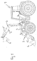
- Figure 1 shows a tractor 1 which has a front loader 2.
- the front loader comprises a boom 4 which carries a tool 6.
- a first pair of hydraulic cylinders 5 moves a tool 6, for example a bucket so that it pivots about a substantially horizontal axis.
- a second pair of hydraulic cylinders 3 lift and lower the boom 4.
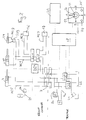
- Figure 2 shows a circuit diagram of the hydraulic circuits on the front loader when they are connected to the tractor's hydraulic circuit.
- the dashed line shows which parts are located on the tractor 1 and which parts are located on the front loader 2.
- the hydraulic cylinders 3, 5 are connected by a multicoupler 7 to two control valves CV1 and CV2 on the tractor.
- the control valves CV1 and CV2 are connected to a pump 23 and a fluid reserve 22 on the tractor.
- the control valves CV1, CV2 are connected to a tractor control unit 18 which is connected to a control means 10 and a terminal 20 in the tractor cab as shown by the dotted lines.
- the front loader may also be provided with its own control unit 26a which communicates with the tractor control unit 18.
- the control means 10 comprises a lever 11 with selector means 13,14, 24 and 25.
- Lever 11 is a cross gate lever which can be moved in four directions (forwards and backwards along axis A and left and right along axis B) about a central, neutral position.
- Selector means 13, 14 may be, for example buttons or switches which can be activated whilst the driver moves lever 11.
- Selector means 24, 25 are provided on the base of the control means 10 and may also be for example, buttons or switches.
- Terminal 20 displays various parameters associated with the tractor and front loader and allows various parameters, associated with the hydraulic circuits, such as fluid flow to be set.
- a first hydraulic circuit HC1 is connected to control valve CV1.
- the first hydraulic circuit HC1 comprises a first cylinder or first pair of cylinders 5.
- First cylinder 5 is used to move a tool attached to the front loader such as a bucket, or hay grab.
- a further consumer 8 such as a hydraulic cylinder on a trailed or mounted implement connected to the rear of the tractor may alternatively be connected to hydraulic circuit HC1 when the front loader is not being used.
- Consumer 8 is connected to circuit HC1 by circuit 8a. Since circuit 8a is only controlled by valve CV1 the fluid flow through it can only be changed if the fluid flow through circuit HC1 is changed.
- fluid flow it is meant the volume flow rate, that it the volume of fluid flowing through the circuit per unit time and also the amount of time the fluid is flowing through the circuit. The latter is controlled by how long an associated circuit valve is activated.
- first hydraulic circuit HC1 is connected to at least one further hydraulic circuit HC2 or HC3 by respective switch means, switch valves SV1, SV2. These switch valves are connected to the tractor control unit 18 and front loader control unit 26a if present. Switch valves SV1, SV2 may be integrated into one single valve.
- FIG 2 two further hydraulic circuits are shown, a second further hydraulic circuit HC2 and a third further hydraulic circuit HC3.
- Each further circuit HC2, HC3 is connected to HC1 circuit by respective switch valves SV1 and SV2.
- Circuits HC2 and HC3 are connected to consumers 16 and 17 respectively which may be needed, for example to control a grab bucket, or a bucket with a pivotable beater as described above. Further circuits could be connected to HC1 by further switch means.
- a fourth further hydraulic circuit HC4 is connected to a consumer or hydraulic cylinder 19 in parallel to first hydraulic circuit HC1.
- Circuit HC4 is provided with a switch valve SV3 which is connected to the control unit 18 and front loader control unit 26a if it is present.
- the hydraulic circuit HC4 may be used, for example to control an automatic locking means for connecting the boom 4 to the tool 6 to make attachment of the tool to the boom simple.
- An additional hydraulic circuit HC5 on the front loader comprises a hydraulic cylinder or pair of cylinders 3 connected to a second control valve CV2 on the tractor by a multicoupler 7. Hydraulic cylinder 3 is used to lift and lower the boom of the front loader.
- lever 11 When it is desired to move the boom up and down, lever 11 is moved along axis A which controls the hydraulic circuit HC5. Pushing the lever forwards lowers the boom and pulling the lever backwards raises the boom. Moving the lever along axis B controls hydraulic circuit HC1. Moving the lever left pivots the bucket upwards and moving the lever right pivots the bucket downwards. In this position switch valves SV1 and SV2 are in a position so that fluid flows from and to the fluid reserve 22 to cylinder 5 and switch valve SV3 is closed. By pressing button 13 and moving the lever along the B axis further hydraulic circuit HC2 is controlled. By pressing button 13 and moving the lever along axis B, the further circuit HC2 is activated.
- Button 13 controls switch valve SV1 so when it is pushed fluid flows to and from the fluid reserve 22 to consumer 16. By pressing button 14 and moving the lever along the B axis further hydraulic circuit HC3 is controlled. Button 14 controls switch valve SV2 so when it is pushed fluid flows to and from the fluid reserve 22 to consumer 17.
- control valve CV1 When button 13 is pressed on control means 10, control valve CV1 automatically moves to a set position at the same time as switch valve SV1 is switched. The same occurs for circuits HC3 and HC4 and switches SV2 and SV3 when the respective buttons 14 and 25 are pressed on control means 10, that is button 14 controls hydraulic circuit HC3 and button 25 controls hydraulic circuit HC4. This means that each circuit HC1, HC2, HC3 and HC4 can have its own fluid flow independent of the other circuits.
- control movements are in a first mode of operation of the lever 11 and allow the amount of movement of the hydraulic consumer or hydraulic cylinder of the respective hydraulic circuits HC1, HC2, HC3 and HC5 to be manually controlled by the driver by movement of the lever 11
- hydraulic circuit HC1 and hydraulic circuit HC4 are supplied in parallel.
- the locking means (not shown) is closed very fast, so supplying both the first cylinder 5 and consumer 19 at the same time does not cause any problems.
- a damping circuit 21 is connected to hydraulic circuit HC5 and controlled by control means 10 by pressing button 24.
- a second mode of operation which controls programmed sequences or functions associated with the hydraulic circuits HC1, HC2, HC3 and HC5, is activated by pushing button 32b (see Figure 4 ).
- this mode further hydraulic circuit HC3 cannot be controlled by lever 11.
- Movement along axis A in the second mode moves cylinder 3, the front loader to pre-determined positions which are described in more detail later.
- Movement of the lever to the right along axis B causes the bucket to shake by continuously pressurising and de-pressurising cylinder 5 automatically.
- Movement of the lever to the left in the second mode initiates a weighing process of the load carried by the front loader which is described later. Damping button 24 and locking button 25 are de-activated in the second mode.
- Consumer 8 and 9 are only supplied when the front loader is hydraulically disconnected from the supply system. These consumers 8, 9 are controlled by the settings of CV1 and CV2 respectively.
- control valves CV1 and CV2 can be entered into the terminal 20 for each of the circuits HC1, HC2, HC3, HC4 and HC5 which therefore affects the fluid flow through each circuit.
- the length of time switch valves SV1, SV2 and SV3 are activated for each circuit, as well as the volume flow rate of the fluid through each circuit can be set.
- the invention means that various hydraulic circuits associated with the front loader, or those associated with another implement attached to a tractor can be controlled by the same control means in the cab of a tractor and each circuit can be operated with its own fluid flow parameters suitable for the consumer concerned.
- the further hydraulic circuits HC2, HC3 and HC4 are connected to the first hydraulic circuit HC1 whilst hydraulic circuit HC5 has only one additional circuit 9a. It is also possible that either of the first hydraulic circuit HC1 or hydraulic circuit HC5 may be connected to any of the further circuits HC2, HC3, HC4.
- Figure 3 shows a screen shot of the image seen on the terminal by the driver when it is turned on.
- the screen is provided with a column of buttons or other selector means on the right hand side which relate to functions and parameters associated with the tractor.
- buttons or other selector means on the right hand side which relate to functions and parameters associated with the tractor.
- buttons 32a and 32b are associated with the first and second modes of the control means respectively.
- button 32a changes the function of button 13 on lever 11 from hydraulic circuit HC2 to hydraulic circuit HC4 to replace the function of button 25. This may be advantageous when tools have to be changed frequently and no additional consumer on the tool needs to be controlled by hydraulic circuit HC2.
- the top portion of the screen 27 shows the lever directions along the A and B axes in the first mode of operation and the corresponding movement of the tool or front loader. (Forwards and backwards for moving the loader up and down and left and right for pivoting the bucket.)
- the middle portion of the screen 28 allows the type of material to be carried in the tool to be selected from a drop down menu 29. More than one material can be stored in the terminal at one time. If, therefore the driver is carrying different materials throughout the day or week, the driver simply selects the material being currently carried and changes the mode on the control means to mode 2 and moves the lever to initiate the weighing process.
- the terminal will display the weight of that selected material in box 30.
- the terminal will also display the total weight of the selected material over a period of time in which more than one load of selected material has been carried. The total weight is shown in box 31.
- buttons 34a, 34b, 34c and 34d By selecting button 34, the screen as shown in figure 5 is displayed which shows the weight of 4 different materials in boxes 34a, 34b, 34c and 34d and the total weight of all these materials in boxes 35a and 35b for a given period of time and a given type of material. If the material is changed via drop down menu 29 shown in figure 4 , boxes 35a, 35b show the overall weight of the selected material. In addition, the driver can enter a target value for the overall weight in box 36, This overall weight represents the sum of all selected materials loaded during a given period of time. Alternatively, more than one box 31 may be provided to show the overall weight of various selected materials simultaneously. The weights of each material carried can be saved onto a USB stick by pressing button 37.
- the bottom portion of the screen 33 shows the current position of the front loader 36 and the current position of the tool 37.
- the current positions are shown as percentages 36a and 37a of the total movement of the associated hydraulic cylinder(s) which move the boom of the front loader and the tool respectively, as well as by shading upto the dotted lines. Alternatively, the percentages could reflect an amount of the total pivotal movement of the boom and an amount of the total pivotal movement of the bucket.
- the bottom portion also shows two stored positions of each of the front loader and bucket, displayed as triangles 38. The two positions indicate a higher and a lower position for each of the loader and the bucket. As described earlier the boom can be moved to one of these stored positions automatically by moving the lever in the second mode along axis A.
- markings 39 indicate the preferred range of where the loader and bucket should be carried, In this example, it is preferable that the loader and bucket are carried between 25% and 80% of their minimum and maximum positions. Again, this assists the driver in programming the stored positions and showing the current positions relative to this range.
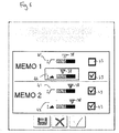
- pressing button 40 the driver is taken to a further screen figure 6 in which two stored positions can be entered for each of the loader and tool. The two positions for the loader 41 must be different and the two positions for the tool 42 must be different.
- any of the stored positions are not to be used during the second mode of operation of the lever along the A axis, they can be de-activated by deselecting the appropriate box 43 on the terminal. When these stored positions are de-selected, triangles 38 change colour. When the stored positions are to be used during the second mode of operation of the lever along the A axis, the stored positions are selected using boxes 43 on the terminal.
- the second mode is activated while hydraulic circuit HC 3 is deactivated.
- Terminal 20 displays parameters associated with the second mode.
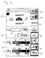
- button 32b is pressed, the driver is taken to the screen shown in figure 7 .
- the top portion of the screen shows the lever directions along n the A and B axes for the second mode of operation and the corresponding automated functions associated with the movements. Moving the lever in the A axis takes the loader to the first or second stored position 38. Moving the lever to the rights shakes the bucket so that any material stuck in the bucket can be emptied. Moving the lever to the left initiates the material weighing process. The remainder of the screen stays the same as in figure 4 .
- the minimum and maximum flow rates can be entered for circuit hydraulic HC5 by entering values along the line 48, for circuit HC1 by entering values along line 49, for hydraulic circuit HC2 by entering values along line 50 and for hydraulic circuit HC4 by entering values along line 51.
- the length of time the associated control valve is opened can be entered (as shown along line 50). Boxes 48a, 49a, 50a and 51 a show additional information relating to the valve settings.
- Lower portion 46 concerns the damping of the loader. Over rough ground it is necessary for hydraulic circuit HC5 to be dampened to prevent undue movement of the boom.
- Damping circuit 21 is controlled by button 53 on the terminal 20 which controls valve 21 a. The terminal allows the speed of the vehicle to be entered for when damping is to be automatically activated. The vehicle speed is entered in box 52 and the automatic damping function is activated by pressing button 53. Button 53 controls valve 21 a in damping circuit 21. Button 54 activates the end position damping for the hydraulic cylinders to avoid hard sticking of the cylinders when reaching their end position.
- the damping circuit 21 shown is placed in hydraulic circuit HC5 to dampen movement of the boom. A further damping circuit could be placed in hydraulic circuit HC1 to dampen movement of the tool.
- a further consumer 9 such as a hydraulic cylinder on a trailed or mounted implement connected to the rear of the tractor may be alternatively connected to the hydraulic circuit 3.
- Consumer 9 is connected to hydraulic circuit HC5 by hydraulic circuit 9a.
- the fluid flow through hydraulic HC5 is regulated by control valve CV2 which is controlled by control means 10 located in the tractor cab. Since circuit 9a is only controlled by valve CV2 the fluid flow through it can only be changed if the flow rate through circuit HC2 is changed.
- the further hydraulic circuits HC2, HC3 and HC4 are connected to the first hydraulic circuit HC1 whilst hydraulic circuit HC5 has only one additional circuit 9a. It is also possible that either of the first hydraulic circuit HC1 or hydraulic circuit HC5 may be connected to any of the further hydraulic circuits HC2, HC3, HC4.
- the invention may be applicable to any vehicle (not just a tractor) which can carry an implement and/or tool.
Landscapes
- Engineering & Computer Science (AREA)
- Mining & Mineral Resources (AREA)
- Civil Engineering (AREA)
- General Engineering & Computer Science (AREA)
- Structural Engineering (AREA)
- Operation Control Of Excavators (AREA)
Abstract
Description
- This invention relates to a control means on a vehicle for controlling movement of an implement attached to the vehicle. More specifically, the invention relates to a control means on a tractor for controlling an implement attached to the tractor.
- Agricultural vehicles are provided with driver operable control means inside the vehicle to control various functions on the vehicle. The control means is connected to a vehicle control unit.
- For example, agricultural tractors may be provided with a lever and a terminal to input and display various parameters associated with the tractor such as air pressure of the tyres and the speed of the vehicle. The terminal is used to display various parameters associated with the tractor so that the driver can view in an instance what is happening.
- An implement such as a front loader may be attached to the tractor and the hydraulic circuits on the loader connected to those on the tractor. Typically the front loader will have a first hydraulic circuit for moving a tool, for example a bucket attached to the loader and a second hydraulic circuit for controlling vertical movement of the boom of the loader and further circuits for moving further consumers associated with the tool.
- Tools requiring further circuits to move an associated part are, for example: a grab bucket provided with forks which can be raised and lowered relative to the bucket to tear silage out of a silage silo during loading. In such a case a further circuit would raise and lower the forks.
- Alternatively, a front loader may be provided with a bucket having a pivotable beater attached. In such a case the further hydraulic circuit would control pivotal movement of the beater support relative to the bucket whilst a yet further hydraulic circuit would control the rotary drive of the beater. This tool loosens compacted silage during loading prior to distribution as animal fodder.
- First and second hydraulic circuits are each attached to two control valves on the tractor and the further circuit is connected to either the first hydraulic circuit or the second hydraulic circuit. Since the control valves are connected to the tractor control unit, first and second hydraulic circuits can be easily controlled by the driver using the joystick. It is typical that movement of the joystick forwards and backwards causes the loader to move up and down and movement of the joystick left and right causes the tool to pivot. Buttons may be provided on the joystick to switch control between the first, second and further hydraulic circuits.
- If further programmed functions or sequences requiring these hydraulic circuits, for example shaking the tool to empty its load or weighing the load carried by the tool are to be controlled with the lever, additional buttons must be provided on or close to the joystick. These additional buttons are not necessary for operating a standard front loader and therefore a tractor fitted with a standard front loader would not have a joystick with the additional buttons. Therefore if control of further programmed functions associated with these hydraulic circuits is required with a standard front loader a further joystick must be fitted. This has cost and space implications.
- Whilst additional buttons could be fitted to the joystick, these take up space on the lever and can cause confusion for the driver.
- It is an aim of the present invention to alleviate some of the problems outlined above by providing a single vehicle control means having two modes of operation for manually controlling hydraulic circuits and controlling automated functions and/or sequences associated with the hydraulic circuits.
- In accordance with the present invention there is provided a vehicle control means as claimed in
claim 1. Preferred features of the invention are set out in the dependent claims. - The invention will now be described, by example only, with reference to the following drawings in which:
-
Figure 1 is side view of a tractor fitted with a front loader; -
Figure 2 is a circuit diagram showing the connection of the hydraulic circuits associated with the loader and the control means for controlling the loader in accordance with the present invention; -
Figures 3 to 8 are screen shots from a terminal showing various parameters associated with the front loader in accordance with preferred features of the invention. -
Figure 1 shows atractor 1 which has afront loader 2. The front loader comprises aboom 4 which carries a tool 6. A first pair ofhydraulic cylinders 5 moves a tool 6, for example a bucket so that it pivots about a substantially horizontal axis. A second pair ofhydraulic cylinders 3 lift and lower theboom 4. -
Figure 2 shows a circuit diagram of the hydraulic circuits on the front loader when they are connected to the tractor's hydraulic circuit. The dashed line shows which parts are located on thetractor 1 and which parts are located on thefront loader 2. - The
hydraulic cylinders multicoupler 7 to two control valves CV1 and CV2 on the tractor. The control valves CV1 and CV2 are connected to apump 23 and afluid reserve 22 on the tractor. The control valves CV1, CV2 are connected to atractor control unit 18 which is connected to a control means 10 and a terminal 20 in the tractor cab as shown by the dotted lines. The front loader may also be provided with itsown control unit 26a which communicates with thetractor control unit 18. The control means 10 comprises a lever 11 with selector means 13,14, 24 and 25. Lever 11 is a cross gate lever which can be moved in four directions (forwards and backwards along axis A and left and right along axis B) about a central, neutral position. Selector means 13, 14 may be, for example buttons or switches which can be activated whilst the driver moves lever 11. Selector means 24, 25 are provided on the base of the control means 10 and may also be for example, buttons or switches. Terminal 20 displays various parameters associated with the tractor and front loader and allows various parameters, associated with the hydraulic circuits, such as fluid flow to be set. - A first hydraulic circuit HC1 is connected to control valve CV1. The first hydraulic circuit HC1 comprises a first cylinder or first pair of
cylinders 5.First cylinder 5 is used to move a tool attached to the front loader such as a bucket, or hay grab. Afurther consumer 8 such as a hydraulic cylinder on a trailed or mounted implement connected to the rear of the tractor may alternatively be connected to hydraulic circuit HC1 when the front loader is not being used.Consumer 8 is connected to circuit HC1 by circuit 8a. Since circuit 8a is only controlled by valve CV1 the fluid flow through it can only be changed if the fluid flow through circuit HC1 is changed. - By fluid flow it is meant the volume flow rate, that it the volume of fluid flowing through the circuit per unit time and also the amount of time the fluid is flowing through the circuit. The latter is controlled by how long an associated circuit valve is activated.
- In accordance with the invention first hydraulic circuit HC1 is connected to at least one further hydraulic circuit HC2 or HC3 by respective switch means, switch valves SV1, SV2. These switch valves are connected to the
tractor control unit 18 and frontloader control unit 26a if present. Switch valves SV1, SV2 may be integrated into one single valve. - In
figure 2 , two further hydraulic circuits are shown, a second further hydraulic circuit HC2 and a third further hydraulic circuit HC3. Each further circuit HC2, HC3 is connected to HC1 circuit by respective switch valves SV1 and SV2. Circuits HC2 and HC3 are connected toconsumers 16 and 17 respectively which may be needed, for example to control a grab bucket, or a bucket with a pivotable beater as described above. Further circuits could be connected to HC1 by further switch means. - A fourth further hydraulic circuit HC4 is connected to a consumer or
hydraulic cylinder 19 in parallel to first hydraulic circuit HC1. Circuit HC4 is provided with a switch valve SV3 which is connected to thecontrol unit 18 and frontloader control unit 26a if it is present. The hydraulic circuit HC4 may be used, for example to control an automatic locking means for connecting theboom 4 to the tool 6 to make attachment of the tool to the boom simple. - An additional hydraulic circuit HC5 on the front loader comprises a hydraulic cylinder or pair of
cylinders 3 connected to a second control valve CV2 on the tractor by amulticoupler 7.Hydraulic cylinder 3 is used to lift and lower the boom of the front loader. - When it is desired to move the boom up and down, lever 11 is moved along axis A which controls the hydraulic circuit HC5. Pushing the lever forwards lowers the boom and pulling the lever backwards raises the boom. Moving the lever along axis B controls hydraulic circuit HC1. Moving the lever left pivots the bucket upwards and moving the lever right pivots the bucket downwards. In this position switch valves SV1 and SV2 are in a position so that fluid flows from and to the
fluid reserve 22 tocylinder 5 and switch valve SV3 is closed. By pressingbutton 13 and moving the lever along the B axis further hydraulic circuit HC2 is controlled. By pressingbutton 13 and moving the lever along axis B, the further circuit HC2 is activated.Button 13 controls switch valve SV1 so when it is pushed fluid flows to and from thefluid reserve 22 toconsumer 16. By pressingbutton 14 and moving the lever along the B axis further hydraulic circuit HC3 is controlled.Button 14 controls switch valve SV2 so when it is pushed fluid flows to and from thefluid reserve 22 to consumer 17. - When
button 13 is pressed on control means 10, control valve CV1 automatically moves to a set position at the same time as switch valve SV1 is switched. The same occurs for circuits HC3 and HC4 and switches SV2 and SV3 when therespective buttons button 14 controls hydraulic circuit HC3 andbutton 25 controls hydraulic circuit HC4.This means that each circuit HC1, HC2, HC3 and HC4 can have its own fluid flow independent of the other circuits. - These control movements are in a first mode of operation of the lever 11 and allow the amount of movement of the hydraulic consumer or hydraulic cylinder of the respective hydraulic circuits HC1, HC2, HC3 and HC5 to be manually controlled by the driver by movement of the lever 11
- To activate
hydraulic cylinder 19 using hydraulic circuit HC4,button 25 is pushed and thereby hydraulic circuit HC1 and hydraulic circuit HC4 are supplied in parallel. Ashydraulic cylinder 19 is smaller thancylinder 5 connected to HC1, the locking means (not shown) is closed very fast, so supplying both thefirst cylinder 5 andconsumer 19 at the same time does not cause any problems. - A damping
circuit 21 is connected to hydraulic circuit HC5 and controlled by control means 10 by pressing button 24. - A second mode of operation, which controls programmed sequences or functions associated with the hydraulic circuits HC1, HC2, HC3 and HC5, is activated by pushing
button 32b (seeFigure 4 ). In this mode further hydraulic circuit HC3 cannot be controlled by lever 11. Movement along axis A in the second mode movescylinder 3, the front loader to pre-determined positions which are described in more detail later. Movement of the lever to the right along axis B causes the bucket to shake by continuously pressurising andde-pressurising cylinder 5 automatically. Movement of the lever to the left in the second mode initiates a weighing process of the load carried by the front loader which is described later. Damping button 24 andlocking button 25 are de-activated in the second mode. -
Consumer 8 and 9 are only supplied when the front loader is hydraulically disconnected from the supply system. Theseconsumers 8, 9 are controlled by the settings of CV1 and CV2 respectively. - Various settings for control valves CV1 and CV2 can be entered into the terminal 20 for each of the circuits HC1, HC2, HC3, HC4 and HC5 which therefore affects the fluid flow through each circuit. The length of time switch valves SV1, SV2 and SV3 are activated for each circuit, as well as the volume flow rate of the fluid through each circuit can be set.
- The invention means that various hydraulic circuits associated with the front loader, or those associated with another implement attached to a tractor can be controlled by the same control means in the cab of a tractor and each circuit can be operated with its own fluid flow parameters suitable for the consumer concerned.
- In the shown embodiment the further hydraulic circuits HC2, HC3 and HC4 are connected to the first hydraulic circuit HC1 whilst hydraulic circuit HC5 has only one additional circuit 9a. It is also possible that either of the first hydraulic circuit HC1 or hydraulic circuit HC5 may be connected to any of the further circuits HC2, HC3, HC4.
-
Figure 3 shows a screen shot of the image seen on the terminal by the driver when it is turned on. The screen is provided with a column of buttons or other selector means on the right hand side which relate to functions and parameters associated with the tractor. By selecting thefront loader button 26, the driver is taken to the screen shot infigure 4 . (The other buttons are not described here since they do not relate to the present invention).Button 47 takes the driver back to the previously viewed screen. - On the front loader screen (as seen in
figure 4 )buttons 32a and 32b are associated with the first and second modes of the control means respectively. Infigure 4 , button 32a changes the function ofbutton 13 on lever 11 from hydraulic circuit HC2 to hydraulic circuit HC4 to replace the function ofbutton 25. This may be advantageous when tools have to be changed frequently and no additional consumer on the tool needs to be controlled by hydraulic circuit HC2. The top portion of thescreen 27 shows the lever directions along the A and B axes in the first mode of operation and the corresponding movement of the tool or front loader. (Forwards and backwards for moving the loader up and down and left and right for pivoting the bucket.) - The middle portion of the
screen 28 allows the type of material to be carried in the tool to be selected from a drop downmenu 29. More than one material can be stored in the terminal at one time. If, therefore the driver is carrying different materials throughout the day or week, the driver simply selects the material being currently carried and changes the mode on the control means tomode 2 and moves the lever to initiate the weighing process. The terminal will display the weight of that selected material inbox 30. The terminal will also display the total weight of the selected material over a period of time in which more than one load of selected material has been carried. The total weight is shown inbox 31. By selectingbutton 34, the screen as shown infigure 5 is displayed which shows the weight of 4 different materials inboxes boxes menu 29 shown infigure 4 ,boxes box 36, This overall weight represents the sum of all selected materials loaded during a given period of time. Alternatively, more than onebox 31 may be provided to show the overall weight of various selected materials simultaneously. The weights of each material carried can be saved onto a USB stick by pressingbutton 37. - Returning to
figure 4 the bottom portion of thescreen 33 shows the current position of thefront loader 36 and the current position of thetool 37. The current positions are shown aspercentages triangles 38. The two positions indicate a higher and a lower position for each of the loader and the bucket. As described earlier the boom can be moved to one of these stored positions automatically by moving the lever in the second mode along axis A. - The driver can easily see the current positions of the
boom 36a andbucket 37a relative to the storedpositions 38 on the terminal. Furthermore,markings 39 indicate the preferred range of where the loader and bucket should be carried, In this example, it is preferable that the loader and bucket are carried between 25% and 80% of their minimum and maximum positions. Again, this assists the driver in programming the stored positions and showing the current positions relative to this range. By pressingbutton 40 the driver is taken to a further screenfigure 6 in which two stored positions can be entered for each of the loader and tool. The two positions for theloader 41 must be different and the two positions for thetool 42 must be different. If any of the stored positions are not to be used during the second mode of operation of the lever along the A axis, they can be de-activated by deselecting theappropriate box 43 on the terminal. When these stored positions are de-selected,triangles 38 change colour. When the stored positions are to be used during the second mode of operation of the lever along the A axis, the stored positions are selected usingboxes 43 on the terminal. - Returning back to
figure 4 . Ifbutton 32b is pressed the second mode is activated whilehydraulic circuit HC 3 is deactivated. Terminal 20 displays parameters associated with the second mode. Ifbutton 32b is pressed, the driver is taken to the screen shown infigure 7 . Here the top portion of the screen shows the lever directions along n the A and B axes for the second mode of operation and the corresponding automated functions associated with the movements. Moving the lever in the A axis takes the loader to the first or second storedposition 38. Moving the lever to the rights shakes the bucket so that any material stuck in the bucket can be emptied. Moving the lever to the left initiates the material weighing process. The remainder of the screen stays the same as infigure 4 . - Returning to the screen shot in
figure 4 . Whenbutton 44 is pressed, the driver is taken to the screen shown infigure 8 . Infigure 8 the screen is divided into anupper portion 45 and alower portion 46.Upper portion 45 allows the driver to input fluid flow parameters for each of hydraulic circuits HC5, HC1, HC2 and HC3. - The minimum and maximum flow rates can be entered for circuit hydraulic HC5 by entering values along the
line 48, for circuit HC1 by entering values alongline 49, for hydraulic circuit HC2 by entering values alongline 50 and for hydraulic circuit HC4 by entering values alongline 51. The length of time the associated control valve is opened can be entered (as shown along line 50). Boxes 48a, 49a, 50a and 51 a show additional information relating to the valve settings. -
Lower portion 46 concerns the damping of the loader. Over rough ground it is necessary for hydraulic circuit HC5 to be dampened to prevent undue movement of the boom. Dampingcircuit 21 is controlled bybutton 53 on the terminal 20 which controls valve 21 a. The terminal allows the speed of the vehicle to be entered for when damping is to be automatically activated. The vehicle speed is entered inbox 52 and the automatic damping function is activated by pressingbutton 53.Button 53 controls valve 21 a in dampingcircuit 21.Button 54 activates the end position damping for the hydraulic cylinders to avoid hard sticking of the cylinders when reaching their end position. The dampingcircuit 21 shown is placed in hydraulic circuit HC5 to dampen movement of the boom. A further damping circuit could be placed in hydraulic circuit HC1 to dampen movement of the tool. - If the front loader is not being used a further consumer 9 such as a hydraulic cylinder on a trailed or mounted implement connected to the rear of the tractor may be alternatively connected to the
hydraulic circuit 3. Consumer 9 is connected to hydraulic circuit HC5 by hydraulic circuit 9a. The fluid flow through hydraulic HC5 is regulated by control valve CV2 which is controlled by control means 10 located in the tractor cab. Since circuit 9a is only controlled by valve CV2 the fluid flow through it can only be changed if the flow rate through circuit HC2 is changed. - In the shown embodiment the further hydraulic circuits HC2, HC3 and HC4 are connected to the first hydraulic circuit HC1 whilst hydraulic circuit HC5 has only one additional circuit 9a. It is also possible that either of the first hydraulic circuit HC1 or hydraulic circuit HC5 may be connected to any of the further hydraulic circuits HC2, HC3, HC4.
- In the shown embodiment a front loader and a tractor are described. Other implements, in particular a trailed or mounted implement also fall within the scope of the present invention. In this case, the hydraulic circuits HC1, HC2, HC3 and HC4 and respective consumers shown in
figure 2 would instead be installed on a trailed or mounted implement. - Furthermore, the invention may be applicable to any vehicle (not just a tractor) which can carry an implement and/or tool.
Claims (17)
- A vehicle control means for controlling movement of an implement attached to the vehicle having a first hydraulic circuit for moving the implement or a tool attached to the implement, a second hydraulic circuit for moving the tool or the implement and at least one further hydraulic circuit for moving an additional consumer relating to the tool or implement, said control means comprising a lever having a first and a second axis of operation wherein in a first mode of operation the first and the second axes of operation control manual movement of the first, second and the at least one further hydraulic circuits and wherein in a second mode of operation the first and second axes of operation control programmed functions associated with the first and second hydraulic circuits.
- A vehicle control means as claimed in claim 1 wherein in the first mode, movement of the lever along the first axis controls the first hydraulic circuit and movement of the lever along the second axis controls the second hydraulic circuit and activation of a first selector means whilst moving the lever along a first and/or second axis controls the at least one further circuit.
- A vehicle control means as claimed in claim 1 or claim 2 wherein in the second mode of operation, a second selector means is activated whilst the lever is moved and movement of the lever along the first axis moves the implement to a preprogrammed position, movement of the lever in one direction along the second axis continually pressurises and de-pressurises the first or second hydraulic circuit to shake the tool and movement of the lever in an opposite direction along the second axis initiates a weighing procedure of a load carried by the tool.
- A vehicle control means as claimed in any preceding claims wherein the control means comprises a terminal which displays the function of each lever movement for each of said first and second modes.
- A vehicle control means as claimed in claim 4 wherein at least one parameter relating to the position of the implement and/or at least one parameter relating to the position of the tool is stored in the terminal.
- A vehicle control means as claimed in 5 wherein a parameter relating to the current position and stored position of the implement and/or a parameter relating to the current position and stored position of the tool is displayed on the terminal.
- A vehicle control means as claimed in claim 5 or claim 6 wherein parameters relating to two positions of the implement and/or two positions of the tool are displayed in the terminal.
- A vehicle control means as claimed in any of claims 5 to 7 wherein the control means moves the implement and/or tool to the stored positions.
- A vehicle control means as claimed in any of claims 5 to 8 wherein the stored position of the implement and/or tool is activated or deactivated on the terminal.
- A vehicle control means as claimed-in any of claims 5 to 8 wherein the parameter relating to the position of the tool or implement is a percentage of the total movement of the respective hydraulic cylinder.
- A vehicle control means as claimed in any preceding claim wherein the terminal is provided with a function for continuously pressurising and de-pressurising the first hydraulic or second hydraulic circuit to empty material from the tool by shaking.
- A vehicle control means as claimed in any preceding claim wherein the control means calculates the weight of material carried by the tool.
- A vehicle control means as claimed in any preceding claim wherein the type of material carried by the tool is selected from a drop down list on the terminal and the terminal displays the total weight of material carried for the selected material.
- A vehicle control means as claimed in claim 12 wherein the weight of more than one material is stored and displayed on the terminal.
- A vehicle control means as claimed in any of claims 12 to 14 wherein the stored weight of the material can be saved to an external and transportable means via an interface.
- A vehicle control means as claimed in any preceding claim wherein the implement is a front loader.
- A vehicle control means as claimed in any preceding claim where the vehicle is a tractor.
Applications Claiming Priority (1)
| Application Number | Priority Date | Filing Date | Title |
|---|---|---|---|
| GB201113697A GB201113697D0 (en) | 2011-08-09 | 2011-08-09 | Control means for controlling an implement attached to a vehicle |
Publications (2)
| Publication Number | Publication Date |
|---|---|
| EP2557238A1 true EP2557238A1 (en) | 2013-02-13 |
| EP2557238B1 EP2557238B1 (en) | 2018-07-18 |
Family
ID=44735645
Family Applications (2)
| Application Number | Title | Priority Date | Filing Date |
|---|---|---|---|
| EP12177045A Withdrawn EP2557236A1 (en) | 2011-08-09 | 2012-07-19 | Control valve for controlling an implement attached to a vehicle |
| EP12178588.5A Active EP2557238B1 (en) | 2011-08-09 | 2012-07-31 | Control means for controlling an implement attached to a vehicle |
Family Applications Before (1)
| Application Number | Title | Priority Date | Filing Date |
|---|---|---|---|
| EP12177045A Withdrawn EP2557236A1 (en) | 2011-08-09 | 2012-07-19 | Control valve for controlling an implement attached to a vehicle |
Country Status (2)
| Country | Link |
|---|---|
| EP (2) | EP2557236A1 (en) |
| GB (2) | GB201113697D0 (en) |
Cited By (4)
| Publication number | Priority date | Publication date | Assignee | Title |
|---|---|---|---|---|
| EP2987672A1 (en) * | 2014-08-19 | 2016-02-24 | Kubota Corporation | Operation control system |
| US20190184827A1 (en) * | 2017-12-20 | 2019-06-20 | Agco International Gmbh | Agricultural vehicle |
| US10597845B2 (en) | 2017-09-27 | 2020-03-24 | Deere & Company | Implement vibration system and method |
| US11052760B2 (en) | 2017-12-20 | 2021-07-06 | Agco International Gmbh | Agricultural vehicle |
Families Citing this family (1)
| Publication number | Priority date | Publication date | Assignee | Title |
|---|---|---|---|---|
| IT202300004440A1 (en) * | 2023-03-09 | 2024-09-09 | Cnh Ind Italia Spa | IMPROVED SYSTEM AND METHOD FOR CONTROLLING A FRONT LOADER OF A WORK VEHICLE |
Citations (8)
| Publication number | Priority date | Publication date | Assignee | Title |
|---|---|---|---|---|
| WO2000036250A1 (en) * | 1998-12-15 | 2000-06-22 | Bombardier Inc. | Snow groomers and control system therefor |
| US6757992B1 (en) * | 2003-01-14 | 2004-07-06 | New Holland North America, Inc. | Skid steer loader bucket shaker |
| US20050085929A1 (en) * | 2003-10-16 | 2005-04-21 | Caterpillar Inc. | Operator interface for a work machine |
| US20060137931A1 (en) * | 2004-12-23 | 2006-06-29 | Caterpillar Inc. | Steering system with joystick mounted controls |
| EP1889537A2 (en) * | 2006-08-16 | 2008-02-20 | John Deere Forestry Oy | Control of a boom construction and a tool articulated thereto |
| EP2028320A1 (en) * | 2007-08-20 | 2009-02-25 | JCB Compact Products Limited | Method of controlling a working machine |
| US20090127031A1 (en) * | 2007-10-23 | 2009-05-21 | Paul John Corder | Weight Calculation Compensation |
| US7681686B1 (en) * | 2006-09-14 | 2010-03-23 | Deere & Company | Operator control for simultaneous movement of a multifunction machine |
Family Cites Families (6)
| Publication number | Priority date | Publication date | Assignee | Title |
|---|---|---|---|---|
| US5235809A (en) * | 1991-09-09 | 1993-08-17 | Vickers, Incorporated | Hydraulic circuit for shaking a bucket on a vehicle |
| US6725105B2 (en) * | 2000-11-30 | 2004-04-20 | Caterpillar Inc | Bucket shakeout mechanism for electro-hydraulic machines |
| US6763661B2 (en) * | 2002-05-07 | 2004-07-20 | Husco International, Inc. | Apparatus and method for providing vibration to an appendage of a work vehicle |
| SE526989C2 (en) * | 2004-04-19 | 2005-11-29 | Volvo Constr Equip Holding Se | Method for shaking work tools |
| US7467514B2 (en) * | 2006-07-17 | 2008-12-23 | Caterpillar Inc. | System and method for controlling shakability of a work tool |
| US7726125B2 (en) * | 2007-07-31 | 2010-06-01 | Caterpillar Inc. | Hydraulic circuit for rapid bucket shake out |
-
2011
- 2011-08-09 GB GB201113697A patent/GB201113697D0/en not_active Ceased
- 2011-11-17 GB GB201119855A patent/GB201119855D0/en not_active Ceased
-
2012
- 2012-07-19 EP EP12177045A patent/EP2557236A1/en not_active Withdrawn
- 2012-07-31 EP EP12178588.5A patent/EP2557238B1/en active Active
Patent Citations (8)
| Publication number | Priority date | Publication date | Assignee | Title |
|---|---|---|---|---|
| WO2000036250A1 (en) * | 1998-12-15 | 2000-06-22 | Bombardier Inc. | Snow groomers and control system therefor |
| US6757992B1 (en) * | 2003-01-14 | 2004-07-06 | New Holland North America, Inc. | Skid steer loader bucket shaker |
| US20050085929A1 (en) * | 2003-10-16 | 2005-04-21 | Caterpillar Inc. | Operator interface for a work machine |
| US20060137931A1 (en) * | 2004-12-23 | 2006-06-29 | Caterpillar Inc. | Steering system with joystick mounted controls |
| EP1889537A2 (en) * | 2006-08-16 | 2008-02-20 | John Deere Forestry Oy | Control of a boom construction and a tool articulated thereto |
| US7681686B1 (en) * | 2006-09-14 | 2010-03-23 | Deere & Company | Operator control for simultaneous movement of a multifunction machine |
| EP2028320A1 (en) * | 2007-08-20 | 2009-02-25 | JCB Compact Products Limited | Method of controlling a working machine |
| US20090127031A1 (en) * | 2007-10-23 | 2009-05-21 | Paul John Corder | Weight Calculation Compensation |
Cited By (8)
| Publication number | Priority date | Publication date | Assignee | Title |
|---|---|---|---|---|
| EP2987672A1 (en) * | 2014-08-19 | 2016-02-24 | Kubota Corporation | Operation control system |
| JP2016041565A (en) * | 2014-08-19 | 2016-03-31 | 株式会社クボタ | Operation control system |
| US9670939B2 (en) | 2014-08-19 | 2017-06-06 | Kubota Corporation | Operation control system |
| US10597845B2 (en) | 2017-09-27 | 2020-03-24 | Deere & Company | Implement vibration system and method |
| US20190184827A1 (en) * | 2017-12-20 | 2019-06-20 | Agco International Gmbh | Agricultural vehicle |
| EP3502359A1 (en) * | 2017-12-20 | 2019-06-26 | AGCO International GmbH | Agricultural vehicle |
| US10821830B2 (en) * | 2017-12-20 | 2020-11-03 | Agco International Gmbh | Agricultural vehicle |
| US11052760B2 (en) | 2017-12-20 | 2021-07-06 | Agco International Gmbh | Agricultural vehicle |
Also Published As
| Publication number | Publication date |
|---|---|
| GB201119855D0 (en) | 2011-12-28 |
| GB201113697D0 (en) | 2011-09-21 |
| EP2557236A1 (en) | 2013-02-13 |
| EP2557238B1 (en) | 2018-07-18 |
Similar Documents
| Publication | Publication Date | Title |
|---|---|---|
| EP2557238B1 (en) | Control means for controlling an implement attached to a vehicle | |
| US10246855B2 (en) | Material handling machine with bucket shake control system and method | |
| US10145085B2 (en) | Working machine and control system | |
| EP3556945B1 (en) | Construction machine | |
| CN207750301U (en) | Dual Mode Control System for Work Vehicles | |
| US10047495B2 (en) | Loader control system and loader control method | |
| KR102029109B1 (en) | Operation support device of working machine | |
| EP3114284B1 (en) | Working machine with return-to-dig functionality | |
| KR20220037440A (en) | shovel | |
| CN111823856B (en) | System and method for controlling a work vehicle | |
| CN111287230A (en) | Attachment configurable system for a work machine | |
| WO2013020856A2 (en) | Implement for attachment to a vehicle | |
| EP3584374B1 (en) | Work vehicle | |
| AU2019280826B2 (en) | Face shovel and method of operation | |
| CN113529831B (en) | Improved hydraulic arrangement | |
| EP2556737A1 (en) | Control means for controlling damping of an implement attached to a vehicle | |
| US20060263189A1 (en) | System and a method for moving an implement of a vehicle | |
| US20250024769A1 (en) | Agricultural Vehicle with a Working Component and a Method for Controlling the Working Component | |
| JP5900210B2 (en) | Rice transplanter | |
| JP2010190368A (en) | Hydraulic control device of construction machine | |
| EP2955285B1 (en) | A material handling machine | |
| US20240306526A1 (en) | Working machine and method of controlling working machine | |
| RU2452818C2 (en) | Damping system, working machine with said system and method of machine working tool damping in motion | |
| KR20240038591A (en) | Method for controlling work in agricultural tractor | |
| WO2025057812A1 (en) | Work machine |
Legal Events
| Date | Code | Title | Description |
|---|---|---|---|
| PUAI | Public reference made under article 153(3) epc to a published international application that has entered the european phase |
Free format text: ORIGINAL CODE: 0009012 |
|
| AK | Designated contracting states |
Kind code of ref document: A1 Designated state(s): AL AT BE BG CH CY CZ DE DK EE ES FI FR GB GR HR HU IE IS IT LI LT LU LV MC MK MT NL NO PL PT RO RS SE SI SK SM TR |
|
| AX | Request for extension of the european patent |
Extension state: BA ME |
|
| 17P | Request for examination filed |
Effective date: 20130813 |
|
| RBV | Designated contracting states (corrected) |
Designated state(s): AL AT BE BG CH CY CZ DE DK EE ES FI FR GB GR HR HU IE IS IT LI LT LU LV MC MK MT NL NO PL PT RO RS SE SI SK SM TR |
|
| REG | Reference to a national code |
Ref country code: DE Ref legal event code: R079 Ref document number: 602012048545 Country of ref document: DE Free format text: PREVIOUS MAIN CLASS: E02F0009200000 Ipc: E02F0009220000 |
|
| RIC1 | Information provided on ipc code assigned before grant |
Ipc: E02F 9/22 20060101AFI20171020BHEP Ipc: E02F 9/26 20060101ALI20171020BHEP Ipc: E02F 9/20 20060101ALI20171020BHEP |
|
| GRAP | Despatch of communication of intention to grant a patent |
Free format text: ORIGINAL CODE: EPIDOSNIGR1 |
|
| STAA | Information on the status of an ep patent application or granted ep patent |
Free format text: STATUS: GRANT OF PATENT IS INTENDED |
|
| INTG | Intention to grant announced |
Effective date: 20180209 |
|
| GRAS | Grant fee paid |
Free format text: ORIGINAL CODE: EPIDOSNIGR3 |
|
| GRAA | (expected) grant |
Free format text: ORIGINAL CODE: 0009210 |
|
| STAA | Information on the status of an ep patent application or granted ep patent |
Free format text: STATUS: THE PATENT HAS BEEN GRANTED |
|
| AK | Designated contracting states |
Kind code of ref document: B1 Designated state(s): AL AT BE BG CH CY CZ DE DK EE ES FI FR GB GR HR HU IE IS IT LI LT LU LV MC MK MT NL NO PL PT RO RS SE SI SK SM TR |
|
| REG | Reference to a national code |
Ref country code: GB Ref legal event code: FG4D |
|
| REG | Reference to a national code |
Ref country code: FR Ref legal event code: PLFP Year of fee payment: 7 |
|
| REG | Reference to a national code |
Ref country code: CH Ref legal event code: EP |
|
| REG | Reference to a national code |
Ref country code: IE Ref legal event code: FG4D |
|
| REG | Reference to a national code |
Ref country code: AT Ref legal event code: REF Ref document number: 1019514 Country of ref document: AT Kind code of ref document: T Effective date: 20180815 |
|
| REG | Reference to a national code |
Ref country code: DE Ref legal event code: R096 Ref document number: 602012048545 Country of ref document: DE |
|
| REG | Reference to a national code |
Ref country code: NL Ref legal event code: MP Effective date: 20180718 |
|
| PGFP | Annual fee paid to national office [announced via postgrant information from national office to epo] |
Ref country code: GB Payment date: 20180822 Year of fee payment: 7 |
|
| REG | Reference to a national code |
Ref country code: LT Ref legal event code: MG4D |
|
| REG | Reference to a national code |
Ref country code: AT Ref legal event code: MK05 Ref document number: 1019514 Country of ref document: AT Kind code of ref document: T Effective date: 20180718 |
|
| PG25 | Lapsed in a contracting state [announced via postgrant information from national office to epo] |
Ref country code: NL Free format text: LAPSE BECAUSE OF FAILURE TO SUBMIT A TRANSLATION OF THE DESCRIPTION OR TO PAY THE FEE WITHIN THE PRESCRIBED TIME-LIMIT Effective date: 20180718 |
|
| PG25 | Lapsed in a contracting state [announced via postgrant information from national office to epo] |
Ref country code: PL Free format text: LAPSE BECAUSE OF FAILURE TO SUBMIT A TRANSLATION OF THE DESCRIPTION OR TO PAY THE FEE WITHIN THE PRESCRIBED TIME-LIMIT Effective date: 20180718 Ref country code: IS Free format text: LAPSE BECAUSE OF FAILURE TO SUBMIT A TRANSLATION OF THE DESCRIPTION OR TO PAY THE FEE WITHIN THE PRESCRIBED TIME-LIMIT Effective date: 20181118 Ref country code: RS Free format text: LAPSE BECAUSE OF FAILURE TO SUBMIT A TRANSLATION OF THE DESCRIPTION OR TO PAY THE FEE WITHIN THE PRESCRIBED TIME-LIMIT Effective date: 20180718 Ref country code: LT Free format text: LAPSE BECAUSE OF FAILURE TO SUBMIT A TRANSLATION OF THE DESCRIPTION OR TO PAY THE FEE WITHIN THE PRESCRIBED TIME-LIMIT Effective date: 20180718 Ref country code: SE Free format text: LAPSE BECAUSE OF FAILURE TO SUBMIT A TRANSLATION OF THE DESCRIPTION OR TO PAY THE FEE WITHIN THE PRESCRIBED TIME-LIMIT Effective date: 20180718 Ref country code: BG Free format text: LAPSE BECAUSE OF FAILURE TO SUBMIT A TRANSLATION OF THE DESCRIPTION OR TO PAY THE FEE WITHIN THE PRESCRIBED TIME-LIMIT Effective date: 20181018 Ref country code: FI Free format text: LAPSE BECAUSE OF FAILURE TO SUBMIT A TRANSLATION OF THE DESCRIPTION OR TO PAY THE FEE WITHIN THE PRESCRIBED TIME-LIMIT Effective date: 20180718 Ref country code: GR Free format text: LAPSE BECAUSE OF FAILURE TO SUBMIT A TRANSLATION OF THE DESCRIPTION OR TO PAY THE FEE WITHIN THE PRESCRIBED TIME-LIMIT Effective date: 20181019 Ref country code: AT Free format text: LAPSE BECAUSE OF FAILURE TO SUBMIT A TRANSLATION OF THE DESCRIPTION OR TO PAY THE FEE WITHIN THE PRESCRIBED TIME-LIMIT Effective date: 20180718 Ref country code: NO Free format text: LAPSE BECAUSE OF FAILURE TO SUBMIT A TRANSLATION OF THE DESCRIPTION OR TO PAY THE FEE WITHIN THE PRESCRIBED TIME-LIMIT Effective date: 20181018 |
|
| PG25 | Lapsed in a contracting state [announced via postgrant information from national office to epo] |
Ref country code: LV Free format text: LAPSE BECAUSE OF FAILURE TO SUBMIT A TRANSLATION OF THE DESCRIPTION OR TO PAY THE FEE WITHIN THE PRESCRIBED TIME-LIMIT Effective date: 20180718 Ref country code: HR Free format text: LAPSE BECAUSE OF FAILURE TO SUBMIT A TRANSLATION OF THE DESCRIPTION OR TO PAY THE FEE WITHIN THE PRESCRIBED TIME-LIMIT Effective date: 20180718 Ref country code: AL Free format text: LAPSE BECAUSE OF FAILURE TO SUBMIT A TRANSLATION OF THE DESCRIPTION OR TO PAY THE FEE WITHIN THE PRESCRIBED TIME-LIMIT Effective date: 20180718 |
|
| REG | Reference to a national code |
Ref country code: CH Ref legal event code: PL |
|
| PG25 | Lapsed in a contracting state [announced via postgrant information from national office to epo] |
Ref country code: LU Free format text: LAPSE BECAUSE OF NON-PAYMENT OF DUE FEES Effective date: 20180731 |
|
| REG | Reference to a national code |
Ref country code: BE Ref legal event code: MM Effective date: 20180731 |
|
| REG | Reference to a national code |
Ref country code: DE Ref legal event code: R097 Ref document number: 602012048545 Country of ref document: DE |
|
| PG25 | Lapsed in a contracting state [announced via postgrant information from national office to epo] |
Ref country code: ES Free format text: LAPSE BECAUSE OF FAILURE TO SUBMIT A TRANSLATION OF THE DESCRIPTION OR TO PAY THE FEE WITHIN THE PRESCRIBED TIME-LIMIT Effective date: 20180718 Ref country code: EE Free format text: LAPSE BECAUSE OF FAILURE TO SUBMIT A TRANSLATION OF THE DESCRIPTION OR TO PAY THE FEE WITHIN THE PRESCRIBED TIME-LIMIT Effective date: 20180718 Ref country code: RO Free format text: LAPSE BECAUSE OF FAILURE TO SUBMIT A TRANSLATION OF THE DESCRIPTION OR TO PAY THE FEE WITHIN THE PRESCRIBED TIME-LIMIT Effective date: 20180718 Ref country code: CH Free format text: LAPSE BECAUSE OF NON-PAYMENT OF DUE FEES Effective date: 20180731 Ref country code: IT Free format text: LAPSE BECAUSE OF FAILURE TO SUBMIT A TRANSLATION OF THE DESCRIPTION OR TO PAY THE FEE WITHIN THE PRESCRIBED TIME-LIMIT Effective date: 20180718 Ref country code: LI Free format text: LAPSE BECAUSE OF NON-PAYMENT OF DUE FEES Effective date: 20180731 Ref country code: MC Free format text: LAPSE BECAUSE OF FAILURE TO SUBMIT A TRANSLATION OF THE DESCRIPTION OR TO PAY THE FEE WITHIN THE PRESCRIBED TIME-LIMIT Effective date: 20180718 |
|
| REG | Reference to a national code |
Ref country code: IE Ref legal event code: MM4A |
|
| PLBE | No opposition filed within time limit |
Free format text: ORIGINAL CODE: 0009261 |
|
| STAA | Information on the status of an ep patent application or granted ep patent |
Free format text: STATUS: NO OPPOSITION FILED WITHIN TIME LIMIT |
|
| PG25 | Lapsed in a contracting state [announced via postgrant information from national office to epo] |
Ref country code: SM Free format text: LAPSE BECAUSE OF FAILURE TO SUBMIT A TRANSLATION OF THE DESCRIPTION OR TO PAY THE FEE WITHIN THE PRESCRIBED TIME-LIMIT Effective date: 20180718 Ref country code: SK Free format text: LAPSE BECAUSE OF FAILURE TO SUBMIT A TRANSLATION OF THE DESCRIPTION OR TO PAY THE FEE WITHIN THE PRESCRIBED TIME-LIMIT Effective date: 20180718 Ref country code: BE Free format text: LAPSE BECAUSE OF NON-PAYMENT OF DUE FEES Effective date: 20180731 Ref country code: DK Free format text: LAPSE BECAUSE OF FAILURE TO SUBMIT A TRANSLATION OF THE DESCRIPTION OR TO PAY THE FEE WITHIN THE PRESCRIBED TIME-LIMIT Effective date: 20180718 |
|
| 26N | No opposition filed |
Effective date: 20190423 |
|
| PG25 | Lapsed in a contracting state [announced via postgrant information from national office to epo] |
Ref country code: IE Free format text: LAPSE BECAUSE OF NON-PAYMENT OF DUE FEES Effective date: 20180731 |
|
| PG25 | Lapsed in a contracting state [announced via postgrant information from national office to epo] |
Ref country code: SI Free format text: LAPSE BECAUSE OF FAILURE TO SUBMIT A TRANSLATION OF THE DESCRIPTION OR TO PAY THE FEE WITHIN THE PRESCRIBED TIME-LIMIT Effective date: 20180718 |
|
| PG25 | Lapsed in a contracting state [announced via postgrant information from national office to epo] |
Ref country code: MT Free format text: LAPSE BECAUSE OF NON-PAYMENT OF DUE FEES Effective date: 20180731 |
|
| GBPC | Gb: european patent ceased through non-payment of renewal fee |
Effective date: 20190731 |
|
| PG25 | Lapsed in a contracting state [announced via postgrant information from national office to epo] |
Ref country code: TR Free format text: LAPSE BECAUSE OF FAILURE TO SUBMIT A TRANSLATION OF THE DESCRIPTION OR TO PAY THE FEE WITHIN THE PRESCRIBED TIME-LIMIT Effective date: 20180718 |
|
| PG25 | Lapsed in a contracting state [announced via postgrant information from national office to epo] |
Ref country code: GB Free format text: LAPSE BECAUSE OF NON-PAYMENT OF DUE FEES Effective date: 20190731 |
|
| PG25 | Lapsed in a contracting state [announced via postgrant information from national office to epo] |
Ref country code: HU Free format text: LAPSE BECAUSE OF FAILURE TO SUBMIT A TRANSLATION OF THE DESCRIPTION OR TO PAY THE FEE WITHIN THE PRESCRIBED TIME-LIMIT; INVALID AB INITIO Effective date: 20120731 Ref country code: PT Free format text: LAPSE BECAUSE OF FAILURE TO SUBMIT A TRANSLATION OF THE DESCRIPTION OR TO PAY THE FEE WITHIN THE PRESCRIBED TIME-LIMIT Effective date: 20180718 |
|
| PG25 | Lapsed in a contracting state [announced via postgrant information from national office to epo] |
Ref country code: MK Free format text: LAPSE BECAUSE OF NON-PAYMENT OF DUE FEES Effective date: 20180718 Ref country code: CY Free format text: LAPSE BECAUSE OF FAILURE TO SUBMIT A TRANSLATION OF THE DESCRIPTION OR TO PAY THE FEE WITHIN THE PRESCRIBED TIME-LIMIT Effective date: 20180718 |
|
| PGFP | Annual fee paid to national office [announced via postgrant information from national office to epo] |
Ref country code: CZ Payment date: 20210723 Year of fee payment: 10 |
|
| PG25 | Lapsed in a contracting state [announced via postgrant information from national office to epo] |
Ref country code: CZ Free format text: LAPSE BECAUSE OF NON-PAYMENT OF DUE FEES Effective date: 20220731 |
|
| P01 | Opt-out of the competence of the unified patent court (upc) registered |
Effective date: 20230518 |
|
| PGFP | Annual fee paid to national office [announced via postgrant information from national office to epo] |
Ref country code: DE Payment date: 20250722 Year of fee payment: 14 |
|
| PGFP | Annual fee paid to national office [announced via postgrant information from national office to epo] |
Ref country code: FR Payment date: 20250725 Year of fee payment: 14 |