EP2556558B1 - Interconnect joint - Google Patents
Interconnect joint Download PDFInfo
- Publication number
- EP2556558B1 EP2556558B1 EP11712390.1A EP11712390A EP2556558B1 EP 2556558 B1 EP2556558 B1 EP 2556558B1 EP 11712390 A EP11712390 A EP 11712390A EP 2556558 B1 EP2556558 B1 EP 2556558B1
- Authority
- EP
- European Patent Office
- Prior art keywords
- positive
- negative
- mandrel
- electrode
- electrode assembly
- Prior art date
- Legal status (The legal status is an assumption and is not a legal conclusion. Google has not performed a legal analysis and makes no representation as to the accuracy of the status listed.)
- Active
Links
Images




Classifications
-
- H—ELECTRICITY
- H01—ELECTRIC ELEMENTS
- H01M—PROCESSES OR MEANS, e.g. BATTERIES, FOR THE DIRECT CONVERSION OF CHEMICAL ENERGY INTO ELECTRICAL ENERGY
- H01M10/00—Secondary cells; Manufacture thereof
- H01M10/04—Construction or manufacture in general
- H01M10/0431—Cells with wound or folded electrodes
-
- H—ELECTRICITY
- H01—ELECTRIC ELEMENTS
- H01M—PROCESSES OR MEANS, e.g. BATTERIES, FOR THE DIRECT CONVERSION OF CHEMICAL ENERGY INTO ELECTRICAL ENERGY
- H01M10/00—Secondary cells; Manufacture thereof
- H01M10/05—Accumulators with non-aqueous electrolyte
- H01M10/058—Construction or manufacture
- H01M10/0587—Construction or manufacture of accumulators having only wound construction elements, i.e. wound positive electrodes, wound negative electrodes and wound separators
-
- H—ELECTRICITY
- H01—ELECTRIC ELEMENTS
- H01M—PROCESSES OR MEANS, e.g. BATTERIES, FOR THE DIRECT CONVERSION OF CHEMICAL ENERGY INTO ELECTRICAL ENERGY
- H01M10/00—Secondary cells; Manufacture thereof
- H01M10/24—Alkaline accumulators
- H01M10/28—Construction or manufacture
- H01M10/286—Cells or batteries with wound or folded electrodes
-
- H—ELECTRICITY
- H01—ELECTRIC ELEMENTS
- H01M—PROCESSES OR MEANS, e.g. BATTERIES, FOR THE DIRECT CONVERSION OF CHEMICAL ENERGY INTO ELECTRICAL ENERGY
- H01M10/00—Secondary cells; Manufacture thereof
- H01M10/24—Alkaline accumulators
- H01M10/28—Construction or manufacture
- H01M10/287—Small-sized flat cells or batteries for portable equipment
-
- H—ELECTRICITY
- H01—ELECTRIC ELEMENTS
- H01M—PROCESSES OR MEANS, e.g. BATTERIES, FOR THE DIRECT CONVERSION OF CHEMICAL ENERGY INTO ELECTRICAL ENERGY
- H01M10/00—Secondary cells; Manufacture thereof
- H01M10/24—Alkaline accumulators
- H01M10/28—Construction or manufacture
- H01M10/288—Processes for forming or storing electrodes in the battery container
-
- H—ELECTRICITY
- H01—ELECTRIC ELEMENTS
- H01M—PROCESSES OR MEANS, e.g. BATTERIES, FOR THE DIRECT CONVERSION OF CHEMICAL ENERGY INTO ELECTRICAL ENERGY
- H01M10/00—Secondary cells; Manufacture thereof
- H01M10/36—Accumulators not provided for in groups H01M10/05-H01M10/34
- H01M10/38—Construction or manufacture
-
- H—ELECTRICITY
- H01—ELECTRIC ELEMENTS
- H01M—PROCESSES OR MEANS, e.g. BATTERIES, FOR THE DIRECT CONVERSION OF CHEMICAL ENERGY INTO ELECTRICAL ENERGY
- H01M4/00—Electrodes
- H01M4/02—Electrodes composed of, or comprising, active material
- H01M4/04—Processes of manufacture in general
-
- Y—GENERAL TAGGING OF NEW TECHNOLOGICAL DEVELOPMENTS; GENERAL TAGGING OF CROSS-SECTIONAL TECHNOLOGIES SPANNING OVER SEVERAL SECTIONS OF THE IPC; TECHNICAL SUBJECTS COVERED BY FORMER USPC CROSS-REFERENCE ART COLLECTIONS [XRACs] AND DIGESTS
- Y02—TECHNOLOGIES OR APPLICATIONS FOR MITIGATION OR ADAPTATION AGAINST CLIMATE CHANGE
- Y02E—REDUCTION OF GREENHOUSE GAS [GHG] EMISSIONS, RELATED TO ENERGY GENERATION, TRANSMISSION OR DISTRIBUTION
- Y02E60/00—Enabling technologies; Technologies with a potential or indirect contribution to GHG emissions mitigation
- Y02E60/10—Energy storage using batteries
-
- Y—GENERAL TAGGING OF NEW TECHNOLOGICAL DEVELOPMENTS; GENERAL TAGGING OF CROSS-SECTIONAL TECHNOLOGIES SPANNING OVER SEVERAL SECTIONS OF THE IPC; TECHNICAL SUBJECTS COVERED BY FORMER USPC CROSS-REFERENCE ART COLLECTIONS [XRACs] AND DIGESTS
- Y02—TECHNOLOGIES OR APPLICATIONS FOR MITIGATION OR ADAPTATION AGAINST CLIMATE CHANGE
- Y02P—CLIMATE CHANGE MITIGATION TECHNOLOGIES IN THE PRODUCTION OR PROCESSING OF GOODS
- Y02P70/00—Climate change mitigation technologies in the production process for final industrial or consumer products
- Y02P70/50—Manufacturing or production processes characterised by the final manufactured product
-
- Y—GENERAL TAGGING OF NEW TECHNOLOGICAL DEVELOPMENTS; GENERAL TAGGING OF CROSS-SECTIONAL TECHNOLOGIES SPANNING OVER SEVERAL SECTIONS OF THE IPC; TECHNICAL SUBJECTS COVERED BY FORMER USPC CROSS-REFERENCE ART COLLECTIONS [XRACs] AND DIGESTS
- Y10—TECHNICAL SUBJECTS COVERED BY FORMER USPC
- Y10T—TECHNICAL SUBJECTS COVERED BY FORMER US CLASSIFICATION
- Y10T29/00—Metal working
- Y10T29/49—Method of mechanical manufacture
- Y10T29/49002—Electrical device making
- Y10T29/49108—Electric battery cell making
Definitions
- the invention relates to a battery and to a method of manufacture using a mandrel that allows for increased compactness.
- Batteries for medical devices have demanding requirements. They should be small, have a long life, high power output, low self-discharge rate, compact size and high reliability.
- the need for miniaturization while maintaining or increasing output means that as much of the battery footprint as possible should be used for power storage resulting in the concomitant elimination of dead space.
- the elimination of dead space should result in greater miniaturization, it also results in a greater difficulty of assembly due to the increasingly small size of the component parts.
- U.S. patent 7,442,465 to Kim et al. discloses a rechargeable battery which has a non-deformation core. Once the positive and negative electrodes are wound around the core, conductive tabs are attached to the electrodes and the core serves to prevent deformation of the jelly roll, but does not conduct current.
- U.S. provisional patent application 60/348,665 to Nakahara et al. describes a feedthrough pin that is directly connected to an inner end of an electrode.
- the pin extends from the jelly roll and through the battery case and functions as a battery terminal.
- the feedthrough pin fits into a slotted 'C'-shaped mandrel.
- the positive electrode is conductively connected to the pin which fits within the 'C'-shaped mandrel.
- a separator is inserted between the feedthrough pin/mandrel and the positive electrode.
- a negative electrode is inserted between the separator and the pin/mandrel.
- the separator and negative electrode are held in the jelly roll by the tension created between the feedthrough pin/mandrel and the positive electrode.
- a metal tab is welded to the negative electrode and the tab contacts the battery case endcap to complete the circuit.
- Both of the aforementioned batteries require the placement of at least one tab on an electrode to complete the circuit during or after winding the electrodes. In either case, the passive connection of one of the electrodes to the case is required for the circuit to be completed.
- the present invention provides a mandrel useful in making a jelly roll electrode assembly and an electric storage battery.
- the mandrel includes a positive portion, a negative portion and one or more removable portions adjacent to the positive and/or negative portions.
- a passage is provided between the positive and negative portions.
- the mandrel can be planar having two faces with a groove on each of the positive and negative portions.
- the grooves can be on the same or opposite faces of the mandrel.
- the grooves are dimensioned to accommodate positive and negative feedthrough pins.
- the positive and negative electrodes and the positive and negative feedthrough pins can be conductively connected to the mandrel to provide an electrode assembly.
- One or more separators can be used to insulate the electrodes.
- the removable portion can be used as a handle when the mandrel is rotated to wrap the electrode and the one or more separators around the mandrel to make a jelly roll electrode assembly.
- the jelly roll assembly can be secured by heat sealing one or more protruding ends of the one or more separators to each other or to an underlying separator layer.
- a single separator can be passed through a passage between the positive and the negative portion of the mandrel.
- the invention includes an electrode assembly comprising: (a) a planar mandrel having a first face and a second face with the mandrel including a positive portion, a negative portion; (b) a positive electrode; (c) a negative electrode; (d) a positive feedthrough pin; (e) a negative feedthrough pin; and (f) a single separator.
- the mandrel includes a passage from the first face to the second face dividing the positive portion and the negative portion.
- the separator passes through the passage in the mandrel so as to be juxtaposed to the positive portion on the first face of the mandrel and the negative portion on the second face of the mandrel.
- the positive electrode, the separator and the negative electrode can be wound around the mandrel to provide a jelly roll electrode assembly.
- the mandrel further includes one or more removable portions adjacent to the positive and/or negative portions of the mandrel. The removable portions can be removed after assembly.
- the invention provides for making a conductive connection between the electrodes and the feedthrough pins using the mandrel as a platform.
- the positive and negative electrodes can be electrically connected on the mandrel.
- the mandrel is made of an electrically conductive material
- the positive and negative feedthrough pins and the positive and negative electrodes do not have to be in direct contact with each other to be electrically connected on the mandrel.
- the mandrel is made of a non-electrically conductive material
- the positive and negative electrodes can be directly opposed to each other on the mandrel.
- the invention provides a method of sealing a coiled jelly roll electrode assembly by utilizing protruding ends of one or more separators used in the electrode assembly.
- the terminus of one or more separators extends beyond the length of one or more electrodes of the wrapped jelly roll assembly providing a protruding end(s) of the separator.
- the protruding end(s) of the separator extends beyond the electrodes sufficient to be sealed to each other or to an underlying layer of separator.
- excess separator material can be wrapped 1 to 5 times around the jelly roll.
- the wrapped jelly roll assembly can be contacted with a heating block on one or more sides of the jelly roll.
- the separator material separator can be heat sealed to an underlying layer of separator, thus securing the jelly roll assembly in a coiled position.
- the invention further includes a method of making an electric storage battery including placing the electrode assembly in a case.
- the term "mandrel” means an interior core at least a portion of which can be an integral part of the electrode assembly.
- the term “interconnect joint” refers to a conductive connection between the electrical components of a battery including a mandrel. While the mandrel may, itself not be conductive, those parts of the electrode assembly required for an electric current, including, at least, positive and negative electrodes and positive and negative feedthrough pins are conductively connected on the mandrel.
- the term “electrode” is used to refer to an electrode substrate that can be coated with an active material.
- the electrode can include a current collecting substrate in the form of multiple "plates" or panels conductively connected to each other.
- the electrode comprises a substrate in the form of a strip of thin conductive material such as a foil. When the electrode is formed using a foil or thin conductive strip as a substrate, the electrode can be considered an "electrode strip".
- heat sealed and "heat sealer” refer to conventional methods known in the art in which a machine applies heat to seal a material such as a thermoplastic material.
- heat sealers one is a continuous heat sealer that applies a continuous heat.
- a continuous heat device or sealer can be constructed using a cartridge heater that is inserted into an appropriate size opening in a block, such as metal or ceramic, having a predetermined shape and desirable thermal properties.
- a second type of heat sealer is an impulse heat sealer.
- an impulse heat sealer uses a stationary element (such as a nichrome wire) that is heated by passing a current through it for a period of time.
- the present invention provides a mandrel useful in making a jelly roll electrode assembly and an electric storage battery.
- the mandrel includes a positive portion, a negative portion and one or more removable portions adjacent to the positive and/or negative portion(s).
- a passage is provided between the positive and negative portions.
- the mandrel can be planar having two faces with a groove on each of the positive and negative portions.
- the grooves can be on the same or opposite faces of the mandrel.
- the grooves are dimensioned to accommodate positive and negative feedthrough pins.
- the positive and negative electrodes and the positive and negative feedthrough pins can be conductively connected to the mandrel when used to make an electrode assembly.
- One or more separators can be used to insulate the electrodes.
- a separator can be passed through the passage of the mandrel so as to be juxtaposed alongside both the positive and negative electrodes.
- the removable portion(s) can be used as a handle to rotate mandrel, electrodes and one or more separators. Rotation of the mandrel wraps the electrodes and one or more separators around the mandrel to provide a jelly roll electrode assembly.
- the jelly roll assembly can be secured by heat sealing one or more protruding ends of the one or more separators with heat.
- positive electrode 30 and the negative electrode 32 can be conductively connected by welding electrodes 30 and 32 to a flat surface of the mandrel 20.
- a single separator 51 can be interwoven between positive and negative portions 22 and 24 of mandrel 20 through passage "p" to provide electrode assembly 16.
- the mandrel can be formed of any conductive material.
- the mandrel can be formed of stainless steel or aluminum.
- the mandrel can be made from pure titanium or titanium alloy such as grade 5 or grade 23, nickel, copper and combinations thereof.
- the thickness of the mandrel ranges from about 0.01 to about 0.05 inches (0.254 - 1.27 mm), more particularly from about 0.015 inches to about 0.03 inches (0.381 - 0.762 mm) and most particularly from about 0.02 to about 0.025 inches (0.508 - 0.635 mm).
- grooves 23 and 25 should be appropriately sized to accommodate the diameters of the feedthrough pins.
- the grooves can be in the shape of, for example, a "v", a rounded groove, or a square bottomed groove.
- Electrodes 30 and 32 can vary in size, shape and length.
- the electrode can be a foil or other thin malleable conductive substrate.
- the foil can be in the form of a metal foil such as, for example, aluminum, steel, silver, copper, nickel, titanium, etc.
- the length of the electrodes can range from about 2 inches to about 20 inches (50.8 mm - 50.8 cm), particularly from about 4 inches to about 18 inches (10.16 - 45.72 cm) and most particularly from about 6 inches to about 16 inches (15.24 - 40.64 cm).
- the width of the electrodes can range from about 0.1 to about 2 inches (2.54 - 50.8 mm), more particularly from about 0.2 to about 1.75 inches (5.08 - 44.45 mm) and most particularly from about 0.3 to about 1.5 inches (7.62 - 38.1 mm).
- the thickness of the electrodes can vary from about 0.003 inches to about 0.04 inches (0.0762 - 1.016 mm)), in particular from about 0.004 to about 0.03 inches (0.1016 - 0.767 mm) and most particularly from about 0.005 to about 0.025 inches (0.127 - 0.635 mm).
- the electrodes can vary in composition depending on the battery chemistry being used and the mandrel can be optimized for such.
- Suitable separator material can be any non-conductive material such as polyethylene, polypropylene and layered combinations thereof.
- the separator generally has a larger width and length than the electrode(s) it covers so as to fully encase the electrode(s).
- Suitable separators have a length of from about 4 inches to about 36 inches (10.16 - 91.44 cm), in particular from about 8 inches to about 34 inches (20.32 - 86.36 cm) and most particularly from about 12 inches to about 30 inches (30.48 - 76.2 cm)and widths of from about 0.2 inches to about 2 inches (5.08 - 50.8 mm), in particular from about 0.3 inches to about 1.75 inches (7.62 - 44.45 mm) and most particularly from about 0.4 inches to about 1.5 inches (10.16 - 38.1 mm).
- Suitable thicknesses for separators range from about 0.0008 inches to about 0.004 inches (0.02032 - 0.1016 mm).
- separator 51 can be sized appropriately to extend beyond the bottom portion of positive and negative portions 30 and 32 after removal of removable portion 26.
- Feedthrough pins can be sized to fit within the grooves and can be made of any electrically conductive material.
- feedthrough pins 42 and 44 can be made of steel, platinum, aluminum and titanium, etc.
- the feedthrough pins can be made of an alloy such as, for example, platinum-iridium such as 90Pt/10Ir.
- the length of the positive and negative feedthrough pins can range from about 0.4 to about 1 inches (10.16 - 25.4 mm) in length, more particularly from about 0.5 to about 0.75 inches (12.7 - 19.05 mm) and most particularly from about 0.5 to about 0.7 inches (12.7 -17.78 mm).
- the diameter of the feedthrough pins can vary and can be from about 0.050 to about 0.3 inches (1.27 - 7.62 mm), in particular from about 0.01 to about 0.025 inches (0.254 - 0.635 mm) and most particularly from about 0.01 to about 0.015 inches (0.254 - 0.381 mm).
- the feedthrough pins extend outside of the battery case and can be cut to length as required.
- removable portion refers to a portion of the mandrel that can be detached from the remainder of the mandrel. This can be accomplished by scoring a groove deep enough to allow the portion to be “snapped off” from the remainder of the mandrel. Alternatively, the removal portion can be detached by cutting, breaking, tearing or clipping the portion from the remainder of the mandrel.
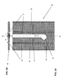
- FIGs. 2A and 2B illustrate a mandrel according to the exemplary embodiment of the invention illustrated in FIG. 1 .
- the mandrel 20 is planar having two faces.
- the mandrel 20 has a positive portion 22 and a negative portion 24 with "p" separating the two portions.
- the mandrel 20 also has a removable portion 26 and a removable incision 28. Also shown are positive feedthrough groove 23 and negative feedthrough groove 25.
- the placement of the grooves can be equidistant from the midline.
- the negative feedthrough groove can be closer to the mid-line, if desired, or the grooves can be placed at any convenient location of the mandrel 20 as needed.
- a battery cover (not shown) can be constructed to fit over the electrodes (not shown) in only one position. This assures that the terminals can be easily identifiable as positive and negative.
- removable portion 26 can be separated from positive portion 22 and negative portion 24 by removable incision 28.
- Removable incision 28 can be deep enough such that mandrel 20 can be broken along the incision 28. This results in individual positive and negative portions 22 and 24 of mandrel 20.
- an orientation notch 29 shown as a foot-type aperture on the midline of mandrel 20. In the embodiment shown, the "foot" points toward negative portion 24 of mandrel 20.
- FIG. 3 shows another embodiment of an interconnect joint for an electrode assembly 16 according to the invention.
- grooves for positive and negative feedthrough pins 42 and 44 are on opposite faces of mandrel 20.
- FIG. 3 also illustrates the conductive connection between mandrel 20, positive and negative feedthrough pins 42 and 44 and positive and negative electrodes 30 and 32.
- Positive and negative electrodes 30 and 32 are interposed between positive and negative feedthrough pins 42 and 44 in grooves on positive and negative portions 22 and 24 of mandrel 20.
- the connection can be secured by welding both feedthrough pins 42 and 44 and electrodes 30 and 32 into the grooves.
- the mandrel when the electrodes can be conductively connected directly to the feedthrough pins, the mandrel does not need to be conductive to establish the conductive interconnect joint. Therefore, in those embodiments of the invention where the mandrel does not need to be electrically conductive to complete the interconnect joint, the mandrel can be made from a non-electrically conductive material. Suitable electrically non-conductive materials,can include polymers including polypropylene, polyethylene, and poly(ethylene-co-tetrafluoroethylene) (ETFE).
- the separator(s) can be heat sealed to the mandrel when the mandrel is prepared from a non-electrically conductive material. For example, an end of the separator can be attached to a portion of the mandrel via heat sealing.
- FIG. 4 is a schematic diagram illustrating mandrel 20 with electrodes 30 and 32 conductively connected to positive and negative portions 22 and 24. Electrodes 30 and 32 can be attached to opposite faces of mandrel 20.
- positive active material 302 can be any of those materials used as such in electrode technology.
- positive active material 302 can be lithium cobalt oxide (rechargeable), carbon monofluoride (CF x ), silver vanadium oxide (primary), or combinations thereof.
- negative active material 320 can be any appropriate negative active material used in electrode technology. Exemplary materials include lithium titanate, artificial graphite powder (MCMB), lithium, or combinations thereof.
- Both positive 30 and negative electrodes 32 can be coated on one side or both sides of the electrode to provide an electron flow suitable to generate a current.
- coating of the electrodes on both sides with active material allows for more efficient use of the two sides of the electrodes, resulting in increased energy and power in contrast to a single side coated electrode.
- the proximal and/or distal ends of the electrodes do not need to be coated on one or both sides. It should be appreciated that any suitable combination of coatings and coated portions of the electrode(s) is within the scope of the invention and is not limiting.
- FIG. 5 illustrates electrodes 30 and 32 connected to mandrel 20, as shown in FIG. 4 .
- Positive and negative feedthrough pins 42 and 44 can be placed in grooves 23 and 25 and secured in place. Feed through pins 42 and 44 and their respective electrodes 30 and 32 can be conductively connected to mandrel 20 by welding. Alternatively, a direct conductive connection between the electrode and the feedthrough pin can be made by attaching either or both positive electrode 30 and negative electrode 32 in grooves 23 and 25 underneath feedthrough pins 42 and 44 respectively.
- feedthrough pins 42 and 44 extend through insulator 70 and battery cover 72 and can be used as battery terminals 80 and 82.
- ferrules 84 which are welded to battery cover 72 to stabilize the terminals and isolate them from battery cover 72.
- a glass seal or sleeve (not shown) can be placed over the feedthrough pin prior to the placement of ferrule 84 to provide a seal between the feedthrough pin and the battery cover and insulating ferrule 84 from the feedthrough pin.
- Suitable materials for ferrule construction can be titanium, titanium alloys or stainless steel.
- Insulator 70 can be made of any insulating material such as, for example, polyethylene, polypropylene, polyethylene terephthalate, polyimide, ethylene/tetrafluoroethylene copolymer (ETFE).
- the insulating material can be a non-conductive film such as, for example, DuPont Kapton® polyimide film.
- the mandrel 20 need not be electrically conductive to complete the interconnect joint. This is because direct connection of the electrodes to the feedthrough pins provides an electrical conduction between the electrodes, the feedthrough pins and battery terminals.
- the battery case will be neutral.
- a stud pin (not shown) can be welded to the battery cover concentric with the position one of the feedthrough pins 42 or 44.
- the case will be at either a negative potential or a positive potential depending at which position the stud pin is secured.
- FIG. 6 illustrates an electrode assembly as shown in FIG. 2 but viewed from the opposite face.
- the electrode assembly has a first separator 50 and a second separator 52 attached to mandrel 20.
- first separator 50 and second separator 52 can be attached so as to be opposed to positive electrode 30 and negative electrode 32 respectively.
- separators 50 and 52 isolate positive and negative electrodes 30 and 32 from each other (shown in FIG. 7A ).
- the separators can be attached to the mandrel 20 using any effective method.
- the separators can be connected by adhesive or tape 54 that adheres the separator to the mandrel.
- Tape material 54 can be a polypropylene, polyethylene, polyester, or nylon resin.
- Adhesives include, for example, polyvinylidenefluoride (PVDF), co-polymers of polyhexafluoropropylene-polyvinylidenefluoride, poly(vinylacetate), polyvinylalcohol, polyethylene oxide, polyvinylpyrolidone, alkylated polyethylene oxide, polyvinyl ether, poly(methylmethacrylate), poly(ethylacrylate), polytetrafluoroethylene, polyvinylchloride, polyacrylonitrile, polyvinylpyridine, styrene-butadiene rubber, silicon and mixtures thereof.
- PVDF polyvinylidenefluoride
- co-polymers of polyhexafluoropropylene-polyvinylidenefluoride poly(vinylacetate), polyvinylalcohol
- polyethylene oxide polyvinylpyrolidone
- alkylated polyethylene oxide polyvinyl ether
- poly(methylmethacrylate)
- FIG. 6 also shows that, as with the single separator 51 used in the embodiments shown in FIGs. 1 and 3 , separators 50 and 52 are wider than electrodes 30 and 32 by a distance 'm'.
- separators 50 and 52 are wider than electrodes 30 and 32 by a distance 'm'.
- FIGs. 7A-7D are schematic, top-plan views of four separate embodiments of coiled jelly roll assemblies providing an interconnect joint according to the invention.
- FIG. 7A shows mandrel 20 having positive and negative feedthrough pins 42 and 44 on the same face with electrodes 30 and 32 connected on opposite faces of the mandrel 20. Uncoated portions of 304 and 322 of electrodes 30 and 32 can be connected to positive 22 and negative 24 portions of mandrel 20. Two separators 50 and 52 can be used to separate electrodes 30 and 32.
- FIG. 7B provides an embodiment of the invention where positive and negative feedthrough pins 42 and 44 are on opposite faces of the mandrel. Uncoated portions of 304 and 322 of positive and negative electrodes 30 and 32 can be conductively connected to feedthrough pins 42 and 44. Uncoated portions 304 and 322 can be positioned behind feedthrough pins 42 and 44 in the feedthrough grooves. Two separators, 50 and 52, are shown in Figure 7B .
- mandrel 20 can be rotated to wind electrodes 30 and 32 and separators 50 and 52 around mandrel 20 to create the jelly roll electrode assembly 16 as shown in FIGs. 7A and 7B.
- FIGs. 7A and 7B also illustrate mandrel 20 integrated into the center of the jelly roll electrode assembly 16 and separators 50 and 52 wound between the positive and negative electrodes 30 and 32 respectively.
- FIGs. 7C and 7D are schematic diagrams of jelly roll assemblies incorporating an interconnect joint using a single separator.
- FIGs. 7C and 7D illustrate separator 51 woven between positive and negative portions 22 and 24 of mandrel 20 to insulate positive 30 and negative 32 electrodes.
- FIG. 7C shows one embodiment of the interconnect joint wherein positive and negative feedthrough pins 42 and 44 can be on the same face of the mandrel 20.
- Uncoated portions 304 and 322 can be conductively connected to opposite faces of the mandrel 20 with separator 51 passing through passage 'p' ( FIG. 3 ) of mandrel 20.
- FIG. 7D shows the interconnect joint where positive and negative feedthrough pins 42 and 44 can be on different faces of the mandrel 20.
- Uncoated portions 304 and 322 can be conductively connected to feedthrough pins 42 and 44 by positioning them in the feedthrough grooves behind feedthrough pins 42 and 44.
- FIGs. 7C and 7D As illustrated in FIGs 7C and 7D , once the components of electrode assembly 16 are assembled, mandrel 20 can be rotated to wind the electrodes 30 and 32 and the single interwoven separator 51 around the mandrel to create the jelly roll electrode assembly 16.
- FIGs. 7C and 7D also illustrate mandrel 20 integrated into the center of the jelly roll electrode assembly 16 with separator 51 wound between the positive and negative electrodes 30 and 32 respectively.
- FIG. 8A shows the electrode assembly in battery case 64 before removable portion 26 is detached.
- battery case 64 is dimensioned so as to approximate the size of the mandrel without removable portion 26.
- FIG. 8B separation of the removable portion results in individual positive portion 22 and negative portion 24 of mandrel 20 integrated into the jelly roll assembly 16 and battery 10.
- Jelly roll assembly 16 fits within battery case 64 as illustrated in FIG 8B . Because positive portion 22 and negative portion 24 are not removed from the electrode assembly 16, telescoping of the jelly roll assembly due to their removal can be minimized or eliminated. Therefore, the jelly roll can be wound or coiled to a tension desired to accommodate the battery rather than coiling the jelly roll to a tension that allows the mandrel to be removed from the coil.
- the instant invention provides a less bulky electrode assembly and, consequently, can be used to provide a smaller battery.
- FIG. 9 illustrates a mandrel 200 according to the invention.
- Mandrel 200 includes a positive portion 220 and a negative portion 240. Both the positive portion 220 and the negative portion 240 include removable portions 260a and 260b, respectively.
- Positive portion 220 further includes a positive feedthrough groove 230 while the negative portion includes a negative feedthrough groove 250.
- a removable incision 280a and 280b delineates the removable portion 260a and 260b from positive portion 220 and negative portion 240 of mandrel 200.
- Orientation notches 290a and 290b can be provided in removable portion 260a and 260b, respectively, of positive portion 220 and negative portion 240 of mandrel 200.
- positive and negative electrodes (not shown) and feedthrough pins (not shown) can be attached to the positive and negative portions 200 and 240 of mandrel 200 as previously described herein. Additionally, it should be understood that feedthrough grooves 230 and 250 can be positioned on opposite sides of mandrel 200.
- Two separators can be attached to positive and negative portions 220 and 240 of mandrel 200 also as previously described.
- a single separator can be passed through passage "p" also as previously described to afford an electrode assembly.
- positive portion 220 and negative portion 240 can be held in place, for example, by a vice and grip winding ligature (not shown) connected to the removable portions 260a and 260b.
- a vice and grip winding ligature (not shown) connected to the removable portions 260a and 260b.
- the removable portions can be detached.
- FIG. 8 allows each positive portion 220 and negative portion 240 to be fabricated from different materials as needed, thereby optimizing the battery and battery chemistry for a desired use.
- FIGs. 10A and 10B illustrate another mandrel 300 according to the invention.
- FIG. 10A is a side-plan view showing a mandrel 300 with grooves 340 and 342 designed and configured for securing a stud pin (not shown) to the mandrel 300.
- Mandrel 300 also includes grooves 323 and 325 designed and configured to accept positive and negative feedthrough pins (not shown).
- Electrodes 30 and 32 can be secured to mandrel 300 by stud pins (as shown in FIG. 12 ). For example, electrodes 30 and 32 can be placed into grooves 340 and 342. A stud pin can then be placed over the electrode and secured into the groove to effect attachment between positive portion 322 and negative portion 324 of mandrel 300.
- Stud pins can be made of any conductive or non-conductive material. As illustrated in FIGs. 10A and 10B , stud pin grooves 340 and 342 can be located on opposite faces of the mandrel. As with mandrel 20, illustrated in FIG. 2 , mandrel 300 includes a positive portion 322, a negative portion 324 and a removable portion 326. Positive and negative portions 322 and 324 are adjacent to removable incision 328. Mandrel 300 also has positive and negative feedthrough grooves 323 and 325 dimensioned and configured to accept positive and negative feedthrough pins (not shown). In this embodiment, the grooves 323 and 325 are on opposite faces of the mandrel.
- Positive and negative electrodes (not shown) and feedthrough pins (not shown) can be attached to the positive and negative portions 322 and 324 of mandrel 300 as previously described herein.
- Two separators (also not shown) can be attached to positive and negative portions 322 and 324 of mandrel 300 also as previously described.
- a single separator can be passed through passage "p" also as previously described to afford an electrode assembly.
- FIGs. 11A and 11B illustrate another mandrel according to the invention.
- Mandrel 400 includes a positive portion 422, a negative portion 424 and a removable portion 426. Positive and negative portions 422 and 424 are adjacent to removable incision 428.
- mandrel 400 is designed and configured for the electrodes (not shown) to be attached to mandrel 400 using a stud pin (444 shown in FIG. 12 ). As shown in FIG.
- mandrel 400 provides for positive stud pin groove 440 and positive feedthrough pin groove 423 to be on the same face of mandrel 400 while negative stud pin groove 442 and negative feed through pin groove 425 are on the opposite face of the mandrel.
- positive and negative electrodes (not shown) and feedthrough pins (not shown) can be attached to positive and negative portions 422 and 424 of mandrel 400 as previously described herein.
- Two separators (also not shown) can be attached to positive and negative portions 422 and 424 of mandrel 400 also as previously described.
- a single separator can be passed through passage "p" also as previously described to afford an electrode assembly.
- FIG. 12 is a side-plan view of mandrel 400 ( FIGs. 10A and 10B ) partially assembled into an electrode assembly.
- FIG. 12 shows positive electrode 30 anchored underneath stud pin 444 in groove 440. Both electrode 30 and stud pin 444 can be connected to mandrel 400 together in groove 440 to provide conductive attachment of electrode 30 to mandrel 400 and to feedthrough pin 42 to create a conductive interconnect joint.
- Positive feedthrough pin 42 and negative feedthrough pin 44 are on the same face of the mandrel while negative electrode 32 can be connected to mandrel 400 using a stud pin (not shown) on the opposite face of the mandrel 400.
- the mandrel can be made from a non-electrically conductive material.
- electrically non-conductive materials can include polymers including polypropylene, polyethylene, and poly(ethylene-co-tetrafluoroethylene) (ETFE).
- ETFE poly(ethylene-co-tetrafluoroethylene)
- the mandrel can resemble mandrel 20 as illustrated in FIGs. 2A and 2B such that there is a direct electrical connection between the electrodes and the feedthrough pins positioned in the mandrel.
Landscapes
- Engineering & Computer Science (AREA)
- Manufacturing & Machinery (AREA)
- Chemical & Material Sciences (AREA)
- Chemical Kinetics & Catalysis (AREA)
- Electrochemistry (AREA)
- General Chemical & Material Sciences (AREA)
- Secondary Cells (AREA)
- Connection Of Batteries Or Terminals (AREA)
- Battery Electrode And Active Subsutance (AREA)
- Cell Electrode Carriers And Collectors (AREA)
Description
- The invention relates to a battery and to a method of manufacture using a mandrel that allows for increased compactness.
- Batteries for medical devices have demanding requirements. They should be small, have a long life, high power output, low self-discharge rate, compact size and high reliability. The need for miniaturization while maintaining or increasing output means that as much of the battery footprint as possible should be used for power storage resulting in the concomitant elimination of dead space. However, while the elimination of dead space should result in greater miniaturization, it also results in a greater difficulty of assembly due to the increasingly small size of the component parts.
- Traditionally, jelly roll type batteries have been made by using a mandrel to wrap electrodes around. Once wrapped, the mandrel is removed providing a jelly roll wrapped electrode assembly for use in a battery. However, removal of the mandrel from the core of the jelly roll inherently presents the potential of damaging the jelly roll due to the possibility of pulling the core of the jelly roll out with the mandrel. Therefore, the jelly roll should not be wrapped tight to avoid this problem. Conversely, a loosely wrapped jelly roll wastes space and decreases battery capacity and power due to size constraints. More recently, jelly roll storage batteries have been made using a rod-shaped, non-conductive, non-deformable core around which electrodes are wrapped. Conductive tabs are added to each electrode to complete the circuit.
-
U.S. patent 7,442,465 to Kim et al. , discloses a rechargeable battery which has a non-deformation core. Once the positive and negative electrodes are wound around the core, conductive tabs are attached to the electrodes and the core serves to prevent deformation of the jelly roll, but does not conduct current. -
U.S. provisional patent application 60/348,665 to Nakahara et al. describes a feedthrough pin that is directly connected to an inner end of an electrode. The pin extends from the jelly roll and through the battery case and functions as a battery terminal. The feedthrough pin fits into a slotted 'C'-shaped mandrel. The positive electrode is conductively connected to the pin which fits within the 'C'-shaped mandrel. As the positive electrode is wound, a separator is inserted between the feedthrough pin/mandrel and the positive electrode. A negative electrode is inserted between the separator and the pin/mandrel. The separator and negative electrode are held in the jelly roll by the tension created between the feedthrough pin/mandrel and the positive electrode. After winding, a metal tab is welded to the negative electrode and the tab contacts the battery case endcap to complete the circuit. - Both of the aforementioned batteries require the placement of at least one tab on an electrode to complete the circuit during or after winding the electrodes. In either case, the passive connection of one of the electrodes to the case is required for the circuit to be completed.
- Therefore, a need exists for an improved electrode assembly.
- The present invention provides a mandrel useful in making a jelly roll electrode assembly and an electric storage battery. The mandrel includes a positive portion, a negative portion and one or more removable portions adjacent to the positive and/or negative portions. A passage is provided between the positive and negative portions. The mandrel can be planar having two faces with a groove on each of the positive and negative portions. The grooves can be on the same or opposite faces of the mandrel. The grooves are dimensioned to accommodate positive and negative feedthrough pins.
- The positive and negative electrodes and the positive and negative feedthrough pins can be conductively connected to the mandrel to provide an electrode assembly. One or more separators can be used to insulate the electrodes. The removable portion can be used as a handle when the mandrel is rotated to wrap the electrode and the one or more separators around the mandrel to make a jelly roll electrode assembly. The jelly roll assembly can be secured by heat sealing one or more protruding ends of the one or more separators to each other or to an underlying separator layer.
- In one aspect, when an electrode assembly is made using the mandrel, a single separator can be passed through a passage between the positive and the negative portion of the mandrel. In this embodiment the invention includes an electrode assembly comprising: (a) a planar mandrel having a first face and a second face with the mandrel including a positive portion, a negative portion; (b) a positive electrode; (c) a negative electrode; (d) a positive feedthrough pin; (e) a negative feedthrough pin; and (f) a single separator. The mandrel includes a passage from the first face to the second face dividing the positive portion and the negative portion. The separator passes through the passage in the mandrel so as to be juxtaposed to the positive portion on the first face of the mandrel and the negative portion on the second face of the mandrel. The positive electrode, the separator and the negative electrode can be wound around the mandrel to provide a jelly roll electrode assembly. The mandrel further includes one or more removable portions adjacent to the positive and/or negative portions of the mandrel. The removable portions can be removed after assembly.
- In another aspect, the invention provides for making a conductive connection between the electrodes and the feedthrough pins using the mandrel as a platform. In this embodiment, the positive and negative electrodes can be electrically connected on the mandrel. When the mandrel is made of an electrically conductive material, the positive and negative feedthrough pins and the positive and negative electrodes do not have to be in direct contact with each other to be electrically connected on the mandrel. When the mandrel is made of a non-electrically conductive material, the positive and negative electrodes can be directly opposed to each other on the mandrel. By providing a conductive connection between the electrodes and the feedthrough pins on the mandrel, exposed ends of the feedthrough pins provide terminals for the battery. This construction provides for a battery case that is neutral too.
- In still another aspect, the invention provides a method of sealing a coiled jelly roll electrode assembly by utilizing protruding ends of one or more separators used in the electrode assembly. In this embodiment, the terminus of one or more separators extends beyond the length of one or more electrodes of the wrapped jelly roll assembly providing a protruding end(s) of the separator. The protruding end(s) of the separator extends beyond the electrodes sufficient to be sealed to each other or to an underlying layer of separator. Generally, excess separator material can be wrapped 1 to 5 times around the jelly roll. In one aspect, the wrapped jelly roll assembly can be contacted with a heating block on one or more sides of the jelly roll. The separator material separator can be heat sealed to an underlying layer of separator, thus securing the jelly roll assembly in a coiled position.
- The invention further includes a method of making an electric storage battery including placing the electrode assembly in a case.
- These and other features and advantages of the present invention will be set forth or will become more fully apparent in the description that follows and in the appended claims. The features and advantages may be realized and obtained by means of the instruments and combinations particularly pointed out in the appended claims. Furthermore, the features and advantages of the invention may be learned by the practice of the invention or will be apparent from the description, as set forth hereinafter.
- Various exemplary embodiments of the compositions and methods according to the invention will be described in detail, with reference to the following figures wherein:
-
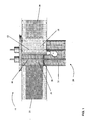
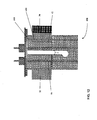
FIG. 1 is a schematic diagram of one embodiment of an electrode assembly made using a mandrel according to the invention. In this embodiment, the feedthrough pins are on the same side face of the mandrel; -
FIGs. 2A and 2B illustrate a mandrel according to the embodiment of the invention illustrated inFIG. 1 .FIG. 2A is a side-plan view of the mandrel.FIG. 2B is a top-plan view of the mandrel ofFIG. 2A ; -
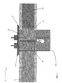
FIG. 3 is a schematic diagram of an electrode assembly made using another embodiment of the mandrel according to the invention. In this embodiment, the feed through pins are on opposite faces of the mandrel; -
FIG. 4 is a schematic diagram of the mandrel illustrated inFIG. 1 with electrodes attached to the positive portion and the negative portion of the mandrel; -
FIG. 5 is a schematic diagram of the mandrel shown inFIG. 4 with positive and negative feedthrough pins attached and a battery cap and insulator; -
FIG. 6 illustrates the embodiment of a completed electrode assembly using the mandrel shown inFIG. 4 and with two separators attached. The view shown inFIG. 6 is from the opposite face as the view fromFIG. 5 ; -
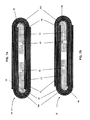
FIGs. 7A, 7B ,7C and 7D are schematic, top-plan views of four jelly roll electrode assemblies using different mandrels to make an interconnect joint according to the invention; -
FIGs. 8A and 8B show a battery made using the coiled electrode assembly made using a mandrel according to the invention.FIG. 8A shows the electrode assembly in the battery case before the removable portion is detached.FIG. 7B shows the completed battery with the removable portion detached and the electrode assembly ready to be sealed in the battery case; -
FIG. 9 is a schematic diagram of another embodiment of the mandrel according to the invention having two separate positive and negative portions, each with its own removable portion; -
FIGs. 10A and 10B illustrate a separate embodiment of a mandrel useful in making an interconnect according to the invention. This embodiment of the interconnect joint uses a mandrel having a separate stud pin for conductively connecting the positive and negative electrodes.FIG. 10A is a side-plan view showing a mandrel with the location for a groove including a welding site for a stud pin used to complete the connection between the mandrel and the positive and negative electrode pins.FIG. 10B is a top-plan view of the mandrel shown inFIG. 10A ; -
FIGs. 11A and 11B illustrate another embodiment of a mandrel useful in making an interconnect according to the invention.FIG. 11A is a side-plan view of the mandrel according to the invention andFIG. 11B is a top-plan view of the same mandrel. This embodiment of the interconnect joint uses a mandrel having separate grooves for stud pins for conductively connecting the positive and negative electrodes; -
FIG. 12 is a side-plan view of a partially assembled electrode assembly according to one embodiment of the invention using the mandrel shown inFIGs. 10A and 10B . - It must be noted that as used herein and in the appended claims, the singular forms "a", "an" and "the" include plural reference unless the context clearly dictates otherwise. As well, the terms "a" (or "an"), "one or more" and "at least one" can be used interchangeably herein. It is also to be noted that the terms "comprising", "including", "characterized by" and "having" can be used interchangeably.
- Unless defined otherwise, all technical and scientific terms used herein have the same meanings as commonly understood by one of ordinary skill in the art to which this invention belongs.
- As used herein, the term "mandrel" means an interior core at least a portion of which can be an integral part of the electrode assembly. The term "interconnect joint" refers to a conductive connection between the electrical components of a battery including a mandrel. While the mandrel may, itself not be conductive, those parts of the electrode assembly required for an electric current, including, at least, positive and negative electrodes and positive and negative feedthrough pins are conductively connected on the mandrel. In addition, the term "electrode" is used to refer to an electrode substrate that can be coated with an active material. The electrode can include a current collecting substrate in the form of multiple "plates" or panels conductively connected to each other. Alternatively, the electrode comprises a substrate in the form of a strip of thin conductive material such as a foil. When the electrode is formed using a foil or thin conductive strip as a substrate, the electrode can be considered an "electrode strip".
- As used herein the terms "heat sealed" and "heat sealer" refer to conventional methods known in the art in which a machine applies heat to seal a material such as a thermoplastic material. Of the several types of heat sealers, one is a continuous heat sealer that applies a continuous heat. A continuous heat device or sealer can be constructed using a cartridge heater that is inserted into an appropriate size opening in a block, such as metal or ceramic, having a predetermined shape and desirable thermal properties. A second type of heat sealer is an impulse heat sealer. Generally, an impulse heat sealer uses a stationary element (such as a nichrome wire) that is heated by passing a current through it for a period of time.
- The invention and the various features and advantageous details thereof are explained more fully with reference to the non-limiting embodiments that are illustrated in the accompanying drawings and detailed in the following description. Descriptions of well known components and processing techniques are omitted so as not to unnecessarily obscure the invention in detail but such descriptions are, nonetheless, included in the disclosure by incorporation by reference of the citations discussed. It should be understood, however, that the detailed description and the specific examples, while indicating preferred embodiments of the invention, are given by way of illustration only and not by way of limitation. Various substitutions, modifications, additions and/or rearrangements within the scope of the underlying inventive concept will become apparent to those skilled in the art from this detailed description.
- The present invention provides a mandrel useful in making a jelly roll electrode assembly and an electric storage battery. The mandrel includes a positive portion, a negative portion and one or more removable portions adjacent to the positive and/or negative portion(s). A passage is provided between the positive and negative portions. The mandrel can be planar having two faces with a groove on each of the positive and negative portions. The grooves can be on the same or opposite faces of the mandrel. The grooves are dimensioned to accommodate positive and negative feedthrough pins.
- The positive and negative electrodes and the positive and negative feedthrough pins can be conductively connected to the mandrel when used to make an electrode assembly. One or more separators can be used to insulate the electrodes. For example, a separator can be passed through the passage of the mandrel so as to be juxtaposed alongside both the positive and negative electrodes. The removable portion(s) can be used as a handle to rotate mandrel, electrodes and one or more separators. Rotation of the mandrel wraps the electrodes and one or more separators around the mandrel to provide a jelly roll electrode assembly. The jelly roll assembly can be secured by heat sealing one or more protruding ends of the one or more separators with heat.
- Referring now to
FIG. 1 , one embodiment of an electrode assembly according to the invention is illustrated.FIG. 1 illustrates anelectrode assembly 16 including aconductive mandrel 20 having a positive portion (obscured by separator 51) and anegative portion 24, positive andnegative electrodes Mandrel 20 further includesremovable portion 26 and aremovable incision 28. As illustrated,positive electrode 30 andnegative electrode 32 can be conductively connected to theconductive mandrel 20 on opposite faces while feedthrough pins 42 and 44 can be conductively connected in place on the same face of the mandrel thereby creating the interconnect joint. In the embodiment shown,positive electrode 30 and thenegative electrode 32 can be conductively connected by weldingelectrodes mandrel 20. In this embodiment, asingle separator 51 can be interwoven between positive andnegative portions mandrel 20 through passage "p" to provideelectrode assembly 16. - It should be appreciated that the mandrel can be formed of any conductive material. For example, the mandrel can be formed of stainless steel or aluminum. Alternatively, the mandrel can be made from pure titanium or titanium alloy such as grade 5 or
grade 23, nickel, copper and combinations thereof. - While the mandrel can be made using any appropriate process, in one aspect the mandrel can be made using electric discharge machining (EDM). Alternatively, the mandrel can be made by metal extrusion or by injection molding depending on the needs of the battery and the composition of the mandrel. The grooves for the feedthrough pins can be made in the mandrel by machining, etching, or other suitable methods to provide a groove.
- The width of
mandrel 20 can be from about 0.2 to about 0.5 inches (5.08 -12.7 mm), more particularly from about 0.25 to about 0.4 inches (6.35 - 10-16 mm) and most particularly from about 0.3 to about 0.35 inches (7.62 - 8.89 mm). Generally, the length of the mandrel ranges from about 0.5 inches to about 1 inch (12.7 - 25.4 mm), more particularly from about 0.6 to about 0.8 inches (15.24 - 20.32 mm) and most particularly from about 0.7 to about 0.75 inches (17.78 - 19.05 mm). The thickness of the mandrel ranges from about 0.01 to about 0.05 inches (0.254 - 1.27 mm), more particularly from about 0.015 inches to about 0.03 inches (0.381 - 0.762 mm) and most particularly from about 0.02 to about 0.025 inches (0.508 - 0.635 mm). - Those of skill in the art will appreciate
grooves -
Electrodes - The electrodes can vary in composition depending on the battery chemistry being used and the mandrel can be optimized for such.
- Suitable separator material can be any non-conductive material such as polyethylene, polypropylene and layered combinations thereof. The separator generally has a larger width and length than the electrode(s) it covers so as to fully encase the electrode(s). Suitable separators have a length of from about 4 inches to about 36 inches (10.16 - 91.44 cm), in particular from about 8 inches to about 34 inches (20.32 - 86.36 cm) and most particularly from about 12 inches to about 30 inches (30.48 - 76.2 cm)and widths of from about 0.2 inches to about 2 inches (5.08 - 50.8 mm), in particular from about 0.3 inches to about 1.75 inches (7.62 - 44.45 mm) and most particularly from about 0.4 inches to about 1.5 inches (10.16 - 38.1 mm). Suitable thicknesses for separators range from about 0.0008 inches to about 0.004 inches (0.02032 - 0.1016 mm). Generally,
separator 51 can be sized appropriately to extend beyond the bottom portion of positive andnegative portions removable portion 26. - Feedthrough pins can be sized to fit within the grooves and can be made of any electrically conductive material. For example, feedthrough pins 42 and 44 can be made of steel, platinum, aluminum and titanium, etc. In some embodiments, the feedthrough pins can be made of an alloy such as, for example, platinum-iridium such as 90Pt/10Ir. The length of the positive and negative feedthrough pins can range from about 0.4 to about 1 inches (10.16 - 25.4 mm) in length, more particularly from about 0.5 to about 0.75 inches (12.7 - 19.05 mm) and most particularly from about 0.5 to about 0.7 inches (12.7 -17.78 mm). The diameter of the feedthrough pins can vary and can be from about 0.050 to about 0.3 inches (1.27 - 7.62 mm), in particular from about 0.01 to about 0.025 inches (0.254 - 0.635 mm) and most particularly from about 0.01 to about 0.015 inches (0.254 - 0.381 mm). The feedthrough pins extend outside of the battery case and can be cut to length as required.
- The phrase "removable portion" refers to a portion of the mandrel that can be detached from the remainder of the mandrel. This can be accomplished by scoring a groove deep enough to allow the portion to be "snapped off" from the remainder of the mandrel. Alternatively, the removal portion can be detached by cutting, breaking, tearing or clipping the portion from the remainder of the mandrel.
-
FIGs. 2A and 2B illustrate a mandrel according to the exemplary embodiment of the invention illustrated inFIG. 1 . Themandrel 20 is planar having two faces. Themandrel 20 has apositive portion 22 and anegative portion 24 with "p" separating the two portions. In addition, themandrel 20 also has aremovable portion 26 and aremovable incision 28. Also shown arepositive feedthrough groove 23 andnegative feedthrough groove 25. -
FIG. 2B is a top-plan view ofmandrel 20 showing the mid-line ofmandrel 20, along line 'm-m'. As illustrated inFIG. 2B ,feedthrough grooves feedthrough pins 42 and 44 (FIG. 1 ). In the embodiment illustrated inFIGs. 2A and 2B ,positive feedthrough groove 23 is placed closer to midline 'm-m' ofmandrel 20 thannegative feedthrough groove 25. This is illustrated by the distance 'd' frompositive electrode groove 23 to the midline compared to the distance 'd1' from thenegative electrode groove 25 to the midline 'm-m'. Of course, those of skill in the art will appreciate that the placement of the grooves can be equidistant from the midline. Alternatively, the negative feedthrough groove can be closer to the mid-line, if desired, or the grooves can be placed at any convenient location of themandrel 20 as needed. However, those of skill in the art will appreciate that by having the feedthrough pins positioned at two different distances from the midline, a battery cover (not shown) can be constructed to fit over the electrodes (not shown) in only one position. This assures that the terminals can be easily identifiable as positive and negative. - Further, as shown in
FIG. 2A ,removable portion 26 can be separated frompositive portion 22 andnegative portion 24 byremovable incision 28.Removable incision 28 can be deep enough such thatmandrel 20 can be broken along theincision 28. This results in individual positive andnegative portions mandrel 20. Also illustrated inFIG. 2A is anorientation notch 29 shown as a foot-type aperture on the midline ofmandrel 20. In the embodiment shown, the "foot" points towardnegative portion 24 ofmandrel 20. Those of skill in the art will realize that such orientation guides are not necessary formandrel 20 to function nor do they have to point towards the negative portion of the mandrel. However, such guides are helpful if consistently used. -
FIG. 3 shows another embodiment of an interconnect joint for anelectrode assembly 16 according to the invention. In this embodiment, grooves for positive and negative feedthrough pins 42 and 44 are on opposite faces ofmandrel 20.FIG. 3 also illustrates the conductive connection betweenmandrel 20, positive and negative feedthrough pins 42 and 44 and positive andnegative electrodes negative electrodes negative portions mandrel 20. In some embodiments, the connection can be secured by welding both feedthrough pins 42 and 44 andelectrodes - Those of skill in the art will appreciate that when the electrodes can be conductively connected directly to the feedthrough pins, the mandrel does not need to be conductive to establish the conductive interconnect joint. Therefore, in those embodiments of the invention where the mandrel does not need to be electrically conductive to complete the interconnect joint, the mandrel can be made from a non-electrically conductive material. Suitable electrically non-conductive materials,can include polymers including polypropylene, polyethylene, and poly(ethylene-co-tetrafluoroethylene) (ETFE). Advantageously, the separator(s) can be heat sealed to the mandrel when the mandrel is prepared from a non-electrically conductive material. For example, an end of the separator can be attached to a portion of the mandrel via heat sealing.
-
FIG. 4 is a schematicdiagram illustrating mandrel 20 withelectrodes negative portions Electrodes mandrel 20. -
Positive electrode 30 can be coated with a positiveactive material 302. As illustrated,positive electrode 30 has aproximal end 304 that is not coated with active material.Proximal end 304 can be attached at 306 topositive portion 22 ofmandrel 20. Similarly,negative electrode 32 can be coated with a negativeactive material 320.Proximal end 322 of negative electrode 21 is not coated with active material and facilitates attachment (not shown) to thenegative portion 24 ofmandrel 20.Electrodes - Those of skill in the art will appreciate that positive
active material 302 can be any of those materials used as such in electrode technology. For example, positiveactive material 302 can be lithium cobalt oxide (rechargeable), carbon monofluoride (CFx), silver vanadium oxide (primary), or combinations thereof. Similarly, negativeactive material 320 can be any appropriate negative active material used in electrode technology. Exemplary materials include lithium titanate, artificial graphite powder (MCMB), lithium, or combinations thereof. - Both positive 30 and
negative electrodes 32 can be coated on one side or both sides of the electrode to provide an electron flow suitable to generate a current. However, those of skill in the art will appreciate that coating of the electrodes on both sides with active material allows for more efficient use of the two sides of the electrodes, resulting in increased energy and power in contrast to a single side coated electrode. It should be understood that the proximal and/or distal ends of the electrodes do not need to be coated on one or both sides. It should be appreciated that any suitable combination of coatings and coated portions of the electrode(s) is within the scope of the invention and is not limiting. -
FIG. 5 illustrateselectrodes mandrel 20, as shown inFIG. 4 . Positive and negative feedthrough pins 42 and 44 can be placed ingrooves pins respective electrodes positive electrode 30 andnegative electrode 32 ingrooves FIG. 5 , feedthrough pins 42 and 44 extend throughinsulator 70 andbattery cover 72 and can be used asbattery terminals ferrules 84 which are welded tobattery cover 72 to stabilize the terminals and isolate them frombattery cover 72. A glass seal or sleeve (not shown) can be placed over the feedthrough pin prior to the placement offerrule 84 to provide a seal between the feedthrough pin and the battery cover and insulatingferrule 84 from the feedthrough pin. - Suitable materials for ferrule construction can be titanium, titanium alloys or stainless steel.
-
Insulator 70 can be made of any insulating material such as, for example, polyethylene, polypropylene, polyethylene terephthalate, polyimide, ethylene/tetrafluoroethylene copolymer (ETFE). In one aspect, the insulating material can be a non-conductive film such as, for example, DuPont Kapton® polyimide film. - In those embodiments where feedthrough pins 42 and 44 and
electrodes feedthrough grooves mandrel 20 need not be electrically conductive to complete the interconnect joint. This is because direct connection of the electrodes to the feedthrough pins provides an electrical conduction between the electrodes, the feedthrough pins and battery terminals. - Those of skill in the art can appreciate that under the above described conditions the battery case will be neutral. However, in other embodiments, a stud pin (not shown) can be welded to the battery cover concentric with the position one of the feedthrough pins 42 or 44. Thus, in this embodiment, the case will be at either a negative potential or a positive potential depending at which position the stud pin is secured.
-
FIG. 6 illustrates an electrode assembly as shown inFIG. 2 but viewed from the opposite face. In this embodiment, the electrode assembly has afirst separator 50 and asecond separator 52 attached tomandrel 20. As shown,first separator 50 andsecond separator 52 can be attached so as to be opposed topositive electrode 30 andnegative electrode 32 respectively. When wound,separators negative electrodes FIG. 7A ). The separators can be attached to themandrel 20 using any effective method. For example, the separators can be connected by adhesive ortape 54 that adheres the separator to the mandrel.Tape material 54 can be a polypropylene, polyethylene, polyester, or nylon resin. Adhesives include, for example, polyvinylidenefluoride (PVDF), co-polymers of polyhexafluoropropylene-polyvinylidenefluoride, poly(vinylacetate), polyvinylalcohol, polyethylene oxide, polyvinylpyrolidone, alkylated polyethylene oxide, polyvinyl ether, poly(methylmethacrylate), poly(ethylacrylate), polytetrafluoroethylene, polyvinylchloride, polyacrylonitrile, polyvinylpyridine, styrene-butadiene rubber, silicon and mixtures thereof. -
FIG. 6 also shows that, as with thesingle separator 51 used in the embodiments shown inFIGs. 1 and3 ,separators electrodes electrodes separators electrodes -
FIGs. 7A-7D are schematic, top-plan views of four separate embodiments of coiled jelly roll assemblies providing an interconnect joint according to the invention.FIG. 7A showsmandrel 20 having positive and negative feedthrough pins 42 and 44 on the same face withelectrodes mandrel 20. Uncoated portions of 304 and 322 ofelectrodes mandrel 20. Twoseparators separate electrodes -
FIG. 7B provides an embodiment of the invention where positive and negative feedthrough pins 42 and 44 are on opposite faces of the mandrel. Uncoated portions of 304 and 322 of positive andnegative electrodes pins Uncoated portions Figure 7B . - Once the components of the
electrode assembly 16 are assembled,mandrel 20 can be rotated towind electrodes separators mandrel 20 to create the jellyroll electrode assembly 16 as shown inFIGs. 7A and 7B. FIGs. 7A and 7B also illustratemandrel 20 integrated into the center of the jellyroll electrode assembly 16 andseparators negative electrodes -
FIGs. 7C and 7D are schematic diagrams of jelly roll assemblies incorporating an interconnect joint using a single separator.FIGs. 7C and 7D illustrateseparator 51 woven between positive andnegative portions mandrel 20 to insulate positive 30 and negative 32 electrodes.FIG. 7C shows one embodiment of the interconnect joint wherein positive and negative feedthrough pins 42 and 44 can be on the same face of themandrel 20.Uncoated portions mandrel 20 withseparator 51 passing through passage 'p' (FIG. 3 ) ofmandrel 20.FIG. 7D shows the interconnect joint where positive and negative feedthrough pins 42 and 44 can be on different faces of themandrel 20.Uncoated portions pins - As illustrated in
FIGs 7C and 7D , once the components ofelectrode assembly 16 are assembled,mandrel 20 can be rotated to wind theelectrodes separator 51 around the mandrel to create the jellyroll electrode assembly 16.FIGs. 7C and 7D also illustratemandrel 20 integrated into the center of the jellyroll electrode assembly 16 withseparator 51 wound between the positive andnegative electrodes - Those of skill in the art will appreciate that, by positioning a
single separator 51 through passage "p", the tension of the jelly roll maintains theseparator 51 in place. The jelly roll can be wound with a desired tension without risk of the separator becoming dislodged from its position. In addition, those of skill in the art will further appreciate that, by use of the interconnect joint, whether a single separator is used or two different separators are used, there is no need for the placement of extraneous tabs to act as electrode terminals. The interconnect joint results in the ends of the feedthrough pins 42 and 44 being usable as positive andnegative battery terminals - Rotating the mandrel to coil the jelly roll assembly can be accomplished by using the
removable portion 26. Rotating the mandrel to wind or coil the jelly roll assembly can be performed manually. Alternatively, the process can be automated. For example, theremovable portion 26 ofmandrel 20 can be attached to a ligature or other holding mechanism (not shown) which can be turned by a motor. Themandrel 20 can be rotated and the process of coiling thejelly roll assembly 16 can be automated. Once wound, those of skill in the art will appreciate that any suitable means can be used to keep the electrodes in place once rolled. For example, simple insulating tape can be used such as, for example, Teflon, or polyimide tape such as, for example, DuPont Kapton®. -
FIG. 8A shows the electrode assembly inbattery case 64 beforeremovable portion 26 is detached. As illustrated,battery case 64 is dimensioned so as to approximate the size of the mandrel withoutremovable portion 26. As shown inFIG. 8B , separation of the removable portion results in individualpositive portion 22 andnegative portion 24 ofmandrel 20 integrated into thejelly roll assembly 16 andbattery 10.Jelly roll assembly 16 fits withinbattery case 64 as illustrated inFIG 8B . Becausepositive portion 22 andnegative portion 24 are not removed from theelectrode assembly 16, telescoping of the jelly roll assembly due to their removal can be minimized or eliminated. Therefore, the jelly roll can be wound or coiled to a tension desired to accommodate the battery rather than coiling the jelly roll to a tension that allows the mandrel to be removed from the coil. Thus, the instant invention provides a less bulky electrode assembly and, consequently, can be used to provide a smaller battery. -
FIG. 9 illustrates amandrel 200 according to the invention.Mandrel 200 includes apositive portion 220 and anegative portion 240. Both thepositive portion 220 and thenegative portion 240 includeremovable portions Positive portion 220 further includes apositive feedthrough groove 230 while the negative portion includes anegative feedthrough groove 250. As illustrated inFIG. 8 , aremovable incision removable portion positive portion 220 andnegative portion 240 ofmandrel 200.Orientation notches removable portion positive portion 220 andnegative portion 240 ofmandrel 200. - It should be understood that positive and negative electrodes (not shown) and feedthrough pins (not shown) can be attached to the positive and
negative portions mandrel 200 as previously described herein. Additionally, it should be understood thatfeedthrough grooves mandrel 200. - Two separators (not shown) can be attached to positive and
negative portions mandrel 200 also as previously described. Alternatively, a single separator can be passed through passage "p" also as previously described to afford an electrode assembly. - During assembly,
positive portion 220 andnegative portion 240 can be held in place, for example, by a vice and grip winding ligature (not shown) connected to theremovable portions FIG. 7B , once the jelly roll is coiled, the removable portions can be detached. Those of skill in the art will appreciate that the mandrel shown inFIG. 8 allows eachpositive portion 220 andnegative portion 240 to be fabricated from different materials as needed, thereby optimizing the battery and battery chemistry for a desired use. -
FIGs. 10A and 10B illustrate anothermandrel 300 according to the invention.FIG. 10A is a side-plan view showing amandrel 300 withgrooves mandrel 300.Mandrel 300 also includesgrooves Electrodes 30 and 32 (not shown) can be secured tomandrel 300 by stud pins (as shown inFIG. 12 ). For example,electrodes grooves positive portion 322 andnegative portion 324 ofmandrel 300. Stud pins can be made of any conductive or non-conductive material. As illustrated inFIGs. 10A and 10B ,stud pin grooves mandrel 20, illustrated inFIG. 2 ,mandrel 300 includes apositive portion 322, anegative portion 324 and aremovable portion 326. Positive andnegative portions removable incision 328.Mandrel 300 also has positive andnegative feedthrough grooves grooves - Positive and negative electrodes (not shown) and feedthrough pins (not shown) can be attached to the positive and
negative portions mandrel 300 as previously described herein. Two separators (also not shown) can be attached to positive andnegative portions mandrel 300 also as previously described. Alternatively, a single separator can be passed through passage "p" also as previously described to afford an electrode assembly. -
FIGs. 11A and 11B illustrate another mandrel according to the invention.Mandrel 400 includes apositive portion 422, anegative portion 424 and aremovable portion 426. Positive andnegative portions removable incision 428. As withmandrel 300, illustrated inFIGs. 10A and 10B ,mandrel 400 is designed and configured for the electrodes (not shown) to be attached tomandrel 400 using a stud pin (444 shown inFIG. 12 ). As shown inFIG. 11A ,mandrel 400 provides for positivestud pin groove 440 and positivefeedthrough pin groove 423 to be on the same face ofmandrel 400 while negativestud pin groove 442 and negative feed throughpin groove 425 are on the opposite face of the mandrel. - As with
FIGs. 9 ,10A and 10B , positive and negative electrodes (not shown) and feedthrough pins (not shown) can be attached to positive andnegative portions mandrel 400 as previously described herein. Two separators (also not shown) can be attached to positive andnegative portions mandrel 400 also as previously described. Alternatively, a single separator can be passed through passage "p" also as previously described to afford an electrode assembly. -
FIG. 12 is a side-plan view of mandrel 400 (FIGs. 10A and 10B ) partially assembled into an electrode assembly.FIG. 12 showspositive electrode 30 anchored underneathstud pin 444 ingroove 440. Bothelectrode 30 andstud pin 444 can be connected tomandrel 400 together ingroove 440 to provide conductive attachment ofelectrode 30 tomandrel 400 and to feedthroughpin 42 to create a conductive interconnect joint.Positive feedthrough pin 42 andnegative feedthrough pin 44 are on the same face of the mandrel whilenegative electrode 32 can be connected tomandrel 400 using a stud pin (not shown) on the opposite face of themandrel 400. - Two separators (also not shown) can be attached to positive and
negative portions mandrel 400 also as previously described. Alternatively, a single separator can be passed through passage "p" also as previously described to afford an electrode assembly. - In an alternative embodiment, the mandrel can be made from a non-electrically conductive material. Such electrically non-conductive materials can include polymers including polypropylene, polyethylene, and poly(ethylene-co-tetrafluoroethylene) (ETFE). The mandrel can resemble
mandrel 20 as illustrated inFIGs. 2A and 2B such that there is a direct electrical connection between the electrodes and the feedthrough pins positioned in the mandrel. - While this invention has been described in conjunction with the various exemplary embodiments outlined above, various alternatives, modifications, variations, improvements and/or substantial equivalents, whether known or that are or may be presently unforeseen, may become apparent to those having at least ordinary skill in the art. Accordingly, the exemplary embodiments according to this invention, as set forth above, are intended to be illustrative not limiting. Various changes may be made without departing from the scope of the invention which is defined by the claims.
Claims (15)
- An electrode assembly comprising:a mandrel (20) comprising a positive portion (22), a negative portion (24), and a removable portion (26);wherein the positive portion and negative portion are adjacent to and connected to the removable portion; andwherein the mandrel includes a passage from the first face to the second face dividing the positive and negative portions;a positive electrode (30) attached to the positive portion;a negative electrode (32) attached to the negative portion;a positive feedthrough pin (42); anda negative feedthrough pin (44);wherein the positive portion has a groove (23) configured to accept the positive feedthrough pin and the negative portion has a groove (25) configured to accept the negative feedthrough pin;
wherein the positive electrode and the positive feedthrough pin are conductively connected to the mandrel on the positive portion; and
wherein the negative electrode and the negative feedthrough pin are conductively connected to the mandrel on the negative portion; and wherein
said mandrel (20) comprises a removable incision (28) separating the mandrel into two portions of which removable portion (26) can be removed. - The electrode assembly of claim 1, wherein the removable portion connects the positive portion and the negative portion.
- The electrode assembly of either claims 1 or 2, wherein the positive and negative feedthrough pins are independently selected from steel, platinum, aluminum, titanium, niobium, molybdenum, platinum-iridium, and copper and their alloys.
- The electrode assembly of any of claims 1 through 3, wherein the positive and negative electrode materials are independently selected from aluminum, steel, silver, copper, nickel, titanium or alloys thereof.
- The electrode assembly of claim 4, wherein the positive electrode is coated with a positive active material selected from lithium cobalt oxide (rechargeable), carbon monofluoride (CFx), silver vanadium oxide (primary), or combinations thereof.
- The electrode assembly of claim 4, wherein the negative electrode is coated with a negative active material selected from lithium titanate, artificial graphite powder (MCMB), lithium or combinations thereof.
- The electrode assembly of any of claims 1 through 6, wherein the mandrel is formed from an electrically conductive material selected from stainless steel, aluminum, titanium, nickel, copper or combinations thereof, or wherein the mandrel is formed from a non-electrically conductive material selected from polypropylene, polyethylene, or poly(ethylene-co-tetrafluoroethylene) (ETFE).
- The electrode assembly of any of claims 1 through 7, wherein the positive feedthrough pin is placed in the groove in the positive portion and negative feedthrough pin is placed in the groove in the negative portion.
- The electrode assembly of any of claims 1 through 8, wherein the positive, the negative electrode, or both is/are interposed in the groove between the positive feedthrough pin or negative feedthrough pin and the mandrel separated from the rest of the mandrel by a removable incision (28) from which the removable portion (26) can be removed.
- A method of preparing an electrode assembly according to claim 1 comprising:providing a mandrel comprising a positive portion, a negative portion, and one or more removable portions;wherein the positive portion and negative portion are adjacent to and connected to the one or more removable portions; andwherein the mandrel includes a passage from the first face to the second face dividing the positive and negative portions;providing a positive electrode;providing a negative electrode;providing a positive feedthrough pin;providing a negative feedthrough pin;providing a groove on the positive portion configured to accept the positive feedthrough pin;providing a groove on the negative portion configured to accept the negative feedthrough pin;conductively connecting the positive feedthrough pin and the positive electrode to the positive portion of the mandrel; andconductively connecting the negative feedthrough pin and the negative electrode to the negative portion of the mandrel.
- The method of preparing an electrode assembly of claim 10, wherein the removable portion connects the positive portion and the negative portion.
- The method of preparing an electrode assembly of any of claims 10 and 11, wherein the mandrel is formed from an electrically conductive material selected from stainless steel, aluminum, titanium, nickel, copper, or combinations thereof, or wherein the mandrel is formed from a non-electrically conductive material selected from polypropylene, polyethylene, or poly(ethylene-co-tetrafluoroethylene) (ETFE).
- The method of preparing an electrode assembly of any of claims 10 through 12, further comprising the steps of placing the positive feedthrough pin in the positive portion groove and placing the negative feedthrough pin in the negative portion groove.
- The method of preparing an electrode assembly of any of claims 10 through 13, wherein the positive electrode, the negative electrode, or both is/are interposed in the groove between the positive feedthrough pin or negative feedthrough pin and the mandrel.
- The method of preparing an electrode assembly of any of claims 10 through 14, further comprising the step of detaching the one or more removable portions.
Applications Claiming Priority (3)
| Application Number | Priority Date | Filing Date | Title |
|---|---|---|---|
| US32169310P | 2010-04-07 | 2010-04-07 | |
| US13/044,178 US9054387B2 (en) | 2010-04-07 | 2011-03-09 | Electrode assembly including mandrel having removable portion |
| PCT/US2011/029320 WO2011126719A1 (en) | 2010-04-07 | 2011-03-22 | Interconnect joint |
Publications (2)
| Publication Number | Publication Date |
|---|---|
| EP2556558A1 EP2556558A1 (en) | 2013-02-13 |
| EP2556558B1 true EP2556558B1 (en) | 2014-08-06 |
Family
ID=44761149
Family Applications (1)
| Application Number | Title | Priority Date | Filing Date |
|---|---|---|---|
| EP11712390.1A Active EP2556558B1 (en) | 2010-04-07 | 2011-03-22 | Interconnect joint |
Country Status (5)
| Country | Link |
|---|---|
| US (1) | US9054387B2 (en) |
| EP (1) | EP2556558B1 (en) |
| JP (1) | JP6087808B2 (en) |
| CN (1) | CN102823053B (en) |
| WO (1) | WO2011126719A1 (en) |
Families Citing this family (10)
| Publication number | Priority date | Publication date | Assignee | Title |
|---|---|---|---|---|
| US20110250481A1 (en) * | 2010-04-07 | 2011-10-13 | Medtronic, Inc. | Coil seal to secure the electrode windings of an electrochemical cell |
| US20110247204A1 (en) * | 2010-04-07 | 2011-10-13 | Medtronic, Inc. | Integrated mandrel |
| US10160172B2 (en) | 2014-08-06 | 2018-12-25 | GM Global Technology Operations LLC | Mechanical interlocking realized through induction heating for polymeric composite repair |
| US10695993B2 (en) | 2016-01-15 | 2020-06-30 | GM Global Technology Operations LLC | In-situ polymerization of polyamides for composite part repair |
| US10589477B2 (en) | 2016-05-02 | 2020-03-17 | GM Global Technology Operations LLC | Cosmetic repair of a thermoplastic carbon fiber composite |
| US10611104B2 (en) | 2017-06-15 | 2020-04-07 | GM Global Technology Operations LLC | Heating elements for repair of molding defects for carbon fiber thermoplastic composites |
| WO2021226969A1 (en) | 2020-05-14 | 2021-11-18 | 宁德新能源科技有限公司 | Battery and electric apparatus having same |
| WO2022000423A1 (en) * | 2020-07-02 | 2022-01-06 | 宁德新能源科技有限公司 | Battery and electronic apparatus |
| CN113597709B (en) * | 2020-10-20 | 2022-12-20 | 宁德新能源科技有限公司 | Battery and electronic device with same |
| GB2635574A (en) * | 2023-11-17 | 2025-05-21 | Mercedes Benz Group Ag | A battery cell for an electric energy storage device of an at least in part electrically operate motor vehicle |
Family Cites Families (79)
| Publication number | Priority date | Publication date | Assignee | Title |
|---|---|---|---|---|
| US1861006A (en) | 1926-06-21 | 1932-05-31 | Dubilier Condenser Corp | Electrical condenser |
| US3153180A (en) | 1961-11-15 | 1964-10-13 | Gen Electric | Electrical capacitor and method of making the same |
| US3615834A (en) | 1969-10-07 | 1971-10-26 | Tudor Ab | Method of making a plural parallel rod electrode cover |
| US3734778A (en) | 1971-05-10 | 1973-05-22 | Gates Rubber Co | Method for producing a spirally wound electrolytic cell |
| US3791868A (en) | 1972-05-12 | 1974-02-12 | Dow Chemical Co | Method of making a battery cell having a coiled metallic foil cathode member |
| US4028138A (en) | 1972-12-12 | 1977-06-07 | P. R. Mallory & Co. Inc. | Method of construction of an ultraminiature high energy density cell |
| US4092386A (en) | 1975-07-09 | 1978-05-30 | W. R. Grace & Co. | Battery enveloping with foam |
| CH600584A5 (en) | 1975-10-17 | 1978-06-30 | Accumulateurs Fixes | |
| US4064725A (en) | 1976-10-18 | 1977-12-27 | The Gates Rubber Company | Apparatus for making spirally wound electrochemical cells |
| US4099401A (en) | 1977-06-27 | 1978-07-11 | The Gates Rubber Company | Method of producing spirally wound electrochemical cells |
| US4158300A (en) | 1977-12-16 | 1979-06-19 | The Gates Rubber Company | Apparatus for producing a spirally wound electrochemical cell |
| US4332868A (en) | 1978-09-01 | 1982-06-01 | The Dow Chemical Company | High temperature battery cell comprising stress-free hollow fiber bundle |
| US4212179A (en) | 1978-10-12 | 1980-07-15 | The Gates Rubber Company | Driven mandrel and method |
| US4476624A (en) | 1982-02-24 | 1984-10-16 | Duracell Inc. | Method for making spirally wound cells |
| US4863815A (en) | 1988-06-06 | 1989-09-05 | Altus Corporation | Cell design for spirally wound rechargeable alkaline metal cell |
| US4879190A (en) | 1988-08-30 | 1989-11-07 | Mhb Joint Venture | Electrochemical cell |
| US4930327A (en) | 1988-12-27 | 1990-06-05 | Aidlin Automation Corp. | Battery core wrapping method and apparatus |
| US4966822A (en) | 1989-02-01 | 1990-10-30 | Johnston Lowell E | Battery assembly |
| US5045086A (en) | 1989-06-14 | 1991-09-03 | Bolder Battery, Inc. | Method for manufacture of electrochemical cell |
| WO1990016089A1 (en) | 1989-06-14 | 1990-12-27 | Juergens Tristan E | Ultra-thin plate electrochemical cell and method of manufacture |
| US4975095A (en) * | 1989-07-28 | 1990-12-04 | Gates Energy Products, Inc. | Method of winding an electrochemical cell and cell produced by the method |
| US5047068A (en) | 1989-10-02 | 1991-09-10 | Eveready Battery Company, Inc. | Process of assembling a cell |
| WO1992009114A1 (en) | 1990-11-09 | 1992-05-29 | Weiler Engineering, Inc. | Method and apparatus for winding a core for an electrochemical cell and processing thereof |
| US5326652A (en) | 1993-01-25 | 1994-07-05 | Micron Semiconductor, Inc. | Battery package and method using flexible polymer films having a deposited layer of an inorganic material |
| US5336570A (en) | 1992-08-21 | 1994-08-09 | Dodge Jr Cleveland E | Hydrogen powered electricity generating planar member |
| US5439760A (en) | 1993-11-19 | 1995-08-08 | Medtronic, Inc. | High reliability electrochemical cell and electrode assembly therefor |
| US5486215A (en) | 1993-11-19 | 1996-01-23 | Medtronic, Inc. | Electrode assembly and method |
| US5549717A (en) | 1994-03-03 | 1996-08-27 | Wilson Greatbatch Ltd. | Method of making prismatic cell |
| US5521021A (en) | 1994-07-06 | 1996-05-28 | Alexander Manufacturing Corporation | Electric vehicle cell |
| US5532075A (en) | 1994-07-06 | 1996-07-02 | Alexander Manufacturing Corporation | Small battery cell |
| JPH0850915A (en) | 1994-08-05 | 1996-02-20 | Sony Corp | Battery device |
| JP3379282B2 (en) | 1995-05-22 | 2003-02-24 | 松下電器産業株式会社 | Apparatus and method for producing battery electrode body |
| US5603737A (en) | 1995-06-02 | 1997-02-18 | Pacesetter, Inc. | Electrode structure for electrochemical cell having a rectangular housing |
| DK175086B1 (en) | 1995-07-07 | 2004-05-24 | Danionics As | Coiled electrochemical cell, process for its preparation and use of such electrochemical cell |
| US5677078A (en) | 1995-09-27 | 1997-10-14 | Bolder Technologies Corp. | Method and apparatus for assembling electrochemical cell using elastomeric sleeve |
| JP2988657B2 (en) | 1995-10-26 | 1999-12-13 | 富士電気化学株式会社 | Method and apparatus for manufacturing spiral electrode group |
| JPH1074535A (en) * | 1996-07-04 | 1998-03-17 | Sony Corp | Electrode element of battery, method of manufacturing the same, and apparatus for manufacturing the same |
| US5700299A (en) | 1996-12-12 | 1997-12-23 | Eveready Battery Company, Inc. | Battery core winder and method of winding a battery core |
| US6951576B1 (en) | 1997-10-21 | 2005-10-04 | Wilson Greatbatch Ltd. | Wound element electrode assembly design for use in prismatic case electrochemical cells |
| DE69927556T2 (en) | 1998-07-21 | 2006-06-22 | Matsushita Electric Industrial Co., Ltd., Kadoma | Flat cells |
| US6190426B1 (en) | 1998-12-17 | 2001-02-20 | Moltech Corporation | Methods of preparing prismatic cells |
| JP4538694B2 (en) | 1999-06-02 | 2010-09-08 | 株式会社豊田中央研究所 | Electrode wound type battery |
| JP3462167B2 (en) | 1999-11-26 | 2003-11-05 | 松下電器産業株式会社 | Method and apparatus for manufacturing spiral electrode group |
| US7041413B2 (en) | 2000-02-02 | 2006-05-09 | Quallion Llc | Bipolar electronics package |
| KR100357952B1 (en) | 2000-03-06 | 2002-10-25 | 삼성에스디아이 주식회사 | Lithium secondary battery |
| US6443999B1 (en) | 2000-03-16 | 2002-09-03 | The Gillette Company | Lithium cell with heat formed separator |
| US6485859B1 (en) | 2000-11-21 | 2002-11-26 | Alfred E. Mann Foundation For Scientific Research | Resilient mandrel for battery electrode assembly |
| CN1233053C (en) | 2000-12-22 | 2005-12-21 | 吴崇安 | An electrode assembly for a prismatic battery |
| WO2002061866A1 (en) | 2001-01-31 | 2002-08-08 | Matsushita Electric Industrial Co., Ltd. | Method and device for manufacturing coiled electrode group |
| KR100412093B1 (en) | 2001-10-16 | 2003-12-24 | 삼성에스디아이 주식회사 | Electrode jelly-roll of secondary cell |
| US7070881B2 (en) * | 2001-10-18 | 2006-07-04 | Quallion Llc | Electrical battery assembly and method of manufacture |
| US6673489B2 (en) | 2001-12-28 | 2004-01-06 | Quallion Llc | Electric battery assembly and method of manufacture |
| US6677076B2 (en) | 2002-01-15 | 2004-01-13 | Quallion Llc | Electric storage battery construction and method of manufacture |
| US6670071B2 (en) | 2002-01-15 | 2003-12-30 | Quallion Llc | Electric storage battery construction and method of manufacture |
| US6923837B2 (en) | 2002-02-26 | 2005-08-02 | Lithium Power Technologies, Inc. | Consecutively wound or stacked battery cells |
| JP4580620B2 (en) | 2002-03-13 | 2010-11-17 | パナソニック株式会社 | Method for manufacturing spiral electrode group used in battery |
| JP3972804B2 (en) | 2002-11-21 | 2007-09-05 | 松下電器産業株式会社 | Alkaline storage battery and manufacturing method thereof |
| FR2849283B1 (en) | 2002-12-23 | 2005-10-28 | Batscap Sa | ARCHITECTURE OF WINDING DEVICE OF ELECTRIC ENERGY STORAGE ASSEMBLY |
| AU2003251798A1 (en) | 2003-01-15 | 2005-10-07 | Quallion Llc | Battery |
| KR100515833B1 (en) * | 2003-05-26 | 2005-09-21 | 삼성에스디아이 주식회사 | Jelly-roll type electrode assembly and secondary battery applying the same |
| KR100563055B1 (en) | 2003-08-19 | 2006-03-24 | 삼성에스디아이 주식회사 | Jelly-roll type electrode assembly and secondary battery therewith |
| WO2005043650A2 (en) | 2003-10-28 | 2005-05-12 | Johnson Controls Technology Company | Battery system with improved heat dissipation |
| JP3953022B2 (en) | 2003-10-29 | 2007-08-01 | 松下電器産業株式会社 | Lithium ion secondary battery and method of configuring the same |
| JP4140517B2 (en) | 2003-12-12 | 2008-08-27 | 松下電器産業株式会社 | Lithium ion secondary battery and its construction method |
| KR100614390B1 (en) | 2004-09-06 | 2006-08-21 | 삼성에스디아이 주식회사 | Wound electrode assembly, lithium ion secondary battery comprising same and method for manufacturing same |
| US8721743B2 (en) | 2004-10-21 | 2014-05-13 | The Gillette Company | Battery cathodes |
| KR100828876B1 (en) | 2005-04-04 | 2008-05-09 | 마쯔시다덴기산교 가부시키가이샤 | Cylindrical lithium secondary battery |
| US20060263686A1 (en) | 2005-05-19 | 2006-11-23 | Medtronic, Inc. | Lithium battery manufacturing method |
| US7855009B2 (en) | 2005-09-15 | 2010-12-21 | Greatbatch Ltd. | Sandwich cathode electrochemical cell with wound electrode assembly |
| US7728492B2 (en) | 2005-12-19 | 2010-06-01 | Physical Logic Ag | Piezoelectric composite material |
| KR100731452B1 (en) * | 2005-12-29 | 2007-06-21 | 삼성에스디아이 주식회사 | Pole plate winding device and winding method of cylindrical battery |
| US20080026293A1 (en) | 2006-07-26 | 2008-01-31 | Eveready Battery Company, Inc. | Lithium-iron disulfide cylindrical cell with modified positive electrode |
| TWI348778B (en) | 2006-07-27 | 2011-09-11 | Lg Chemical Ltd | Electrochemical device with high safety at over-voltage and high temperature |
| JP2008047304A (en) * | 2006-08-10 | 2008-02-28 | Mitsui Mining & Smelting Co Ltd | Non-aqueous electrolyte secondary battery |
| US20100273036A1 (en) | 2006-10-17 | 2010-10-28 | Eveready Battery Company, Inc. | Lithium-Iron Disulfide Cell Design with Core Reinforcement |
| US20080138699A1 (en) | 2006-12-07 | 2008-06-12 | Jinhee Kim | Jelly roll electrode assembly and secondary battery using the assembly |
| US20080248375A1 (en) | 2007-03-26 | 2008-10-09 | Cintra George M | Lithium secondary batteries |
| US20090208832A1 (en) | 2008-02-17 | 2009-08-20 | Porous Power Technologies, Llc | Lamination Configurations for Battery Applications Using PVDF Highly Porous Film |
| WO2010019686A2 (en) * | 2008-08-13 | 2010-02-18 | Johnson Controls - Saft Advanced Power Solutions Llc | Mandrel with drive member for electrochemical cells |
-
2011
- 2011-03-09 US US13/044,178 patent/US9054387B2/en active Active
- 2011-03-22 JP JP2013503763A patent/JP6087808B2/en not_active Expired - Fee Related
- 2011-03-22 WO PCT/US2011/029320 patent/WO2011126719A1/en not_active Ceased
- 2011-03-22 CN CN201180016726.9A patent/CN102823053B/en active Active
- 2011-03-22 EP EP11712390.1A patent/EP2556558B1/en active Active
Also Published As
| Publication number | Publication date |
|---|---|
| JP6087808B2 (en) | 2017-03-01 |
| CN102823053B (en) | 2015-05-13 |
| JP2013525949A (en) | 2013-06-20 |
| CN102823053A (en) | 2012-12-12 |
| US20110250480A1 (en) | 2011-10-13 |
| US9054387B2 (en) | 2015-06-09 |
| EP2556558A1 (en) | 2013-02-13 |
| WO2011126719A1 (en) | 2011-10-13 |
Similar Documents
| Publication | Publication Date | Title |
|---|---|---|
| US9054387B2 (en) | Electrode assembly including mandrel having removable portion | |
| US9005802B2 (en) | Electrode assembly with hybrid weld | |
| JP7288707B2 (en) | Electrode current collector | |
| US8685557B2 (en) | Electrode assembly including mandrel having a removable portion | |
| US9083053B2 (en) | Through weld interconnect joint | |
| US20110247204A1 (en) | Integrated mandrel | |
| WO2008035495A1 (en) | Secondary battery and method for manufacturing secondary battery | |
| CN114424371A (en) | Collector for positive electrode | |
| WO2007142040A1 (en) | Secondary battery | |
| JP3777496B2 (en) | Non-aqueous electrolyte secondary battery | |
| US9843067B2 (en) | Methods for electrode assemblies including at least one insulative portion | |
| EP2465632A2 (en) | Welded construction and resistance welding method | |
| JPH0935701A (en) | Battery | |
| US8778521B2 (en) | Mandrel for electrode assemblies | |
| JP4518850B2 (en) | Secondary battery electrode plate, method for producing the same, and secondary battery using the electrode plate | |
| US20150372336A1 (en) | Mandrel for electrode assemblies | |
| EP2287943A1 (en) | Battery and method for manufacturing same | |
| US20260074384A1 (en) | Electrode sheet and secondary battery | |
| CN104981316B (en) | Method for producing laminated metal foil and method for producing sealed battery including the method for producing laminated metal foil | |
| US20110250481A1 (en) | Coil seal to secure the electrode windings of an electrochemical cell | |
| JP3580161B2 (en) | Power generation element and method of manufacturing the same | |
| JP2000243372A (en) | Rechargeable battery | |
| CN113437445A (en) | Lithium ion secondary battery | |
| JPH10302753A (en) | Connection structure between current collector and lead of battery electrode plate | |
| JP3723352B2 (en) | Secondary battery |
Legal Events
| Date | Code | Title | Description |
|---|---|---|---|
| PUAI | Public reference made under article 153(3) epc to a published international application that has entered the european phase |
Free format text: ORIGINAL CODE: 0009012 |
|
| 17P | Request for examination filed |
Effective date: 20121106 |
|
| AK | Designated contracting states |
Kind code of ref document: A1 Designated state(s): AL AT BE BG CH CY CZ DE DK EE ES FI FR GB GR HR HU IE IS IT LI LT LU LV MC MK MT NL NO PL PT RO RS SE SI SK SM TR |
|
| DAX | Request for extension of the european patent (deleted) | ||
| GRAP | Despatch of communication of intention to grant a patent |
Free format text: ORIGINAL CODE: EPIDOSNIGR1 |
|
| INTG | Intention to grant announced |
Effective date: 20140221 |
|
| GRAS | Grant fee paid |
Free format text: ORIGINAL CODE: EPIDOSNIGR3 |
|
| GRAA | (expected) grant |
Free format text: ORIGINAL CODE: 0009210 |
|
| AK | Designated contracting states |
Kind code of ref document: B1 Designated state(s): AL AT BE BG CH CY CZ DE DK EE ES FI FR GB GR HR HU IE IS IT LI LT LU LV MC MK MT NL NO PL PT RO RS SE SI SK SM TR |
|
| REG | Reference to a national code |
Ref country code: GB Ref legal event code: FG4D |
|
| REG | Reference to a national code |
Ref country code: AT Ref legal event code: REF Ref document number: 681395 Country of ref document: AT Kind code of ref document: T Effective date: 20140815 Ref country code: CH Ref legal event code: EP |
|
| REG | Reference to a national code |
Ref country code: IE Ref legal event code: FG4D |
|
| REG | Reference to a national code |
Ref country code: DE Ref legal event code: R096 Ref document number: 602011008892 Country of ref document: DE Effective date: 20140918 |
|
| REG | Reference to a national code |
Ref country code: AT Ref legal event code: MK05 Ref document number: 681395 Country of ref document: AT Kind code of ref document: T Effective date: 20140806 |
|
| REG | Reference to a national code |
Ref country code: NL Ref legal event code: VDEP Effective date: 20140806 |
|
| REG | Reference to a national code |
Ref country code: LT Ref legal event code: MG4D |
|
| PG25 | Lapsed in a contracting state [announced via postgrant information from national office to epo] |
Ref country code: SE Free format text: LAPSE BECAUSE OF FAILURE TO SUBMIT A TRANSLATION OF THE DESCRIPTION OR TO PAY THE FEE WITHIN THE PRESCRIBED TIME-LIMIT Effective date: 20140806 Ref country code: NO Free format text: LAPSE BECAUSE OF FAILURE TO SUBMIT A TRANSLATION OF THE DESCRIPTION OR TO PAY THE FEE WITHIN THE PRESCRIBED TIME-LIMIT Effective date: 20141106 Ref country code: BG Free format text: LAPSE BECAUSE OF FAILURE TO SUBMIT A TRANSLATION OF THE DESCRIPTION OR TO PAY THE FEE WITHIN THE PRESCRIBED TIME-LIMIT Effective date: 20141106 Ref country code: GR Free format text: LAPSE BECAUSE OF FAILURE TO SUBMIT A TRANSLATION OF THE DESCRIPTION OR TO PAY THE FEE WITHIN THE PRESCRIBED TIME-LIMIT Effective date: 20141107 Ref country code: ES Free format text: LAPSE BECAUSE OF FAILURE TO SUBMIT A TRANSLATION OF THE DESCRIPTION OR TO PAY THE FEE WITHIN THE PRESCRIBED TIME-LIMIT Effective date: 20140806 Ref country code: LT Free format text: LAPSE BECAUSE OF FAILURE TO SUBMIT A TRANSLATION OF THE DESCRIPTION OR TO PAY THE FEE WITHIN THE PRESCRIBED TIME-LIMIT Effective date: 20140806 Ref country code: PT Free format text: LAPSE BECAUSE OF FAILURE TO SUBMIT A TRANSLATION OF THE DESCRIPTION OR TO PAY THE FEE WITHIN THE PRESCRIBED TIME-LIMIT Effective date: 20141209 Ref country code: FI Free format text: LAPSE BECAUSE OF FAILURE TO SUBMIT A TRANSLATION OF THE DESCRIPTION OR TO PAY THE FEE WITHIN THE PRESCRIBED TIME-LIMIT Effective date: 20140806 |
|
| PG25 | Lapsed in a contracting state [announced via postgrant information from national office to epo] |
Ref country code: RS Free format text: LAPSE BECAUSE OF FAILURE TO SUBMIT A TRANSLATION OF THE DESCRIPTION OR TO PAY THE FEE WITHIN THE PRESCRIBED TIME-LIMIT Effective date: 20140806 Ref country code: AT Free format text: LAPSE BECAUSE OF FAILURE TO SUBMIT A TRANSLATION OF THE DESCRIPTION OR TO PAY THE FEE WITHIN THE PRESCRIBED TIME-LIMIT Effective date: 20140806 Ref country code: LV Free format text: LAPSE BECAUSE OF FAILURE TO SUBMIT A TRANSLATION OF THE DESCRIPTION OR TO PAY THE FEE WITHIN THE PRESCRIBED TIME-LIMIT Effective date: 20140806 Ref country code: PL Free format text: LAPSE BECAUSE OF FAILURE TO SUBMIT A TRANSLATION OF THE DESCRIPTION OR TO PAY THE FEE WITHIN THE PRESCRIBED TIME-LIMIT Effective date: 20140806 Ref country code: CY Free format text: LAPSE BECAUSE OF FAILURE TO SUBMIT A TRANSLATION OF THE DESCRIPTION OR TO PAY THE FEE WITHIN THE PRESCRIBED TIME-LIMIT Effective date: 20140806 Ref country code: IS Free format text: LAPSE BECAUSE OF FAILURE TO SUBMIT A TRANSLATION OF THE DESCRIPTION OR TO PAY THE FEE WITHIN THE PRESCRIBED TIME-LIMIT Effective date: 20141206 Ref country code: HR Free format text: LAPSE BECAUSE OF FAILURE TO SUBMIT A TRANSLATION OF THE DESCRIPTION OR TO PAY THE FEE WITHIN THE PRESCRIBED TIME-LIMIT Effective date: 20140806 Ref country code: NL Free format text: LAPSE BECAUSE OF FAILURE TO SUBMIT A TRANSLATION OF THE DESCRIPTION OR TO PAY THE FEE WITHIN THE PRESCRIBED TIME-LIMIT Effective date: 20140806 |
|
| REG | Reference to a national code |
Ref country code: FR Ref legal event code: PLFP Year of fee payment: 5 |
|
| PG25 | Lapsed in a contracting state [announced via postgrant information from national office to epo] |
Ref country code: DK Free format text: LAPSE BECAUSE OF FAILURE TO SUBMIT A TRANSLATION OF THE DESCRIPTION OR TO PAY THE FEE WITHIN THE PRESCRIBED TIME-LIMIT Effective date: 20140806 Ref country code: SK Free format text: LAPSE BECAUSE OF FAILURE TO SUBMIT A TRANSLATION OF THE DESCRIPTION OR TO PAY THE FEE WITHIN THE PRESCRIBED TIME-LIMIT Effective date: 20140806 Ref country code: RO Free format text: LAPSE BECAUSE OF FAILURE TO SUBMIT A TRANSLATION OF THE DESCRIPTION OR TO PAY THE FEE WITHIN THE PRESCRIBED TIME-LIMIT Effective date: 20140806 Ref country code: EE Free format text: LAPSE BECAUSE OF FAILURE TO SUBMIT A TRANSLATION OF THE DESCRIPTION OR TO PAY THE FEE WITHIN THE PRESCRIBED TIME-LIMIT Effective date: 20140806 Ref country code: CZ Free format text: LAPSE BECAUSE OF FAILURE TO SUBMIT A TRANSLATION OF THE DESCRIPTION OR TO PAY THE FEE WITHIN THE PRESCRIBED TIME-LIMIT Effective date: 20140806 Ref country code: IT Free format text: LAPSE BECAUSE OF FAILURE TO SUBMIT A TRANSLATION OF THE DESCRIPTION OR TO PAY THE FEE WITHIN THE PRESCRIBED TIME-LIMIT Effective date: 20140806 |
|
| REG | Reference to a national code |
Ref country code: DE Ref legal event code: R097 Ref document number: 602011008892 Country of ref document: DE |
|
| PLBE | No opposition filed within time limit |
Free format text: ORIGINAL CODE: 0009261 |
|
| STAA | Information on the status of an ep patent application or granted ep patent |
Free format text: STATUS: NO OPPOSITION FILED WITHIN TIME LIMIT |
|
| 26N | No opposition filed |
Effective date: 20150507 |
|
| PG25 | Lapsed in a contracting state [announced via postgrant information from national office to epo] |
Ref country code: LU Free format text: LAPSE BECAUSE OF FAILURE TO SUBMIT A TRANSLATION OF THE DESCRIPTION OR TO PAY THE FEE WITHIN THE PRESCRIBED TIME-LIMIT Effective date: 20150322 Ref country code: MC Free format text: LAPSE BECAUSE OF FAILURE TO SUBMIT A TRANSLATION OF THE DESCRIPTION OR TO PAY THE FEE WITHIN THE PRESCRIBED TIME-LIMIT Effective date: 20140806 |
|
| REG | Reference to a national code |
Ref country code: CH Ref legal event code: PL |
|
| GBPC | Gb: european patent ceased through non-payment of renewal fee |
Effective date: 20150322 |
|
| PG25 | Lapsed in a contracting state [announced via postgrant information from national office to epo] |
Ref country code: SI Free format text: LAPSE BECAUSE OF FAILURE TO SUBMIT A TRANSLATION OF THE DESCRIPTION OR TO PAY THE FEE WITHIN THE PRESCRIBED TIME-LIMIT Effective date: 20140806 |
|
| REG | Reference to a national code |
Ref country code: IE Ref legal event code: MM4A |
|
| PG25 | Lapsed in a contracting state [announced via postgrant information from national office to epo] |
Ref country code: CH Free format text: LAPSE BECAUSE OF NON-PAYMENT OF DUE FEES Effective date: 20150331 Ref country code: IE Free format text: LAPSE BECAUSE OF NON-PAYMENT OF DUE FEES Effective date: 20150322 Ref country code: LI Free format text: LAPSE BECAUSE OF NON-PAYMENT OF DUE FEES Effective date: 20150331 Ref country code: GB Free format text: LAPSE BECAUSE OF NON-PAYMENT OF DUE FEES Effective date: 20150322 |
|
| REG | Reference to a national code |
Ref country code: FR Ref legal event code: PLFP Year of fee payment: 6 |
|
| PG25 | Lapsed in a contracting state [announced via postgrant information from national office to epo] |
Ref country code: BE Free format text: LAPSE BECAUSE OF FAILURE TO SUBMIT A TRANSLATION OF THE DESCRIPTION OR TO PAY THE FEE WITHIN THE PRESCRIBED TIME-LIMIT Effective date: 20140806 |
|
| PG25 | Lapsed in a contracting state [announced via postgrant information from national office to epo] |
Ref country code: MT Free format text: LAPSE BECAUSE OF FAILURE TO SUBMIT A TRANSLATION OF THE DESCRIPTION OR TO PAY THE FEE WITHIN THE PRESCRIBED TIME-LIMIT Effective date: 20140806 |
|
| REG | Reference to a national code |
Ref country code: FR Ref legal event code: PLFP Year of fee payment: 7 |
|
| PG25 | Lapsed in a contracting state [announced via postgrant information from national office to epo] |
Ref country code: HU Free format text: LAPSE BECAUSE OF FAILURE TO SUBMIT A TRANSLATION OF THE DESCRIPTION OR TO PAY THE FEE WITHIN THE PRESCRIBED TIME-LIMIT; INVALID AB INITIO Effective date: 20110322 Ref country code: SM Free format text: LAPSE BECAUSE OF FAILURE TO SUBMIT A TRANSLATION OF THE DESCRIPTION OR TO PAY THE FEE WITHIN THE PRESCRIBED TIME-LIMIT Effective date: 20140806 |
|
| PG25 | Lapsed in a contracting state [announced via postgrant information from national office to epo] |
Ref country code: TR Free format text: LAPSE BECAUSE OF FAILURE TO SUBMIT A TRANSLATION OF THE DESCRIPTION OR TO PAY THE FEE WITHIN THE PRESCRIBED TIME-LIMIT Effective date: 20140806 |
|
| REG | Reference to a national code |
Ref country code: FR Ref legal event code: PLFP Year of fee payment: 8 |
|
| PG25 | Lapsed in a contracting state [announced via postgrant information from national office to epo] |
Ref country code: MK Free format text: LAPSE BECAUSE OF FAILURE TO SUBMIT A TRANSLATION OF THE DESCRIPTION OR TO PAY THE FEE WITHIN THE PRESCRIBED TIME-LIMIT Effective date: 20140806 |
|
| PG25 | Lapsed in a contracting state [announced via postgrant information from national office to epo] |
Ref country code: AL Free format text: LAPSE BECAUSE OF FAILURE TO SUBMIT A TRANSLATION OF THE DESCRIPTION OR TO PAY THE FEE WITHIN THE PRESCRIBED TIME-LIMIT Effective date: 20140806 |
|
| PGFP | Annual fee paid to national office [announced via postgrant information from national office to epo] |
Ref country code: FR Payment date: 20240221 Year of fee payment: 14 |
|
| PGFP | Annual fee paid to national office [announced via postgrant information from national office to epo] |
Ref country code: DE Payment date: 20250218 Year of fee payment: 15 |
|
| PG25 | Lapsed in a contracting state [announced via postgrant information from national office to epo] |
Ref country code: FR Free format text: LAPSE BECAUSE OF NON-PAYMENT OF DUE FEES Effective date: 20250331 |