EP2556407B1 - Optical device for broadband nonlinear optical processes based on angular dispersion - Google Patents
Optical device for broadband nonlinear optical processes based on angular dispersion Download PDFInfo
- Publication number
- EP2556407B1 EP2556407B1 EP11728658.3A EP11728658A EP2556407B1 EP 2556407 B1 EP2556407 B1 EP 2556407B1 EP 11728658 A EP11728658 A EP 11728658A EP 2556407 B1 EP2556407 B1 EP 2556407B1
- Authority
- EP
- European Patent Office
- Prior art keywords
- optical
- nonlinear
- medium
- optical device
- light beam
- Prior art date
- Legal status (The legal status is an assumption and is not a legal conclusion. Google has not performed a legal analysis and makes no representation as to the accuracy of the status listed.)
- Active
Links
Images


Classifications
-
- G—PHYSICS
- G02—OPTICS
- G02F—OPTICAL DEVICES OR ARRANGEMENTS FOR THE CONTROL OF LIGHT BY MODIFICATION OF THE OPTICAL PROPERTIES OF THE MEDIA OF THE ELEMENTS INVOLVED THEREIN; NON-LINEAR OPTICS; FREQUENCY-CHANGING OF LIGHT; OPTICAL LOGIC ELEMENTS; OPTICAL ANALOGUE/DIGITAL CONVERTERS
- G02F1/00—Devices or arrangements for the control of the intensity, colour, phase, polarisation or direction of light arriving from an independent light source, e.g. switching, gating or modulating; Non-linear optics
- G02F1/35—Non-linear optics
- G02F1/353—Frequency conversion, i.e. wherein a light beam is generated with frequency components different from those of the incident light beams
- G02F1/3544—Particular phase matching techniques
-
- G—PHYSICS
- G02—OPTICS
- G02F—OPTICAL DEVICES OR ARRANGEMENTS FOR THE CONTROL OF LIGHT BY MODIFICATION OF THE OPTICAL PROPERTIES OF THE MEDIA OF THE ELEMENTS INVOLVED THEREIN; NON-LINEAR OPTICS; FREQUENCY-CHANGING OF LIGHT; OPTICAL LOGIC ELEMENTS; OPTICAL ANALOGUE/DIGITAL CONVERTERS
- G02F1/00—Devices or arrangements for the control of the intensity, colour, phase, polarisation or direction of light arriving from an independent light source, e.g. switching, gating or modulating; Non-linear optics
- G02F1/35—Non-linear optics
- G02F1/39—Non-linear optics for parametric generation or amplification of light, infrared or ultraviolet waves
-
- G—PHYSICS
- G02—OPTICS
- G02F—OPTICAL DEVICES OR ARRANGEMENTS FOR THE CONTROL OF LIGHT BY MODIFICATION OF THE OPTICAL PROPERTIES OF THE MEDIA OF THE ELEMENTS INVOLVED THEREIN; NON-LINEAR OPTICS; FREQUENCY-CHANGING OF LIGHT; OPTICAL LOGIC ELEMENTS; OPTICAL ANALOGUE/DIGITAL CONVERTERS
- G02F2201/00—Constructional arrangements not provided for in groups G02F1/00 - G02F7/00
- G02F2201/30—Constructional arrangements not provided for in groups G02F1/00 - G02F7/00 grating
-
- G—PHYSICS
- G02—OPTICS
- G02F—OPTICAL DEVICES OR ARRANGEMENTS FOR THE CONTROL OF LIGHT BY MODIFICATION OF THE OPTICAL PROPERTIES OF THE MEDIA OF THE ELEMENTS INVOLVED THEREIN; NON-LINEAR OPTICS; FREQUENCY-CHANGING OF LIGHT; OPTICAL LOGIC ELEMENTS; OPTICAL ANALOGUE/DIGITAL CONVERTERS
- G02F2201/00—Constructional arrangements not provided for in groups G02F1/00 - G02F7/00
- G02F2201/30—Constructional arrangements not provided for in groups G02F1/00 - G02F7/00 grating
- G02F2201/305—Constructional arrangements not provided for in groups G02F1/00 - G02F7/00 grating diffraction grating
Definitions
- the invention relates to a device and a method for performing broadband nonlinear optical processes.
- the present invention is an optical device with achromatic phase matching that enables broadband optical parametric amplification or frequency conversion to be used, especially, in combination with light sources emitting coherent light, as well as a method to accomplish said processes.
- bandwidth of amplification or frequency conversion has to be large enough.
- the bandwidth is determined by a phase-matching condition that depends on the dispersion (wavelength-dependence) of the index of refraction of the nonlinear medium used and the directions of propagation (defined by the wave vectors) of the spectral components involved in the nonlinear interaction.
- the bandwidth limited by the dispersion of the refractive index of the nonlinear medium can be significantly increased through the application of non-collinear geometry and/or angular dispersion.
- the bandwidth of a nonlinear optical process can be considerably increased in many cases if a proper amount of angular dispersion is introduced into one or more of the interacting beams in the nonlinear optical process.
- the angular dispersion is, however, accompanied by an unavoidable spatial beam spreading, i.e. the beam which was initially collimated becomes divergent. From a practical point of view, usually this is unfavorable and should be avoided as it results in a decrease in e.g. the beam intensity even for small propagation distances due to the increasing spot size or impairs beam focusability due to the elliptic beam cross section.
- an appropriate imaging optics is inserted between the element introducing the angular dispersion (or the angular dispersive element) and the nonlinear medium, wherein said imaging optics images the exit surface of the former to the entrance surface of the latter.
- imaging optics can be used only to a limited extent in systems of high intensity.
- the reason for this is, on the one hand, the decrease in beam quality when the beam passes through the lens materials and, on the other hand, the chromatic aberration of imaging for broadband light (e.g. ultrashort light pulses), as well as the beam distortion arising as a consequence the latter.
- broadband light e.g. ultrashort light pulses
- the aberrations due to the imaging optics utilized become even greater and may considerably limit the useful beam size.
- Patent No. 1400487 discloses an arrangement with diffraction gratings provided on the entrance and exit surfaces of a nonlinear crystal for the introduction of monochromatic laser light, i.e. having a single spectral component, into the nonlinear crystal in a case wherein said introduction is not possible via a direct coupling-in so that the laser light propagate within the crystal along the phase-matching direction.
- This solution is based on the known property of diffraction gratings that the gratings alter the propagation direction of the light passing therethrough.
- CN Patent No. 1400487 deals exclusively with the coupling-in of a monochromatic light beam, it neither discusses nor even hints at simultaneous phase matching for broadband or broadly tunable light. In other words, the arrangements discussed in CN Patent No. 1400487 are suitable merely for phase matching to the lowest (zero) order. That is, when the phase mismatch parameter ⁇ k of a nonlinear optical process is considered, all the arrangements of CN Patent No.
- ⁇ k( ⁇ 0 ) 0 at a specific wavelength of interest, ⁇ 0 , but phase matching is not fulfilled in higher order, that is, ⁇ k'( ⁇ 0 ) ⁇ 0 , ⁇ k"( ⁇ 0 ) ⁇ 0 , etc.; here, the prime (') denotes the wavelength derivative. It should be further noted, that in order to keep the notation simple, here only one of the possibly more wavelength arguments of ⁇ k is explicitly written out.
- the object of the present invention is to provide an optical device, as well as a method, to perform broadband nonlinear optical processes that, on the one hand, allow an attainment of higher bandwidth via employing angular dispersion and, on the other hand, are deprived of disadvantages due to the application of an imaging optics.
- the object of the present invention is to provide such a compact optical device, as well as a method, for allowing broadband and/or tunable optical parametric amplification or frequency conversion that utilize the phenomenon of angular dispersion in order to increase the bandwidth, but do not exhibit the above disadvantages due to the application of imaging optics.
- a yet further object of the present invention is to provide an optical device which is compact and also exhibits a relatively high bandwidth to perform broadband nonlinear optical processes, and thus ensures phase matching required for such processes, in general, over a wide wavelength range.
- an object of the present invention is to provide an optical device that provides achromatic phase matching.
- phase matching of a coupled-in light beam with multispectral composition might be approximately accomplished preferably at a certain (i.e. the central) wavelength, ⁇ 0 , with a small bandwidth even without the presence of an angular dispersive element.
- making use of an angular dispersive element fulfilling phase matching to at least first order ensures that, through introducing angular dispersion into the coupled-in light beam, the condition for being phase-matched is fulfilled over a wide wavelength range since said element directs each frequency component of coherent light pulses emitted by e.g. a broadband laser source into the respective corresponding phase-matching direction.
- grating parameters e.g. groove density
- broadband amplifiers and frequency converters being more compact than existing similar devices can be constructed which can be highly preferentially utilized in combination with e.g. light sources that emit coherent light (e.g. laser oscillators).
- the object related to the provision of a compact optical device to perform broadband nonlinear optical processes is achieved by accomplishing an optical device as set forth in Claim 1. Further preferred embodiments of said optical device are defined by Claims 2 to 8. The object related to the provision of a method for performing broadband nonlinear optical processes is accomplished by providing a method as defined in Claim 9. Possible further preferred variants of the method according to the invention are set forth in Claims 10 to 13.
- the optical device 100 comprises a nonlinear medium 107 having entrance and exit surfaces 107a, 107b and an angular dispersive element 105 in optical coupling with the entrance surface 107a through an optical contact 106.
- the angular dispersive element 105 is coupled to the nonlinear medium 107 directly with no imaging optics inserted therebetween, apart from said optical contact 106.
- the angular dispersive element 105 is provided by e.g. at least one diffraction-based element (preferentially one or more optical gratings), or at least one refraction-based element (preferentially one or more prisms) or any combinations thereof (that is, e.g.
- the optical contact 106 is provided by e.g. a short propagation distance in vacuum or in air, or a dielectric material (e.g. glass or an adhesive), or a composition of various dielectric materials (e.g. optical thin films) or any combinations thereof.
- the optical contact 106 is chosen/formed so as to obtain such a propagation distance to be travelled by a beam with angular dispersion through said optical contact 106 which is sufficiently small in order that any further incidental beam expansion effects due to the optical contact 106 be negligible from the point of view of the application concerned.
- the angular dispersive element 105 is formed directly on/in the surface of the nonlinear medium 107; in such a case there is no optical contact 106. In a possible yet further embodiment, the angular dispersive element 105 is formed within the bulk nonlinear medium 107 itself at a given depth from the entrance surface 107a along the beam propagation direction; there is no need for the optical contact 106 in this case either.
- the optical device 100 serves for performing nonlinear optical processes.
- the operation of said optical device 100 according to the invention is outlined in brief.
- optical parametric amplification and/or frequency conversion are/is considered as the nonlinear optical process.
- An input signal 102 coupled into the optical device 100 through the entrance surface 107a is generated by a broadband and/or tunable signal emission source 101.
- said signal 102 is coupled into the nonlinear medium 107 through the optical contact 106, said angular dispersive element 105 introduces an adequate amount of angular dispersion into the signal 102.
- the signal 108 travelling within the nonlinear medium 107 interacts with a pump beam 104 generated by a pump source 103 and coupled also into the nonlinear medium 107.
- An output signal 109 amplified or frequency converted via the nonlinear optical interaction that takes place within the nonlinear medium 107 exits said nonlinear medium 107 through its exit surface 107b.
- FIG. 2 A possible further embodiment of the optical device according to the invention is illustrated in Figure 2 .
- An input signal 202 generated by a broadband and/or tunable signal emission source 201 is coupled into this optical device 200.
- an adequate amount of angular dispersion is induced in said signal 202 by an angular dispersive element 205.
- the signal 208 travelling in the nonlinear medium 206 interacts with a pump beam 204 generated by a pump source 203.
- the output signal 209 no longer contains angular dispersion.
- said angular dispersion compensating element 207 can be equally formed/arranged along the beam propagation direction downstream of said angular dispersive element 205 within the nonlinear medium 206 itself and/or on its exit surface.
- FIG. 3 A possible yet further embodiment of the optical device according to the invention is shown in Figure 3 .
- An input signal 302 generated by a broadband and/or tunable signal emission source 301 is coupled into this optical device 300.
- the input signal 302 reaches an angular dispersive element 306 when passing through a cover medium 305.
- An adequate amount of angular dispersion is introduced into said signal 302 by said angular dispersive element 306 when said signal 302 enters the nonlinear medium 307.
- the signal 308 travelling within said nonlinear medium 307 interacts with a pump beam 304 generated by a pump source 303.
- An output signal 309 amplified or frequency converted via the nonlinear optical interaction exits said nonlinear medium 307.
- FIG. 4A A practical embodiment of the optical device according to the invention is shown in Figure 4A .
- An input signal 402 generated by a broadband and/or tunable signal emission source 401 is coupled into this optical device 400.
- an adequate amount of angular dispersion is introduced into said signal 402 by passing it through an angular dispersive element 405 comprising an optical grating 411, a wedge 410 and a further optical grating 406 provided on the exit surface of said wedge 410.
- the signal 408 travelling within the nonlinear medium 407 interacts with a pump beam 404 generated by a pump source 403.
- An output signal 409 amplified or frequency converted via the nonlinear optical interaction exits said nonlinear medium 407.
- the input signal 102 is typically a low-energy ultrashort light pulse.
- the pump source 103 emits typically a short light pulse, the duration of which falls typically into the femtosecond, pikosecond or nanosecond range.
- the nonlinear medium 107 is, for example, a birefringent nonlinear crystal (in particular, e.g.
- phase matching can be obtained at the central wavelength of the pump and the signal.
- phase matching can be either collinear or non-collinear; specifically, for the optical device sketched in Figure 1 , non-collinear phase matching is attained.
- the bandwidth of a parametric amplifier is determined by the index of refraction of the nonlinear medium, besides beam direction.
- the bandwidth can be remarkably increased by utilizing angular dispersion, as it is disclosed for the signal beam in U.S. Patent No. 6,741,388 B2 already cited. It is noted that in certain cases an adequate angular dispersion of the pump may result in an increase of the bandwidth if the pump beam is broadband enough (when e.g. the pulse duration falls into the femtosecond range).
- the devices suitable for introducing angular dispersion can be devices based on diffraction (e.g. optical grating(s)), devices based on refraction (e.g.
- the optical device according to the invention allows the construction of compact parametric amplification or frequency conversion devices. Contrary to the setups employing optical imaging elements (imaging optics), a further advantage of the optical device according to the invention is the lack of image defects. Due to this, larger beam sizes can be used that allows the inventive optical device to be used in laser systems of large power and the construction of such systems. Moreover, the optical device according to the invention can be used as a separate stage in multi-stage or hybrid optical parametric amplification systems (further details of such systems can be found e.g. in U.S. Patent No. 6,870,664 B2 , U.S. Patent No. 6,873,454 B2 , U.S. Patent No. 6,791,743 B2 and U.S. Patent No. 6,775,053 ).
- the optical device according to the invention can also be used in tunable and/or high power and/or ultrafast laser systems.
- light sources suitable for e.g. laser electron acceleration, materials examination, spectroscopy can be constructed.
- a yet further field of utilization for such light sources is hadron therapy in the field of medical sciences which is based on high energy ion beams created by high intensity lasers.
- the optical device according to the invention allows the development of such high power laser systems, especially in the infrared wavelength range (e.g. about the wavelength of 1.5 ⁇ m), the pulse duration of which is shorter than what is achievable in this wavelength range by other techniques nowadays. It is an effective solution to apply diode-pumped solid-state lasers in a direct way, that is, without frequency conversion that decreases efficiency in said wavelength range for pumping the optical parametric amplifier.
- high power systems due to large beam sizes, only those crystals can be used from among the crystals suitable for optical parametric amplification or frequency conversion that can be manufactured with sufficiently large dimensions and good optical quality.
- KTA and/or KTP crystals have been and are used for broadband optical parametric amplification in the near infrared range, e.g. in the vicinity of the wavelength of 1.5 ⁇ m (see e.g. the publication of O. D. Mücke et al. [Advances in Solid State Lasers Development and Applications, edited by M. Grishin, In-Tech, 2010 ]).
- Said crystals are not available at present with large dimensions (i.e. with an aperture of 5 to 10 cm), and also exhibit relatively low nonlinear coefficients.
- LiNbO 3 crystals that are also available and/or can be manufactured with relatively large dimensions ( ⁇ 10 cm) can be used in the optical device according to the invention advantageously, as it is shown in Figures 4A, 4B and 4C .
- an optical parametric amplifier that is efficient, compact and scalable for high powers can be constructed by means of the optical device according to the invention, in particular, for applications in the near infrared range if a LiNbO 3 crystal is used as the nonlinear optical medium therein.
Landscapes
- Physics & Mathematics (AREA)
- Nonlinear Science (AREA)
- General Physics & Mathematics (AREA)
- Optics & Photonics (AREA)
- Optical Modulation, Optical Deflection, Nonlinear Optics, Optical Demodulation, Optical Logic Elements (AREA)
- Lasers (AREA)
Description
- The invention relates to a device and a method for performing broadband nonlinear optical processes. In particular, the present invention is an optical device with achromatic phase matching that enables broadband optical parametric amplification or frequency conversion to be used, especially, in combination with light sources emitting coherent light, as well as a method to accomplish said processes.
- To perform nonlinear optical processes, particularly for coherent amplification or frequency conversion of light emitted by broadband or tunable coherent light sources, media with non-linear response can be made use of. To ensure an output of desired bandwidth or tuning range, the bandwidth of amplification or frequency conversion has to be large enough. In numerous optical processes the bandwidth is determined by a phase-matching condition that depends on the dispersion (wavelength-dependence) of the index of refraction of the nonlinear medium used and the directions of propagation (defined by the wave vectors) of the spectral components involved in the nonlinear interaction. In certain cases, the bandwidth limited by the dispersion of the refractive index of the nonlinear medium can be significantly increased through the application of non-collinear geometry and/or angular dispersion.
- It is well-known that the bandwidth of a nonlinear optical process can be considerably increased in many cases if a proper amount of angular dispersion is introduced into one or more of the interacting beams in the nonlinear optical process. The angular dispersion is, however, accompanied by an unavoidable spatial beam spreading, i.e. the beam which was initially collimated becomes divergent. From a practical point of view, usually this is unfavorable and should be avoided as it results in a decrease in e.g. the beam intensity even for small propagation distances due to the increasing spot size or impairs beam focusability due to the elliptic beam cross section. Consequently, to eliminate beam spreading, an appropriate imaging optics is inserted between the element introducing the angular dispersion (or the angular dispersive element) and the nonlinear medium, wherein said imaging optics images the exit surface of the former to the entrance surface of the latter.
- Such a solution is discussed by a publication of G. Szabo et al. [Appl. Phys. B50 (1990) 51] for frequency doubling or
U.S. Patent No. 6,741,388 B2 [Jovanovic et al. ] in relation to parametric optical amplification, wherein an optical lens and a telescope built up of lenses, respectively, are utilized as the imaging optics concerned. - Such imaging optics can be used only to a limited extent in systems of high intensity. The reason for this is, on the one hand, the decrease in beam quality when the beam passes through the lens materials and, on the other hand, the chromatic aberration of imaging for broadband light (e.g. ultrashort light pulses), as well as the beam distortion arising as a consequence the latter. Moreover, to avoid destruction of the optical components in laser systems of high intensity, the application of large beam sizes is required. Thus, the aberrations due to the imaging optics utilized become even greater and may considerably limit the useful beam size.
-
CN Patent No. 1400487 [Xu Zuyuan et al .] discloses an arrangement with diffraction gratings provided on the entrance and exit surfaces of a nonlinear crystal for the introduction of monochromatic laser light, i.e. having a single spectral component, into the nonlinear crystal in a case wherein said introduction is not possible via a direct coupling-in so that the laser light propagate within the crystal along the phase-matching direction. This solution is based on the known property of diffraction gratings that the gratings alter the propagation direction of the light passing therethrough. -
CN Patent No. 1400487 deals exclusively with the coupling-in of a monochromatic light beam, it neither discusses nor even hints at simultaneous phase matching for broadband or broadly tunable light. In other words, the arrangements discussed inCN Patent No. 1400487 are suitable merely for phase matching to the lowest (zero) order. That is, when the phase mismatch parameter Δk of a nonlinear optical process is considered, all the arrangements ofCN Patent No. 1400487 fulfil the condition of Δk(λ0 ) = 0 at a specific wavelength of interest, λ0 , but phase matching is not fulfilled in higher order, that is, Δk'(λ0) ≠ 0, Δk"(λ0) ≠ 0, etc.; here, the prime (') denotes the wavelength derivative. It should be further noted, that in order to keep the notation simple, here only one of the possibly more wavelength arguments of Δk is explicitly written out. - In light of the above, the object of the present invention is to provide an optical device, as well as a method, to perform broadband nonlinear optical processes that, on the one hand, allow an attainment of higher bandwidth via employing angular dispersion and, on the other hand, are deprived of disadvantages due to the application of an imaging optics. In particular, the object of the present invention is to provide such a compact optical device, as well as a method, for allowing broadband and/or tunable optical parametric amplification or frequency conversion that utilize the phenomenon of angular dispersion in order to increase the bandwidth, but do not exhibit the above disadvantages due to the application of imaging optics.
- A yet further object of the present invention is to provide an optical device which is compact and also exhibits a relatively high bandwidth to perform broadband nonlinear optical processes, and thus ensures phase matching required for such processes, in general, over a wide wavelength range.
- In other words, an object of the present invention is to provide an optical device that provides achromatic phase matching. As is known in the art, achromatic phase matching means, in more precise terms, that the phase matching condition is simultaneously fulfilled to at least first order, that is


- With the above notations, hence, arrangements of
CN Patent No. 1400487 fulfil typically only condition (1). For achromatic phase matching, i.e. in the case of the present invention, both conditions (1) and (2), and possibly even further conditions for higher-order phase matching, are fulfilled. This distinguishing technical feature enables the present invention to significantly extend the bandwidth of various nonlinear optical processes over the one typically achievable with zero-order phase matching only. - It should also be noted that the phase matching of a coupled-in light beam with multispectral composition might be approximately accomplished preferably at a certain (i.e. the central) wavelength, λ0, with a small bandwidth even without the presence of an angular dispersive element. However, making use of an angular dispersive element fulfilling phase matching to at least first order ensures that, through introducing angular dispersion into the coupled-in light beam, the condition for being phase-matched is fulfilled over a wide wavelength range since said element directs each frequency component of coherent light pulses emitted by e.g. a broadband laser source into the respective corresponding phase-matching direction. To this end, it is actually required that grating parameters (e.g. groove density) be provided that differ from those being sufficient for a monochromatic laser beam to be simply coupled in or an other angular dispersive element be utilized.
- Owing to the solutions in accordance with the invention, broadband amplifiers and frequency converters being more compact than existing similar devices can be constructed which can be highly preferentially utilized in combination with e.g. light sources that emit coherent light (e.g. laser oscillators).
- The object related to the provision of a compact optical device to perform broadband nonlinear optical processes is achieved by accomplishing an optical device as set forth in Claim 1. Further preferred embodiments of said optical device are defined by Claims 2 to 8. The object related to the provision of a method for performing broadband nonlinear optical processes is accomplished by providing a method as defined in Claim 9. Possible further preferred variants of the method according to the invention are set forth in Claims 10 to 13.
- From now on, the inventive solutions are discussed in detail in relation to preferred embodiments thereof with reference to the attached drawings, wherein
-
Figure 1 is a schematic representation of a first embodiment of the optical device according to the invention that exhibits an angular dispersive element and an element for optical coupling on its input side; -
Figure 2 is a schematic representation of a second embodiment of the optical device according to the invention that is provided with an angular dispersive element on its input side and an element with angular dispersion compensating property on its output side; -
Figure 3 is a schematic representation of a third embodiment of the optical device according to the invention, wherein a cover medium of appropriate optical properties covers an angular dispersive element located on the input side; -
Figure 4A is a schematic representation of an embodiment of the inventive optical device illustrated inFigure 1 , wherein the angular dispersive element located on the input side consists of a first optical grating formed on a planoparallel substrate and a second optical grating formed on the exit surface of a wedge arranged close to said substrate, wherein both gratings have a grating constant of 3.333 µm, the angle between the two gratings is 6.97°, the apex angle of the wedge made of material BK7 is 2.96° and the angle of incidence onto the first grating is 80.43°; -
Figure 4B shows calculated signal wave angular dispersion curves for optical parametric amplification [dashed line: values of angle required by the broadband phase matching; continuous line: values of angle obtained for the angle dispersive element of the embodiment of the optical device according to the invention illustrated inFigure 4A ] at a pump wavelength of 1.064 µm and a signal wavelength of about 1.5 µm (pump of extraordinary polarization, with phase matching of the ordinary signal and the idler) at an angle of α = 3.4° between the pump and the signal in a non-collinear amplifying geometry containing an LiNbO3 crystal as the nonlinear optical medium; -
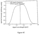
Figure 4C shows calculated amplification curves for optical parametric amplification for coupling-in at various amounts of angular dispersion [dashed line: without angular dispersion of the signal; continuous line: with angular dispersion of the signal according to the continuous line ofFigure 4B ] when assuming a crystal length of L = 5 mm. - In what follows, some exemplary embodiments of the compact optical device according to the invention are discussed in detail with reference to
Figures 1 to 3 . - The
optical device 100 according to the invention comprises anonlinear medium 107 having entrance andexit surfaces dispersive element 105 in optical coupling with theentrance surface 107a through anoptical contact 106. In theoptical device 100, the angulardispersive element 105 is coupled to thenonlinear medium 107 directly with no imaging optics inserted therebetween, apart from saidoptical contact 106. The angulardispersive element 105 is provided by e.g. at least one diffraction-based element (preferentially one or more optical gratings), or at least one refraction-based element (preferentially one or more prisms) or any combinations thereof (that is, e.g. a so-called grism or grating prism which is a prism combined with a grating). Theoptical contact 106 is provided by e.g. a short propagation distance in vacuum or in air, or a dielectric material (e.g. glass or an adhesive), or a composition of various dielectric materials (e.g. optical thin films) or any combinations thereof. When applied, theoptical contact 106 is chosen/formed so as to obtain such a propagation distance to be travelled by a beam with angular dispersion through saidoptical contact 106 which is sufficiently small in order that any further incidental beam expansion effects due to theoptical contact 106 be negligible from the point of view of the application concerned. - In a possible further embodiment, the angular
dispersive element 105 is formed directly on/in the surface of thenonlinear medium 107; in such a case there is nooptical contact 106. In a possible yet further embodiment, the angulardispersive element 105 is formed within the bulknonlinear medium 107 itself at a given depth from theentrance surface 107a along the beam propagation direction; there is no need for theoptical contact 106 in this case either. - The
optical device 100 serves for performing nonlinear optical processes. In what follows, the operation of saidoptical device 100 according to the invention is outlined in brief. To this end, optical parametric amplification and/or frequency conversion are/is considered as the nonlinear optical process. - An
input signal 102 coupled into theoptical device 100 through theentrance surface 107a is generated by a broadband and/or tunablesignal emission source 101. When saidsignal 102 is coupled into thenonlinear medium 107 through theoptical contact 106, said angulardispersive element 105 introduces an adequate amount of angular dispersion into thesignal 102. Here, thesignal 108 travelling within thenonlinear medium 107 interacts with apump beam 104 generated by apump source 103 and coupled also into thenonlinear medium 107. Anoutput signal 109 amplified or frequency converted via the nonlinear optical interaction that takes place within thenonlinear medium 107 exits saidnonlinear medium 107 through itsexit surface 107b. - A possible further embodiment of the optical device according to the invention is illustrated in
Figure 2 . Aninput signal 202 generated by a broadband and/or tunablesignal emission source 201 is coupled into thisoptical device 200. When saidsignal 202 is coupled directly into thenonlinear medium 206, an adequate amount of angular dispersion is induced in saidsignal 202 by an angulardispersive element 205. Thesignal 208 travelling in thenonlinear medium 206 interacts with apump beam 204 generated by apump source 203. Anoutput signal 209 amplified or frequency converted via the nonlinear optical interaction that takes place within thenonlinear medium 206 exits saidnonlinear medium 206, in this case through an angulardispersion compensating element 207 that is optically coupled with the exit surface of saidnonlinear medium 206. Thus, theoutput signal 209 no longer contains angular dispersion. It is noted that, similarly to the arrangement shown inFigure 1 , said angulardispersion compensating element 207 can be equally formed/arranged along the beam propagation direction downstream of said angulardispersive element 205 within thenonlinear medium 206 itself and/or on its exit surface. - A possible yet further embodiment of the optical device according to the invention is shown in
Figure 3 . Aninput signal 302 generated by a broadband and/or tunablesignal emission source 301 is coupled into thisoptical device 300. In this embodiment, theinput signal 302 reaches an angulardispersive element 306 when passing through acover medium 305. An adequate amount of angular dispersion is introduced into saidsignal 302 by said angulardispersive element 306 when saidsignal 302 enters thenonlinear medium 307. Thesignal 308 travelling within saidnonlinear medium 307 interacts with apump beam 304 generated by apump source 303. Anoutput signal 309 amplified or frequency converted via the nonlinear optical interaction exits saidnonlinear medium 307. - A practical embodiment of the optical device according to the invention is shown in
Figure 4A . Aninput signal 402 generated by a broadband and/or tunablesignal emission source 401 is coupled into thisoptical device 400. In this embodiment, an adequate amount of angular dispersion is introduced into saidsignal 402 by passing it through an angulardispersive element 405 comprising anoptical grating 411, awedge 410 and a furtheroptical grating 406 provided on the exit surface of saidwedge 410. After entering thenonlinear medium 407, thesignal 408 travelling within thenonlinear medium 407 interacts with a pump beam 404 generated by apump source 403. Anoutput signal 409 amplified or frequency converted via the nonlinear optical interaction exits saidnonlinear medium 407. - Reverting now to the
optical device 100 shown inFigure 1 , in the case of broadband parametric amplification, theinput signal 102 is typically a low-energy ultrashort light pulse. Thepump source 103 emits typically a short light pulse, the duration of which falls typically into the femtosecond, pikosecond or nanosecond range. Thenonlinear medium 107 is, for example, a birefringent nonlinear crystal (in particular, e.g. barium borate (BBO), lithium borate (LBO), potassium dihydrogen phosphate (KDP), deuterated potassium dihydrogen phosphate (DKDP), potassium titanyl phosphate (KTP), potassium titanyl arsenate (KTA), lithium niobate (LiNbO3) or any other suitable material) arranged in the light path with appropriate axis orientation, in which phase matching can be obtained at the central wavelength of the pump and the signal. Depending on the wavelengths employed and the material of the nonlinear crystal, said phase matching can be either collinear or non-collinear; specifically, for the optical device sketched inFigure 1 , non-collinear phase matching is attained. The bandwidth of a parametric amplifier is determined by the index of refraction of the nonlinear medium, besides beam direction. In many cases, the bandwidth can be remarkably increased by utilizing angular dispersion, as it is disclosed for the signal beam inU.S. Patent No. 6,741,388 B2 already cited. It is noted that in certain cases an adequate angular dispersion of the pump may result in an increase of the bandwidth if the pump beam is broadband enough (when e.g. the pulse duration falls into the femtosecond range). As it was already discussed, the devices suitable for introducing angular dispersion can be devices based on diffraction (e.g. optical grating(s)), devices based on refraction (e.g. prism(s)) or the combinations thereof. Due to angular dispersion, an initially collimated beam becomes divergent which is disadvantageous for most applications because as a consequence of e.g. an increased spot size the beam intensity decreases and the elliptic beam cross section impairs focusability. To eliminate these difficulties such an imaging optics has been applied earlier that imaged the output of the angular dispersive element to the input of the nonlinear crystal. Various image defects, however, led to beam distortions that limited the useful beam size. This limitation was particularly significant in systems of high power. - The operation of the embodiments of the optical device according to the invention illustrated in
Figures 1 to 3 andFigure 4A can be described in relation to further examples of broadband nonlinear optical processes, in particular for frequency conversion processes, similarly to the case of optical parametric amplification considered earlier. Such processes can be e.g. the sum and difference frequency generation, wherein the output signals 109, 209, 309, 409 are actually the frequency converted signals, as it is apparent to a person skilled in the art. In such processes, as in the case of optical parametric amplification, it is quite frequent that one of the input beams (typically thepump beam - The optical device according to the invention allows the construction of compact parametric amplification or frequency conversion devices. Contrary to the setups employing optical imaging elements (imaging optics), a further advantage of the optical device according to the invention is the lack of image defects. Due to this, larger beam sizes can be used that allows the inventive optical device to be used in laser systems of large power and the construction of such systems. Moreover, the optical device according to the invention can be used as a separate stage in multi-stage or hybrid optical parametric amplification systems (further details of such systems can be found e.g. in
U.S. Patent No. 6,870,664 B2 ,U.S. Patent No. 6,873,454 B2 ,U.S. Patent No. 6,791,743 B2 andU.S. Patent No. 6,775,053 ). - The optical device according to the invention can also be used in tunable and/or high power and/or ultrafast laser systems. By means of that, light sources suitable for e.g. laser electron acceleration, materials examination, spectroscopy can be constructed. A yet further field of utilization for such light sources is hadron therapy in the field of medical sciences which is based on high energy ion beams created by high intensity lasers.
- Furthermore, the optical device according to the invention allows the development of such high power laser systems, especially in the infrared wavelength range (e.g. about the wavelength of 1.5 µm), the pulse duration of which is shorter than what is achievable in this wavelength range by other techniques nowadays. It is an effective solution to apply diode-pumped solid-state lasers in a direct way, that is, without frequency conversion that decreases efficiency in said wavelength range for pumping the optical parametric amplifier. In high power systems, due to large beam sizes, only those crystals can be used from among the crystals suitable for optical parametric amplification or frequency conversion that can be manufactured with sufficiently large dimensions and good optical quality. Up to now, KTA and/or KTP crystals have been and are used for broadband optical parametric amplification in the near infrared range, e.g. in the vicinity of the wavelength of 1.5 µm (see e.g. the publication of O. D. Mücke et al. [Advances in Solid State Lasers Development and Applications, edited by M. Grishin, In-Tech, 2010]). Said crystals, however, are not available at present with large dimensions (i.e. with an aperture of 5 to 10 cm), and also exhibit relatively low nonlinear coefficients.
- Contrary to this, LiNbO3 crystals that are also available and/or can be manufactured with relatively large dimensions (∼ 10 cm) can be used in the optical device according to the invention advantageously, as it is shown in
Figures 4A, 4B and4C . In particular, in the case of a LiNbO3 crystal with a length of L = 5 mm, and for a pump wavelength of e.g. about 1 µm and a signal having a wavelength of about 1.5 µm, and for a case wherein the effective nonlinearity is much higher than the nonlinear coefficients of KTA/KTP crystals (pump with extraordinary polarization, ordinary signal and idler, i.e. exploiting the phase matching of p(e) -> s(o) + i(o)), a bandwidth of about 5 nm can be obtained at zero angular dispersion (see the dashed line ofFigure 4C ). If, however, the angular dispersion of the input signal is chosen in accordance with the solid line ofFigure 4B , the available bandwidth for the amplification can be increased above 200 nm, as it is represented by the amplification curve, indicated by a solid line, ofFigure 4C . Thus,Figure 4C clearly shows the advantage of the present invention: it provides about a forty-fold increase in the bandwidth. - Taking the above into consideration, an optical parametric amplifier that is efficient, compact and scalable for high powers can be constructed by means of the optical device according to the invention, in particular, for applications in the near infrared range if a LiNbO3 crystal is used as the nonlinear optical medium therein.
Claims (14)
- An optical device (100; 200; 300; 400) to perform nonlinear optical processes, the optical device comprises a nonlinear optical medium (107; 206; 307; 407) having an entrance surface and an exit surface, and an angular dispersive element (105; 205; 306; 405) in direct optical coupling with the nonlinear optical medium (107; 206; 307; 407) with no imaging optics inserted between the nonlinear optical medium (107; 206; 307; 407) and the angular dispersive element (105; 205; 306; 405), characterized in that the angular dispersive element (105; 205; 306; 405) directs each frequency component of a broadband incident light beam (102; 202; 302; 402) into its respective phase matching direction within the nonlinear medium (107; 206; 307; 407).
- The optical device according to Claim 1, characterized in that an element (207) with broadband angular dispersion compensating property is in optical coupling with the exit surface of the nonlinear medium (206).
- The optical device according to Claim 2, characterized in that said element (207) with angular dispersion compensating property is formed within the nonlinear medium (206) or on the exit surface thereof.
- The optical device according to any of Claims 1 to 3, characterized in that the broadband angular dispersive element (105; 205; 306; 405) is formed/arranged within the nonlinear medium (107; 206; 307; 407) or on the entrance surface (107a) thereof.
- The optical device according to any of Claims 1 to 4, characterized in that said broadband angular dispersive element (105; 205; 306; 405) is in the form of a diffraction- and/or refraction-based angular dispersive element.
- The optical device according to Claim 5, characterized in that said diffraction- and/or refraction-based broadband angular dispersive element is provided by at least one of: diffraction grating, prism, prism combined with a diffraction grating, i.e. grism.
- The optical device according to any of Claims 1 to 6, characterized in that said nonlinear medium (107; 206; 307; 407) is provided by at least one of: barium borate (BBO), lithium borate (LBO), potassium dihydrogen phosphate (KDP), deuterated potassium dihydrogen phosphate (DKDP), potassium titanyl phosphate (KTP), potassium titanyl arsenate (KTA), lithium niobate (LiNbO3) crystals or any combinations of the above crystals.
- The optical device according to Claim 7, characterized in that the nonlinear medium (107; 206; 307; 407) is provided by a LiNbO3 crystal.
- A method for performing a nonlinear optical process in a nonlinear optical medium (107; 206; 307; 407), wherein at least one coherent light beam is coupled into the nonlinear optical medium without being transmitted through an optical imaging system and then the coupled-in light beam is subjected to a nonlinear optical process via nonlinear optical interaction in the nonlinear medium, characterized in that the at least one light beam (102, 104; 202, 204; 302, 304; 402, 404) is a light beam with multispectral composition and that the coupling of said light beam into the nonlinear optical medium (107; 206; 307; 407) to perform the nonlinear optical process is carried out with introducing angular-dispersion-based achromatic extension of the phase-matching range into the at least one light beam, that is, directing each frequency component of said light beam through angular dispersive coupling-in simultaneously into its respective phase matching direction within the nonlinear medium (107; 206; 307; 407).
- The method according to Claim 9, characterized in that optical parametric amplification of ultrashort light pulses making up the light beam is performed as the nonlinear optical process.
- The method according to Claim 9, characterized in that frequency conversion of ultrashort light pulses making up the light beam is performed as the nonlinear optical process.
- The method according to any of Claims 9 to 11, characterized in that said angular dispersive coupling-in is completed by means of a diffraction- and/or refraction-based broadband angular dispersive element (105; 205; 306; 405).
- The method according to Claim 12, characterized in that the broadband angular dispersive element (105; 205; 306; 405) is formed/arranged within the nonlinear medium (107; 206; 307; 407) or on an entrance surface (107a) thereof.
- A coherent multispectral light source, characterized in that it comprises an optical device (100; 200; 300; 400) according to any of Claims 1 to 8.
Applications Claiming Priority (2)
| Application Number | Priority Date | Filing Date | Title |
|---|---|---|---|
| HU1000179A HU230314B1 (en) | 2010-04-07 | 2010-04-07 | Optical device for broadband nonlinear optical processes |
| PCT/HU2011/000031 WO2011124935A2 (en) | 2010-04-07 | 2011-04-07 | Optical device for broadband nonlinear optical processes based on angular dispersion |
Publications (2)
| Publication Number | Publication Date |
|---|---|
| EP2556407A2 EP2556407A2 (en) | 2013-02-13 |
| EP2556407B1 true EP2556407B1 (en) | 2019-07-10 |
Family
ID=89989646
Family Applications (1)
| Application Number | Title | Priority Date | Filing Date |
|---|---|---|---|
| EP11728658.3A Active EP2556407B1 (en) | 2010-04-07 | 2011-04-07 | Optical device for broadband nonlinear optical processes based on angular dispersion |
Country Status (3)
| Country | Link |
|---|---|
| EP (1) | EP2556407B1 (en) |
| HU (1) | HU230314B1 (en) |
| WO (1) | WO2011124935A2 (en) |
Citations (2)
| Publication number | Priority date | Publication date | Assignee | Title |
|---|---|---|---|---|
| US20030147122A1 (en) * | 2001-12-13 | 2003-08-07 | The Regents Of The University Of California | Coherent white light amplification |
| US20030227668A1 (en) * | 2002-04-09 | 2003-12-11 | Riken | Apparatus for generating tera-herz wave and tuning method |
Family Cites Families (6)
| Publication number | Priority date | Publication date | Assignee | Title |
|---|---|---|---|---|
| US6775053B2 (en) | 2001-04-12 | 2004-08-10 | The Regents Of The University Of California | High gain preamplifier based on optical parametric amplification |
| CN1172411C (en) * | 2001-04-18 | 2004-10-20 | 中国科学院理化技术研究所 | A nonlinear optical crystal laser frequency conversion coupler |
| CN1164966C (en) | 2001-08-01 | 2004-09-01 | 中国科学院理化技术研究所 | Nonlinear optical crystal laser frequency conversion grating coupler |
| US6791743B2 (en) | 2001-12-13 | 2004-09-14 | The Regents Of The University Of California | High average power scaling of optical parametric amplification through cascaded difference-frequency generators |
| US6873454B2 (en) | 2001-12-13 | 2005-03-29 | The Regents Of The University Of California | Hybrid chirped pulse amplification system |
| US6870664B2 (en) | 2001-12-13 | 2005-03-22 | The Regents Of The University Of California | Nondegenerate optical parametric chirped pulse amplifier |
-
2010
- 2010-04-07 HU HU1000179A patent/HU230314B1/en unknown
-
2011
- 2011-04-07 WO PCT/HU2011/000031 patent/WO2011124935A2/en not_active Ceased
- 2011-04-07 EP EP11728658.3A patent/EP2556407B1/en active Active
Patent Citations (2)
| Publication number | Priority date | Publication date | Assignee | Title |
|---|---|---|---|---|
| US20030147122A1 (en) * | 2001-12-13 | 2003-08-07 | The Regents Of The University Of California | Coherent white light amplification |
| US20030227668A1 (en) * | 2002-04-09 | 2003-12-11 | Riken | Apparatus for generating tera-herz wave and tuning method |
Also Published As
| Publication number | Publication date |
|---|---|
| EP2556407A2 (en) | 2013-02-13 |
| WO2011124935A2 (en) | 2011-10-13 |
| HUP1000179A2 (en) | 2011-11-28 |
| HU230314B1 (en) | 2016-01-28 |
| HU1000179D0 (en) | 2010-05-28 |
| WO2011124935A3 (en) | 2012-01-12 |
Similar Documents
| Publication | Publication Date | Title |
|---|---|---|
| US11762261B2 (en) | Parametric light generation method and its application | |
| JP3479735B2 (en) | Apparatus and generator for short optical pulse, and method for correcting nonlinear group velocity dispersion mismatch | |
| US7583431B2 (en) | Wavelength conversion optical device, laser light source, and image display optical device | |
| KR101633154B1 (en) | Arrangement and method for the frequency conversion of laser radiation | |
| WO2009108844A1 (en) | Methods and devices for generation of broadband pulsed radiation | |
| JP5130762B2 (en) | Broadband light source device | |
| JP2009543114A (en) | Spectral doubling-mediated chirped pulse amplifier using third-order dispersion chirping | |
| EP2887136B1 (en) | Nonlinear frequency conversion (NLFC) device and light source | |
| WO2009093425A1 (en) | Wide-band optical amplifier, optical pulse generator, and optical instrument | |
| US6288832B1 (en) | Apparatus and methods for using achromatic phase matching at high orders of dispersion | |
| US6870664B2 (en) | Nondegenerate optical parametric chirped pulse amplifier | |
| US6775053B2 (en) | High gain preamplifier based on optical parametric amplification | |
| Mero et al. | High-power, few-cycle, angular dispersion compensated mid-infrared pulses from a noncollinear optical parametric amplifier | |
| US20090180498A1 (en) | Coherent Beam Combiner Based on Parametric Conversion | |
| WO2006001838A2 (en) | Scalable harmonic laser source and method | |
| Bradler et al. | Broadband difference frequency mixing between visible and near-infrared pulses for few-cycle pulse generation with stable carrier-envelope phase | |
| JP4583770B2 (en) | Coherent light source | |
| US7035298B2 (en) | Frequency conversion efficiency | |
| CN103348286A (en) | Ultraviolet laser device | |
| US5852620A (en) | Tunable time plate | |
| JP2022085423A (en) | Laser light output device | |
| WO2011124935A2 (en) | Optical device for broadband nonlinear optical processes based on angular dispersion | |
| JP5388224B2 (en) | Coherent light source | |
| US6741388B2 (en) | Coherent white light amplification | |
| TWI395384B (en) | Uv light generator |
Legal Events
| Date | Code | Title | Description |
|---|---|---|---|
| PUAI | Public reference made under article 153(3) epc to a published international application that has entered the european phase |
Free format text: ORIGINAL CODE: 0009012 |
|
| 17P | Request for examination filed |
Effective date: 20121106 |
|
| AK | Designated contracting states |
Kind code of ref document: A2 Designated state(s): AL AT BE BG CH CY CZ DE DK EE ES FI FR GB GR HR HU IE IS IT LI LT LU LV MC MK MT NL NO PL PT RO RS SE SI SK SM TR |
|
| DAX | Request for extension of the european patent (deleted) | ||
| 17Q | First examination report despatched |
Effective date: 20160119 |
|
| GRAP | Despatch of communication of intention to grant a patent |
Free format text: ORIGINAL CODE: EPIDOSNIGR1 |
|
| STAA | Information on the status of an ep patent application or granted ep patent |
Free format text: STATUS: GRANT OF PATENT IS INTENDED |
|
| INTG | Intention to grant announced |
Effective date: 20190122 |
|
| GRAS | Grant fee paid |
Free format text: ORIGINAL CODE: EPIDOSNIGR3 |
|
| GRAA | (expected) grant |
Free format text: ORIGINAL CODE: 0009210 |
|
| STAA | Information on the status of an ep patent application or granted ep patent |
Free format text: STATUS: THE PATENT HAS BEEN GRANTED |
|
| AK | Designated contracting states |
Kind code of ref document: B1 Designated state(s): AL AT BE BG CH CY CZ DE DK EE ES FI FR GB GR HR HU IE IS IT LI LT LU LV MC MK MT NL NO PL PT RO RS SE SI SK SM TR |
|
| RAP1 | Party data changed (applicant data changed or rights of an application transferred) |
Owner name: PECSI TUDOMANYEGYETEM |
|
| REG | Reference to a national code |
Ref country code: GB Ref legal event code: FG4D |
|
| REG | Reference to a national code |
Ref country code: CH Ref legal event code: EP Ref country code: AT Ref legal event code: REF Ref document number: 1154204 Country of ref document: AT Kind code of ref document: T Effective date: 20190715 |
|
| REG | Reference to a national code |
Ref country code: IE Ref legal event code: FG4D |
|
| REG | Reference to a national code |
Ref country code: DE Ref legal event code: R096 Ref document number: 602011060345 Country of ref document: DE |
|
| REG | Reference to a national code |
Ref country code: NL Ref legal event code: MP Effective date: 20190710 |
|
| REG | Reference to a national code |
Ref country code: LT Ref legal event code: MG4D |
|
| REG | Reference to a national code |
Ref country code: AT Ref legal event code: MK05 Ref document number: 1154204 Country of ref document: AT Kind code of ref document: T Effective date: 20190710 |
|
| PG25 | Lapsed in a contracting state [announced via postgrant information from national office to epo] |
Ref country code: FI Free format text: LAPSE BECAUSE OF FAILURE TO SUBMIT A TRANSLATION OF THE DESCRIPTION OR TO PAY THE FEE WITHIN THE PRESCRIBED TIME-LIMIT Effective date: 20190710 Ref country code: BG Free format text: LAPSE BECAUSE OF FAILURE TO SUBMIT A TRANSLATION OF THE DESCRIPTION OR TO PAY THE FEE WITHIN THE PRESCRIBED TIME-LIMIT Effective date: 20191010 Ref country code: NO Free format text: LAPSE BECAUSE OF FAILURE TO SUBMIT A TRANSLATION OF THE DESCRIPTION OR TO PAY THE FEE WITHIN THE PRESCRIBED TIME-LIMIT Effective date: 20191010 Ref country code: SE Free format text: LAPSE BECAUSE OF FAILURE TO SUBMIT A TRANSLATION OF THE DESCRIPTION OR TO PAY THE FEE WITHIN THE PRESCRIBED TIME-LIMIT Effective date: 20190710 Ref country code: AT Free format text: LAPSE BECAUSE OF FAILURE TO SUBMIT A TRANSLATION OF THE DESCRIPTION OR TO PAY THE FEE WITHIN THE PRESCRIBED TIME-LIMIT Effective date: 20190710 Ref country code: NL Free format text: LAPSE BECAUSE OF FAILURE TO SUBMIT A TRANSLATION OF THE DESCRIPTION OR TO PAY THE FEE WITHIN THE PRESCRIBED TIME-LIMIT Effective date: 20190710 Ref country code: LT Free format text: LAPSE BECAUSE OF FAILURE TO SUBMIT A TRANSLATION OF THE DESCRIPTION OR TO PAY THE FEE WITHIN THE PRESCRIBED TIME-LIMIT Effective date: 20190710 Ref country code: HR Free format text: LAPSE BECAUSE OF FAILURE TO SUBMIT A TRANSLATION OF THE DESCRIPTION OR TO PAY THE FEE WITHIN THE PRESCRIBED TIME-LIMIT Effective date: 20190710 Ref country code: PT Free format text: LAPSE BECAUSE OF FAILURE TO SUBMIT A TRANSLATION OF THE DESCRIPTION OR TO PAY THE FEE WITHIN THE PRESCRIBED TIME-LIMIT Effective date: 20191111 |
|
| PG25 | Lapsed in a contracting state [announced via postgrant information from national office to epo] |
Ref country code: RS Free format text: LAPSE BECAUSE OF FAILURE TO SUBMIT A TRANSLATION OF THE DESCRIPTION OR TO PAY THE FEE WITHIN THE PRESCRIBED TIME-LIMIT Effective date: 20190710 Ref country code: AL Free format text: LAPSE BECAUSE OF FAILURE TO SUBMIT A TRANSLATION OF THE DESCRIPTION OR TO PAY THE FEE WITHIN THE PRESCRIBED TIME-LIMIT Effective date: 20190710 Ref country code: LV Free format text: LAPSE BECAUSE OF FAILURE TO SUBMIT A TRANSLATION OF THE DESCRIPTION OR TO PAY THE FEE WITHIN THE PRESCRIBED TIME-LIMIT Effective date: 20190710 Ref country code: GR Free format text: LAPSE BECAUSE OF FAILURE TO SUBMIT A TRANSLATION OF THE DESCRIPTION OR TO PAY THE FEE WITHIN THE PRESCRIBED TIME-LIMIT Effective date: 20191011 Ref country code: ES Free format text: LAPSE BECAUSE OF FAILURE TO SUBMIT A TRANSLATION OF THE DESCRIPTION OR TO PAY THE FEE WITHIN THE PRESCRIBED TIME-LIMIT Effective date: 20190710 Ref country code: IS Free format text: LAPSE BECAUSE OF FAILURE TO SUBMIT A TRANSLATION OF THE DESCRIPTION OR TO PAY THE FEE WITHIN THE PRESCRIBED TIME-LIMIT Effective date: 20191110 |
|
| REG | Reference to a national code |
Ref country code: CH Ref legal event code: NV Representative=s name: VALIPAT S.A. C/O BOVARD SA NEUCHATEL, CH |
|
| PG25 | Lapsed in a contracting state [announced via postgrant information from national office to epo] |
Ref country code: TR Free format text: LAPSE BECAUSE OF FAILURE TO SUBMIT A TRANSLATION OF THE DESCRIPTION OR TO PAY THE FEE WITHIN THE PRESCRIBED TIME-LIMIT Effective date: 20190710 |
|
| PG25 | Lapsed in a contracting state [announced via postgrant information from national office to epo] |
Ref country code: PL Free format text: LAPSE BECAUSE OF FAILURE TO SUBMIT A TRANSLATION OF THE DESCRIPTION OR TO PAY THE FEE WITHIN THE PRESCRIBED TIME-LIMIT Effective date: 20190710 Ref country code: DK Free format text: LAPSE BECAUSE OF FAILURE TO SUBMIT A TRANSLATION OF THE DESCRIPTION OR TO PAY THE FEE WITHIN THE PRESCRIBED TIME-LIMIT Effective date: 20190710 Ref country code: RO Free format text: LAPSE BECAUSE OF FAILURE TO SUBMIT A TRANSLATION OF THE DESCRIPTION OR TO PAY THE FEE WITHIN THE PRESCRIBED TIME-LIMIT Effective date: 20190710 Ref country code: IT Free format text: LAPSE BECAUSE OF FAILURE TO SUBMIT A TRANSLATION OF THE DESCRIPTION OR TO PAY THE FEE WITHIN THE PRESCRIBED TIME-LIMIT Effective date: 20190710 Ref country code: EE Free format text: LAPSE BECAUSE OF FAILURE TO SUBMIT A TRANSLATION OF THE DESCRIPTION OR TO PAY THE FEE WITHIN THE PRESCRIBED TIME-LIMIT Effective date: 20190710 |
|
| PG25 | Lapsed in a contracting state [announced via postgrant information from national office to epo] |
Ref country code: SM Free format text: LAPSE BECAUSE OF FAILURE TO SUBMIT A TRANSLATION OF THE DESCRIPTION OR TO PAY THE FEE WITHIN THE PRESCRIBED TIME-LIMIT Effective date: 20190710 Ref country code: CZ Free format text: LAPSE BECAUSE OF FAILURE TO SUBMIT A TRANSLATION OF THE DESCRIPTION OR TO PAY THE FEE WITHIN THE PRESCRIBED TIME-LIMIT Effective date: 20190710 Ref country code: IS Free format text: LAPSE BECAUSE OF FAILURE TO SUBMIT A TRANSLATION OF THE DESCRIPTION OR TO PAY THE FEE WITHIN THE PRESCRIBED TIME-LIMIT Effective date: 20200224 Ref country code: SK Free format text: LAPSE BECAUSE OF FAILURE TO SUBMIT A TRANSLATION OF THE DESCRIPTION OR TO PAY THE FEE WITHIN THE PRESCRIBED TIME-LIMIT Effective date: 20190710 |
|
| REG | Reference to a national code |
Ref country code: DE Ref legal event code: R097 Ref document number: 602011060345 Country of ref document: DE |
|
| PLBE | No opposition filed within time limit |
Free format text: ORIGINAL CODE: 0009261 |
|
| STAA | Information on the status of an ep patent application or granted ep patent |
Free format text: STATUS: NO OPPOSITION FILED WITHIN TIME LIMIT |
|
| PG2D | Information on lapse in contracting state deleted |
Ref country code: IS |
|
| 26N | No opposition filed |
Effective date: 20200603 |
|
| PG25 | Lapsed in a contracting state [announced via postgrant information from national office to epo] |
Ref country code: SI Free format text: LAPSE BECAUSE OF FAILURE TO SUBMIT A TRANSLATION OF THE DESCRIPTION OR TO PAY THE FEE WITHIN THE PRESCRIBED TIME-LIMIT Effective date: 20190710 |
|
| PG25 | Lapsed in a contracting state [announced via postgrant information from national office to epo] |
Ref country code: MC Free format text: LAPSE BECAUSE OF FAILURE TO SUBMIT A TRANSLATION OF THE DESCRIPTION OR TO PAY THE FEE WITHIN THE PRESCRIBED TIME-LIMIT Effective date: 20190710 |
|
| PG25 | Lapsed in a contracting state [announced via postgrant information from national office to epo] |
Ref country code: LU Free format text: LAPSE BECAUSE OF NON-PAYMENT OF DUE FEES Effective date: 20200407 |
|
| REG | Reference to a national code |
Ref country code: BE Ref legal event code: MM Effective date: 20200430 |
|
| PG25 | Lapsed in a contracting state [announced via postgrant information from national office to epo] |
Ref country code: BE Free format text: LAPSE BECAUSE OF NON-PAYMENT OF DUE FEES Effective date: 20200430 |
|
| PG25 | Lapsed in a contracting state [announced via postgrant information from national office to epo] |
Ref country code: IE Free format text: LAPSE BECAUSE OF NON-PAYMENT OF DUE FEES Effective date: 20200407 |
|
| PG25 | Lapsed in a contracting state [announced via postgrant information from national office to epo] |
Ref country code: MT Free format text: LAPSE BECAUSE OF FAILURE TO SUBMIT A TRANSLATION OF THE DESCRIPTION OR TO PAY THE FEE WITHIN THE PRESCRIBED TIME-LIMIT Effective date: 20190710 Ref country code: CY Free format text: LAPSE BECAUSE OF FAILURE TO SUBMIT A TRANSLATION OF THE DESCRIPTION OR TO PAY THE FEE WITHIN THE PRESCRIBED TIME-LIMIT Effective date: 20190710 |
|
| PG25 | Lapsed in a contracting state [announced via postgrant information from national office to epo] |
Ref country code: MK Free format text: LAPSE BECAUSE OF FAILURE TO SUBMIT A TRANSLATION OF THE DESCRIPTION OR TO PAY THE FEE WITHIN THE PRESCRIBED TIME-LIMIT Effective date: 20190710 |
|
| PGFP | Annual fee paid to national office [announced via postgrant information from national office to epo] |
Ref country code: GB Payment date: 20220425 Year of fee payment: 12 Ref country code: FR Payment date: 20220421 Year of fee payment: 12 |
|
| PGFP | Annual fee paid to national office [announced via postgrant information from national office to epo] |
Ref country code: CH Payment date: 20220421 Year of fee payment: 12 |
|
| REG | Reference to a national code |
Ref country code: CH Ref legal event code: PL |
|
| GBPC | Gb: european patent ceased through non-payment of renewal fee |
Effective date: 20230407 |
|
| PG25 | Lapsed in a contracting state [announced via postgrant information from national office to epo] |
Ref country code: GB Free format text: LAPSE BECAUSE OF NON-PAYMENT OF DUE FEES Effective date: 20230407 |
|
| PG25 | Lapsed in a contracting state [announced via postgrant information from national office to epo] |
Ref country code: LI Free format text: LAPSE BECAUSE OF NON-PAYMENT OF DUE FEES Effective date: 20230430 Ref country code: GB Free format text: LAPSE BECAUSE OF NON-PAYMENT OF DUE FEES Effective date: 20230407 Ref country code: FR Free format text: LAPSE BECAUSE OF NON-PAYMENT OF DUE FEES Effective date: 20230430 Ref country code: CH Free format text: LAPSE BECAUSE OF NON-PAYMENT OF DUE FEES Effective date: 20230430 |
|
| PGFP | Annual fee paid to national office [announced via postgrant information from national office to epo] |
Ref country code: DE Payment date: 20250422 Year of fee payment: 15 |