EP2556228B1 - Exhaust subsystem with polymer housing - Google Patents
Exhaust subsystem with polymer housing Download PDFInfo
- Publication number
- EP2556228B1 EP2556228B1 EP10848144.1A EP10848144A EP2556228B1 EP 2556228 B1 EP2556228 B1 EP 2556228B1 EP 10848144 A EP10848144 A EP 10848144A EP 2556228 B1 EP2556228 B1 EP 2556228B1
- Authority
- EP
- European Patent Office
- Prior art keywords
- liner
- exhaust
- exhaust subsystem
- subsystem
- passageway
- Prior art date
- Legal status (The legal status is an assumption and is not a legal conclusion. Google has not performed a legal analysis and makes no representation as to the accuracy of the status listed.)
- Active
Links
Images






Classifications
-
- F—MECHANICAL ENGINEERING; LIGHTING; HEATING; WEAPONS; BLASTING
- F16—ENGINEERING ELEMENTS AND UNITS; GENERAL MEASURES FOR PRODUCING AND MAINTAINING EFFECTIVE FUNCTIONING OF MACHINES OR INSTALLATIONS; THERMAL INSULATION IN GENERAL
- F16L—PIPES; JOINTS OR FITTINGS FOR PIPES; SUPPORTS FOR PIPES, CABLES OR PROTECTIVE TUBING; MEANS FOR THERMAL INSULATION IN GENERAL
- F16L9/00—Rigid pipes
- F16L9/14—Compound tubes, i.e. made of materials not wholly covered by any one of the preceding groups
-
- F—MECHANICAL ENGINEERING; LIGHTING; HEATING; WEAPONS; BLASTING
- F01—MACHINES OR ENGINES IN GENERAL; ENGINE PLANTS IN GENERAL; STEAM ENGINES
- F01N—GAS-FLOW SILENCERS OR EXHAUST APPARATUS FOR MACHINES OR ENGINES IN GENERAL; GAS-FLOW SILENCERS OR EXHAUST APPARATUS FOR INTERNAL-COMBUSTION ENGINES
- F01N1/00—Silencing apparatus characterised by method of silencing
- F01N1/24—Silencing apparatus characterised by method of silencing by using sound-absorbing materials
-
- F—MECHANICAL ENGINEERING; LIGHTING; HEATING; WEAPONS; BLASTING
- F01—MACHINES OR ENGINES IN GENERAL; ENGINE PLANTS IN GENERAL; STEAM ENGINES
- F01N—GAS-FLOW SILENCERS OR EXHAUST APPARATUS FOR MACHINES OR ENGINES IN GENERAL; GAS-FLOW SILENCERS OR EXHAUST APPARATUS FOR INTERNAL-COMBUSTION ENGINES
- F01N13/00—Exhaust or silencing apparatus characterised by constructional features
-
- F—MECHANICAL ENGINEERING; LIGHTING; HEATING; WEAPONS; BLASTING
- F01—MACHINES OR ENGINES IN GENERAL; ENGINE PLANTS IN GENERAL; STEAM ENGINES
- F01N—GAS-FLOW SILENCERS OR EXHAUST APPARATUS FOR MACHINES OR ENGINES IN GENERAL; GAS-FLOW SILENCERS OR EXHAUST APPARATUS FOR INTERNAL-COMBUSTION ENGINES
- F01N13/00—Exhaust or silencing apparatus characterised by constructional features
- F01N13/004—Exhaust or silencing apparatus characterised by constructional features specially adapted for marine propulsion, i.e. for receiving simultaneously engine exhaust gases and engine cooling water
- F01N13/005—Exhaust or silencing apparatus characterised by constructional features specially adapted for marine propulsion, i.e. for receiving simultaneously engine exhaust gases and engine cooling water with parts constructed of non-metallic material, e.g. of rubber
-
- F—MECHANICAL ENGINEERING; LIGHTING; HEATING; WEAPONS; BLASTING
- F01—MACHINES OR ENGINES IN GENERAL; ENGINE PLANTS IN GENERAL; STEAM ENGINES
- F01N—GAS-FLOW SILENCERS OR EXHAUST APPARATUS FOR MACHINES OR ENGINES IN GENERAL; GAS-FLOW SILENCERS OR EXHAUST APPARATUS FOR INTERNAL-COMBUSTION ENGINES
- F01N13/00—Exhaust or silencing apparatus characterised by constructional features
- F01N13/16—Selection of particular materials
Definitions
- the present invention relates generally to exhaust subsystems formed, at least in part, of polymeric materials.
- Vehicle exhaust assemblies are typically formed of sheet metal or stainless steel to allow the transport of hot exhaust gases from a combustion engine away from the vehicle.
- Such exhaust assemblies typically include one or more volume mufflers, designed to absorb and dissipate acoustic and thermal energy.
- Metal is typically primarily used to allow the exhaust system to withstand high temperatures, and transfer heat away in the gases away from the vehicle.
- EP360044A1 and US4880078A disclose exhaust subsystems comprising an exterior pipe.
- Metal of course, has its limitations: it is somewhat cumbersome to form; it is heavy; and bulky. Also the shapes that can be formed are somewhat limited. Further, it is prone to corrosion.
- a exhaust subsystem includes an exterior pipe comprising polymer for carrying gases from an engine.
- a rigid liner within the exterior pipe extends along a length of the exhaust subsystem and defines a passageway having a periphery.
- a fiber insulating layer is formed between the rigid liner and the exterior pipe.
- the liner is formed to define at least one groove circumscribing the periphery of the passageway. The groove defines a region of increased cross-sectional area of the passageway along the length.
- the liner is further formed to define at least one void extending between the liner and the insulating layer, around the periphery of the passageway.
- the liner comprises a plurality of apertures in communication with the void, allowing sound waves to pass from the passageway into the fiber insulating layer, and into the void.
- An exhaust subsystem comprises: an exterior pipe comprising polymer, defining an exhaust passage along a length of the exterior pipe, for carrying gases from an engine; a rigid liner within the exterior pipe, extending along the length, defining a passageway having a periphery; and a fiber insulating layer formed between the rigid liner and the exterior pipe.
- the liner is formed to define at least one void extending between the liner and the insulating layer, around the periphery of the passageway and comprises a plurality of apertures, allowing sound waves to pass from the exhaust passage into the fiber insulating layer, and into the at least one void.
- FIG. 1 illustrates a vehicle 10 which includes an exhaust assembly 12 , formed of two separate exhaust subsystems: a forward exhaust subsystem 14 formed predominantly of metal exhaust components, in the form of stainless steel, steel, iron, nickel and the like; and an aft exhaust subsystem 16 , having a polymeric exterior housing, exemplary of an embodiment of the present invention.
- a forward exhaust subsystem 14 formed predominantly of metal exhaust components, in the form of stainless steel, steel, iron, nickel and the like
- aft exhaust subsystem 16 having a polymeric exterior housing, exemplary of an embodiment of the present invention.
- vehicle 10 includes an internal combustion engine 18 , located forward of a passenger compartment 20 .
- Exhaust assembly 12 interconnects to internal combustion engine 18 and guides exhaust gases from internal combustion engine 18 to the rear of vehicle 10 , allowing those gases to exhaust away from vehicle 10 .
- Forward exhaust subsystem 14 is in fluid communication with internal combustion engine 18 , and may include one or more exhaust components, such as exhaust manifolds 22 , catalytic convertors/particle filters 24 , and one or more metal pipes 26 emanating from internal combustion engine 18 and connected in flow series.
- Forward exhaust subsystem 14 is further in flow communication with aft exhaust subsystem 16 .
- Aft exhaust subsystem 16 is located downstream of forward exhaust subsystem 14 , in the direction of exhaust flow.
- Exhaust subsystems 14 , 16 are physically mounted to the vehicle in a conventional manner, for example, by being suspended from the chassis of vehicle 10 .
- Forward exhaust subsystem 14 may define one or more flow paths 28 between internal combustion engine 18 and aft exhaust subsystem 16 . As illustrated, forward exhaust subsystem 14 may provide a discrete flow path 28 on each side of internal combustion engine 18 to aft exhaust subsystem 16 . Multiple flow paths 28 may converge to a single path to feed aft exhaust subsystem 16 .
- Aft exhaust subsystem 16 includes one or more coupling assembly(ies) 30 which connect forward exhaust subsystem 14 with aft exhaust subsystem 16 .
- Coupling assemblies 30 are typically also formed of metal, and provide an interface between the substantially polymeric components of aft exhaust subsystem 16 and forward exhaust subsystem 14 .
- coupling assembly 30 is located downstream of the catalytic convertor/particle filter 24 of vehicle 10 .
- coupling assembly 30 may be located anywhere downstream of exhaust manifold 22 of vehicle 10 .
- Aft exhaust subsystem 16 is housed in a non-metal exterior pipe 32 .
- exterior pipe 32 is cylindrical in cross-section, and may be of a constant diameter. However, exterior pipe 32 may be of any arbitrary cross-section. Exterior pipe 32 defines an interior passage 34 for the transport of exhaust gases to outlet 36 of vehicle 10 .
- Aft exhaust subsystem 16 may include one or more sound attenuation regions 38 downstream of coupling assembly 30 . Sound attenuation regions 38 may extend from coupling assembly 30 to the exhaust outlet 36 , or may extend along the length of exterior pipe 32 at discrete intervals along the length of aft exhaust subsystem 16 .
- aft exhaust subsystem 16 is formed of four or more distinct layers, as best illustrated in FIGS. 2 and 3 : an exterior pipe 32 ; a thermal reflective coating 33 applied to the inner wall of exterior pipe 32 , an acoustic insulation layer 40 formed interior to exterior pipe 32 ; and a liner 42 , located between interior passage 34 and liner 42 .
- Acoustic insulation layer 40 and liner 42 extend along the length of interior passage 34 , and may extend substantially along the length of aft exhaust subsystem 16 .
- Exterior pipe 32 may be formed in whole or in part of a polymer material, such as a polyester, ethylene terepthelate, or the like, or composites thereof.
- Thermal reflective coating 33 may be a thin double-layer foil of melamine and heat-reflective paint, and may be applied to exterior pipe 32 during the plastic forming process. However, thermal reflective coating 33 may be any thin coating with suitable thermal properties, known to those of ordinary skill, and may be applied to the interior of exterior pipe 32 , after formation of exterior pipe 32 .
- the diameter of exterior pipe 32 is between approximately 70 mm and 100 mm; the thickness of thermal reflective coating 33 is between approximately 0.2 mm and 0.5 mm; the diameter of liner 42 is between approximately 40 mm and 60 mm; the thickness of liner 42 is between approximately 0.5 mm and 2.5 mm and the thickness of acoustic insulation layer 40 is between about 10 mm and 30 mm.
- These dimensions may be chosen based on the size and type of internal combustion engine 18 , the flow rate and temperature of gas to be exhausted, and the frequencies of sound that are being attenuated.
- the arrangement of insulation layer 40 ; and liner 42 allow the formation of sound attenuation regions 38 , along the length of exterior pipe 32 .
- liner 42 is located radially outward of interior passage 34 , and retains or supports acoustic insulation layer 40 against the inner wall of exterior pipe 32 .
- Liner 42 further provides fluid communication between interior passage 34 and acoustic insulation layer 40 , allowing sound waves to pass into acoustic insulation layer 40 .
- Acoustic insulation layer 40 is preferably formed of mineral fiber insulation to provide for acoustic and thermal insulation, but may be any type of insulation material or combination of materials with sufficient thermal and acoustic insulation properties, such as glass fiber.
- the depicted liner 42 has the same cross-sectional shape as exterior pipe 32 .
- liner 42 and exterior pipe 32 may have different cross-sectional shapes, provided liner 42 fits inside exterior pipe 32 , around interior passage 34 .
- liner 42 may have differing cross-sectional sizes, at various axial positions along passage 34 .
- liner 42 is made from stainless steel so that its shape is self-supporting.
- suitable materials including plastics, composites or the like, will be appreciated by those of ordinary skill.
- it may be made from other metal materials, provided they are of sufficient strength for the shape to be self-supporting.
- liner 42 includes a plurality of perforations 46 .
- Liner 42 may be formed from a generally flat sheet as depicted in FIG. 6 , and rolled into a lengthwise extending cylindrical tube, as further described.
- perforations 46 are formed throughout the surface 62 of liner 42 .
- Perforations 46 may be of a consistent size and shape, or may be of a number of different sizes and shapes. Perforations 46 may be evenly spaced, or the spacing may be varied. In particular, as will be discussed below, the relationship between the size and spacing of perforations 46 and the dimensions of grooves 48 or voids 50 may affect the acoustic performance of exhaust subsystem. Thus, the size and spacing of perforations 46 may be selected to maximize attenuation of sounds in certain frequency ranges.
- Perforations 46 in liner 42 create absorption regions along the length of interior passage 34 . More specifically, energy in the form of acoustic and thermal energy within the exhaust gases passes through perforations 46 into acoustic/thermal insulation layer 40 , where it may be substantially absorbed by the material forming acoustic/thermal insulation layer 40 . Conveniently, such absorption regions may be located at curves in the exhaust for improved acoustic performance; however absorption regions may be located anywhere along the length of interior passage 34 .
- Liner 42 may further define a series of grooves 48 and voids 50 extending around periphery of interior passage 34 in each sound attenuation region 38 , to further assist in attenuating engine and exhaust noise.
- each of voids 50 take the form of an annular cavity between liner 42 and insulation layer 40 .
- Each of voids 50 is formed by two opposing annular ribs 52 which extend radially outward from passageway 34 and hold insulation 40 away from liner 42 .
- ribs 52 are formed from liner 42 .
- Ribs 52 may, for example be formed by folding or pinching liner twice into overlapping relationship (example fold lines are shown in FIG. 6 ). However, ribs 52 could be formed in other ways.
- Insulation layer 40 is pre-formed into the required shape and wrapped around liner 42 .
- the pre-forming, along with ribs 52 ensures that the material of insulation layer 40 is held taut between ribs 52 .
- the resulting voids 50 define resonance chambers 54 bounded on the radially inward surface by liner 42 , on the radially outward surface by acoustic insulation layer 40 , and at the ends by ribs 52 .
- Each resonance chamber 54 has a width, measured along the length of passageway 34 and a depth, measured in the radial direction of aft exhaust subsystem 16 .
- Resonance chambers 54 may be annular in shape, or may be formed in alternative shapes and orientations. Resonance chambers 54 may be of a consistent length, depth and shape, or there may be resonance chambers 54 of multiple shapes and dimensions.
- the effective radius r may be used for a perforation 46 which is non-circular.
- aft exhaust subsystem 16 may be designed by selecting parameters A, r and t o to attenuate specific frequencies, as required or desired as a result of frequencies by engine 18 . That is for any particular engine 18 , and desired acoustic properties, A, r and t o , may be chosen and one or more resonance chambers 54 may be placed along the passage 34 .
- Resonance chambers 54 may be located at any point, or at multiple points along the axis of aft exhaust subsystem 16 .
- a resonance chamber 54 which is tuned to attenuate sounds at a particular frequency should be located at a distance from the inlet of aft exhaust subsystem 16 equivalent to at least one quarter of the wavelength corresponding to a sound wave at the particular frequency. This placement may ensure that resonance chamber 54 is exposed to the peak pressure created by the sound wave, maximizing the amplitude of the resonant vibration.
- Resonance chambers placed less than one quarter wavelength away from exhaust manifold 22 will typically not be exposed to such peak pressures, as will be appreciated, this will result in decreased effectiveness.
- Sound attenuation region 38 also includes one or more grooves 48 on the radially inward side of liner 42 , around the periphery of passage 34 defining expansion regions 64 .
- grooves 48 may be formed as generally annular deformations in liner 42 .
- Each groove 48 may be defined by two opposing annular walls 56 , each defined by two sharp bends 58 and 60 in liner 42 .
- the resulting expansion regions 64 have a width, measured along the length of interior passage 34 of aft exhaust subsystem 16 and a depth, measured in the radial direction of aft exhaust subsystem 16 .
- grooves 48 may be annular in shape, or may be formed in alternative shapes. Similarly, grooves 48 may be of a consistent length, depth and shape, or there may be grooves 48 of multiple shapes and dimensions.
- Expansion regions 64 are effective at attenuating lower frequency sounds than those attenuated in resonance chambers 54 . Further, expansion regions 64 of large volume attenuate lower frequencies than expansion regions 64 which are smaller in volume. The optimal dimensions of an expansion region 64 can again be determined heuristically or by computer simulation, given a particular frequency of interest and a particular diameter of passage 34 .
- Expansion regions 64 may be located at any point along passage 34 of aft exhaust subsystem 16 . Preferably, expansion regions 64 are located anywhere in aft exhaust subsystem 16 where there are no resonance chambers 54 . Expansion regions 64 which are intended to attenuate sounds at a particular frequency are preferably located at a distance from the inlet of aft exhaust subsystem 16 of at least one-quarter of the wavelength corresponding to that frequency.
- exterior pipe 32 may be injection or extrusion molded. As illustrated in FIG. 7 , exterior pipe 32 may be fabricated by forming a clam shell 80 .
- Shell 80 may be formed by injection-molding, extrusion, blow molding, or any other polymer manufacturing process.
- Clam shell 80 includes two half-shells that may that may be joined together. In the depicted embodiment, the half-shells may be injection-molded as a single shell 80 , joined at their inner edge by hinge 82 .
- Hinge 82 may be formed by molding the connection between the two halves of clam shell 80 as a thin wall portion, as more particularly illustrated in FIG. 8 .
- Outer edges 84 and 86 of shell 80 may include elements that engage to lock shell 80 into a cylinder to form exterior pipe 32 .
- each end of shell 80 includes a complementary lock portion.
- one end may be formed to include a lock socket 88 that may receive a complementary lock edge 86 having a retaining nib 90 .
- Nib 90 may be received in a groove of lock socket 88 , to retain lock edge 86 in lock socket 88 .
- the lock may be glued or welded shut.
- exhaust subsystem 16 may be formed by injection molding exterior pipe 32 , as clamshell 80 ; filling clamshell 80 with a layer of fibrous insulation to form insulation layer 40 ; and inserting liner 42 and optionally pipe 44 . Once the insulation, liner 42 and pipe 44 are contained within clamshell 80 , it may be closed and locked.
- exhaust subsystem 16 may further include an interior pipe 44 .
- Interior pipe 44 may be a conventional metal pipe, defining passage 34' parallel to exterior pipe 32 .
- Pipe 44 may be spaced from liner 42 by radially-extending discs (not shown) which support pipe 44 on liner 42 and which are attached to liner 42 by conventional means, for example, welding or crimping. The spacing of pipe 44 from liner 42 defines a void 45 between liner 42 and pipe 44 .
- Pipe 44 may include multiple apertures 47 through which void 45 is in fluid communication with passage 34' . Apertures 47 may optionally be provided with extensions 49 , having a height in the radial direction. Void 45 forms a resonance chamber analogous to resonance chambers 54 .
- apertures 47 may be surrounded by cylindrical extensions 49 .
- Extensions 49 increase the effective volume of air which interacts with the air in void 45 , causing it to resonate.
- the frequency at which the system resonates will be reduced as a result the addition of extensions 49 . If all apertures 47 are surrounded by extensions 49 of a particular height measured in the radial direction, that height will replace the term t o in the above relationship. If only some of apertures 47 are surrounded by extensions 49 , the frequency at which the air in void 45 resonates may be determined heuristically.
- aft exhaust subsystem 16 may further include a volume muffler 66 , depicted in FIGS. 12 and 13 .
- Volume muffler 66 additionally includes a non-metal (e.g. polymeric) muffler housing 70 .
- Muffler housing 70 may retain an interior metal pipe 71 (best viewed in FIG. 12 ).
- the pipe may be an extension of pipe 44 ( FIG. 10 ) having apertures 47' and/or extensions 49 ' along its length, or may be another pipe segment that may be interconnected with/in flow communication with pipe 44 or passage 34 .
- a catalytic convertor or particulate filter 74 may be contained in housing 70 proximate the inlet to volume muffler 66 .
- Pipe 71 in muffler housing 70 may be surrounded by a mesh 68 , spaced radially outward from pipe 71 .
- the gap between pipe 71 and mesh 68 , and the apertures in pipe 71 interact to form a resonance chamber akin to that of the embodiment depicted in FIG. 10 .
- Fibrous insulation may fill the region between mesh 68 and housing 70 .
- housing 70 may include lengthwise extending ribs 72 , providing structural rigidity to muffler housing 70 .
- Each rib 72 may be generally rectangular, defined by an arced wall portion and opposing, radially extending walls.
- Housing 70 may be extrusion or injection molded.
- volume muffler 66 has a generally circular cross-section with protruding ribs. However, volume muffler 66 may be formed in any arbitrary shape.
- aft exhaust subsystem 16 may include a volume muffler 76 which includes a housing 78 , insulation 80 (like insulation layer 40 ), and a liner 82 (like liner 42 ).
- Liner 82 may define a passage 84 through the lengthwise extent of volume muffler 76 .
- Resonance chambers 86 like resonance chambers 54
- expansion regions 88 like expansion regions 64
- Insulation 80 may fill the region between housing 78 and liner 82 .
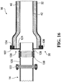
- Coupling assembly 30 used to connect aft subsystem 16 to forward subsystem 14 is more particularly illustrated in FIG. 16 .
- Coupling assembly 30 may attach to forward subsystem 14 at any suitable location downstream of exhaust manifold 22 of vehicle 10 .
- coupling assembly 30 includes a metal pipe stub 120 that is attached, for example, by welding, at its upstream end to a metallic upstream flange 122 .
- Upstream flange 122 allows for metal-to-metal flange connection by abutting a complementary flange on forward subsystem 14 thereby sealingly attaching aft exhaust subsystem 16 in fluid communication to forward subsystem 14 .
- Upstream flange 122 is mechanically affixed using a conventional fastener, locking the position of coupling assembly 30 , and thus aft exhaust subsystem 16 , to upstream forward exhaust subsystem 14 .
- Metal pipe stub 120 is attached at its other end, for example, by welding, to a thin metal flange 124 , proximate the downstream end of metal pipe stub 126 .
- Thin metal flange 124 should be thin - possibly as thin as possible, while remaining rigid. Typically, thin metal flange 124 is approximately 1.5 mm thick.
- Metal flange 124 connects coupling assembly 30 in fluid communication with exterior pipe 32 .
- Thin metal flange 124 has a small flange-pipe surface area 126 in direct contact with metal pipe 120 and a large convective surface area 128 in contact with ambient air. The large size of convective surface area 128 relative flange-pipe surface area 126 , promotes heat dissipation to ambient air.
- Thin metal flange 124 further includes an annular collar 130 extending axially in the downstream direction, which engages a retaining ring 132 .
- Retaining ring 132 engages a set of tabs 134 on the outer surface of exterior pipe 32 .
- Tabs 134 lock the axial and rotational position of exterior pipe 32 relative to coupling assembly 30 .
- two separate sets of tabs may be used, with one set to lock the axial position of exterior pipe 32 , and one set to lock the rotational position of exterior pipe 32 .
- Metal pipe stub 120 may extend downstream of thin metal flange 124 in the axial direction.
- the downstream end of metal pipe stub 120 may be shaped to enhance the fluid mechanic properties of exhaust gases entering exhaust subsystem.
- metal pipe stub 120 may terminate in a converging or diverging nozzle.
- metal pipe stub 120 may be extremely hot. In certain operating conditions, metal pipe stub 120 may reach temperatures in excess of 600 °C. Exposure to such high temperatures could damage exterior pipe 32 . For example, if placed in direct thermal contact with metal pipe stub 120 , exterior pipe 32 could melt.
- metal flange 120 provides thermal protection of exterior pipe 32 .
- the quantity of conduction from metal pipe stub 120 to thin metal flange 120 is limited by small size of flange-pipe surface area 126 .
- the area of convective surface 128 is large relative to flange-pipe surface area 126 .
- a significant quantity of the heat transferred into thin metal flange 124 by conduction from metal pipe 120 is transferred to ambient air, rather than being conducted to exterior pipe 32 .
- Metal pipe stub 120 may further include an accordion-like bellows section 138 located upstream of thin metal flange 124 .
- Bellows section 138 may be capable of deforming in an axial direction, to absorb mechanical and thermal stresses. Conveniently, bellows section 138 prevents axial vibrations from being transmitted to exhaust subsystem 16 from engine 18 and forward exhaust subsystem 14 .
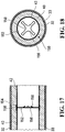
- exhaust subsystem 16 may also include one or more baffles 150 within passage 34 along its length, depicted in FIGS. 17 and 18 .
- Baffles 150 may be located proximate the upstream end of exhaust subsystem 16 , or may be located at any point.
- Baffles 150 include a face 152 positioned generally normal to the flow of gases through passage 34 and a baffle flange 154 attached to liner 42 by conventional means, for example, by spot welding. Face 152 has an aperture 156 which allows exhaust gases to pass through baffle 150 and which defines one or more lobes 158 in face 152 .
- Baffles 150 may be constructed of a metal material, for example, stainless steel or spring steel.
- lobes 158 The material, thickness and shape of lobes 158 is chosen so that lobes 158 resonate at a particular frequency. Sound waves of this frequency in passage 34 cause the lobes to vibrate. This resonant vibration causes an out of phase pressure wave to propagate in the upstream direction of the pipe, destructively interfering with waves of the particular frequency.
- the material, thickness and shape of the lobes is also chosen so that pressure from exhaust gases can cause lobes 158 to deflect in the downstream direction as illustrated in FIG. 14 . When lobes 158 deflect, the size of aperture 156 increases, allowing exhaust gases to pass through baffle 150 more easily.
- engine 18 produces high-temperature and pressure and expels exhaust gases. Exhaust gases travel through sealed exhaust subsystem 14 . Partially cooled exhaust gases exit from subsystem 14 into aft exhaust subsystem 16 by way of coupling assembly 30 .
- exhaust gases As exhaust gases propagate along passage 34 , exhaust gases gradually cool by transferring heat to exhaust subsystem 16 , and more particularly to insulation layer 40 , which resists heat transfer toward exterior pipe 32 .
- insulation layer 40 may provide sufficient thermal protection, to ensure that heat absorbed from the exhaust gases does not cause exterior pipe 32 to melt or materially deform, insulation 40 limits the amount of heat that may be transferred from the exhaust gases to exhaust subsystem 16 . As a consequence, exhaust gases exiting exhaust subsystem 16 exit at higher temperatures than they would in the absence of insulation layer 40 . With modern combustion engines, this remains acceptable as such engines produce lower temperature exhaust gases.
- engine 18 in operation, also causes sound waves to propagate down exhaust passage 34 .
- the sounds created by engine 18 may be particularly loud within a certain characteristic frequency range, which is determined by factors including the operating speed (revolutions per minute), number of cylinders and configuration of cylinders of engine 18 .
- Sound waves are created by pulses of high pressure emitted from engine 18 , which pass through upstream subsystem 14 to and through exhaust subsystem 16 .
- the sound waves may be attenuated in several ways. Specifically, the sound waves may be attenuated by absorption regions along passage 34 ; resonance chambers 54 ; expansion regions 64 ; or by baffles 150 .
- absorption regions sound waves propagating along passage 34 may pass through perforations 46 in liner 42 and into insulation layer 40 . Sound waves entering insulation layer 40 in this manner are absorbed and the energy associated with such waves is dissipated by insulation layer 40 .
- the performance of absorption regions is dependent on their location in exhaust subsystem 16 . Absorption regions located in curved sections of exhaust subsystem 16 may be more effective at attenuating sound as sound waves in such curved sections may travel directly into insulation layer 40 . Conversely, where passage 34 is aligned with the average direction of propagation of sound waves, waves can enter insulation layer 40 in a direction normal to the direction of the wave's propagation.
- expansion regions 64 the cross-sectional area of interior passage 34 is increased, slowing down the flow of exhaust gases. This improves the effectiveness of sound attenuation insulation layer 40 adjacent to expansion regions 64 .
- Attenuation of sound by absorption in this manner is particularly effective for high-frequency sounds.
- the waves excite the air in perforations 46 , which causes the air inside resonance chambers 54 to resonate. More specifically, sound waves induce Helmholtz resonance at a particular frequency in resonance chambers 54 . As set out above, the frequency of this resonance is dependent on the volume of resonance chamber 54 , the number and area of perforations 46 through which resonance chamber 54 is in fluid communication with interior passage 34 , and the thickness of liner 42 . Resonance of the air in resonance chambers 54 causes destructive interference with, and thus attenuates sound waves of the same frequency in interior passage 34 .
- Sound waves in interior passage 34 also cause air in expansion regions 64 to reflect and /or resonate. Reflection/resonance in expansion regions 64 occurs at low frequencies, for example, less than 500 Hz, less than 300 Hz or less than 200 Hz.
- lobes 158 are designed such that they resonate at a particular frequency. Resonance of lobes 158 causes waves of the same frequency to propagate along the interior passage 34 , in the upstream direction. These waves destructively interfere with waves of the same frequency originating from engine 18 , and thus, attenuate sound at that frequency.
- each baffle 150 has lobes 158 and at least one aperture 156 .
- Aperture 156 permits exhaust gases to flow through baffle 150 .
- the flow rate of exhaust gases increases.
- baffle 150 may restrict flow. When this occurs, pressure will increase upstream of baffle 150 , causing lobes 158 to deflect in the downstream direction, increasing the size of aperture 168 and reducing the restriction on gas flow.
- the sound attenuation resulting from the resonance of lobes 158 may be reduced when lobes 158 are deflected in this manner.
- lobes 158 may be tuned for attenuation of low frequency sounds, which are prevalent at low engine speeds, when the flow rate of exhaust gas is comparatively low. At higher engine speeds, when higher frequency sounds are predominant, increased exhaust gas flow will cause lobes 158 to deflect, reducing the backpressure created by baffles 150 .
- the overall acoustic properties of exhaust subsystem 16 can be customized for application to a specific engine 16 .
- Each of the baffles 150 , resonance chambers 54 and expansion regions 64 can be specifically tuned as described above to attenuate sounds in a particular range of frequencies.
- subsystem 16 may extend all the way to the exhaust system exit, and may obviate the need for a volume muffler. Conveniently, sound attenuation may occur all the way along the length.
Landscapes
- Engineering & Computer Science (AREA)
- General Engineering & Computer Science (AREA)
- Mechanical Engineering (AREA)
- Chemical & Material Sciences (AREA)
- Combustion & Propulsion (AREA)
- Ocean & Marine Engineering (AREA)
- Exhaust Silencers (AREA)
Description
- The present invention relates generally to exhaust subsystems formed, at least in part, of polymeric materials.
- Vehicle exhaust assemblies are typically formed of sheet metal or stainless steel to allow the transport of hot exhaust gases from a combustion engine away from the vehicle. Such exhaust assemblies typically include one or more volume mufflers, designed to absorb and dissipate acoustic and thermal energy. Metal is typically primarily used to allow the exhaust system to withstand high temperatures, and transfer heat away in the gases away from the vehicle.
EP360044A1 US4880078A disclose exhaust subsystems comprising an exterior pipe. - Metal, of course, has its limitations: it is somewhat cumbersome to form; it is heavy; and bulky. Also the shapes that can be formed are somewhat limited. Further, it is prone to corrosion.
- More recently, synthetic materials, such as polymers, have been introduced into vehicle exhaust assemblies. The polymer material is less costly, lighter, and less susceptible to corrosion. At the same time, such materials are typically less able to dissipate heat.
- Nevertheless exhaust systems that incorporate synthetic materials are in early stages of development. Accordingly, there remains a need for exhaust systems and subsystems that take advantage of synthetic materials.
- In an embodiment, a exhaust subsystem includes an exterior pipe comprising polymer for carrying gases from an engine. A rigid liner within the exterior pipe extends along a length of the exhaust subsystem and defines a passageway having a periphery. A fiber insulating layer is formed between the rigid liner and the exterior pipe. The liner is formed to define at least one groove circumscribing the periphery of the passageway. The groove defines a region of increased cross-sectional area of the passageway along the length. The liner is further formed to define at least one void extending between the liner and the insulating layer, around the periphery of the passageway. The liner comprises a plurality of apertures in communication with the void, allowing sound waves to pass from the passageway into the fiber insulating layer, and into the void.
- An exhaust subsystem comprises: an exterior pipe comprising polymer, defining an exhaust passage along a length of the exterior pipe, for carrying gases from an engine; a rigid liner within the exterior pipe, extending along the length, defining a passageway having a periphery; and a fiber insulating layer formed between the rigid liner and the exterior pipe. The liner is formed to define at least one void extending between the liner and the insulating layer, around the periphery of the passageway and comprises a plurality of apertures, allowing sound waves to pass from the exhaust passage into the fiber insulating layer, and into the at least one void.
- Other aspects and features of the present invention will become apparent to those of ordinary skill in the art upon review of the following description of specific embodiments of the invention in conjunction with the accompanying figures.
- In the figures which illustrate by way of example only, embodiments of the present invention,
-
FIG. 1 is a schematic view of a vehicle including an exhaust assembly and exhaust subsystem, exemplary of an embodiment of the present invention; -
FIG. 2 is an end perspective view of an exhaust subsystem ofFIG. 1 ; -
FIG. 3 is a cross-sectional view of the exhaust subsystem ofFIG. 1 at III-III ; -
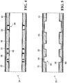
FIGS. 4 and 5 are axial cross-sectional views of a portion of the exhaust subsystem ofFIG. 2 ; -
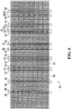
FIG. 6 is a plan of a liner forming part of the exhaust subsystem ofFIG. 2 ; -
FIGS. 7 to 9 are cross-sectional views of the exterior shell of the exhaust subsystem ofFIG. 2 ; -
FIG. 10 an end view of an alternative exhaust subsystem, exemplary of an embodiment of the present invention; -
FIG. 11 is an axial cross-sectional views of a portion of the exhaust subsystem ofFIG. 10 ; -
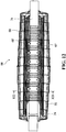
FIGS. 12 is an axial cross-section of a volume muffler that may form part of the exhaust subsystem ofFIG. 2 ; -
FIG. 13 is a radial cross-section of the volume muffler ofFIG. 12 ; -
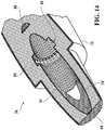
FIG. 14 is a partial cut-away perspective view of a further volume muffler that may form part of the exhaust subsystem ofFIG. 2 ; -
FIG 15 is an axial cross-sectional view of the volume muffler ofFIG. 14 . -
FIG. 16 is a cross-sectional view of a portion of the exhaust subsystem ofFIG. 2 , illustrating a coupling assembly; -
FIG. 17 is a cross-sectional view of a portion of the exhaust subsystem ofFIG. 2 , illustrating a baffle; and -
FIG. 18 is a radial cross-sectional view of a portion of the exhaust subsystem ofFIG. 2 , illustrating a baffle. -
FIG. 1 illustrates avehicle 10 which includes anexhaust assembly 12, formed of two separate exhaust subsystems: aforward exhaust subsystem 14 formed predominantly of metal exhaust components, in the form of stainless steel, steel, iron, nickel and the like; and anaft exhaust subsystem 16, having a polymeric exterior housing, exemplary of an embodiment of the present invention. - As illustrated in
FIG. 1 ,vehicle 10 includes aninternal combustion engine 18, located forward of apassenger compartment 20.Exhaust assembly 12 interconnects tointernal combustion engine 18 and guides exhaust gases frominternal combustion engine 18 to the rear ofvehicle 10, allowing those gases to exhaust away fromvehicle 10.Forward exhaust subsystem 14 is in fluid communication withinternal combustion engine 18, and may include one or more exhaust components, such asexhaust manifolds 22, catalytic convertors/particle filters 24, and one ormore metal pipes 26 emanating frominternal combustion engine 18 and connected in flow series.Forward exhaust subsystem 14 is further in flow communication withaft exhaust subsystem 16. Aftexhaust subsystem 16 is located downstream offorward exhaust subsystem 14, in the direction of exhaust flow. -
Exhaust subsystems vehicle 10. -
Forward exhaust subsystem 14 may define one ormore flow paths 28 betweeninternal combustion engine 18 andaft exhaust subsystem 16. As illustrated,forward exhaust subsystem 14 may provide adiscrete flow path 28 on each side ofinternal combustion engine 18 toaft exhaust subsystem 16.Multiple flow paths 28 may converge to a single path to feedaft exhaust subsystem 16. - Aft
exhaust subsystem 16 includes one or more coupling assembly(ies) 30 which connect forwardexhaust subsystem 14 withaft exhaust subsystem 16.Coupling assemblies 30 are typically also formed of metal, and provide an interface between the substantially polymeric components ofaft exhaust subsystem 16 andforward exhaust subsystem 14. As illustrated,coupling assembly 30 is located downstream of the catalytic convertor/particle filter 24 ofvehicle 10. However,coupling assembly 30 may be located anywhere downstream ofexhaust manifold 22 ofvehicle 10. - Aft
exhaust subsystem 16 is housed in a non-metalexterior pipe 32. As illustrated inFIG. 1 ,exterior pipe 32 is cylindrical in cross-section, and may be of a constant diameter. However,exterior pipe 32 may be of any arbitrary cross-section.Exterior pipe 32 defines aninterior passage 34 for the transport of exhaust gases tooutlet 36 ofvehicle 10.Aft exhaust subsystem 16 may include one or moresound attenuation regions 38 downstream ofcoupling assembly 30.Sound attenuation regions 38 may extend fromcoupling assembly 30 to theexhaust outlet 36, or may extend along the length ofexterior pipe 32 at discrete intervals along the length ofaft exhaust subsystem 16. - Throughout at least a portion of the length of
exterior pipe 32,aft exhaust subsystem 16 is formed of four or more distinct layers, as best illustrated inFIGS. 2 and 3 : anexterior pipe 32; a thermalreflective coating 33 applied to the inner wall ofexterior pipe 32, anacoustic insulation layer 40 formed interior toexterior pipe 32; and aliner 42, located betweeninterior passage 34 andliner 42.Acoustic insulation layer 40 andliner 42 extend along the length ofinterior passage 34, and may extend substantially along the length ofaft exhaust subsystem 16. -
Exterior pipe 32 may be formed in whole or in part of a polymer material, such as a polyester, ethylene terepthelate, or the like, or composites thereof. - Thermal
reflective coating 33 may be a thin double-layer foil of melamine and heat-reflective paint, and may be applied toexterior pipe 32 during the plastic forming process. However, thermalreflective coating 33 may be any thin coating with suitable thermal properties, known to those of ordinary skill, and may be applied to the interior ofexterior pipe 32, after formation ofexterior pipe 32. - In the depicted embodiment, representative of a passenger vehicle having a small-displacement engine, the diameter of
exterior pipe 32 is between approximately 70 mm and 100 mm; the thickness of thermalreflective coating 33 is between approximately 0.2 mm and 0.5 mm; the diameter ofliner 42 is between approximately 40 mm and 60 mm; the thickness ofliner 42 is between approximately 0.5 mm and 2.5 mm and the thickness ofacoustic insulation layer 40 is between about 10 mm and 30 mm. These dimensions may be chosen based on the size and type ofinternal combustion engine 18, the flow rate and temperature of gas to be exhausted, and the frequencies of sound that are being attenuated. The arrangement ofinsulation layer 40; andliner 42 allow the formation ofsound attenuation regions 38, along the length ofexterior pipe 32. - As illustrated,
liner 42 is located radially outward ofinterior passage 34, and retains or supportsacoustic insulation layer 40 against the inner wall ofexterior pipe 32.Liner 42 further provides fluid communication betweeninterior passage 34 andacoustic insulation layer 40, allowing sound waves to pass intoacoustic insulation layer 40. -
Acoustic insulation layer 40 is preferably formed of mineral fiber insulation to provide for acoustic and thermal insulation, but may be any type of insulation material or combination of materials with sufficient thermal and acoustic insulation properties, such as glass fiber. - The depicted
liner 42 has the same cross-sectional shape asexterior pipe 32. However,liner 42 andexterior pipe 32 may have different cross-sectional shapes, providedliner 42 fits insideexterior pipe 32, aroundinterior passage 34. Moreover, as will become apparent,liner 42 may have differing cross-sectional sizes, at various axial positions alongpassage 34. In the depicted embodiment,liner 42 is made from stainless steel so that its shape is self-supporting. However, other suitable materials - including plastics, composites or the like, will be appreciated by those of ordinary skill. Likewise, it may be made from other metal materials, provided they are of sufficient strength for the shape to be self-supporting. To allow fluid communication betweeninterior passage 34 andacoustic insulation layer 40,liner 42 includes a plurality ofperforations 46.Liner 42 may be formed from a generally flat sheet as depicted inFIG. 6 , and rolled into a lengthwise extending cylindrical tube, as further described. - As best shown in
FIG. 6 ,perforations 46 are formed throughout thesurface 62 ofliner 42.Perforations 46 may be of a consistent size and shape, or may be of a number of different sizes and shapes.Perforations 46 may be evenly spaced, or the spacing may be varied. In particular, as will be discussed below, the relationship between the size and spacing ofperforations 46 and the dimensions ofgrooves 48 orvoids 50 may affect the acoustic performance of exhaust subsystem. Thus, the size and spacing ofperforations 46 may be selected to maximize attenuation of sounds in certain frequency ranges. -
Perforations 46 inliner 42 create absorption regions along the length ofinterior passage 34. More specifically, energy in the form of acoustic and thermal energy within the exhaust gases passes throughperforations 46 into acoustic/thermal insulation layer 40, where it may be substantially absorbed by the material forming acoustic/thermal insulation layer 40. Conveniently, such absorption regions may be located at curves in the exhaust for improved acoustic performance; however absorption regions may be located anywhere along the length ofinterior passage 34. -
Liner 42 may further define a series ofgrooves 48 and voids 50 extending around periphery ofinterior passage 34 in eachsound attenuation region 38, to further assist in attenuating engine and exhaust noise. - As illustrated in
FIG. 4 , each ofvoids 50 take the form of an annular cavity betweenliner 42 andinsulation layer 40. Each ofvoids 50 is formed by two opposingannular ribs 52 which extend radially outward frompassageway 34 and holdinsulation 40 away fromliner 42. As illustrated,ribs 52 are formed fromliner 42.Ribs 52 may, for example be formed by folding or pinching liner twice into overlapping relationship (example fold lines are shown inFIG. 6 ). However,ribs 52 could be formed in other ways. -
Insulation layer 40 is pre-formed into the required shape and wrapped aroundliner 42. The pre-forming, along withribs 52, ensures that the material ofinsulation layer 40 is held taut betweenribs 52. - The resulting voids 50 define
resonance chambers 54 bounded on the radially inward surface byliner 42, on the radially outward surface byacoustic insulation layer 40, and at the ends byribs 52. Eachresonance chamber 54 has a width, measured along the length ofpassageway 34 and a depth, measured in the radial direction ofaft exhaust subsystem 16. -
Resonance chambers 54 may be annular in shape, or may be formed in alternative shapes and orientations.Resonance chambers 54 may be of a consistent length, depth and shape, or there may beresonance chambers 54 of multiple shapes and dimensions. -
Resonance chambers 54 are in fluid communication withinterior passage 34 through one ormore perforations 46. Sound waves ininterior passage 34 excite the air inperforations 46. This causes the air inside eachresonance chamber 54 to resonate at a particular frequency, determined, in the simple case, by the following relationship:
perforations 46 through whichresonance chamber 54 is in communication withinterior passage 34, r is the radius of oneperforation 46, s is the speed of sound at operating temperature, to is the thickness ofliner 42, and V is the volume ofresonance chamber 54. - For a
perforation 46 which is non-circular, the effective radius r may be used. For example, the effective radius r may be approximated as one-half of the hydraulic diameter of theperforation 46, where hydraulic diameter is determined by the following equation, in which Ap and P are the area and perimeter of the perforation, respectively:
- Conveniently,
aft exhaust subsystem 16 may be designed by selecting parameters A, r and to to attenuate specific frequencies, as required or desired as a result of frequencies byengine 18. That is for anyparticular engine 18, and desired acoustic properties, A, r and to, may be chosen and one ormore resonance chambers 54 may be placed along thepassage 34. - A person of skill will readily recognize that the above mathematical relation is intended to be illustrative for a simple case, where the size of
perforations 46 and thickness ofliner 42 is uniform. Of course, where the thickness and size is not uniform, the resonance frequency will vary. Likewise, ifmultiple resonance chambers 54 are coupled, by common air volume, for example, their resonance frequency may vary. Such variation may be determined by computer simulation, or trial and error. -
Resonance chambers 54 may be located at any point, or at multiple points along the axis ofaft exhaust subsystem 16. Preferably, aresonance chamber 54 which is tuned to attenuate sounds at a particular frequency should be located at a distance from the inlet ofaft exhaust subsystem 16 equivalent to at least one quarter of the wavelength corresponding to a sound wave at the particular frequency. This placement may ensure thatresonance chamber 54 is exposed to the peak pressure created by the sound wave, maximizing the amplitude of the resonant vibration. Resonance chambers placed less than one quarter wavelength away fromexhaust manifold 22 will typically not be exposed to such peak pressures, as will be appreciated, this will result in decreased effectiveness. -
Sound attenuation region 38 also includes one ormore grooves 48 on the radially inward side ofliner 42, around the periphery ofpassage 34 definingexpansion regions 64. As illustrated inFIG. 5 ,grooves 48 may be formed as generally annular deformations inliner 42. As a consequence, the cross sectional area ofinterior passage 34 increases beyond the cross sectional area in the absence of such grooves. Eachgroove 48 may be defined by two opposing annular walls 56, each defined by twosharp bends liner 42. The resultingexpansion regions 64 have a width, measured along the length ofinterior passage 34 ofaft exhaust subsystem 16 and a depth, measured in the radial direction ofaft exhaust subsystem 16. - Again,
grooves 48 may be annular in shape, or may be formed in alternative shapes. Similarly,grooves 48 may be of a consistent length, depth and shape, or there may begrooves 48 of multiple shapes and dimensions. -
Expansion regions 64 are effective at attenuating lower frequency sounds than those attenuated inresonance chambers 54. Further,expansion regions 64 of large volume attenuate lower frequencies thanexpansion regions 64 which are smaller in volume. The optimal dimensions of anexpansion region 64 can again be determined heuristically or by computer simulation, given a particular frequency of interest and a particular diameter ofpassage 34. -
Expansion regions 64 may be located at any point alongpassage 34 ofaft exhaust subsystem 16. Preferably,expansion regions 64 are located anywhere inaft exhaust subsystem 16 where there are noresonance chambers 54.Expansion regions 64 which are intended to attenuate sounds at a particular frequency are preferably located at a distance from the inlet ofaft exhaust subsystem 16 of at least one-quarter of the wavelength corresponding to that frequency. - Conveniently
exterior pipe 32 may be injection or extrusion molded. As illustrated inFIG. 7 ,exterior pipe 32 may be fabricated by forming aclam shell 80.Shell 80 may be formed by injection-molding, extrusion, blow molding, or any other polymer manufacturing process.Clam shell 80 includes two half-shells that may that may be joined together. In the depicted embodiment, the half-shells may be injection-molded as asingle shell 80, joined at their inner edge byhinge 82.Hinge 82 may be formed by molding the connection between the two halves ofclam shell 80 as a thin wall portion, as more particularly illustrated inFIG. 8 . - Outer edges 84 and 86 of
shell 80 may include elements that engage to lockshell 80 into a cylinder to formexterior pipe 32. As illustrated more particularly inFIG. 9 , each end ofshell 80 includes a complementary lock portion. In particular, one end may be formed to include alock socket 88 that may receive acomplementary lock edge 86 having a retainingnib 90.Nib 90 may be received in a groove oflock socket 88, to retainlock edge 86 inlock socket 88. Optionally, the lock may be glued or welded shut. - Conveniently,
exhaust subsystem 16 may be formed by injectionmolding exterior pipe 32, asclamshell 80; fillingclamshell 80 with a layer of fibrous insulation to forminsulation layer 40; and insertingliner 42 andoptionally pipe 44. Once the insulation,liner 42 andpipe 44 are contained withinclamshell 80, it may be closed and locked. - In an alternative embodiment, illustrated in
FIG. 10 and11 ,exhaust subsystem 16 may further include aninterior pipe 44.Interior pipe 44 may be a conventional metal pipe, definingpassage 34' parallel toexterior pipe 32.Pipe 44 may be spaced fromliner 42 by radially-extending discs (not shown) whichsupport pipe 44 onliner 42 and which are attached toliner 42 by conventional means, for example, welding or crimping. The spacing ofpipe 44 fromliner 42 defines a void 45 betweenliner 42 andpipe 44.Pipe 44 may includemultiple apertures 47 through whichvoid 45 is in fluid communication withpassage 34'.Apertures 47 may optionally be provided withextensions 49, having a height in the radial direction.Void 45 forms a resonance chamber analogous toresonance chambers 54. Sound waves travelling inpipe 44 cause excitation of the air inapertures 47, which cause the air invoid 45 to resonate. Similar toresonance chambers 54, this resonance frequency is dependent on the volume ofvoid 45 and the number and size ofapertures 47, as well as the wall thickness ofpipe 44. Thus, likewise toresonance chambers 54, the sound attenuation performance ofresonance chambers 54 can be tuned for a particular frequency. Again the resonance frequency achieved byapertures 47 may be calculated as
void 45, s is the speed of sound at operating temperature, to is thickness ofpipe 44, A is the surface area ofapertures 47, and r is the radius of oneaperture 47. - Optionally, some or all of
apertures 47 may be surrounded bycylindrical extensions 49.Extensions 49 increase the effective volume of air which interacts with the air invoid 45, causing it to resonate. For a fixed number ofapertures 47 having a fixed size and interacting with avoid 45 of fixed volume, the frequency at which the system resonates will be reduced as a result the addition ofextensions 49. If allapertures 47 are surrounded byextensions 49 of a particular height measured in the radial direction, that height will replace the term to in the above relationship. If only some ofapertures 47 are surrounded byextensions 49, the frequency at which the air invoid 45 resonates may be determined heuristically. - In an alternate embodiment,
aft exhaust subsystem 16 may further include avolume muffler 66, depicted inFIGS. 12 and13 .Volume muffler 66 additionally includes a non-metal (e.g. polymeric)muffler housing 70.Muffler housing 70 may retain an interior metal pipe 71 (best viewed inFIG. 12 ). The pipe may be an extension of pipe 44 (FIG. 10 ) having apertures 47' and/or extensions 49' along its length, or may be another pipe segment that may be interconnected with/in flow communication withpipe 44 orpassage 34. A catalytic convertor orparticulate filter 74 may be contained inhousing 70 proximate the inlet tovolume muffler 66.Pipe 71 inmuffler housing 70 may be surrounded by amesh 68, spaced radially outward frompipe 71. The gap betweenpipe 71 andmesh 68, and the apertures inpipe 71 interact to form a resonance chamber akin to that of the embodiment depicted inFIG. 10 . Fibrous insulation may fill the region betweenmesh 68 andhousing 70. Conveniently,housing 70 may include lengthwise extendingribs 72, providing structural rigidity tomuffler housing 70. Eachrib 72 may be generally rectangular, defined by an arced wall portion and opposing, radially extending walls.Housing 70 may be extrusion or injection molded. As illustrated,volume muffler 66 has a generally circular cross-section with protruding ribs. However,volume muffler 66 may be formed in any arbitrary shape. - In a further alternate embodiment, depicted in
FIGS. 14 and15 ,aft exhaust subsystem 16 may include avolume muffler 76 which includes ahousing 78, insulation 80 (like insulation layer 40), and a liner 82 (like liner 42).Liner 82 may define apassage 84 through the lengthwise extent ofvolume muffler 76. Resonance chambers 86 (like resonance chambers 54) and expansion regions 88 (like expansion regions 64) may be formed inliner 82. Insulation 80 (like insulation layer 40) may fill the region betweenhousing 78 andliner 82. - Coupling
assembly 30 used to connectaft subsystem 16 to forwardsubsystem 14 is more particularly illustrated inFIG. 16 . Couplingassembly 30 may attach to forwardsubsystem 14 at any suitable location downstream ofexhaust manifold 22 ofvehicle 10. As illustrated,coupling assembly 30 includes ametal pipe stub 120 that is attached, for example, by welding, at its upstream end to a metallicupstream flange 122.Upstream flange 122 allows for metal-to-metal flange connection by abutting a complementary flange onforward subsystem 14 thereby sealingly attachingaft exhaust subsystem 16 in fluid communication to forwardsubsystem 14.Upstream flange 122 is mechanically affixed using a conventional fastener, locking the position ofcoupling assembly 30, and thusaft exhaust subsystem 16, to upstreamforward exhaust subsystem 14. -
Metal pipe stub 120 is attached at its other end, for example, by welding, to athin metal flange 124, proximate the downstream end ofmetal pipe stub 126.Thin metal flange 124 should be thin - possibly as thin as possible, while remaining rigid. Typically,thin metal flange 124 is approximately 1.5 mm thick.Metal flange 124 connectscoupling assembly 30 in fluid communication withexterior pipe 32.Thin metal flange 124 has a small flange-pipe surface area 126 in direct contact withmetal pipe 120 and a largeconvective surface area 128 in contact with ambient air. The large size ofconvective surface area 128 relative flange-pipe surface area 126, promotes heat dissipation to ambient air.Thin metal flange 124 further includes anannular collar 130 extending axially in the downstream direction, which engages a retainingring 132. Retainingring 132 engages a set oftabs 134 on the outer surface ofexterior pipe 32.Tabs 134 lock the axial and rotational position ofexterior pipe 32 relative tocoupling assembly 30. Alternatively, two separate sets of tabs may be used, with one set to lock the axial position ofexterior pipe 32, and one set to lock the rotational position ofexterior pipe 32. -
Metal pipe stub 120 may extend downstream ofthin metal flange 124 in the axial direction. The downstream end ofmetal pipe stub 120 may be shaped to enhance the fluid mechanic properties of exhaust gases entering exhaust subsystem. For example,metal pipe stub 120 may terminate in a converging or diverging nozzle. - As will be appreciated, gases in
metal pipe stub 120 may be extremely hot. In certain operating conditions,metal pipe stub 120 may reach temperatures in excess of 600 °C. Exposure to such high temperatures could may damageexterior pipe 32. For example, if placed in direct thermal contact withmetal pipe stub 120,exterior pipe 32 could melt. - As such,
metal flange 120 provides thermal protection ofexterior pipe 32. The quantity of conduction frommetal pipe stub 120 tothin metal flange 120 is limited by small size of flange-pipe surface area 126. Moreover, the area ofconvective surface 128 is large relative to flange-pipe surface area 126. As a result, a significant quantity of the heat transferred intothin metal flange 124 by conduction frommetal pipe 120 is transferred to ambient air, rather than being conducted toexterior pipe 32. -
Metal pipe stub 120 may further include an accordion-like bellows section 138 located upstream ofthin metal flange 124.Bellows section 138 may be capable of deforming in an axial direction, to absorb mechanical and thermal stresses. Conveniently, bellowssection 138 prevents axial vibrations from being transmitted toexhaust subsystem 16 fromengine 18 andforward exhaust subsystem 14. - Additionally and optionally,
exhaust subsystem 16 may also include one ormore baffles 150 withinpassage 34 along its length, depicted inFIGS. 17 and 18 .Baffles 150 may be located proximate the upstream end ofexhaust subsystem 16, or may be located at any point.Baffles 150 include aface 152 positioned generally normal to the flow of gases throughpassage 34 and abaffle flange 154 attached toliner 42 by conventional means, for example, by spot welding. Face 152 has anaperture 156 which allows exhaust gases to pass throughbaffle 150 and which defines one ormore lobes 158 inface 152.Baffles 150 may be constructed of a metal material, for example, stainless steel or spring steel. The material, thickness and shape oflobes 158 is chosen so thatlobes 158 resonate at a particular frequency. Sound waves of this frequency inpassage 34 cause the lobes to vibrate. This resonant vibration causes an out of phase pressure wave to propagate in the upstream direction of the pipe, destructively interfering with waves of the particular frequency. The material, thickness and shape of the lobes is also chosen so that pressure from exhaust gases can causelobes 158 to deflect in the downstream direction as illustrated inFIG. 14 . Whenlobes 158 deflect, the size ofaperture 156 increases, allowing exhaust gases to pass throughbaffle 150 more easily. - As will be appreciated,
engine 18 produces high-temperature and pressure and expels exhaust gases. Exhaust gases travel through sealedexhaust subsystem 14. Partially cooled exhaust gases exit fromsubsystem 14 intoaft exhaust subsystem 16 by way ofcoupling assembly 30. - As exhaust gases propagate along
passage 34, exhaust gases gradually cool by transferring heat toexhaust subsystem 16, and more particularly toinsulation layer 40, which resists heat transfer towardexterior pipe 32. - Although
insulation layer 40 may provide sufficient thermal protection, to ensure that heat absorbed from the exhaust gases does not causeexterior pipe 32 to melt or materially deform,insulation 40 limits the amount of heat that may be transferred from the exhaust gases toexhaust subsystem 16. As a consequence, exhaust gases exitingexhaust subsystem 16 exit at higher temperatures than they would in the absence ofinsulation layer 40. With modern combustion engines, this remains acceptable as such engines produce lower temperature exhaust gases. - In any event,
engine 18, in operation, also causes sound waves to propagate downexhaust passage 34. The sounds created byengine 18 may be particularly loud within a certain characteristic frequency range, which is determined by factors including the operating speed (revolutions per minute), number of cylinders and configuration of cylinders ofengine 18. Sound waves are created by pulses of high pressure emitted fromengine 18, which pass throughupstream subsystem 14 to and throughexhaust subsystem 16. - As the sound waves travel along
passage 34, they may be attenuated in several ways. Specifically, the sound waves may be attenuated by absorption regions alongpassage 34;resonance chambers 54;expansion regions 64; or bybaffles 150. - In the absorption regions, sound waves propagating along
passage 34 may pass throughperforations 46 inliner 42 and intoinsulation layer 40. Sound waves enteringinsulation layer 40 in this manner are absorbed and the energy associated with such waves is dissipated byinsulation layer 40. The performance of absorption regions is dependent on their location inexhaust subsystem 16. Absorption regions located in curved sections ofexhaust subsystem 16 may be more effective at attenuating sound as sound waves in such curved sections may travel directly intoinsulation layer 40. Conversely, wherepassage 34 is aligned with the average direction of propagation of sound waves, waves can enterinsulation layer 40 in a direction normal to the direction of the wave's propagation. - In
expansion regions 64, the cross-sectional area ofinterior passage 34 is increased, slowing down the flow of exhaust gases. This improves the effectiveness of soundattenuation insulation layer 40 adjacent toexpansion regions 64. - Attenuation of sound by absorption in this manner is particularly effective for high-frequency sounds.
- As sound waves pass
resonance chambers 54, the waves excite the air inperforations 46, which causes the air insideresonance chambers 54 to resonate. More specifically, sound waves induce Helmholtz resonance at a particular frequency inresonance chambers 54. As set out above, the frequency of this resonance is dependent on the volume ofresonance chamber 54, the number and area ofperforations 46 through whichresonance chamber 54 is in fluid communication withinterior passage 34, and the thickness ofliner 42. Resonance of the air inresonance chambers 54 causes destructive interference with, and thus attenuates sound waves of the same frequency ininterior passage 34. - Sound waves in
interior passage 34 also cause air inexpansion regions 64 to reflect and /or resonate. Reflection/resonance inexpansion regions 64 occurs at low frequencies, for example, less than 500 Hz, less than 300 Hz or less than 200 Hz. - Likewise, propagating sound waves may encounter baffles 150. Upon striking
baffles 150, sound waves excitelobes 158. As set out above,lobes 158 are designed such that they resonate at a particular frequency. Resonance oflobes 158 causes waves of the same frequency to propagate along theinterior passage 34, in the upstream direction. These waves destructively interfere with waves of the same frequency originating fromengine 18, and thus, attenuate sound at that frequency. - As noted, each
baffle 150 haslobes 158 and at least oneaperture 156.Aperture 156 permits exhaust gases to flow throughbaffle 150. At higher operating speeds ofengine 18, the flow rate of exhaust gases increases. At high flow rates, baffle 150 may restrict flow. When this occurs, pressure will increase upstream ofbaffle 150, causinglobes 158 to deflect in the downstream direction, increasing the size of aperture 168 and reducing the restriction on gas flow. However, the sound attenuation resulting from the resonance oflobes 158 may be reduced whenlobes 158 are deflected in this manner. Thus,lobes 158 may be tuned for attenuation of low frequency sounds, which are prevalent at low engine speeds, when the flow rate of exhaust gas is comparatively low. At higher engine speeds, when higher frequency sounds are predominant, increased exhaust gas flow will causelobes 158 to deflect, reducing the backpressure created bybaffles 150. As should now be apparent, the overall acoustic properties ofexhaust subsystem 16 can be customized for application to aspecific engine 16. Each of thebaffles 150,resonance chambers 54 andexpansion regions 64 can be specifically tuned as described above to attenuate sounds in a particular range of frequencies. - Conveniently,
subsystem 16 may extend all the way to the exhaust system exit, and may obviate the need for a volume muffler. Conveniently, sound attenuation may occur all the way along the length.
Claims (14)
- An exhaust subsystem (16) comprising:an exterior pipe (32) formed in whole or in part of a polymer material, for carrying gases from an engine;a rigid liner (42) within said exterior pipe (32), extending along a length of said exterior pipe (32), the liner (42) defining a passageway (34) therein, the passageway (34) having a periphery;a fiber insulating layer (40) formed between said rigid liner (42) and said exterior pipe (32);wherein said liner (42) is formed to define at least one groove (48) within said liner (42) and circumscribing the periphery of said passageway (34), said at least one groove (48) defining a region of increased cross-sectional area of said passageway (34) along a length of said passageway (34);wherein said liner (42) is further formed to define at least one void (50) exterior to said passageway (34) and extending between said liner (42) and said insulating layer (40), around the periphery of said passageway (34);wherein said liner (42) comprises a plurality of perforations (46) in communication with said void (50), allowing sound waves to pass from said passageway (34) into said fiber insulating layer (40), and into said at least one void (50) extending around the periphery of said passageway (34); andwherein at least some of said at least one void (50) defines a chamber (54), wherein said chamber (54) has a width, measured along the length of passageway (34) and a depth, measured in a radial direction of the exhaust subsystem, such that a volume of air therein vibrates to attenuate a specific selected frequency emitted by a specific engine.
- The exhaust subsystem (16) of claim 1, wherein said at least one groove (48) is formed at a distance of at least one quarter wavelength of sound of said specific selected frequency from an inlet of said exhaust subsystem (16).
- The exhaust subsystem (16) of claim 1, wherein said exterior pipe (32) has a generally circular cross-section.
- The exhaust subsystem of claim 2, wherein said at least one void (50) is designed to attenuate a frequency f, and wherein the volume of said at least one void (50), V, is chosen such that

- The exhaust subsystem (16) of claim 1, further comprising a thermal reflective coating (33) located between said fiber insulating layer (40) and said exterior pipe.
- The exhaust subsystem (16) of claim 1, further comprising an interior pipe (44) formed interior to said exterior pipe (32) in said passageway (34), said interior pipe (44) comprising a plurality of openings, wherein at least one of said plurality of openings is preferably surrounded by a cylindrical, radially extending collar.
- The exhaust subsystem (16) of claim 1, further comprising a metal coupling (30) to provide fluid communication into said passageway (34), and to allow interconnection of said subsystem to upstream components of an exhaust assembly.
- The exhaust subsystem (16) of claim 1, wherein said perforations (46) are substantially rectangular and are formed at regular intervals along said liner (42).
- The exhaust subsystem (16) of claim 1, wherein said fiber insulating layer (40) comprises at least one of glass fiber and mineral fiber, wherein said fiber insulating layer (40) is preferably sufficiently thick to prevent the said polymer material from degrading due to heat of said gases.
- The exhaust subsystem (16) of claim 1, wherein each of said void (50)sis defined by outwardly extending ribs (52), extending outwardly from said liner (42) toward said exterior pipe (32) and formed from said liner (42), each rib preferably defined by two layers of said liner (42), folded to project outwardly.
- The exhaust subsystem (16) of claim 1, wherein each of said grooves (48) is defined by two outwardly extending annular walls (56), each formed by deforming said liner (42), each annular wall preferably defined by two generally sharp folds in said liner (42).
- The exhaust subsystem (16) of claim 1, wherein said liner (42) is formed of at least one of stainless steel and aluminium, wherein said liner (42) preferably extends substantially along the entire length of said exterior pipe.
- The exhaust subsystem (16) of claim 1, wherein said exterior pipe (32) is injection molded, preferably as a hinged clam shell.
- An exhaust system comprising a volume muffler in flow communication with said exhaust subsystem (16) of claim 1, said volume muffler preferably comprising an outer shell formed of polymer, said volume muffler more preferably comprising an outer shell formed of polymer and a catalytic converter.
Applications Claiming Priority (1)
| Application Number | Priority Date | Filing Date | Title |
|---|---|---|---|
| PCT/CA2010/000403 WO2011116447A1 (en) | 2010-03-23 | 2010-03-23 | Exhaust subsystem with polymer housing |
Publications (3)
| Publication Number | Publication Date |
|---|---|
| EP2556228A1 EP2556228A1 (en) | 2013-02-13 |
| EP2556228A4 EP2556228A4 (en) | 2015-07-01 |
| EP2556228B1 true EP2556228B1 (en) | 2019-10-30 |
Family
ID=44672393
Family Applications (1)
| Application Number | Title | Priority Date | Filing Date |
|---|---|---|---|
| EP10848144.1A Active EP2556228B1 (en) | 2010-03-23 | 2010-03-23 | Exhaust subsystem with polymer housing |
Country Status (5)
| Country | Link |
|---|---|
| US (1) | US9194513B2 (en) |
| EP (1) | EP2556228B1 (en) |
| CA (1) | CA2806707C (en) |
| IN (1) | IN2012DN02099A (en) |
| WO (1) | WO2011116447A1 (en) |
Families Citing this family (7)
| Publication number | Priority date | Publication date | Assignee | Title |
|---|---|---|---|---|
| CN103470343B (en) * | 2013-09-22 | 2015-09-30 | 无锡阳工机械制造有限公司 | A kind of baffler |
| GB2551578B (en) * | 2016-06-24 | 2019-12-11 | Jaguar Land Rover Ltd | Conduit for reducing noise |
| EP3541608B1 (en) | 2016-11-18 | 2021-12-29 | Novo Plastics Inc. | Exhaust subsystem with fiber pipe and method of forming fiber pipe |
| US11173634B2 (en) | 2018-02-01 | 2021-11-16 | Ina Acquisition Corp | Electromagnetic radiation curable pipe liner and method of making and installing the same |
| US10704728B2 (en) | 2018-03-20 | 2020-07-07 | Ina Acquisition Corp. | Pipe liner and method of making same |
| US10746081B2 (en) * | 2018-08-14 | 2020-08-18 | Caterpillar Inc. | Exhaust component enclosure system |
| US11878619B2 (en) * | 2020-12-01 | 2024-01-23 | Ford Global Technologies, Llc | Liquid dispensing apparatus for a vehicle with a dispenser and a source of ultraviolet light to sanitize the dispenser |
Citations (1)
| Publication number | Priority date | Publication date | Assignee | Title |
|---|---|---|---|---|
| US4880078A (en) * | 1987-06-29 | 1989-11-14 | Honda Giken Kogyo Kabushiki Kaisha | Exhaust muffler |
Family Cites Families (12)
| Publication number | Priority date | Publication date | Assignee | Title |
|---|---|---|---|---|
| US5052513A (en) * | 1986-11-26 | 1991-10-01 | Showa Denko Kabushiki Kaisha | Noise reductive resin muffler for exhaust system in combustion engine |
| DE3830346A1 (en) * | 1988-09-07 | 1990-03-15 | Rehau Ag & Co | SOUND INSULATING AIR GUIDE ELEMENT |
| JPH05171931A (en) * | 1991-12-19 | 1993-07-09 | Honda Motor Co Ltd | Silencer layout structure for passenger vehicles |
| US5468923A (en) * | 1994-02-07 | 1995-11-21 | Kleyn Die Engravers, Inc. | Molded muffler |
| EP1030962B1 (en) * | 1997-11-21 | 2003-08-20 | Stephanus Ferreira | Silencer |
| US6935460B2 (en) * | 2003-05-21 | 2005-08-30 | Airsep Corporation | Noise muffler for oxygen concentrator |
| US7546899B2 (en) * | 2005-10-05 | 2009-06-16 | Arrowhead Products Corporation | Lightweight polymer muffler apparatus and method of making same |
| US7730996B2 (en) * | 2006-04-12 | 2010-06-08 | Ocv Intellectual Capital, Llc | Long fiber thermoplastic composite muffler system with integrated crash management |
| US20080169038A1 (en) * | 2007-01-11 | 2008-07-17 | Timothy David Sellis | Thermal shield and methods of construction and installation |
| US7794213B2 (en) | 2007-05-14 | 2010-09-14 | Honeywell International Inc. | Integrated acoustic damper with thin sheet insert |
| US7810609B2 (en) * | 2007-09-26 | 2010-10-12 | Chrysler Group Llc | Muffler |
| US8505682B2 (en) * | 2011-04-29 | 2013-08-13 | E I Du Pont De Nemours And Company | Lightweight polymeric exhaust components |
-
2010
- 2010-03-23 CA CA2806707A patent/CA2806707C/en active Active
- 2010-03-23 US US13/636,962 patent/US9194513B2/en active Active
- 2010-03-23 EP EP10848144.1A patent/EP2556228B1/en active Active
- 2010-03-23 WO PCT/CA2010/000403 patent/WO2011116447A1/en not_active Ceased
-
2012
- 2012-03-09 IN IN2099DEN2012 patent/IN2012DN02099A/en unknown
Patent Citations (1)
| Publication number | Priority date | Publication date | Assignee | Title |
|---|---|---|---|---|
| US4880078A (en) * | 1987-06-29 | 1989-11-14 | Honda Giken Kogyo Kabushiki Kaisha | Exhaust muffler |
Also Published As
| Publication number | Publication date |
|---|---|
| EP2556228A1 (en) | 2013-02-13 |
| US9194513B2 (en) | 2015-11-24 |
| CA2806707C (en) | 2017-08-22 |
| US20130126034A1 (en) | 2013-05-23 |
| EP2556228A4 (en) | 2015-07-01 |
| IN2012DN02099A (en) | 2015-08-21 |
| WO2011116447A1 (en) | 2011-09-29 |
| CA2806707A1 (en) | 2011-09-29 |
Similar Documents
| Publication | Publication Date | Title |
|---|---|---|
| US9194513B2 (en) | Exhaust subsystem with polymer housing | |
| US7281605B2 (en) | Mufflers with enhanced acoustic performance at low and moderate frequencies | |
| EP2201225B1 (en) | Muffler | |
| US7942239B2 (en) | Exhaust muffler | |
| JP5229391B2 (en) | Exhaust device for internal combustion engine | |
| US20090014238A1 (en) | Muffler | |
| US6595319B1 (en) | Muffler | |
| WO2011024231A1 (en) | Exhaust device for internal combustion engine | |
| KR20160018432A (en) | Heat exchanger with integrated noise suppression | |
| WO2018090961A1 (en) | Engine air intake pipeline assembly and vehicle having same | |
| CN102753793A (en) | Muffler for internal combustion engine | |
| JP2011027038A (en) | Muffler | |
| WO2021016160A1 (en) | Vehicle exhaust system | |
| US20130048416A1 (en) | Exhaust muffler | |
| JP4459218B2 (en) | Vehicle exhaust silencer | |
| CN114555922B (en) | silencer | |
| KR101693887B1 (en) | Muffler with multi-resonator for construction equipment | |
| US11639676B2 (en) | Vehicle exhaust system | |
| US20210262374A1 (en) | Acoustic volume and insulation in hot-end of exhaust systems | |
| KR200483590Y1 (en) | Muffler for vehicle | |
| CN118088290A (en) | Muffler assembly and vehicle | |
| WO2017220675A1 (en) | Conduit for reducing noise |
Legal Events
| Date | Code | Title | Description |
|---|---|---|---|
| PUAI | Public reference made under article 153(3) epc to a published international application that has entered the european phase |
Free format text: ORIGINAL CODE: 0009012 |
|
| 17P | Request for examination filed |
Effective date: 20121019 |
|
| AK | Designated contracting states |
Kind code of ref document: A1 Designated state(s): AT BE BG CH CY CZ DE DK EE ES FI FR GB GR HR HU IE IS IT LI LT LU LV MC MK MT NL NO PL PT RO SE SI SK SM TR |
|
| DAX | Request for extension of the european patent (deleted) | ||
| RA4 | Supplementary search report drawn up and despatched (corrected) |
Effective date: 20150602 |
|
| RIC1 | Information provided on ipc code assigned before grant |
Ipc: F01N 13/00 20100101ALI20150527BHEP Ipc: F01N 1/24 20060101ALI20150527BHEP Ipc: F01N 13/08 20100101AFI20150527BHEP Ipc: F01N 13/16 20100101ALI20150527BHEP |
|
| STAA | Information on the status of an ep patent application or granted ep patent |
Free format text: STATUS: EXAMINATION IS IN PROGRESS |
|
| 17Q | First examination report despatched |
Effective date: 20170324 |
|
| GRAP | Despatch of communication of intention to grant a patent |
Free format text: ORIGINAL CODE: EPIDOSNIGR1 |
|
| STAA | Information on the status of an ep patent application or granted ep patent |
Free format text: STATUS: GRANT OF PATENT IS INTENDED |
|
| INTG | Intention to grant announced |
Effective date: 20190523 |
|
| GRAS | Grant fee paid |
Free format text: ORIGINAL CODE: EPIDOSNIGR3 |
|
| GRAA | (expected) grant |
Free format text: ORIGINAL CODE: 0009210 |
|
| STAA | Information on the status of an ep patent application or granted ep patent |
Free format text: STATUS: THE PATENT HAS BEEN GRANTED |
|
| AK | Designated contracting states |
Kind code of ref document: B1 Designated state(s): AT BE BG CH CY CZ DE DK EE ES FI FR GB GR HR HU IE IS IT LI LT LU LV MC MK MT NL NO PL PT RO SE SI SK SM TR |
|
| REG | Reference to a national code |
Ref country code: GB Ref legal event code: FG4D |
|
| REG | Reference to a national code |
Ref country code: CH Ref legal event code: EP |
|
| REG | Reference to a national code |
Ref country code: AT Ref legal event code: REF Ref document number: 1196381 Country of ref document: AT Kind code of ref document: T Effective date: 20191115 |
|
| REG | Reference to a national code |
Ref country code: DE Ref legal event code: R096 Ref document number: 602010061765 Country of ref document: DE |
|
| REG | Reference to a national code |
Ref country code: IE Ref legal event code: FG4D |
|
| REG | Reference to a national code |
Ref country code: LT Ref legal event code: MG4D |
|
| PG25 | Lapsed in a contracting state [announced via postgrant information from national office to epo] |
Ref country code: PT Free format text: LAPSE BECAUSE OF FAILURE TO SUBMIT A TRANSLATION OF THE DESCRIPTION OR TO PAY THE FEE WITHIN THE PRESCRIBED TIME-LIMIT Effective date: 20200302 Ref country code: ES Free format text: LAPSE BECAUSE OF FAILURE TO SUBMIT A TRANSLATION OF THE DESCRIPTION OR TO PAY THE FEE WITHIN THE PRESCRIBED TIME-LIMIT Effective date: 20191030 Ref country code: SE Free format text: LAPSE BECAUSE OF FAILURE TO SUBMIT A TRANSLATION OF THE DESCRIPTION OR TO PAY THE FEE WITHIN THE PRESCRIBED TIME-LIMIT Effective date: 20191030 Ref country code: LV Free format text: LAPSE BECAUSE OF FAILURE TO SUBMIT A TRANSLATION OF THE DESCRIPTION OR TO PAY THE FEE WITHIN THE PRESCRIBED TIME-LIMIT Effective date: 20191030 Ref country code: GR Free format text: LAPSE BECAUSE OF FAILURE TO SUBMIT A TRANSLATION OF THE DESCRIPTION OR TO PAY THE FEE WITHIN THE PRESCRIBED TIME-LIMIT Effective date: 20200131 Ref country code: NO Free format text: LAPSE BECAUSE OF FAILURE TO SUBMIT A TRANSLATION OF THE DESCRIPTION OR TO PAY THE FEE WITHIN THE PRESCRIBED TIME-LIMIT Effective date: 20200130 Ref country code: LT Free format text: LAPSE BECAUSE OF FAILURE TO SUBMIT A TRANSLATION OF THE DESCRIPTION OR TO PAY THE FEE WITHIN THE PRESCRIBED TIME-LIMIT Effective date: 20191030 Ref country code: PL Free format text: LAPSE BECAUSE OF FAILURE TO SUBMIT A TRANSLATION OF THE DESCRIPTION OR TO PAY THE FEE WITHIN THE PRESCRIBED TIME-LIMIT Effective date: 20191030 Ref country code: NL Free format text: LAPSE BECAUSE OF FAILURE TO SUBMIT A TRANSLATION OF THE DESCRIPTION OR TO PAY THE FEE WITHIN THE PRESCRIBED TIME-LIMIT Effective date: 20191030 Ref country code: BG Free format text: LAPSE BECAUSE OF FAILURE TO SUBMIT A TRANSLATION OF THE DESCRIPTION OR TO PAY THE FEE WITHIN THE PRESCRIBED TIME-LIMIT Effective date: 20200130 Ref country code: FI Free format text: LAPSE BECAUSE OF FAILURE TO SUBMIT A TRANSLATION OF THE DESCRIPTION OR TO PAY THE FEE WITHIN THE PRESCRIBED TIME-LIMIT Effective date: 20191030 |
|
| REG | Reference to a national code |
Ref country code: NL Ref legal event code: MP Effective date: 20191030 |
|
| PG25 | Lapsed in a contracting state [announced via postgrant information from national office to epo] |
Ref country code: IS Free format text: LAPSE BECAUSE OF FAILURE TO SUBMIT A TRANSLATION OF THE DESCRIPTION OR TO PAY THE FEE WITHIN THE PRESCRIBED TIME-LIMIT Effective date: 20200229 Ref country code: HR Free format text: LAPSE BECAUSE OF FAILURE TO SUBMIT A TRANSLATION OF THE DESCRIPTION OR TO PAY THE FEE WITHIN THE PRESCRIBED TIME-LIMIT Effective date: 20191030 |
|
| PG25 | Lapsed in a contracting state [announced via postgrant information from national office to epo] |
Ref country code: EE Free format text: LAPSE BECAUSE OF FAILURE TO SUBMIT A TRANSLATION OF THE DESCRIPTION OR TO PAY THE FEE WITHIN THE PRESCRIBED TIME-LIMIT Effective date: 20191030 Ref country code: DK Free format text: LAPSE BECAUSE OF FAILURE TO SUBMIT A TRANSLATION OF THE DESCRIPTION OR TO PAY THE FEE WITHIN THE PRESCRIBED TIME-LIMIT Effective date: 20191030 Ref country code: CZ Free format text: LAPSE BECAUSE OF FAILURE TO SUBMIT A TRANSLATION OF THE DESCRIPTION OR TO PAY THE FEE WITHIN THE PRESCRIBED TIME-LIMIT Effective date: 20191030 Ref country code: RO Free format text: LAPSE BECAUSE OF FAILURE TO SUBMIT A TRANSLATION OF THE DESCRIPTION OR TO PAY THE FEE WITHIN THE PRESCRIBED TIME-LIMIT Effective date: 20191030 |
|
| REG | Reference to a national code |
Ref country code: DE Ref legal event code: R097 Ref document number: 602010061765 Country of ref document: DE |
|
| REG | Reference to a national code |
Ref country code: AT Ref legal event code: MK05 Ref document number: 1196381 Country of ref document: AT Kind code of ref document: T Effective date: 20191030 |
|
| PG25 | Lapsed in a contracting state [announced via postgrant information from national office to epo] |
Ref country code: IT Free format text: LAPSE BECAUSE OF FAILURE TO SUBMIT A TRANSLATION OF THE DESCRIPTION OR TO PAY THE FEE WITHIN THE PRESCRIBED TIME-LIMIT Effective date: 20191030 Ref country code: SM Free format text: LAPSE BECAUSE OF FAILURE TO SUBMIT A TRANSLATION OF THE DESCRIPTION OR TO PAY THE FEE WITHIN THE PRESCRIBED TIME-LIMIT Effective date: 20191030 Ref country code: SK Free format text: LAPSE BECAUSE OF FAILURE TO SUBMIT A TRANSLATION OF THE DESCRIPTION OR TO PAY THE FEE WITHIN THE PRESCRIBED TIME-LIMIT Effective date: 20191030 |
|
| PLBE | No opposition filed within time limit |
Free format text: ORIGINAL CODE: 0009261 |
|
| STAA | Information on the status of an ep patent application or granted ep patent |
Free format text: STATUS: NO OPPOSITION FILED WITHIN TIME LIMIT |
|
| 26N | No opposition filed |
Effective date: 20200731 |
|
| PG25 | Lapsed in a contracting state [announced via postgrant information from national office to epo] |
Ref country code: MC Free format text: LAPSE BECAUSE OF FAILURE TO SUBMIT A TRANSLATION OF THE DESCRIPTION OR TO PAY THE FEE WITHIN THE PRESCRIBED TIME-LIMIT Effective date: 20191030 |
|
| REG | Reference to a national code |
Ref country code: CH Ref legal event code: PL |
|
| PG25 | Lapsed in a contracting state [announced via postgrant information from national office to epo] |
Ref country code: AT Free format text: LAPSE BECAUSE OF FAILURE TO SUBMIT A TRANSLATION OF THE DESCRIPTION OR TO PAY THE FEE WITHIN THE PRESCRIBED TIME-LIMIT Effective date: 20191030 Ref country code: SI Free format text: LAPSE BECAUSE OF FAILURE TO SUBMIT A TRANSLATION OF THE DESCRIPTION OR TO PAY THE FEE WITHIN THE PRESCRIBED TIME-LIMIT Effective date: 20191030 |
|
| REG | Reference to a national code |
Ref country code: BE Ref legal event code: MM Effective date: 20200331 |
|
| PG25 | Lapsed in a contracting state [announced via postgrant information from national office to epo] |
Ref country code: LU Free format text: LAPSE BECAUSE OF NON-PAYMENT OF DUE FEES Effective date: 20200323 |
|
| PG25 | Lapsed in a contracting state [announced via postgrant information from national office to epo] |
Ref country code: LI Free format text: LAPSE BECAUSE OF NON-PAYMENT OF DUE FEES Effective date: 20200331 Ref country code: IE Free format text: LAPSE BECAUSE OF NON-PAYMENT OF DUE FEES Effective date: 20200323 Ref country code: CH Free format text: LAPSE BECAUSE OF NON-PAYMENT OF DUE FEES Effective date: 20200331 |
|
| PG25 | Lapsed in a contracting state [announced via postgrant information from national office to epo] |
Ref country code: BE Free format text: LAPSE BECAUSE OF NON-PAYMENT OF DUE FEES Effective date: 20200331 |
|
| PGFP | Annual fee paid to national office [announced via postgrant information from national office to epo] |
Ref country code: GB Payment date: 20220331 Year of fee payment: 13 |
|
| PG25 | Lapsed in a contracting state [announced via postgrant information from national office to epo] |
Ref country code: TR Free format text: LAPSE BECAUSE OF FAILURE TO SUBMIT A TRANSLATION OF THE DESCRIPTION OR TO PAY THE FEE WITHIN THE PRESCRIBED TIME-LIMIT Effective date: 20191030 Ref country code: MT Free format text: LAPSE BECAUSE OF FAILURE TO SUBMIT A TRANSLATION OF THE DESCRIPTION OR TO PAY THE FEE WITHIN THE PRESCRIBED TIME-LIMIT Effective date: 20191030 Ref country code: CY Free format text: LAPSE BECAUSE OF FAILURE TO SUBMIT A TRANSLATION OF THE DESCRIPTION OR TO PAY THE FEE WITHIN THE PRESCRIBED TIME-LIMIT Effective date: 20191030 |
|
| PGFP | Annual fee paid to national office [announced via postgrant information from national office to epo] |
Ref country code: FR Payment date: 20220330 Year of fee payment: 13 |
|
| PG25 | Lapsed in a contracting state [announced via postgrant information from national office to epo] |
Ref country code: MK Free format text: LAPSE BECAUSE OF FAILURE TO SUBMIT A TRANSLATION OF THE DESCRIPTION OR TO PAY THE FEE WITHIN THE PRESCRIBED TIME-LIMIT Effective date: 20191030 |
|
| PGFP | Annual fee paid to national office [announced via postgrant information from national office to epo] |
Ref country code: DE Payment date: 20220401 Year of fee payment: 13 |
|
| REG | Reference to a national code |
Ref country code: DE Ref legal event code: R119 Ref document number: 602010061765 Country of ref document: DE |
|
| GBPC | Gb: european patent ceased through non-payment of renewal fee |
Effective date: 20230323 |
|
| PG25 | Lapsed in a contracting state [announced via postgrant information from national office to epo] |
Ref country code: GB Free format text: LAPSE BECAUSE OF NON-PAYMENT OF DUE FEES Effective date: 20230323 |
|
| PG25 | Lapsed in a contracting state [announced via postgrant information from national office to epo] |
Ref country code: GB Free format text: LAPSE BECAUSE OF NON-PAYMENT OF DUE FEES Effective date: 20230323 Ref country code: FR Free format text: LAPSE BECAUSE OF NON-PAYMENT OF DUE FEES Effective date: 20230331 Ref country code: DE Free format text: LAPSE BECAUSE OF NON-PAYMENT OF DUE FEES Effective date: 20231003 |