EP2555690B1 - Vaso-occlusive devices - Google Patents
Vaso-occlusive devices Download PDFInfo
- Publication number
- EP2555690B1 EP2555690B1 EP11713641.6A EP11713641A EP2555690B1 EP 2555690 B1 EP2555690 B1 EP 2555690B1 EP 11713641 A EP11713641 A EP 11713641A EP 2555690 B1 EP2555690 B1 EP 2555690B1
- Authority
- EP
- European Patent Office
- Prior art keywords
- vaso
- coil
- occlusive device
- platinum
- occlusive
- Prior art date
- Legal status (The legal status is an assumption and is not a legal conclusion. Google has not performed a legal analysis and makes no representation as to the accuracy of the status listed.)
- Active
Links
Images


Classifications
-
- A—HUMAN NECESSITIES
- A61—MEDICAL OR VETERINARY SCIENCE; HYGIENE
- A61B—DIAGNOSIS; SURGERY; IDENTIFICATION
- A61B17/00—Surgical instruments, devices or methods
- A61B17/12—Surgical instruments, devices or methods for ligaturing or otherwise compressing tubular parts of the body, e.g. blood vessels or umbilical cord
- A61B17/12022—Occluding by internal devices, e.g. balloons or releasable wires
- A61B17/12099—Occluding by internal devices, e.g. balloons or releasable wires characterised by the location of the occluder
- A61B17/12109—Occluding by internal devices, e.g. balloons or releasable wires characterised by the location of the occluder in a blood vessel
- A61B17/12113—Occluding by internal devices, e.g. balloons or releasable wires characterised by the location of the occluder in a blood vessel within an aneurysm
-
- A—HUMAN NECESSITIES
- A61—MEDICAL OR VETERINARY SCIENCE; HYGIENE
- A61B—DIAGNOSIS; SURGERY; IDENTIFICATION
- A61B17/00—Surgical instruments, devices or methods
- A61B17/12—Surgical instruments, devices or methods for ligaturing or otherwise compressing tubular parts of the body, e.g. blood vessels or umbilical cord
- A61B17/12022—Occluding by internal devices, e.g. balloons or releasable wires
- A61B17/12131—Occluding by internal devices, e.g. balloons or releasable wires characterised by the type of occluding device
- A61B17/1214—Coils or wires
- A61B17/12145—Coils or wires having a pre-set deployed three-dimensional shape
-
- A—HUMAN NECESSITIES
- A61—MEDICAL OR VETERINARY SCIENCE; HYGIENE
- A61B—DIAGNOSIS; SURGERY; IDENTIFICATION
- A61B17/00—Surgical instruments, devices or methods
- A61B17/12—Surgical instruments, devices or methods for ligaturing or otherwise compressing tubular parts of the body, e.g. blood vessels or umbilical cord
- A61B17/12022—Occluding by internal devices, e.g. balloons or releasable wires
- A61B17/12131—Occluding by internal devices, e.g. balloons or releasable wires characterised by the type of occluding device
- A61B17/1214—Coils or wires
- A61B17/12154—Coils or wires having stretch limiting means
-
- A—HUMAN NECESSITIES
- A61—MEDICAL OR VETERINARY SCIENCE; HYGIENE
- A61B—DIAGNOSIS; SURGERY; IDENTIFICATION
- A61B17/00—Surgical instruments, devices or methods
- A61B2017/00831—Material properties
-
- A—HUMAN NECESSITIES
- A61—MEDICAL OR VETERINARY SCIENCE; HYGIENE
- A61B—DIAGNOSIS; SURGERY; IDENTIFICATION
- A61B17/00—Surgical instruments, devices or methods
- A61B17/12—Surgical instruments, devices or methods for ligaturing or otherwise compressing tubular parts of the body, e.g. blood vessels or umbilical cord
- A61B17/12022—Occluding by internal devices, e.g. balloons or releasable wires
- A61B2017/1205—Introduction devices
- A61B2017/12054—Details concerning the detachment of the occluding device from the introduction device
- A61B2017/12063—Details concerning the detachment of the occluding device from the introduction device electrolytically detachable
-
- A—HUMAN NECESSITIES
- A61—MEDICAL OR VETERINARY SCIENCE; HYGIENE
- A61B—DIAGNOSIS; SURGERY; IDENTIFICATION
- A61B90/00—Instruments, implements or accessories specially adapted for surgery or diagnosis and not covered by any of the groups A61B1/00 - A61B50/00, e.g. for luxation treatment or for protecting wound edges
- A61B90/39—Markers, e.g. radio-opaque or breast lesions markers
- A61B2090/3966—Radiopaque markers visible in an X-ray image
Definitions
- This application relates generally to devices for treating aneurysms, and more specifically, to vaso-occlusive devices.
- Vaso-occlusive devices are surgical implements or implants that are placed within the vasculature of the human body, typically via a catheter, either to block the flow of blood through a vessel making up that portion of the vasculature via the formation of an embolus or to form such an embolus within an aneurysm stemming from the vessel.
- One widely used vaso-occlusive device is provided in the form of a helical coil having "secondary shape" windings dimensioned to engage the walls of the vessels. Such vaso-occlusive coils are delivered out of a catheter to fill an aneurysm.
- vaso-occlusive device formed using wire with larger outer diameter may be better for occupying the space of an aneurysm.
- using larger outer diameter wire to form the vaso-occlusive device may result in the vaso-occlusive device having too much stiffness, which may not be desirable for filling an aneurysm because the vaso-occlusive device may not be able to bend properly within the aneurysm.
- a flexible, vaso-occlusive device having an outside diameter less than about 0,254 mm (0.010 inches).
- the device shall be sufficiently flexible and small to be hydraulically delivered to a site within a vasculature of the human body.
- an occluding device and a method of occluding fluid through a body vessel are known, wherein the occluding device comprises an inner coil and an outer coil disposed about a portion of the inner coil.
- the outer coil has a pre-curled tension to facilitate the outer coil to be curled within the lumen of the body vessel when deployed.
- a medical device for forming an embolism within a vasculature of a patient.
- the vaso-occlusion device is at least partially coated with a bioactive agent, a collagenous material, or a collagenous coating optionally containing or coated with other bioactive agents.
- a vaso-occlusive device is known with a helically wounded elongated member having a core and an outer layer.
- a vaso-occlusive helical metal coil having a thermoplastic polymer plug in at least one of its ends that has been melted so that it molds to the coil windings and insulates and blunts the end(s).
- a vaso-occlusive device includes a coil comprising a helically wounded elongated member having a core and an outer layer, wherein the outer layer is made from a metal or alloy having a stiffness that is different from a stiffness of the core.
- FIG. 1 illustrates a vaso-occlusive device 10 in accordance with some embodiments.
- the vaso-occlusive device 10 includes a coil 12 formed by an elongated member 14, and has a distal end 16 and a proximal end 18.
- the elongated member 14 making up the coil 12 is a wire, and has a core 30 and an outer layer 32.
- the core 30 may be made from a metal, such as pure platinum, and the outer layer 32 may be made from an alloy, such as platinum-tungsten alloy, e.g., 8% tungsten and the remainder platinum.
- the mechanical strength of pure platinum is about 1/3 of the platinum-tungsten alloy.
- the softer platinum core 30 may provide a softer coil 12 (e.g., for a given cross sectional dimension of the elongated member 14) and may provide memory property for shape retention.
- the cross sectional dimension of the wire 14, and the sizes of the core 30 and outer layer 32 may be varied, depending on the requirements for a particular coil design. For example, if a stiffer coil 12 is desired, then the outer layer 32 may be made thicker while reducing the amount of material for the core 30 and keeping a constant cross sectional dimension for the wire 14. On the other hand, if a softer coil 12 is desired, then the core 30 may be made larger, while maintaining the same cross sectional dimension for the wire 14. In other embodiments, in addition to, or instead of, configuring the dimensions of the outer layer 32 and the core 30 to achieve a desirable stiffness for the coil 12, the materials for the core 30 and the outer layer 32 may be selected so that the desired stiffness for the coil 12 is achieved.
- any metallic materials may be used to form the core 30 and the outer layer 32 as long as they are biocompatible.
- the material for the core 30 is softer than the material for the outer layer 32.
- the outer layer 32 may be made from a material that is softer (e.g., less stiff) than the material for the core 30.
- the outer layer 32 may be made from platinum, while the core 30 may be made from platinum-tungsten alloy, e.g., 8% tungsten and the remainder platinum.
- FIG. 2 illustrates another vaso-occlusive device 10.
- the vaso-occlusive device 10 includes a first coil 12a and a second coil 12b.
- the first and second coils 12a, 12b are axially aligned with each other, and are coupled to each other in a staggered configuration, wherein at least one loop from the first coil 12a is between two adjacent loops from the second coil 12b.
- the vaso-occlusive 10 may be formed by co-winding two elongated members (e.g., two wires).
- the first coil 12a and the second coil 12b may be made from different materials.
- the first coil 12a may be made from a metal, such as pure platinum
- the second coil 12b may be made from an alloy, such as platinum-tungsten alloy, e.g., 8% tungsten and the remainder platinum.
- the mechanical strength of pure platinum is about 1/3 of the platinum-tungsten alloy.
- forming part of the device 10 using a softer wire may provide a softer vaso-occlusive device 10 (e.g., for a given cross sectional dimension of the elongated member forming the coil 12a/12b).
- first coil 12a is not limited to being formed from a metal, and that in other embodiments, the first coil 12a may be made from an alloy or a non-metallic material. Also, in other devices, the second coil 12b may not be an alloy, and may be made from a metal or a non-metallic material.
- the first coil 12a may be made from a wire having a core 30 and an outer layer 32
- the second coil 12b may be made from a metal (e.g., platinum), alloy (e.g., platinum-tungsten alloy), or a non-metallic material.
- the core of the wire making up the first coil 12a may be made from metal, such as platinum
- the outer layer may be made from an alloy, such as platinum-tungsten alloy, e.g., 8% tungsten and the remainder platinum.
- the mechanical strength of pure platinum is about 1/3 of the platinum-tungsten alloy.
- the softer platinum core 30 may provide a softer coil 12a (e.g., for a given cross sectional dimension of the elongated member forming the coil 12a). This in turn provides a softer vaso-occlusive device 10.
- the core and the outer layer are made from different materials.
- the materials for the core and the outer layer described previously may be switched.
- the wires 14a, 14b forming the respective coils 12a, 12b have the same cross-sectional dimension.
- the wires 14a, 14b forming the respective coils 12a, 12b may have different cross-sectional dimensions, which may be selected to achieve a desired stiffness for the vaso-occlusive device 10.
- the vaso-occlusive device 10 may have coil with different degrees of pitch along the length of the coil 12.
- the vaso-occlusive device 10 may have a closed pitch at a distal section 50, an open pitch at an intermediate section 52, and a more open pitch at a proximal section 54.
- Such configuration provides a variable stiffness along the length of the vaso-occlusive device 10, wherein the distal section 50 is stiffer than the proximal sections 52 and 54.
- the stiffer distal section 50 allows the vasoocclusive device to better anchor against the wall of an aneurysm.
- the softer proximal sections 52, 54 improve the coil softness, which may be better for packing inside the aneurysm because the proximal sections may be bent more easily.
- the vaso-occlusive device 10 may have more than three sections with more than three different pitches, or may have less than three sections with less than three different pitches. In further embodiments, the variability of the pitch along the length of the vaso-occlusive device 10 may be gradual.
- FIG. 5 illustrates another vaso-occlusive device 10.
- the vaso-occlusive device 10 includes a first coil 12a and a second coil 12b.
- the first coil 12a has a plurality of loops that define a lumen therethrough, and the second coil 12b is located within the lumen of the first coil 12a.
- the first coil 12a and the second coil 12b are made from the same material.
- the first and second coils 12a, 12b may be made from a metal, such as pure platinum.
- the coils 12a, 12b may be made from an alloy, such as platinum-tungsten alloy, e.g., 8% tungsten and the remainder platinum.
- the coils 12a, 12b may be made from any material (e.g., metal, alloy, or a non-metallic material) as long as they are biocompatible.
- the wires 14a, 14b that form the respective coils 12a, 12b have the same cross-sectional dimension. In other devices, the wires 14a, 14b that form the respective coils 12a, 12b may have different cross-sectional dimensions.
- vaso-occlusive device 10 of FIG. 5 is advantageous because forming the vaso-occlusive device 10 using two coils 12a, 12b may provide a softer vaso-occlusive device 10.
- the vaso-occlusive device 10 formed by the two coils 12a, 12b with a combined thickness 80 will be more flexible compared to a vaso-occlusive device formed from a single wire having a cross-sectional dimension 80, and with a same material as that of the coils 12a, 12b.
- vaso-occlusive device 10 for a given thickness 80 of a wall of the vaso-occlusive device 10, and a given material, formed the vaso-occlusive device 10 using two coils 12a, 12b will achieve a softer vaso-occlusive device that that formed using a single coil.
- a single wire with a cross-sectional dimension 80 will provide a cross-sectional property (e.g., moment of inertia, or bending stiffness) that is higher than the cross-sectional property of the combined two wires 14a, 14b.
- part(s) of the coil 12b along the length of the coil 12b will be allowed to move (e.g., slide longitudinally) relative to the coil 12a, thereby allowing the vaso-occlusive device 10 to more easily bend.
- the inner coil 12b may have a pitch that is more open that that of the outer coil 12a.
- the outer coil 12a may have a closed pitch, and the inner coil 12b may have an open pitch.
- Such configuration provides a vaso-occlusive device 10 that has a substantially continuous outer surface formed by the loops of the outer coil 12a.
- the first and second coils 12a, 12b in the devices 10 of FIGS. 5 and 6 may be made from different materials.
- the outer coil 12a may be made from a metal, such as pure platinum
- the inner coil 12b may be made from an alloy, such as platinum-tungsten alloy, e.g., 8% tungsten and the remainder platinum.
- the outer coil 12a may be made from an alloy, or a non-metallic material.
- the inner coil 12b may be made from a metal or a non-metallic material.
- FIG. 8 illustrates a variation of the vaso-occlusive device 10 of FIG. 7 .
- the vaso-occlusive device 10 is the same as that shown in FIG. 7 , except that the outer coil 12a has loops that are more spaced apart than that of the inner coil 12b.
- the inner coil 12b has a closed pitch
- the outer coil 12a has an open pitch.
- Such configuration may provide further softness for the vaso-occlusive device 10.
- the inner coil 12b may also have an open pitch.
- the outer coil 12a may have an open pitch that is more open that that of the inner coil 12b.
- the inner coil 12b may have a pitch that is more open that that of the outer coil 12a.
- the outer coil 12a may have a closed pitch, and the inner coil 12b may have an open pitch.
- Such configuration provides a vaso-occlusive device 10 that has a substantially continuous outer surface formed by the loops of the outer coil 12a.
- the wire used for the outer coil may alternatively be made from a pure platinum or platinum-tungsten alloy
- the wire for the inner coil may alternatively be made of a material consisting of a platinum core with an outer layer of platinum-tungsten alloy, or from a material consisting of a core of platinum-tungsten alloy and an outer layer of platinum.
- the wire for the outer coil can be made from a material consisting of a platinum core and an outer layer of platinum-tungsten alloy, or from a material consisting of a platinum-tungsten core and an outer layer of pure platinum, while the wire for inner coil can be made from pure platinum or platinum-tungsten alloy.
- the respective outer and inner coils of devices not being according to the invention can alternatively be made of a polymer, a ceramic, a bioactive material, or a combination of such materials.
- a bioactive coating may be applied to one or both of the outer and inner metallic, polymeric and/or ceramic coils.
- FIGS. 5-8 are directed to double-coil embodiments, i.e., having an outer coil layer and an inner coil layer
- one or more additional coil layers may be included in alternative embodiments for a total of three or more coil layers, in accordance with the inventive embodiments described herein.
- Such three-or-more coil layer embodiments would comprise an outer coil layer, and two or more inner coil layers.
- FIG. 9 illustrates an end (e.g., a distal end 16 or a proximal end 18) of the vaso-occlusive device 10 in accordance with some embodiments.
- the vaso-occlusive device 10 may be any of the vaso-occlusive devices 10 described with reference to FIGS. 5-8 .
- the end of the inner coil 12b is fixedly attached to a blunt tip 90.
- the end of the inner coil 12b is embedded within the blunt tip 90.
- the attachment of the coil 12b to the blunt tip 90 may be accomplished using a weld, glue, screw threads, or other suitable adhesive.
- the outer coil 12a is coupled to the inner coil 12b by friction, and is not directly attached to the blunt tip 90.
- the outer coil 12a may be directly secured to the inner coil 12b using a weld, glue, or a suitable adhesive.
- the outer coil 12a may be welded to the inner coil 12b at one or both ends of the coil 12a.
- the outer coil 12a in addition to, or instead of, securing to the inner coil 12b, the outer coil 12a may be directly attached to the blunt tip 90 ( FIG. 10 ).
- the outer coil 12a may be embedded within the blunt tip 90 as that shown in the figure, or be directly attached to the blunt tip 90 using other mechanisms, such as a weld, glue, screw threads, or other suitable adhesive.
- the inner coil 12b is secured to respective blunt tips at opposite ends of the inner coil 12b.
- the outer coil 12a may be secured to a blunt tip at one of the ends of the coil 12a, or to the respective blunt tips at both ends of the coil 12a. Securing the outer coil 12a to only one of the blunt tips (or to only one end of the inner coil 12b) has the advantage in that the outer coil 12a will be allowed to move more easily relative to the inner coil 12b, thereby providing a vaso-occlusive device 10 that is softer.
- the materials for forming the coil(s) 12 of the vaso-occlusive device 10 should not be limited to the examples described previously.
- the material for the coil(s) 12 may be a radio-opaque material such as a metal or a polymer.
- the material for the coil(s) 12 may be rhodium, palladium, rhenium, as well as tungsten, gold, silver, tantalum, and alloys of these metals. These metals have significant radio-opacity and in their alloys may be tailored to accomplish an appropriate blend of flexibility and stiffness. They are also largely biologically inert. Also, any materials which maintain their shape despite being subjected to high stress may be used to construct the coil(s) 12.
- certain "super-elastic alloys” include various nickel/titanium alloys (48-58 atomic % nickel and optionally containing modest amounts of iron); copper/zinc alloys (38-42 weight % zinc); copper/zinc alloys containing 1-10 weight % of beryllium, silicon, tin, aluminum, or gallium; or nickel/aluminum alloys (36-38 atomic % aluminum), may be used.
- titanium-nickel alloy known as "nitinol” may be used to form the coil(s) 12. These are very sturdy alloys which will tolerate significant flexing without deformation even when used as very small diameter wire.
- the wire 14 used to form the coil may have a cross-sectional dimension that is in the range of 0,0005 mm and 0,15 mm (0.00002 and 0.006 inches).
- the coil 12 formed by the wire 14 may have a cross-sectional dimension between 0,076 mm and 0,64 mm (0.003 and 0.025 inches).
- the coil 12 diameter may be anywhere from 0,2 mm to 0,46 mm (0.008 to 0.018 inches).
- the wire 14 may have other cross-sectional dimensions, and the coil 12 may have other cross-sectional dimensions.
- the wire 14 for forming the coil should have a sufficient diameter to provide a hoop strength to the resulting device 10 sufficient to hold the device 10 in place within the chosen body site, lumen or cavity, without substantially distending the wall of the site and without moving from the site as a result of the repetitive fluid pulsing found in the vascular system.
- the vaso-occlusive device 10 may be delivered using a catheter.
- FIG. 14 shows a catheter 200 containing the vaso-occlusive device 10 as described herein.
- the catheter 200 may have a distal radio-opaque marker 206 if so desired, so that a user may determine the positioning of the distal end of the catheter 200 within a body during use.
- Proximally of the vaso-occlusive device 10 is a connective wire 208 which is insulated at all points proximal of an electrolytic joint 210.
- the wire 208 may insulated with a combination of polytetrafluoroethylene and PARYLENE (polyparaxyxylene), except for the small sacrificial joint 210 which is intended to be the site of the electrolysis as the joint 210 is eroded or severed and the vaso-occlusive device 10 deployed into the body site.
- PARYLENE polyparaxyxylene
- the distal portion of the catheter 200 may be made from any material, such as polyurethane, polyvinylchloride, silicones, or other polymers.
- the connective wire 208 used therein should be very flexible so that it does not interfere with the movement of the catheter 200. It is conductive and insulated proximally of the electrolytic joint 210. Introduction of an electric current into the connective wire 208 will cause the electrolytic joint 210 to erode and the vaso-occlusive device 10 to become detached.
- the vaso-occlusive device 10 further includes a stretch-resisting member 204 for preventing over-stretching of the vaso-occlusive device 10. In other embodiments, the stretch-resisting member 204 is not needed.
- vaso-occlusive device 10 from a delivery catheter is not limited to the example described, and that other ways of discharging vaso-occlusive devices into the human vasculature are possible.
- mechanically detachable devices may be used to detachably couple the vaso-occlusive device 10 to the pusher.
- the vaso-occlusive device 10 may be unscrewed from a pusher having interlocking surfaces.
- interlocking clasps mounted both on the pusher and on the vaso-occlusive device 10 may be used to detachably couple the vaso-occlusive device 10 to the pusher.
- an interlocking ball and keyway-type coupling may be used to detachably couple the vaso-occlusive device 10 from the pusher.
- a pusher-vaso-occlusive coil assembly may have a proximally extending wire carrying a ball on its proximal end and a pusher having a similar end. The two ends are interlocked and disengage when expelled from the distal tip of the catheter.
- FIGS. 15A-15D depict a deployment method for introduction of any of the embodiments of the vaso-occlusive device 10 described here.
- FIG. 15A shows the distal tip of a delivery catheter 310, which is within the opening 312 of an aneurysm 314 found in an artery 316.
- the distal or end section of the vaso-occlusive device 10 is shown within the catheter 310.
- the vaso-occlusive device 10 may be any of the vaso-occlusive devices described herein.
- the advancement of the vaso-occlusive device 10 relative to the catheter 310 may be achieved using a plunger/pusher that pushes the vaso-occlusive device 10 distally relative to the catheter 310.
- the vaso-occlusive device 10 may have a secondary shape. In such embodiments, while the vaso-occlusive device 10 is housed within the catheter 310, the vaso-occlusive device 10 is stretched into a low profile. When the vaso-occlusive device 10 is deployed out of the lumen of the catheter 310, the vaso-occlusive device 10 then assumes its relaxed configuration to have the secondary shape.
- FIG. 15B the distal end portion of the vaso-occlusive device 10 has exited the distal end of the catheter 310 and has wound into a secondary shape within the aneurysm 314.
- FIG. 15C shows the completion of the formation of the secondary shape within the aneurysm 314.
- the pusher merely abuts against the vaso-occlusive device 10.
- the vaso-occlusive device 10 may be mechanically coupled to the pusher.
- the user may operate on the coupling mechanism to detach the vaso-occlusive device 10 from the pusher. For example, if the coupling mechanism includes an electrolytic joint, the user may apply energy to sever the joint, thereby releasing the vaso-occlusive device 10 from the pusher.
- FIG. 15D shows the separation of the vaso-occlusive device 10 from the pusher, placement within the aneurysm 314, and the withdrawal of the catheter from the mouth of the aneurysm.
- the vaso-occlusive device may further include fibrous elements coupled to the coil.
- the fibrous elements may extend in a sinusoidal fashion down the length of the coil, and may be coupled to loops of the coil.
- the fibrous elements may enhance the ability of the coil to fill space within the vasculature and to facilitate formation of embolus and subsequent allied tissue.
- the fibrous materials may be made from biocompatible materials, such as Dacron (polyester), polyglycolic acid, polylactic acid, fluoropolymers (polytetrafluoroethylene), Nylon (polyamide), or silk.
- the strands forming the braid should be reasonably heavy, e.g., having tensile strength of greater than about 0,67 N (0.15 pounds).
- the materials mentioned, to the extent that they are thermoplastics, may be melted or fused to the coils. Alternatively, they may be glued or otherwise fastened to the coils. Preferred materials include Dacron.
- the vaso-occlusive device 10 may further include a stretch-resisting member coupled (e.g., soldered, brazed, glued, or otherwise fixedly attached) to both ends of the vaso-occlusive device 10 and extending through a central lumen of the vaso-occlusive device 10.
- the stretch-resisting member enhances the tensile strength of the vaso-occlusive device 10, and may prevent the vaso-occlusive device 10 from being over-stretched during use.
- the stretch-resisting member may be coupled to the vaso-occlusive device 10 at one or more locations intermediate to the ends of the vaso-occlusive device 10.
- the stretch-resisting member may be thermoplastic or thermosetting and comprise a bundle of threads or a single filament melted onto, glued, or otherwise fixedly attached to the vaso-occlusive device 10. In some instances, it may also be desirable to include one or more metallic strands in the stretch-resisting member to provide stiffness or electrical conductance for specific applications.
Landscapes
- Health & Medical Sciences (AREA)
- Surgery (AREA)
- Life Sciences & Earth Sciences (AREA)
- Heart & Thoracic Surgery (AREA)
- Molecular Biology (AREA)
- Vascular Medicine (AREA)
- Engineering & Computer Science (AREA)
- Biomedical Technology (AREA)
- Reproductive Health (AREA)
- Medical Informatics (AREA)
- Nuclear Medicine, Radiotherapy & Molecular Imaging (AREA)
- Animal Behavior & Ethology (AREA)
- General Health & Medical Sciences (AREA)
- Public Health (AREA)
- Veterinary Medicine (AREA)
- Neurosurgery (AREA)
- Surgical Instruments (AREA)
Description
- This application relates generally to devices for treating aneurysms, and more specifically, to vaso-occlusive devices.
- Vaso-occlusive devices are surgical implements or implants that are placed within the vasculature of the human body, typically via a catheter, either to block the flow of blood through a vessel making up that portion of the vasculature via the formation of an embolus or to form such an embolus within an aneurysm stemming from the vessel. One widely used vaso-occlusive device is provided in the form of a helical coil having "secondary shape" windings dimensioned to engage the walls of the vessels. Such vaso-occlusive coils are delivered out of a catheter to fill an aneurysm.
- Applicants of the subject application determine that vaso-occlusive device formed using wire with larger outer diameter may be better for occupying the space of an aneurysm. However, using larger outer diameter wire to form the vaso-occlusive device may result in the vaso-occlusive device having too much stiffness, which may not be desirable for filling an aneurysm because the vaso-occlusive device may not be able to bend properly within the aneurysm.
- From
EP 0 824 011 A1 a flexible, vaso-occlusive device is known having an outside diameter less than about 0,254 mm (0.010 inches). The device shall be sufficiently flexible and small to be hydraulically delivered to a site within a vasculature of the human body. - From
US 2009/270908 A1 an occluding device and a method of occluding fluid through a body vessel are known, wherein the occluding device comprises an inner coil and an outer coil disposed about a portion of the inner coil. The outer coil has a pre-curled tension to facilitate the outer coil to be curled within the lumen of the body vessel when deployed. - From
US 6 231 590 B1 a medical device is known for forming an embolism within a vasculature of a patient. The vaso-occlusion device is at least partially coated with a bioactive agent, a collagenous material, or a collagenous coating optionally containing or coated with other bioactive agents. - From
US 2009/053281 A1 (the preamble of claim 1 is based on this document) a vaso-occlusive device is known with a helically wounded elongated member having a core and an outer layer. - From
US 5 690 667 A a vaso-occlusive helical metal coil is known having a thermoplastic polymer plug in at least one of its ends that has been melted so that it molds to the coil windings and insulates and blunts the end(s). - In accordance with some embodiments, a vaso-occlusive device includes a coil comprising a helically wounded elongated member having a core and an outer layer, wherein the outer layer is made from a metal or alloy having a stiffness that is different from a stiffness of the core.
- Other and further embodiments and features will be evident from reading the following detailed description.
- The drawings illustrate the design and utility of embodiments, in which similar elements are referred to by common reference numerals. These drawings are not necessarily drawn to scale. In order to better appreciate how the above-recited and other advantages and objects are obtained, a more particular description of the embodiments will be rendered, which are illustrated in the accompanying drawings.
-
FIGS. 1-10 illustrate vaso-occlusive devices, some being constructed in accordance with various embodiments of the invention. -
FIG. 11 illustrates a vaso-occlusive device which may be constructed in accordance with still another embodiment of the invention, the vaso-occlusive device having a "C" shaped secondary configuration. -
FIG. 12 illustrates a vaso-occlusive device which may be constructed in accordance with yet another embodiment, the vaso-occlusive device having a clover-leaf secondary shape. -
FIG. 13 illustrates a vaso-occlusive device which may be constructed in accordance with still another embodiment, the vaso-occlusive device having a double-looped secondary shape. -
FIG. 14 illustrates an exemplary vaso-occlusive device which may be constructed according to one embodiment being delivered to an in-vivo site using a catheter. -
FIGS. 15A-15D illustrate a procedure for introducing a vaso-occlusive device into an aneurysm. - Various embodiments are described hereinafter with reference to the figures. It should be noted that the figures are not drawn to scale and that elements of similar structures or functions are represented by like reference numerals throughout the figures. It should also be noted that the figures are only intended to facilitate the description of the embodiments.
-
FIG. 1 illustrates a vaso-occlusive device 10 in accordance with some embodiments. The vaso-occlusive device 10 includes acoil 12 formed by anelongated member 14, and has adistal end 16 and aproximal end 18. In the illustrated embodiments, theelongated member 14 making up thecoil 12 is a wire, and has acore 30 and anouter layer 32. Thecore 30 may be made from a metal, such as pure platinum, and theouter layer 32 may be made from an alloy, such as platinum-tungsten alloy, e.g., 8% tungsten and the remainder platinum. The mechanical strength of pure platinum is about 1/3 of the platinum-tungsten alloy. Thus, thesofter platinum core 30 may provide a softer coil 12 (e.g., for a given cross sectional dimension of the elongated member 14) and may provide memory property for shape retention. - It should be noted that the cross sectional dimension of the
wire 14, and the sizes of thecore 30 andouter layer 32 may be varied, depending on the requirements for a particular coil design. For example, if astiffer coil 12 is desired, then theouter layer 32 may be made thicker while reducing the amount of material for thecore 30 and keeping a constant cross sectional dimension for thewire 14. On the other hand, if asofter coil 12 is desired, then thecore 30 may be made larger, while maintaining the same cross sectional dimension for thewire 14. In other embodiments, in addition to, or instead of, configuring the dimensions of theouter layer 32 and thecore 30 to achieve a desirable stiffness for thecoil 12, the materials for thecore 30 and theouter layer 32 may be selected so that the desired stiffness for thecoil 12 is achieved. - Also, it should be noted that any metallic materials may be used to form the
core 30 and theouter layer 32 as long as they are biocompatible. In the above embodiments, the material for thecore 30 is softer than the material for theouter layer 32. However, in other embodiments, theouter layer 32 may be made from a material that is softer (e.g., less stiff) than the material for thecore 30. For example, in other embodiments, theouter layer 32 may be made from platinum, while thecore 30 may be made from platinum-tungsten alloy, e.g., 8% tungsten and the remainder platinum. -
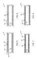
FIG. 2 illustrates another vaso-occlusive device 10. The vaso-occlusive device 10 includes afirst coil 12a and asecond coil 12b. The first andsecond coils first coil 12a is between two adjacent loops from thesecond coil 12b. In the illustrated device, the vaso-occlusive 10 may be formed by co-winding two elongated members (e.g., two wires). - In the illustrated device, the
first coil 12a and thesecond coil 12b may be made from different materials. For example, in some devices, thefirst coil 12a may be made from a metal, such as pure platinum, and thesecond coil 12b may be made from an alloy, such as platinum-tungsten alloy, e.g., 8% tungsten and the remainder platinum. The mechanical strength of pure platinum is about 1/3 of the platinum-tungsten alloy. Thus, forming part of thedevice 10 using a softer wire may provide a softer vaso-occlusive device 10 (e.g., for a given cross sectional dimension of the elongated member forming thecoil 12a/12b). It should be noted that thefirst coil 12a is not limited to being formed from a metal, and that in other embodiments, thefirst coil 12a may be made from an alloy or a non-metallic material. Also, in other devices, thesecond coil 12b may not be an alloy, and may be made from a metal or a non-metallic material. - As shown in
FIG. 3 , in other embodiments, thefirst coil 12a may be made from a wire having acore 30 and anouter layer 32, and thesecond coil 12b may be made from a metal (e.g., platinum), alloy (e.g., platinum-tungsten alloy), or a non-metallic material. In such embodiments, the core of the wire making up thefirst coil 12a may be made from metal, such as platinum, and the outer layer may be made from an alloy, such as platinum-tungsten alloy, e.g., 8% tungsten and the remainder platinum. The mechanical strength of pure platinum is about 1/3 of the platinum-tungsten alloy. Thus, thesofter platinum core 30 may provide asofter coil 12a (e.g., for a given cross sectional dimension of the elongated member forming thecoil 12a). This in turn provides a softer vaso-occlusive device 10. - In the embodiments, the core and the outer layer are made from different materials. For example, the materials for the core and the outer layer described previously may be switched. In the illustrated embodiments, the
wires respective coils wires respective coils occlusive device 10. - In any of the embodiments described herein, the vaso-
occlusive device 10 may have coil with different degrees of pitch along the length of thecoil 12. For example, as shown inFIG. 4 , the vaso-occlusive device 10 may have a closed pitch at adistal section 50, an open pitch at anintermediate section 52, and a more open pitch at aproximal section 54. Such configuration provides a variable stiffness along the length of the vaso-occlusive device 10, wherein thedistal section 50 is stiffer than theproximal sections distal section 50 allows the vasoocclusive device to better anchor against the wall of an aneurysm. On the other hand, the softerproximal sections - In other embodiments, instead of having three sections with three different pitches, the vaso-
occlusive device 10 may have more than three sections with more than three different pitches, or may have less than three sections with less than three different pitches. In further embodiments, the variability of the pitch along the length of the vaso-occlusive device 10 may be gradual. -
FIG. 5 illustrates another vaso-occlusive device 10. The vaso-occlusive device 10 includes afirst coil 12a and asecond coil 12b. Thefirst coil 12a has a plurality of loops that define a lumen therethrough, and thesecond coil 12b is located within the lumen of thefirst coil 12a. In the illustrated devices, thefirst coil 12a and thesecond coil 12b are made from the same material. For example, the first andsecond coils coils coils wires respective coils wires respective coils - It should be noted that the vaso-
occlusive device 10 ofFIG. 5 is advantageous because forming the vaso-occlusive device 10 using twocoils occlusive device 10. In particular, the vaso-occlusive device 10 formed by the twocoils thickness 80 will be more flexible compared to a vaso-occlusive device formed from a single wire having across-sectional dimension 80, and with a same material as that of thecoils thickness 80 of a wall of the vaso-occlusive device 10, and a given material, formed the vaso-occlusive device 10 using twocoils cross-sectional dimension 80 will provide a cross-sectional property (e.g., moment of inertia, or bending stiffness) that is higher than the cross-sectional property of the combined twowires occlusive device 10 undergoes bending, part(s) of thecoil 12b along the length of thecoil 12b will be allowed to move (e.g., slide longitudinally) relative to thecoil 12a, thereby allowing the vaso-occlusive device 10 to more easily bend. -
FIG. 6 illustrates a variation of the vaso-occlusive device 10 ofFIG. 5 . In particular, the vaso-occlusive device is the same as that shown inFIG. 5 , except that theouter coil 12a has loops that are more spaced apart than that of theinner coil 12b. As shown in the illustrated devices, theinner coil 12b has a closed pitch, and theouter coil 12a has an open pitch. Such configuration may provide further softness for the vaso-occlusive device 10. In other devices, theinner coil 12b may also have an open pitch. In such devices, theouter coil 12a may have an open pitch that is more open that that of theinner coil 12b. - In further devices, the
inner coil 12b may have a pitch that is more open that that of theouter coil 12a. For example, in other devices, theouter coil 12a may have a closed pitch, and theinner coil 12b may have an open pitch. Such configuration provides a vaso-occlusive device 10 that has a substantially continuous outer surface formed by the loops of theouter coil 12a. - In other devices, the first and
second coils devices 10 ofFIGS. 5 and 6 may be made from different materials. For example, as shown inFIG. 7 , in other devices, theouter coil 12a may be made from a metal, such as pure platinum, and theinner coil 12b may be made from an alloy, such as platinum-tungsten alloy, e.g., 8% tungsten and the remainder platinum. In other devices, theouter coil 12a may be made from an alloy, or a non-metallic material. Also, in other devices, theinner coil 12b may be made from a metal or a non-metallic material. By selecting different materials for constructing thecoils occlusive device 10. -
FIG. 8 illustrates a variation of the vaso-occlusive device 10 ofFIG. 7 . In particular, the vaso-occlusive device 10 is the same as that shown inFIG. 7 , except that theouter coil 12a has loops that are more spaced apart than that of theinner coil 12b. As shown in the illustrated devices, theinner coil 12b has a closed pitch, and theouter coil 12a has an open pitch. Such configuration may provide further softness for the vaso-occlusive device 10. In other devices, theinner coil 12b may also have an open pitch. In such devices, theouter coil 12a may have an open pitch that is more open that that of theinner coil 12b. - In further devices, the
inner coil 12b may have a pitch that is more open that that of theouter coil 12a. For example, in other devices, theouter coil 12a may have a closed pitch, and theinner coil 12b may have an open pitch. Such configuration provides a vaso-occlusive device 10 that has a substantially continuous outer surface formed by the loops of theouter coil 12a. - Regarding the above-described devices of
FIGS. 5-8 , in embodiments the wire used for the outer coil may alternatively be made from a pure platinum or platinum-tungsten alloy, and the wire for the inner coil may alternatively be made of a material consisting of a platinum core with an outer layer of platinum-tungsten alloy, or from a material consisting of a core of platinum-tungsten alloy and an outer layer of platinum. More alternatively, the wire for the outer coil can be made from a material consisting of a platinum core and an outer layer of platinum-tungsten alloy, or from a material consisting of a platinum-tungsten core and an outer layer of pure platinum, while the wire for inner coil can be made from pure platinum or platinum-tungsten alloy. Furthermore, the respective outer and inner coils of devices not being according to the invention can alternatively be made of a polymer, a ceramic, a bioactive material, or a combination of such materials. For example, a bioactive coating may be applied to one or both of the outer and inner metallic, polymeric and/or ceramic coils. - Furthermore, while the above-described embodiments of
FIGS. 5-8 are directed to double-coil embodiments, i.e., having an outer coil layer and an inner coil layer, one or more additional coil layers may be included in alternative embodiments for a total of three or more coil layers, in accordance with the inventive embodiments described herein. Such three-or-more coil layer embodiments would comprise an outer coil layer, and two or more inner coil layers. -
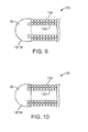
FIG. 9 illustrates an end (e.g., adistal end 16 or a proximal end 18) of the vaso-occlusive device 10 in accordance with some embodiments. The vaso-occlusive device 10 may be any of the vaso-occlusive devices 10 described with reference toFIGS. 5-8 . As shown in the illustrated embodiments, the end of theinner coil 12b is fixedly attached to ablunt tip 90. In particular, the end of theinner coil 12b is embedded within theblunt tip 90. In other embodiments, the attachment of thecoil 12b to theblunt tip 90 may be accomplished using a weld, glue, screw threads, or other suitable adhesive. In the illustrated embodiments, theouter coil 12a is coupled to theinner coil 12b by friction, and is not directly attached to theblunt tip 90. In other embodiments, theouter coil 12a may be directly secured to theinner coil 12b using a weld, glue, or a suitable adhesive. For example, theouter coil 12a may be welded to theinner coil 12b at one or both ends of thecoil 12a. In further embodiments, in addition to, or instead of, securing to theinner coil 12b, theouter coil 12a may be directly attached to the blunt tip 90 (FIG. 10 ). - For example, the
outer coil 12a may be embedded within theblunt tip 90 as that shown in the figure, or be directly attached to theblunt tip 90 using other mechanisms, such as a weld, glue, screw threads, or other suitable adhesive. In some embodiments, theinner coil 12b is secured to respective blunt tips at opposite ends of theinner coil 12b. Theouter coil 12a may be secured to a blunt tip at one of the ends of thecoil 12a, or to the respective blunt tips at both ends of thecoil 12a. Securing theouter coil 12a to only one of the blunt tips (or to only one end of theinner coil 12b) has the advantage in that theouter coil 12a will be allowed to move more easily relative to theinner coil 12b, thereby providing a vaso-occlusive device 10 that is softer. - It should be noted that the materials for forming the coil(s) 12 of the vaso-
occlusive device 10 should not be limited to the examples described previously. In any of the devices described herein, the material for the coil(s) 12 may be a radio-opaque material such as a metal or a polymer. The material for the coil(s) 12 may be rhodium, palladium, rhenium, as well as tungsten, gold, silver, tantalum, and alloys of these metals. These metals have significant radio-opacity and in their alloys may be tailored to accomplish an appropriate blend of flexibility and stiffness. They are also largely biologically inert. Also, any materials which maintain their shape despite being subjected to high stress may be used to construct the coil(s) 12. - For example, certain "super-elastic alloys" include various nickel/titanium alloys (48-58 atomic % nickel and optionally containing modest amounts of iron); copper/zinc alloys (38-42 weight % zinc); copper/zinc alloys containing 1-10 weight % of beryllium, silicon, tin, aluminum, or gallium; or nickel/aluminum alloys (36-38 atomic % aluminum), may be used. In further embodiments, titanium-nickel alloy known as "nitinol" may be used to form the coil(s) 12. These are very sturdy alloys which will tolerate significant flexing without deformation even when used as very small diameter wire.
- In any of the embodiments described herein, the
wire 14 used to form the coil may have a cross-sectional dimension that is in the range of 0,0005 mm and 0,15 mm (0.00002 and 0.006 inches). Thecoil 12 formed by thewire 14 may have a cross-sectional dimension between 0,076 mm and 0,64 mm (0.003 and 0.025 inches). For neurovascular applications, thecoil 12 diameter may be anywhere from 0,2 mm to 0,46 mm (0.008 to 0.018 inches). In other embodiments, thewire 14 may have other cross-sectional dimensions, and thecoil 12 may have other cross-sectional dimensions. In some embodiments, thewire 14 for forming the coil should have a sufficient diameter to provide a hoop strength to the resultingdevice 10 sufficient to hold thedevice 10 in place within the chosen body site, lumen or cavity, without substantially distending the wall of the site and without moving from the site as a result of the repetitive fluid pulsing found in the vascular system. - In any of the embodiments described herein, the axial length of the
coil 12 may be in the range of 0.5 to 100 cm, and more preferably, in the range of 2.0 to 40 cm. Depending upon use, thecoil 12 may have 10-75 turns per centimeter, or more preferably 10-40 turns per centimeter. In other embodiments, thecoil 12 may have other lengths and/or other number of turns per centimeter. - In some embodiments, the vaso-
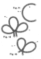
occlusive devices 10 described herein may have the simple linear shape shown previously, or may have shapes which are more complex.FIGS. 11, 12, and 13 show what are termed "secondary" shapes in that they are formed from the primary coil by winding the primary coil on a form of a desired shape and then heat treating the soformed shape.FIG. 11 shows a vaso-occlusive device 10 having a "C" shape.FIG. 12 shows a vaso-occlusive device 10 having a clover-leaf shape.FIG. 13 shows a vaso-occlusive device 10 having a double-loop configuration. These are examples of the various secondary shapes that may be implemented in embodiments of the vaso-occlusive device 10 described herein. - In any of the embodiments described herein, the vaso-
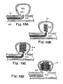
occlusive device 10 may be delivered using a catheter.FIG. 14 shows acatheter 200 containing the vaso-occlusive device 10 as described herein. Thecatheter 200 may have a distal radio-opaque marker 206 if so desired, so that a user may determine the positioning of the distal end of thecatheter 200 within a body during use. Proximally of the vaso-occlusive device 10 is aconnective wire 208 which is insulated at all points proximal of anelectrolytic joint 210. Thewire 208 may insulated with a combination of polytetrafluoroethylene and PARYLENE (polyparaxyxylene), except for the small sacrificial joint 210 which is intended to be the site of the electrolysis as the joint 210 is eroded or severed and the vaso-occlusive device 10 deployed into the body site. - In some embodiments, the distal portion of the
catheter 200 may be made from any material, such as polyurethane, polyvinylchloride, silicones, or other polymers. Theconnective wire 208 used therein should be very flexible so that it does not interfere with the movement of thecatheter 200. It is conductive and insulated proximally of theelectrolytic joint 210. Introduction of an electric current into theconnective wire 208 will cause the electrolytic joint 210 to erode and the vaso-occlusive device 10 to become detached. In the illustrated embodiments, the vaso-occlusive device 10 further includes a stretch-resistingmember 204 for preventing over-stretching of the vaso-occlusive device 10. In other embodiments, the stretch-resistingmember 204 is not needed. - It should be noted that the manner of releasing the vaso-
occlusive device 10 from a delivery catheter is not limited to the example described, and that other ways of discharging vaso-occlusive devices into the human vasculature are possible. For example, in other embodiments, mechanically detachable devices may be used to detachably couple the vaso-occlusive device 10 to the pusher. - In some embodiments, the vaso-
occlusive device 10 may be unscrewed from a pusher having interlocking surfaces. In other embodiments, interlocking clasps mounted both on the pusher and on the vaso-occlusive device 10 may be used to detachably couple the vaso-occlusive device 10 to the pusher. In other embodiments, an interlocking ball and keyway-type coupling may be used to detachably couple the vaso-occlusive device 10 from the pusher. In further embodiments, a pusher-vaso-occlusive coil assembly may have a proximally extending wire carrying a ball on its proximal end and a pusher having a similar end. The two ends are interlocked and disengage when expelled from the distal tip of the catheter. -
FIGS. 15A-15D depict a deployment method for introduction of any of the embodiments of the vaso-occlusive device 10 described here. Specifically,FIG. 15A shows the distal tip of adelivery catheter 310, which is within theopening 312 of ananeurysm 314 found in anartery 316. The distal or end section of the vaso-occlusive device 10 is shown within thecatheter 310. The vaso-occlusive device 10 may be any of the vaso-occlusive devices described herein. The advancement of the vaso-occlusive device 10 relative to thecatheter 310 may be achieved using a plunger/pusher that pushes the vaso-occlusive device 10 distally relative to thecatheter 310. - In some embodiments, the vaso-
occlusive device 10 may have a secondary shape. In such embodiments, while the vaso-occlusive device 10 is housed within thecatheter 310, the vaso-occlusive device 10 is stretched into a low profile. When the vaso-occlusive device 10 is deployed out of the lumen of thecatheter 310, the vaso-occlusive device 10 then assumes its relaxed configuration to have the secondary shape. - In
FIG. 15B , the distal end portion of the vaso-occlusive device 10 has exited the distal end of thecatheter 310 and has wound into a secondary shape within theaneurysm 314.FIG. 15C shows the completion of the formation of the secondary shape within theaneurysm 314. - In some embodiments, the pusher merely abuts against the vaso-
occlusive device 10. In such embodiments, as soon as the vaso-occlusive device 10 is deployed out of the lumen of thecatheter 310, the vaso-occlusive device 10 is then separated from the pusher. In other embodiments, the vaso-occlusive device 10 may be mechanically coupled to the pusher. In such embodiments, the user may operate on the coupling mechanism to detach the vaso-occlusive device 10 from the pusher. For example, if the coupling mechanism includes an electrolytic joint, the user may apply energy to sever the joint, thereby releasing the vaso-occlusive device 10 from the pusher. -
FIG. 15D shows the separation of the vaso-occlusive device 10 from the pusher, placement within theaneurysm 314, and the withdrawal of the catheter from the mouth of the aneurysm. - In any of the embodiments described herein, the vaso-occlusive device may further include fibrous elements coupled to the coil. For example, the fibrous elements may extend in a sinusoidal fashion down the length of the coil, and may be coupled to loops of the coil. The fibrous elements may enhance the ability of the coil to fill space within the vasculature and to facilitate formation of embolus and subsequent allied tissue. The fibrous materials may be made from biocompatible materials, such as Dacron (polyester), polyglycolic acid, polylactic acid, fluoropolymers (polytetrafluoroethylene), Nylon (polyamide), or silk. The strands forming the braid should be reasonably heavy, e.g., having tensile strength of greater than about 0,67 N (0.15 pounds). The materials mentioned, to the extent that they are thermoplastics, may be melted or fused to the coils. Alternatively, they may be glued or otherwise fastened to the coils. Preferred materials include Dacron.
- Also, in any of the embodiments described herein, the vaso-
occlusive device 10 may further include a stretch-resisting member coupled (e.g., soldered, brazed, glued, or otherwise fixedly attached) to both ends of the vaso-occlusive device 10 and extending through a central lumen of the vaso-occlusive device 10. The stretch-resisting member enhances the tensile strength of the vaso-occlusive device 10, and may prevent the vaso-occlusive device 10 from being over-stretched during use. In other embodiments, the stretch-resisting member may be coupled to the vaso-occlusive device 10 at one or more locations intermediate to the ends of the vaso-occlusive device 10. The stretch-resisting member may be thermoplastic or thermosetting and comprise a bundle of threads or a single filament melted onto, glued, or otherwise fixedly attached to the vaso-occlusive device 10. In some instances, it may also be desirable to include one or more metallic strands in the stretch-resisting member to provide stiffness or electrical conductance for specific applications.
Claims (5)
- A vaso-occlusive device (10), comprising:a coil (12) having a proximal end (18) and a distal end (16), the coil (12) comprising a helically wound elongated member (14) having a core (30) and an outer layer (32),characterized in that the outer layer (32) being made from a metal or alloy, and has a stiffness that is different from a stiffness of the core (30).
- The vaso-occlusive device (10) of claim 1, wherein the core (30) is made from a first material, and the outer layer (32) is made from a second material stiffer than the first material.
- The vaso-occlusive device (10) of claim 1, wherein the core (30) is made from a first material, and the outer layer (32) is made from a second material softer than the first material.
- The vaso-occlusive device (10) of claim 1, wherein the core (30) comprises platinum, and wherein the outer layer (32) comprises a platinum-tungsten alloy.
- The vaso-occlusive device (10) of any of claims 1-4, wherein the coil (12) has a distal portion (50) and a proximal portion (54), and a pitch of the coil (12) at the distal portion (50) is less open than a pitch of the coil (12) at the proximal portion (54).
Priority Applications (1)
| Application Number | Priority Date | Filing Date | Title |
|---|---|---|---|
| EP14174949.9A EP2813189A1 (en) | 2010-04-05 | 2011-04-01 | Vaso-occlusive devices |
Applications Claiming Priority (2)
| Application Number | Priority Date | Filing Date | Title |
|---|---|---|---|
| US32105210P | 2010-04-05 | 2010-04-05 | |
| PCT/US2011/030972 WO2011126946A1 (en) | 2010-04-05 | 2011-04-01 | Vaso-occlusive devices |
Related Child Applications (1)
| Application Number | Title | Priority Date | Filing Date |
|---|---|---|---|
| EP14174949.9A Division EP2813189A1 (en) | 2010-04-05 | 2011-04-01 | Vaso-occlusive devices |
Publications (2)
| Publication Number | Publication Date |
|---|---|
| EP2555690A1 EP2555690A1 (en) | 2013-02-13 |
| EP2555690B1 true EP2555690B1 (en) | 2014-07-02 |
Family
ID=44315028
Family Applications (2)
| Application Number | Title | Priority Date | Filing Date |
|---|---|---|---|
| EP14174949.9A Withdrawn EP2813189A1 (en) | 2010-04-05 | 2011-04-01 | Vaso-occlusive devices |
| EP11713641.6A Active EP2555690B1 (en) | 2010-04-05 | 2011-04-01 | Vaso-occlusive devices |
Family Applications Before (1)
| Application Number | Title | Priority Date | Filing Date |
|---|---|---|---|
| EP14174949.9A Withdrawn EP2813189A1 (en) | 2010-04-05 | 2011-04-01 | Vaso-occlusive devices |
Country Status (3)
| Country | Link |
|---|---|
| US (1) | US20110245861A1 (en) |
| EP (2) | EP2813189A1 (en) |
| WO (1) | WO2011126946A1 (en) |
Families Citing this family (19)
| Publication number | Priority date | Publication date | Assignee | Title |
|---|---|---|---|---|
| EP1793744B1 (en) | 2004-09-22 | 2008-12-17 | Dendron GmbH | Medical implant |
| WO2012161953A2 (en) * | 2011-05-23 | 2012-11-29 | Stryker Corporation | Vaso-occlusive devices with in-situ stiffening |
| US9011480B2 (en) | 2012-01-20 | 2015-04-21 | Covidien Lp | Aneurysm treatment coils |
| US9687245B2 (en) | 2012-03-23 | 2017-06-27 | Covidien Lp | Occlusive devices and methods of use |
| EP2674114A1 (en) * | 2012-06-11 | 2013-12-18 | Acandis GmbH & Co. KG | Implant for occlusion of vascular anomalies and method for producing such an implant |
| EP3086718A1 (en) * | 2013-12-26 | 2016-11-02 | Stryker Corporation | Vaso-occlusive coil with bending sections |
| CN108186074A (en) | 2014-02-27 | 2018-06-22 | 因库麦迪斯有限公司 | For treating the framework microcoils of vascular diseases |
| US9629635B2 (en) * | 2014-04-14 | 2017-04-25 | Sequent Medical, Inc. | Devices for therapeutic vascular procedures |
| US9713475B2 (en) | 2014-04-18 | 2017-07-25 | Covidien Lp | Embolic medical devices |
| RU2017105842A (en) | 2014-07-25 | 2018-08-27 | Инкьюмедкс, Инк. | COATED EMBOLIC SPIRALS |
| US20160213380A1 (en) | 2015-01-22 | 2016-07-28 | Boston Scientific Scimed, Inc. | Occlusion device having spherical secondary shape and mandrel for forming same |
| US10869673B2 (en) | 2015-02-05 | 2020-12-22 | Boston Scientific Scimed, Inc. | Embolic coil with kick-in tail |
| US10675030B2 (en) * | 2017-08-04 | 2020-06-09 | C.R. Bard, Inc. | Absorbable surgical coil fastener |
| CN109745094B (en) * | 2018-12-29 | 2021-09-03 | 先健科技(深圳)有限公司 | Plugging device |
| US11612678B2 (en) * | 2019-09-11 | 2023-03-28 | Stryker Corporation | Intravascular devices |
| CN116370007A (en) * | 2019-12-24 | 2023-07-04 | 上海微创心脉医疗科技(集团)股份有限公司 | A kind of occluder and system |
| CN112656476B (en) * | 2020-12-31 | 2025-12-30 | 神遁医疗科技(上海)有限公司 | An embolic agent and its preparation method |
| CN112641484B (en) * | 2020-12-31 | 2025-04-15 | 神遁医疗科技(上海)有限公司 | Embolic material and preparation method thereof |
| US20240016497A1 (en) * | 2022-07-12 | 2024-01-18 | Medtronic Inc. | Implantable embolization device |
Family Cites Families (13)
| Publication number | Priority date | Publication date | Assignee | Title |
|---|---|---|---|---|
| US5690666A (en) * | 1992-11-18 | 1997-11-25 | Target Therapeutics, Inc. | Ultrasoft embolism coils and process for using them |
| US5514176A (en) * | 1995-01-20 | 1996-05-07 | Vance Products Inc. | Pull apart coil stent |
| US5749894A (en) * | 1996-01-18 | 1998-05-12 | Target Therapeutics, Inc. | Aneurysm closure method |
| US5649949A (en) * | 1996-03-14 | 1997-07-22 | Target Therapeutics, Inc. | Variable cross-section conical vasoocclusive coils |
| US5690667A (en) * | 1996-09-26 | 1997-11-25 | Target Therapeutics | Vasoocclusion coil having a polymer tip |
| US6187024B1 (en) * | 1998-11-10 | 2001-02-13 | Target Therapeutics, Inc. | Bioactive coating for vaso-occlusive devices |
| US20030028209A1 (en) * | 2001-07-31 | 2003-02-06 | Clifford Teoh | Expandable body cavity liner device |
| US7182735B2 (en) * | 2003-02-26 | 2007-02-27 | Scimed Life Systems, Inc. | Elongated intracorporal medical device |
| US7309345B2 (en) * | 2003-07-25 | 2007-12-18 | Boston Scientific-Scimed, Inc. | Method and system for delivering an implant utilizing a lumen reducing member |
| US20070239199A1 (en) * | 2006-03-31 | 2007-10-11 | Swaminathan Jayaraman | Inferior vena cava filter |
| US7901704B2 (en) * | 2007-08-21 | 2011-03-08 | Boston Scientific Scimed, Inc. | Embolization |
| US8702746B2 (en) * | 2008-04-29 | 2014-04-22 | Cook Medical Technologies Llc | Device and method for occlusion of fluid flow through a body vessel |
| US20110184454A1 (en) * | 2010-01-27 | 2011-07-28 | Penumbra, Inc. | Embolic implants |
-
2011
- 2011-04-01 EP EP14174949.9A patent/EP2813189A1/en not_active Withdrawn
- 2011-04-01 WO PCT/US2011/030972 patent/WO2011126946A1/en not_active Ceased
- 2011-04-01 US US13/078,745 patent/US20110245861A1/en not_active Abandoned
- 2011-04-01 EP EP11713641.6A patent/EP2555690B1/en active Active
Also Published As
| Publication number | Publication date |
|---|---|
| EP2813189A1 (en) | 2014-12-17 |
| WO2011126946A9 (en) | 2012-07-19 |
| WO2011126946A1 (en) | 2011-10-13 |
| US20110245861A1 (en) | 2011-10-06 |
| EP2555690A1 (en) | 2013-02-13 |
Similar Documents
| Publication | Publication Date | Title |
|---|---|---|
| EP2555690B1 (en) | Vaso-occlusive devices | |
| CA2198765C (en) | Stretch resistant vaso-occlusive coils | |
| US6013084A (en) | Stretch resistant vaso-occlusive coils (II) | |
| US5833705A (en) | Stretch resistant vaso-occlusive coils | |
| US5582619A (en) | Stretch resistant vaso-occlusive coils | |
| EP0964648B1 (en) | Vaso-occlusive coil with conical ends | |
| EP1845866B1 (en) | Vaso-occlusive device having pivotable coupling | |
| CA2178126C (en) | Three-dimensional in-filling vaso-occlusive coils | |
| US10542995B2 (en) | Vaso-occlusive device | |
| US20050192621A1 (en) | Polymer covered vaso-occlusive devices and methods of producing such devices | |
| EP2088936A2 (en) | Mechanically detachable vaso-occlusive device | |
| KR19980069297A (en) | Renal Vascular Occlusion Device | |
| AU687324B2 (en) | Stretch resistant vaso-occlusive coils |
Legal Events
| Date | Code | Title | Description |
|---|---|---|---|
| PUAI | Public reference made under article 153(3) epc to a published international application that has entered the european phase |
Free format text: ORIGINAL CODE: 0009012 |
|
| 17P | Request for examination filed |
Effective date: 20120914 |
|
| AK | Designated contracting states |
Kind code of ref document: A1 Designated state(s): AL AT BE BG CH CY CZ DE DK EE ES FI FR GB GR HR HU IE IS IT LI LT LU LV MC MK MT NL NO PL PT RO RS SE SI SK SM TR |
|
| DAX | Request for extension of the european patent (deleted) | ||
| GRAP | Despatch of communication of intention to grant a patent |
Free format text: ORIGINAL CODE: EPIDOSNIGR1 |
|
| INTG | Intention to grant announced |
Effective date: 20140113 |
|
| GRAS | Grant fee paid |
Free format text: ORIGINAL CODE: EPIDOSNIGR3 |
|
| GRAA | (expected) grant |
Free format text: ORIGINAL CODE: 0009210 |
|
| AK | Designated contracting states |
Kind code of ref document: B1 Designated state(s): AL AT BE BG CH CY CZ DE DK EE ES FI FR GB GR HR HU IE IS IT LI LT LU LV MC MK MT NL NO PL PT RO RS SE SI SK SM TR |
|
| REG | Reference to a national code |
Ref country code: GB Ref legal event code: FG4D |
|
| REG | Reference to a national code |
Ref country code: CH Ref legal event code: EP Ref country code: AT Ref legal event code: REF Ref document number: 675478 Country of ref document: AT Kind code of ref document: T Effective date: 20140715 |
|
| REG | Reference to a national code |
Ref country code: IE Ref legal event code: FG4D |
|
| REG | Reference to a national code |
Ref country code: DE Ref legal event code: R096 Ref document number: 602011008115 Country of ref document: DE Effective date: 20140814 |
|
| REG | Reference to a national code |
Ref country code: NL Ref legal event code: T3 |
|
| REG | Reference to a national code |
Ref country code: AT Ref legal event code: MK05 Ref document number: 675478 Country of ref document: AT Kind code of ref document: T Effective date: 20140702 |
|
| REG | Reference to a national code |
Ref country code: LT Ref legal event code: MG4D |
|
| PG25 | Lapsed in a contracting state [announced via postgrant information from national office to epo] |
Ref country code: NO Free format text: LAPSE BECAUSE OF FAILURE TO SUBMIT A TRANSLATION OF THE DESCRIPTION OR TO PAY THE FEE WITHIN THE PRESCRIBED TIME-LIMIT Effective date: 20141002 Ref country code: BG Free format text: LAPSE BECAUSE OF FAILURE TO SUBMIT A TRANSLATION OF THE DESCRIPTION OR TO PAY THE FEE WITHIN THE PRESCRIBED TIME-LIMIT Effective date: 20141002 Ref country code: SE Free format text: LAPSE BECAUSE OF FAILURE TO SUBMIT A TRANSLATION OF THE DESCRIPTION OR TO PAY THE FEE WITHIN THE PRESCRIBED TIME-LIMIT Effective date: 20140702 Ref country code: FI Free format text: LAPSE BECAUSE OF FAILURE TO SUBMIT A TRANSLATION OF THE DESCRIPTION OR TO PAY THE FEE WITHIN THE PRESCRIBED TIME-LIMIT Effective date: 20140702 Ref country code: CZ Free format text: LAPSE BECAUSE OF FAILURE TO SUBMIT A TRANSLATION OF THE DESCRIPTION OR TO PAY THE FEE WITHIN THE PRESCRIBED TIME-LIMIT Effective date: 20140702 Ref country code: LT Free format text: LAPSE BECAUSE OF FAILURE TO SUBMIT A TRANSLATION OF THE DESCRIPTION OR TO PAY THE FEE WITHIN THE PRESCRIBED TIME-LIMIT Effective date: 20140702 Ref country code: PT Free format text: LAPSE BECAUSE OF FAILURE TO SUBMIT A TRANSLATION OF THE DESCRIPTION OR TO PAY THE FEE WITHIN THE PRESCRIBED TIME-LIMIT Effective date: 20141103 Ref country code: GR Free format text: LAPSE BECAUSE OF FAILURE TO SUBMIT A TRANSLATION OF THE DESCRIPTION OR TO PAY THE FEE WITHIN THE PRESCRIBED TIME-LIMIT Effective date: 20141003 Ref country code: ES Free format text: LAPSE BECAUSE OF FAILURE TO SUBMIT A TRANSLATION OF THE DESCRIPTION OR TO PAY THE FEE WITHIN THE PRESCRIBED TIME-LIMIT Effective date: 20140702 |
|
| PG25 | Lapsed in a contracting state [announced via postgrant information from national office to epo] |
Ref country code: HR Free format text: LAPSE BECAUSE OF FAILURE TO SUBMIT A TRANSLATION OF THE DESCRIPTION OR TO PAY THE FEE WITHIN THE PRESCRIBED TIME-LIMIT Effective date: 20140702 Ref country code: RS Free format text: LAPSE BECAUSE OF FAILURE TO SUBMIT A TRANSLATION OF THE DESCRIPTION OR TO PAY THE FEE WITHIN THE PRESCRIBED TIME-LIMIT Effective date: 20140702 Ref country code: IS Free format text: LAPSE BECAUSE OF FAILURE TO SUBMIT A TRANSLATION OF THE DESCRIPTION OR TO PAY THE FEE WITHIN THE PRESCRIBED TIME-LIMIT Effective date: 20141102 Ref country code: AT Free format text: LAPSE BECAUSE OF FAILURE TO SUBMIT A TRANSLATION OF THE DESCRIPTION OR TO PAY THE FEE WITHIN THE PRESCRIBED TIME-LIMIT Effective date: 20140702 Ref country code: PL Free format text: LAPSE BECAUSE OF FAILURE TO SUBMIT A TRANSLATION OF THE DESCRIPTION OR TO PAY THE FEE WITHIN THE PRESCRIBED TIME-LIMIT Effective date: 20140702 Ref country code: CY Free format text: LAPSE BECAUSE OF FAILURE TO SUBMIT A TRANSLATION OF THE DESCRIPTION OR TO PAY THE FEE WITHIN THE PRESCRIBED TIME-LIMIT Effective date: 20140702 Ref country code: LV Free format text: LAPSE BECAUSE OF FAILURE TO SUBMIT A TRANSLATION OF THE DESCRIPTION OR TO PAY THE FEE WITHIN THE PRESCRIBED TIME-LIMIT Effective date: 20140702 |
|
| REG | Reference to a national code |
Ref country code: DE Ref legal event code: R097 Ref document number: 602011008115 Country of ref document: DE |
|
| PG25 | Lapsed in a contracting state [announced via postgrant information from national office to epo] |
Ref country code: RO Free format text: LAPSE BECAUSE OF FAILURE TO SUBMIT A TRANSLATION OF THE DESCRIPTION OR TO PAY THE FEE WITHIN THE PRESCRIBED TIME-LIMIT Effective date: 20140702 Ref country code: IT Free format text: LAPSE BECAUSE OF FAILURE TO SUBMIT A TRANSLATION OF THE DESCRIPTION OR TO PAY THE FEE WITHIN THE PRESCRIBED TIME-LIMIT Effective date: 20140702 Ref country code: SK Free format text: LAPSE BECAUSE OF FAILURE TO SUBMIT A TRANSLATION OF THE DESCRIPTION OR TO PAY THE FEE WITHIN THE PRESCRIBED TIME-LIMIT Effective date: 20140702 Ref country code: EE Free format text: LAPSE BECAUSE OF FAILURE TO SUBMIT A TRANSLATION OF THE DESCRIPTION OR TO PAY THE FEE WITHIN THE PRESCRIBED TIME-LIMIT Effective date: 20140702 Ref country code: DK Free format text: LAPSE BECAUSE OF FAILURE TO SUBMIT A TRANSLATION OF THE DESCRIPTION OR TO PAY THE FEE WITHIN THE PRESCRIBED TIME-LIMIT Effective date: 20140702 |
|
| PLBE | No opposition filed within time limit |
Free format text: ORIGINAL CODE: 0009261 |
|
| STAA | Information on the status of an ep patent application or granted ep patent |
Free format text: STATUS: NO OPPOSITION FILED WITHIN TIME LIMIT |
|
| 26N | No opposition filed |
Effective date: 20150407 |
|
| PG25 | Lapsed in a contracting state [announced via postgrant information from national office to epo] |
Ref country code: LU Free format text: LAPSE BECAUSE OF FAILURE TO SUBMIT A TRANSLATION OF THE DESCRIPTION OR TO PAY THE FEE WITHIN THE PRESCRIBED TIME-LIMIT Effective date: 20150401 Ref country code: SI Free format text: LAPSE BECAUSE OF FAILURE TO SUBMIT A TRANSLATION OF THE DESCRIPTION OR TO PAY THE FEE WITHIN THE PRESCRIBED TIME-LIMIT Effective date: 20140702 Ref country code: MC Free format text: LAPSE BECAUSE OF FAILURE TO SUBMIT A TRANSLATION OF THE DESCRIPTION OR TO PAY THE FEE WITHIN THE PRESCRIBED TIME-LIMIT Effective date: 20140702 |
|
| REG | Reference to a national code |
Ref country code: CH Ref legal event code: PL |
|
| GBPC | Gb: european patent ceased through non-payment of renewal fee |
Effective date: 20150401 |
|
| REG | Reference to a national code |
Ref country code: NL Ref legal event code: MM Effective date: 20150501 |
|
| PG25 | Lapsed in a contracting state [announced via postgrant information from national office to epo] |
Ref country code: GB Free format text: LAPSE BECAUSE OF NON-PAYMENT OF DUE FEES Effective date: 20150401 Ref country code: LI Free format text: LAPSE BECAUSE OF NON-PAYMENT OF DUE FEES Effective date: 20150430 Ref country code: CH Free format text: LAPSE BECAUSE OF NON-PAYMENT OF DUE FEES Effective date: 20150430 |
|
| REG | Reference to a national code |
Ref country code: FR Ref legal event code: ST Effective date: 20151231 |
|
| PG25 | Lapsed in a contracting state [announced via postgrant information from national office to epo] |
Ref country code: FR Free format text: LAPSE BECAUSE OF NON-PAYMENT OF DUE FEES Effective date: 20150430 |
|
| PG25 | Lapsed in a contracting state [announced via postgrant information from national office to epo] |
Ref country code: NL Free format text: LAPSE BECAUSE OF NON-PAYMENT OF DUE FEES Effective date: 20150501 |
|
| PG25 | Lapsed in a contracting state [announced via postgrant information from national office to epo] |
Ref country code: BE Free format text: LAPSE BECAUSE OF FAILURE TO SUBMIT A TRANSLATION OF THE DESCRIPTION OR TO PAY THE FEE WITHIN THE PRESCRIBED TIME-LIMIT Effective date: 20140702 |
|
| PG25 | Lapsed in a contracting state [announced via postgrant information from national office to epo] |
Ref country code: MT Free format text: LAPSE BECAUSE OF FAILURE TO SUBMIT A TRANSLATION OF THE DESCRIPTION OR TO PAY THE FEE WITHIN THE PRESCRIBED TIME-LIMIT Effective date: 20140702 |
|
| PG25 | Lapsed in a contracting state [announced via postgrant information from national office to epo] |
Ref country code: HU Free format text: LAPSE BECAUSE OF FAILURE TO SUBMIT A TRANSLATION OF THE DESCRIPTION OR TO PAY THE FEE WITHIN THE PRESCRIBED TIME-LIMIT; INVALID AB INITIO Effective date: 20110401 Ref country code: SM Free format text: LAPSE BECAUSE OF FAILURE TO SUBMIT A TRANSLATION OF THE DESCRIPTION OR TO PAY THE FEE WITHIN THE PRESCRIBED TIME-LIMIT Effective date: 20140702 |
|
| PG25 | Lapsed in a contracting state [announced via postgrant information from national office to epo] |
Ref country code: TR Free format text: LAPSE BECAUSE OF FAILURE TO SUBMIT A TRANSLATION OF THE DESCRIPTION OR TO PAY THE FEE WITHIN THE PRESCRIBED TIME-LIMIT Effective date: 20140702 |
|
| PG25 | Lapsed in a contracting state [announced via postgrant information from national office to epo] |
Ref country code: MK Free format text: LAPSE BECAUSE OF FAILURE TO SUBMIT A TRANSLATION OF THE DESCRIPTION OR TO PAY THE FEE WITHIN THE PRESCRIBED TIME-LIMIT Effective date: 20140702 |
|
| PG25 | Lapsed in a contracting state [announced via postgrant information from national office to epo] |
Ref country code: AL Free format text: LAPSE BECAUSE OF FAILURE TO SUBMIT A TRANSLATION OF THE DESCRIPTION OR TO PAY THE FEE WITHIN THE PRESCRIBED TIME-LIMIT Effective date: 20140702 |
|
| P01 | Opt-out of the competence of the unified patent court (upc) registered |
Effective date: 20230523 |
|
| PGFP | Annual fee paid to national office [announced via postgrant information from national office to epo] |
Ref country code: IE Payment date: 20250321 Year of fee payment: 15 |
|
| PGFP | Annual fee paid to national office [announced via postgrant information from national office to epo] |
Ref country code: DE Payment date: 20250319 Year of fee payment: 15 |