EP2555560A1 - Base station, communication system and communication method - Google Patents

Base station, communication system and communication method Download PDF

Info

Publication number
EP2555560A1
EP2555560A1 EP11762407A EP11762407A EP2555560A1 EP 2555560 A1 EP2555560 A1 EP 2555560A1 EP 11762407 A EP11762407 A EP 11762407A EP 11762407 A EP11762407 A EP 11762407A EP 2555560 A1 EP2555560 A1 EP 2555560A1
Authority
EP
European Patent Office
Prior art keywords
base station
branch
calibration
coefficient
branches
Prior art date
Legal status (The legal status is an assumption and is not a legal conclusion. Google has not performed a legal analysis and makes no representation as to the accuracy of the status listed.)
Withdrawn
Application number
EP11762407A
Other languages
German (de)
French (fr)
Inventor
Hiroaki Takano
Current Assignee (The listed assignees may be inaccurate. Google has not performed a legal analysis and makes no representation or warranty as to the accuracy of the list.)
Sony Corp
Original Assignee
Sony Corp
Priority date (The priority date is an assumption and is not a legal conclusion. Google has not performed a legal analysis and makes no representation as to the accuracy of the date listed.)
Filing date
Publication date
Application filed by Sony Corp filed Critical Sony Corp
Publication of EP2555560A1 publication Critical patent/EP2555560A1/en
Withdrawn legal-status Critical Current

Links

Images

Classifications

    • HELECTRICITY
    • H04ELECTRIC COMMUNICATION TECHNIQUE
    • H04BTRANSMISSION
    • H04B7/00Radio transmission systems, i.e. using radiation field
    • H04B7/02Diversity systems; Multi-antenna system, i.e. transmission or reception using multiple antennas
    • H04B7/022Site diversity; Macro-diversity
    • H04B7/024Co-operative use of antennas of several sites, e.g. in co-ordinated multipoint or co-operative multiple-input multiple-output [MIMO] systems
    • HELECTRICITY
    • H04ELECTRIC COMMUNICATION TECHNIQUE
    • H04BTRANSMISSION
    • H04B17/00Monitoring; Testing
    • H04B17/20Monitoring; Testing of receivers
    • H04B17/21Monitoring; Testing of receivers for calibration; for correcting measurements
    • H04B17/22Monitoring; Testing of receivers for calibration; for correcting measurements for calibration of the receiver components

Definitions

  • the present invention relates to a base station, a communication system, and a communication method.
  • the relay technique refers to a technique by which a relay node relays communication between a base station (for example, a macro cell base station) and a communication terminal, and the relay technique is important in improving the throughput at a cell edge of a base station.
  • the carrier aggregation is a technique in which a use bandwidth is increased and a maximum throughput is improved by collectively treating a plurality of frequency bands each having a bandwidth of 20 MHz.
  • CoMP is a technique by which a plurality of base stations collaborate with each other to perform data communication with a communication terminal, and the coverage of high-data-rate communication can be increased.
  • CoMP refers to a technique by which a plurality of base stations simultaneously perform data communication with one communication terminal. According to this technique, since branches of a plurality of base stations can be used for data communication, an antenna gain and a signal to interference plus noise ratio (SINR) can be improved.
  • SINR signal to interference plus noise ratio
  • a base station has calculated a weight of a branch based on a channel matrix of an uplink from a communication terminal and then has obtained reception directivity.
  • transmission directivity matching reception directivity is considered to be obtained.
  • a transfer function of a transmission analog unit and a transfer function of a reception analog unit of each branch are different from each other, actual transmission directivity does not match reception directivity.
  • the calibration coefficient is a coefficient used to regularize a ratio of the transfer function of the transmission analog unit and the transfer function of the reception analog unit of each branch in one base station.
  • the branch calibration is disclosed in, for example, Patent Literature 1 and Patent Literature 2.
  • each base station individually performs branch calibration
  • each base station individually forms directivity and performs a CoMP, but efficient communication is expected to be difficult to perform.
  • MIMO communication 2 ⁇ N of 3 sets (N is the number of branches at a communication terminal side), but it is difficult to implement MIMO communication of 6 ⁇ N of a higher throughput.
  • the present invention is made in light of the above-mentioned problems, and it is an object of the present invention to provide a base station, a communication system, and a communication method, which are novel and improved, and which are capable of efficiently performing collaborative branch calibration through branches in a plurality of base stations.
  • a base station including a plurality of branches that perform CoMP transmission with another base station and a multiplying unit that multiplies a transmission signal from each of the plurality of branches by a calibration coefficient of each of the plurality of branches, wherein the calibration coefficient is a coefficient obtained by adjusting an individual calibration coefficient acquired by branch calibration between the plurality of branches in the base station based on a branch calibration result between a branch of the base station and a branch of the other base station.
  • the calibration coefficient of each of the plurality of branches may be a coefficient obtained by adjusting the individual calibration coefficient of each of the plurality of branches based on an adjustment coefficient obtained by dividing a collaborative calibration coefficient of the branch of the base station acquired by branch calibration between a branch of the base station and a branch of the other base station by the individual calibration coefficient of the branch of the base station.
  • the calibration coefficient of each of the plurality of branches may be a value obtained by multiplying the individual calibration coefficient of each of the plurality of branches by the adjustment coefficient.
  • a base station including a plurality of branches that perform CoMP transmission with another base station, a storage unit that stores a calibration coefficient for each of the plurality of branches, and a multiplying unit that multiplies a transmission signal from each of the plurality of branches by the calibration coefficient, wherein the calibration coefficient of each of the plurality of branches is updated by adjusting an individual calibration coefficient acquired by branch calibration between the plurality of branches in the base station based on a branch calibration result between a branch of the base station and a branch of the other base station.
  • the calibration coefficient of each of the plurality of branches may be updated by adjusting the individual calibration coefficient of each of the plurality of branches based on an update coefficient obtained by branch calibration between a branch of the base station and a branch of the other base station
  • the update coefficient may be a coefficient obtained by dividing a value obtained by multiplying a collaborative calibration coefficient of the branch of the base station acquired by branch calibration between a branch of the base station and a branch of the other base station by a correction coefficient by the individual calibration coefficient of the branch of the base station
  • the correction coefficient may be a coefficient causing a collaborative calibration coefficient of the branch of the other base station acquired by branch calibration between a branch of the base station and a branch of the other base station to be used as an in-use collaborative calibration coefficient of the branch of the other base station.
  • a communication system including a plurality of base stations, each of the plurality of base stations including a plurality of branches that perform CoMP transmission with another base station, and a multiplying unit that multiplies a transmission signal from each of the plurality of branches by a calibration coefficient of each of the plurality of branches, wherein the calibration coefficient is a coefficient obtained by adjusting an individual calibration coefficient acquired by branch calibration between the plurality of branches in the base station based on a branch calibration result between a branch of the base station and a branch of the other base station.
  • a communication system including a plurality of base stations, each of the plurality of base stations including a plurality of branches that perform CoMP transmission with another base station, a storage unit that stores a calibration coefficient for each of the plurality of branches, and a multiplying unit that multiplies a transmission signal from each of the plurality of branches by the calibration coefficient, wherein the calibration coefficient of each of the plurality of branches is updated by adjusting an individual calibration coefficient acquired by branch calibration between the plurality of branches in the base station based on a branch calibration result between a branch of the base station and a branch of the other base station.
  • a communication method including, performing, by each of a plurality of base stations, each of which includes a plurality of branches and performs CoMP transmission, branch calibration between the plurality of branches in a base station, and acquiring an individual calibration coefficient corresponding to each of the plurality of branches, performing branch calibration between branches of the plurality of base stations, acquiring a calibration coefficient by adjusting the individual calibration coefficient corresponding to each of the plurality of branches based on a branch calibration result between branches of the plurality of base stations, and multiplying a transmission signal from each of the plurality of branches of the base station by the calibration coefficient of each of the plurality of branches.
  • a plurality of elements having substantially the same function and structure may be distinguished from each other such that different letters are suffixed to the same reference signal.
  • a plurality of elements having substantially the same function and structure are distinguished from each other such as base stations 10A, 10B and 10C as necessary.
  • base stations 10A, 10B, and 10C are distinguished from each other.
  • base stations 10A, 10B, and 10C are referred to simply as a base station 10.
  • Fig. 1 is an explanatory view illustrating a configuration of the communication system 1 according to an embodiment of the present invention.
  • the communication system 1 according to an embodiment of the present invention includes a plurality of base stations 10 and a communication terminal 20.
  • the communication terminal 20 (UE: User Equipment) performs communication with the base station 10 under control of the base station 10. For example, the communication terminal 20 performs a reception process in a downlink resource block assigned by the base station 10, and performs a transmission process in an uplink resource block.
  • UE User Equipment
  • the communication terminal 20 may be an information processing device such as a personal computer (PC), a video processing device for home use (a DVD recorder, a videocassette recorder, and the like), a personal digital assistant (PDA), a game machine for home use, or a household electrical appliance. Further, the communication terminal 20 may be a mobile communication device such as a portable telephone, a personal handyphone system (PHS), a portable music reproducing device, a portable video processing device, or a portable game machine.
  • a personal computer PC
  • PDA personal digital assistant
  • game machine for home use a household electrical appliance.
  • the communication terminal 20 may be a mobile communication device such as a portable telephone, a personal handyphone system (PHS), a portable music reproducing device, a portable video processing device, or a portable game machine.
  • PHS personal handyphone system
  • the base station 10 performs communication with the communication terminal 20 located within its coverage.
  • a base station 10A can perform communication with a communication terminal 20A located within the coverage of the base station 10A.
  • the description will proceed under the assumption that the base station 10 is a macro cell base station (eNodeB), but the base station 10 is not limited to the macro cell base station.
  • the base station 10 may be a pico cell/micro cell base station which is smaller in maximum transmission power than a macro cell base station or may be a relay node or a femto cell base station.
  • Each base station 10 is connected in a wired manner, and can exchange information with another base station 10 through wired communication.
  • the base station 10 can implement CoMP which is expected as a next generation technology based on this information exchange.
  • CoMP is classified roughly into joint processing, and coordinated scheduling and/or beamforming.
  • the joint processing of the former is a technique by which a plurality of base stations 10 simultaneously perform data communication with one communication terminal 20.
  • An example in which the base station 10A, the base station 10B, and the base station 10C simultaneously transmit data to the communication terminal 20A as illustrated in Fig. 1 corresponds to the joint processing.
  • branches (antennas and analog circuits) of a plurality of base stations 10 can be used for data communication, and the antenna gain and the SINR can be improved.
  • downlink joint processing it is necessary to distribute transmission data to be directed to the communication terminal 20 to a plurality of base stations 10 in advance using a wired communication path, called, for example, a backhaul, between the base stations 10. Further, uplink joint processing is performed by aggregating data which a plurality of base stations 10 have received from the communication terminal 20.
  • a method of aggregating data at a bit level after decoding by each base station 10 may be used as a data aggregation method.
  • a method of aggregating data at a bit level after decoding by each base station 10 may be used as a data aggregation method.
  • an amount of aggregated data increases after a subsequent demodulation process is performed by each base station 10
  • an amount of data exchanged through a backhaul increases, but a performance tends to be improved.
  • the coordinated scheduling and/or beam forming of the latter is a technique by which data transmission is performed only by the one base station 10, and scheduling (control of deciding a resource block to be assigned to each communication terminal 20) is performed based on collaboration of a plurality of base stations 10. According to the coordinated scheduling and/or beam forming, interference between a plurality of base stations 10 can be easily avoided by scheduling adjustment.
  • the present invention is focused particularly on the joint processing of the former among the two types of CoMPs described above.
  • the joint processing is classified roughly into non-coferent joint processing and coferent joint processing.
  • the coferent joint processing is a method in which a transmission timing of data from each base station 10 is adjusted such that phases of pieces of data arriving at the communication terminal 20 from the base station 10 match each other.
  • the non-coferent joint processing is a method in which each base station 10 transmits data without adjusting a transmission timing of data from each base station 10.
  • the coferent joint processing is higher in performance than the non-coferent joint processing.
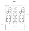
  • Fig. 2 is an explanatory view illustrating a configuration of a branch of the base station 10.
  • an analog unit 110 of the base station 10 includes a branch b0, a branch b1, and a branch b2.
  • Each branch includes an antenna A, a switch S, a transmission analog unit Tx (which may include a digital to-analog (DA) converting unit), and a reception analog unit Rx (which may include an analog-to-digital (AD) converting unit).
  • DA digital to-analog
  • Rx which may include an analog-to-digital (AD) converting unit).
  • Fig. 2 illustrates an example in which the base station 10 includes three branches, the number of branches included in the base station 10 is not limited to three. For example, the number of branches included in the base station 10 may be two or may be four or more.
  • the antenna A configuring each branch is connected to the transmission analog unit Tx through the switch S.
  • the transmission analog unit Tx executes analog processing on a transmission signal supplied from a digital unit 150, and then supplies a high frequency signal which has been subjected to the analog processing to the antenna A.
  • the antenna A converts the high frequency signal supplied from the transmission analog unit Tx into a radio signal, and then transmits the radio signal.
  • the antenna A is connected to the reception analog unit Rx through the switch S.
  • the antenna A converts a received radio signal into a high frequency signal, and then supplies the high frequency signal to the reception analog unit Rx.
  • the reception analog unit Rx executes analog processing on the high frequency signal supplied from the antenna A, and then supplies the reception signal which has been subjected to the analog processing to the digital unit 150.
  • the antenna A, the transmission analog unit Tx, and the reception analog unit Rx have a transfer function (characteristic) that differs according to a branch.
  • the transfer function of the transmission analog unit Tx differs in phase from the transfer function of the reception analog unit Rx.
  • the branch calibration corresponds to a process of acquiring a calibration coefficient K(i) for each branch satisfying the following Formula 1.
  • the branch calibration corresponds to a process of complex-multiplying the transmission signal or the reception signal by the calibration coefficient K(i).
  • the branch b0 transmits a radio signal, and the branch b1 and the branch b2 receive the radio signal transmitted from the branch b0 as illustrated in Fig. 3 .
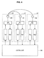
  • the branch b1 and the branch b2 transmit radio signals, and the branch b0 receives the radio signals transmitted from the branch b1 and the branch b2, as illustrated in Fig. 4 .
  • the loop-back transfer function D(i,j) is a coefficient which is measured from a radio signal which passes through a transmission branch i and a transmission branch j.
  • a branch which transmits a radio signal to a plurality of branches and receives radio signals from a plurality of branches is referred to as a "reference branch.”
  • the base station 10 can acquire the calibration coefficient K(i) based on the loop-back transfer function D(i,j) according to the following Formula 2.
  • K 0 1.0
  • Formula 1 used as the calibration condition is verified to be satisfied as expressed in the following Formula 3.
  • a calibration coefficient K(0) of the 0 th branch b0 becomes 1.0 because branch calibration has been performed using the branch b0 as the reference branch.
  • a calibration coefficient K(1) of the 1 st branch b1 becomes 1.0.
  • the plurality of base stations 10 perform branch calibration together using the same branch as the reference branch, it is possible to regularize the ratio of the transfer function of the transmission analog unit Tx and the transfer function of the reception analog unit Rx of all branches in the plurality of base stations 10. In other words, it is considered possible to treat all branches in a plurality of base stations 10 performing CoMP transmission equivalently to a plurality of branches in one device in which branch calibration has been completed.
  • the base station 10 according to an embodiment of the present invention can efficiently perform collaborative branch calibration with another base station that performs CoMP transmission together.
  • the base station 10 according to an embodiment of the present invention will be described below in detail.
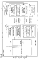
  • Fig. 5 is a functional block diagram illustrating a configuration of the base station 10 according to an embodiment of the present invention.
  • the base station 10 according to an embodiment of the present invention includes an analog unit 110, a backhaul communication unit 120, a digital unit 150, an upper layer unit 180, and a storage unit 190.
  • the backhaul communication unit 120 is an interface used to exchange information with another base station through a wired communication path.
  • the base station 10 transmits/receives a loop-back transfer function obtained in the process of collaborative branch calibration or calibration coefficient update, which will be described later, to/from another base station through the backhaul communication unit 120.
  • the digital unit 150 includes an AD/DA converting unit 152, a demodulation processing unit 160, and a modulation processing unit 170 as illustrated in Fig. 5 .
  • the components of the digital unit 150 may be disposed for each branch.
  • the AD/DA converting unit 152 converts a reception signal of an analog format supplied from the analog unit 110 into a signal of a digital format, and converts a transmission signal of a digital format supplied from the modulation processing unit 170 into a signal of an analog format.
  • the demodulation processing unit 160 performs various kinds of processing to demodulate the reception signal supplied from the AD/DA converting unit 152. For example, the demodulation processing unit 160 performs a Fourier transform, de-mapping, error correction, or the like on the reception signal.
  • the demodulation processing unit 160 includes a synchronizing unit 162 and a transfer function acquiring unit 164.
  • the synchronizing unit 162 acquires synchronization with the reception signal based on a synchronous signal included in the reception signal.
  • the transfer function acquiring unit 164 acquires a loop-back transfer function corresponding to a signal transmission path based on the radio signal received in the process of collaborative branch calibration or calibration coefficient update.
  • the modulation processing unit 170 performs various kinds of processing to modulate a transmission signal supplied from an upper layer 180. For example, the modulation processing unit 170 performs mapping of a transmission signal, an inverse Fourier transform in an IFFT 174, addition of a guide interval, and the like.
  • a calibration coefficient multiplying unit 172 (multiplying unit) of the modulation processing unit 170 complex-multiplies a transmission signal from each branch by a calibration coefficient of each branch read from the storage unit 190 in a frequency domain.
  • the upper layer unit 180 includes an individual calibration coefficient acquiring unit 182, a calibration coefficient adjusting unit 184, and a calibration coefficient update unit 186.
  • the individual calibration coefficient acquiring unit 182 acquires a calibration coefficient K for each branch in the base station 10 through the calculation described in "Individual Branch Calibration.”
  • the calibration coefficient K for each branch in the base station 10 acquired by the individual branch calibration is referred to as an "individual calibration coefficient.”
  • the calibration coefficient adjusting unit 184 initially acquires a calibration coefficient used when the base station 10 performs CoMP with another base station by adjusting the individual calibration coefficient acquired by the individual calibration coefficient acquiring unit 182. Although the details will be described in "3. Initial Acquisition of Calibration Coefficient," the calibration coefficient adjusting unit 184 adjusts the individual calibration coefficient based on a branch calibration result between any one branch of the base station 10 and a branch of another base station. The calibration coefficient obtained through this adjustment is recorded in the storage unit 190.
  • the calibration coefficient update unit 186 updates the calibration coefficient for CoMP acquired by the calibration coefficient adjusting unit 184. This is because the accuracy of the calibration coefficient is considered to be obsolete after a half day due to a change in temperature or the like. However, it is difficult for all the base stations 10 performing CoMP to simultaneously update the calibration coefficient. Further, when the calibration coefficients of some of the base station 10s are updated, mismatching with the calibration coefficient of another base station may occur.
  • the transfer function of the reference branch may change. In this case, mismatching occurs between the updated calibration coefficient of some of the base stations 10 and the existing calibration coefficient of another base station.
  • the calibration coefficient update unit 186 can update the calibration coefficient by an adjustment based on the branch calibration result between any one branch of the base station 10 and a branch of another base station.
  • the calibration coefficient update will be described in detail in "4. Update of Calibration Coefficient.”
  • the configuration of the base station 10 according to an embodiment of the present invention has been described so far. Next, an initial acquisition method of the calibration coefficient used when the base station 10 performs CoMP with another base station will be described in detail.
  • a calibration coefficient of an i th branch of a base station 10i which is acquired by performing branch calibration closed by the base station 10i.
  • a reference branch set when branch calibration closed by the base station 10i is performed.
  • a branch selected for each base station when a plurality of base stations perform collaborative branch calibration. This branch may be different from the reference branch of the individual calibration.
  • a reference branch set when a plurality of base stations perform collaborative branch calibration may be one branch set for each communication terminal 20 or for each relay node.
  • the adjustment coefficient (i) is calculated according to the following Formula 4.
  • the j th branch is the same as the use branch of the collaborative calibration.
  • Adjustment coefficient i collaborative coefficient i use / the individual calibration coefficient i j
  • a j th calibration coefficient of the base station 10i which is used when the base station 10i performs CoMP with another base station.
  • the calibration coefficient (i,j) is calculated according to the following Formula 5.
  • Calibration coefficient i j individual calibration coefficient i j * adjustment coefficient i
  • Fig. 6 is a flowchart illustrating a calibration coefficient acquisition method.
  • each of a plurality of base stations 10 performing CoMP acquires the individual calibration coefficient, for example, by the method described in "Individual Branch Calibration" (step 1).
  • the plurality of base stations 10 perform calibration in collaboration with each other, and acquire the collaborative calibration coefficient (step 2).
  • This collaborative calibration is branch calibration performed between the use branch selected one by one by each base station 10 and the reference branch.
  • the base stations 10 exchange the loop-back transfer function necessary to acquire the collaborative calibration coefficient through the backbone communication unit 120.
  • the number of use branches selected by each base station 10 may be two or more rather than one.
  • each base station 10 calculates the adjustment coefficient based on the individual calibration coefficient and the collaborative calibration coefficient according to Formula 4 (step 3). Further, each base station 10 acquires the final calibration coefficient by complex multiplying the individual calibration coefficient of each branch by the adjustment coefficient calculated in step 3 as expressed in Formula 5 (step 4).
  • step 3 the adjustment coefficient based on the individual calibration coefficient and the collaborative calibration coefficient according to Formula 4
  • step 4 the final calibration coefficient by complex multiplying the individual calibration coefficient of each branch by the adjustment coefficient calculated in step 3 as expressed in Formula 5 (step 4).
  • Figs. 7 and 8 are diagrams for describing an individual calibration process.
  • each of the base stations 10A to 10C performing CoMP first transmits a radio signal through the branch b0 selected as the reference branch, and receives the radio signal through the branches b1 and b2. Through this operation, each of the base stations 10A to 10C can acquire the forward loop-back transfer function D(i,reference)(i,j).
  • D(i,reference) corresponds to "0”
  • "j" in (i,j) corresponds to "1" or "2.”
  • each of the base stations 10A to 10C transmits the radio signal through the branches b1 and b2 and receives the radio signal through the branch b0 as illustrated in Fig. 8 .
  • each of the base stations 10A to 10C can acquire the backward loop-back transfer function D(i,j)(i,reference).
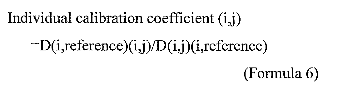
  • each of the base stations 10A to 10C acquires the individual calibration coefficient (i,j) according to the following Formula 6.
  • Individual calibration coefficient i j D i reference ⁇ i j / D i j ⁇ i reference
  • each loop-back transfer function D is a real number, but the loop-back transfer function D may be a complex number.
  • the individual calibration coefficient (i,j) is calculated based on Formula 6 as follows.
  • Individual calibration coefficient A 0 1.0
  • B 0 1.0
  • Fig. 9 and Fig. 10 are diagrams for describing a collaborative calibration process.
  • the use antenna b0 selected from each of the base stations 10A to 10C performing CoMP first receives the radio signal transmitted from the branch of the communication terminal 20A selected as the reference branch. Through this operation, the base stations 10A to 10C can acquire the forward loop-back transfer function D(reference)(i,use).
  • each of the base stations 10A to 10C transmits the radio signal to the reference branch of the communication terminal 20A through the use antenna b0 as illustrated in Fig. 10 .
  • the communication terminal 20A can acquire the backward loop-back transfer function D(i,use)(reference).
  • each of the base stations 10A to 10C acquires the collaborative calibration coefficient (i,j) according to the following Formula 7.
  • Collaborative calibration coefficient i use D reference ⁇ i use / D i use ⁇ reference
  • the loop-back transfer functions are dispersively acquired by the base stations 10A to 10C and the communication terminal 20A.
  • each of the base stations 10A to 10C may exchange the loop-back transfer function necessary to acquire the collaborative calibration coefficient using a backhaul or wireless communication.
  • the collaborative calibration coefficient (i,use) is calculated based on Formula 7 as follows.
  • Each base station 10 calculates the adjustment coefficient (i) according to Formula 4. Specifically, when the individual calibration coefficient (i,j) and the collaborative calibration coefficient (i,use) have been obtained, each base station 10 calculates the adjustment coefficient (i) as follows.
  • Each base station 10 calculates the final calibration coefficient (i,j) of each branch according to Formula 5. Specifically, when the individual calibration coefficient (i,j) and the adjustment coefficient (i) have been obtained, each base station 10 calculates the final calibration coefficient (i,j) of each branch as follows.
  • a plurality of base stations 10 perform branch calibration in collaboration with each other, and thus it is possible to acquire the matching calibration coefficient among all branches of a plurality of base stations 10.
  • a method of updating some calibration coefficients will be described in detail.
  • a base station that cooperates to update the calibration coefficient of the target base station.
  • a calibration coefficient of the i-th branch of the base station 10i which is acquired by performing branch calibration closed by the base station 10i.
  • a calibration coefficient of the use branch of the base station 10i which is acquired by collaborative calibration.
  • a collaborative calibration coefficient (i,use) corrected by the correction coefficient Specifically, a value obtained by multiplying the correction coefficient by the collaborative calibration coefficient (i,use).
  • the calibration coefficient (i,j) is calculated according to the following Formula 9.
  • Calibration coefficient i j individual calibration coefficient i j * update coefficient i
  • Fig. 11 is a flowchart illustrating a calibration coefficient update method. As illustrated in Fig. 11 , first, a target base station whose calibration coefficient for CoMP needs to be updated and a cooperative base station that cooperates in updating are decided (step 1). Subsequently, the target base station performs individual calibration, and acquires the individual calibration coefficient of each branch (step 2).
  • the target base station and the cooperative base station perform calibration in collaboration with each other, and acquire the collaborative calibration coefficient (step 3).
  • This collaborative calibration is branch calibration performed between the use branch selected individually by the target base station and the cooperative base station and the reference branch.
  • the cooperative base station calculates the correction coefficient used to match the collaborative calibration coefficient of the use branch of the cooperative base station acquired in step 3 with the calibration coefficient of the use branch currently stored in the storage unit 190 (step 4).
  • the target base station multiplies the collaborative calibration coefficient of the use branch of the target base station acquired in step 3 by the correction coefficient calculated in step 4, and calculates the corrected collaborative calibration coefficient (step 5). Then, the target base station calculates the update coefficient according to Formula 8 (step 6), and then acquires the final calibration coefficient according to Formula 9 (step 7).
  • the target base station calculates the update coefficient according to Formula 8 (step 6), and then acquires the final calibration coefficient according to Formula 9 (step 7).
  • the target base station is the base station 10 whose calibration coefficient for CoMP is to be updated as described above.
  • the accuracy of the calibration coefficient degrades with the lapse of time.
  • the base station 10 may decide itself as the target base station when a predetermined time elapses after the calibration coefficient for CoMP is acquired or updated. Further, the base station 10 may decide a base station present at the position at which collaborative calibration with the target base station is performed as the cooperative base station. In the following, the process will be described under the assumption that among the base stations 10A to 10C whose calibration coefficients are acquired by the process illustrated Figs. 9 and 10 , the base station 10A is decided as a target cell, and the base station 10C is decided as a cooperative cell.
  • the base station 10A decided as the target cell base station acquires the forward loop-back transfer function D(A,reference)(A,j) and the backward loop-back transfer function D(A,j)(A,reference), and then acquires the individual calibration coefficient (A,j) based on the functions.
  • the individual calibration coefficient (A,j) has been acquired.
  • the individual calibration coefficient (A,j) acquired at the time of update is expected to be different from the individual calibration coefficient (A,j) acquired at the time of initial acquisition.
  • Individual calibration coefficient A 0 1.0
  • a 1 0.6
  • a 2 2.2
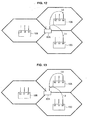
  • Fig. 12 and Fig. 13 are diagrams for describing a collaborative calibration process.
  • the use antennas b0 selected from the base station 10A serving as the target base station and the cooperative base station 10C first receive the radio signal transmitted from the branch of the communication terminal 20A selected as the reference branch. Through this operation, the base stations 10A and 10C can acquire the forward loop-back transfer function D(reference)(i,use).
  • each of the base stations 10A and 10C transmits the radio signal to the reference branch of the communication terminal 20A through the use antenna b0 as illustrated in Fig. 13 .
  • the communication terminal 20A can acquire the backward loop-back transfer function D(i,use)(reference).
  • each of the base stations 10A and 10C acquires the collaborative calibration coefficient (i,j) according to Formula 7.
  • the loop-back transfer functions are dispersively acquired by the base stations 10A and 10C and the communication terminal 20A.
  • the base stations 10A and 10C may exchange the loop-back transfer function necessary to acquire the collaborative calibration coefficient using a backhaul or wireless communication.
  • the collaborative calibration coefficient (i,use) is calculated based on Formula 7 as follows.
  • the base station 10C serving as the cooperative base station calculates a coefficient used to match the collaborative calibration coefficient (C,0) of the use branch of the cooperative base station acquired in step 3 with the current calibration coefficient (C,0) of the use branch of the base station 10C.
  • the base station 10A serving as the target base station multiplies the collaborative calibration coefficient (A,0) of the use branch of the base station 10A acquired in step 3 by the correction coefficient calculated in step 4, and calculates the corrected collaborative calibration coefficient (i,use).
  • the base station 10A serving as the target base station calculates the final calibration coefficient (A,j) of each branch according to Formula 9. Specifically, when the individual calibration coefficient (A,j) and the update coefficient (A) have been obtained, the base station 10A calculates the final calibration coefficient (A,j) of each branch as follows.
  • the base station 10 can acquire and update the calibration coefficient for CoMP by adjusting the individual calibration coefficient acquired by individually performing branch calibration to match the individual calibration coefficient of another base station.
  • steps of the processes of the base station 10 of the present disclosure need not necessarily be processed in time series according to an order described as a flowchart.
  • steps of the processes of the base station 10 of the present disclosure may be processed in an order different from an order described as a flowchart or in parallel.
  • a computer program may be created that causes hardware, which is installed in the base station 10 such as a central processing unit (CPU), a read only memory (ROM), and a random access memory (RAM) to perform functions equivalent to the components of the base station 10. Further, a storage medium storing the computer program is also provided.
  • hardware which is installed in the base station 10 such as a central processing unit (CPU), a read only memory (ROM), and a random access memory (RAM) to perform functions equivalent to the components of the base station 10.
  • a storage medium storing the computer program is also provided.

Landscapes

  • Engineering & Computer Science (AREA)
  • Computer Networks & Wireless Communication (AREA)
  • Signal Processing (AREA)
  • Physics & Mathematics (AREA)
  • Electromagnetism (AREA)
  • Mobile Radio Communication Systems (AREA)
  • Radio Transmission System (AREA)

Abstract

Provided is a base station including a plurality of branches that perform CoMP transmission with another base station, a multiplying unit that multiplies a transmission signal from each of the plurality of branches by a calibration coefficient of each of the plurality of branches, wherein the calibration coefficient is a coefficient obtained by adjusting an individual calibration coefficient acquired by branch calibration between the plurality of branches in the base station based on a branch calibration result between a branch of the base station and a branch of the other base station.

Description

    Technical Field
  • The present invention relates to a base station, a communication system, and a communication method.
  • Background Art
  • Recently, introduction of a 4th generation cellular system (4G) has been under discussion in order to achieve improvement of additional performance of wireless communication. In 4G, techniques such as a relay technique, a carrier aggregation, and a coordinated multiple point transmission and reception (CoMP) are attracting attention.
  • The relay technique refers to a technique by which a relay node relays communication between a base station (for example, a macro cell base station) and a communication terminal, and the relay technique is important in improving the throughput at a cell edge of a base station. The carrier aggregation is a technique in which a use bandwidth is increased and a maximum throughput is improved by collectively treating a plurality of frequency bands each having a bandwidth of 20 MHz. CoMP is a technique by which a plurality of base stations collaborate with each other to perform data communication with a communication terminal, and the coverage of high-data-rate communication can be increased.
  • In further detail, CoMP refers to a technique by which a plurality of base stations simultaneously perform data communication with one communication terminal. According to this technique, since branches of a plurality of base stations can be used for data communication, an antenna gain and a signal to interference plus noise ratio (SINR) can be improved.
  • Here, it is assumed that a base station has calculated a weight of a branch based on a channel matrix of an uplink from a communication terminal and then has obtained reception directivity. In this case, when a weight of a branch is used even at the time of transmission, transmission directivity matching reception directivity is considered to be obtained. However, since a transfer function of a transmission analog unit and a transfer function of a reception analog unit of each branch are different from each other, actual transmission directivity does not match reception directivity.
  • Problems caused due to the difference between the transfer function of the transmission analog unit and the transfer function of the reception analog unit of each branch are solved such that each base station individually performs branch calibration and a calibration coefficient of each branch. The calibration coefficient is a coefficient used to regularize a ratio of the transfer function of the transmission analog unit and the transfer function of the reception analog unit of each branch in one base station. The branch calibration is disclosed in, for example, Patent Literature 1 and Patent Literature 2.
  • Citation List Patent Literature
  • Patent Literature 1:
    JP 2009-188546A
    Patent Literature 2:
    JP 2007-116489A
    Summary of Invention Technical Problem
  • However, in the above-described individual branch calibration, it is possible to obtain the calibration coefficient used to regularize the ratio of the transfer function of the transmission analog unit and the transfer function of the reception analog unit of each branch in one base station, but it is difficult to regularize the ratios of the transfer function of the transmission analog unit and the transfer function of the reception analog unit of all branches in a plurality of base stations. For this reason, using only a method in which each base station individually performs branch calibration, it is difficult to treat all branches in a plurality of base stations performing CoMP equivalently to a plurality of branches in one device in which branch calibration has been completed. In other words, when CoMP is performed using branches of a plurality of base stations in an aggregate manner, it is difficult to match uplink directivity with downlink directivity.
  • Further, when each base station individually performs branch calibration, each base station individually forms directivity and performs a CoMP, but efficient communication is expected to be difficult to perform. For example, when three base stations having two branches individually perform branch calibration, it is possible to implement MIMO communication of 2×N of 3 sets (N is the number of branches at a communication terminal side), but it is difficult to implement MIMO communication of 6×N of a higher throughput.
  • In this regard, the present invention is made in light of the above-mentioned problems, and it is an object of the present invention to provide a base station, a communication system, and a communication method, which are novel and improved, and which are capable of efficiently performing collaborative branch calibration through branches in a plurality of base stations.
  • Solution to Problem
  • In order to solve the above-mentioned problems, according to an aspect of the present invention, there is provided a base station including a plurality of branches that perform CoMP transmission with another base station and a multiplying unit that multiplies a transmission signal from each of the plurality of branches by a calibration coefficient of each of the plurality of branches, wherein the calibration coefficient is a coefficient obtained by adjusting an individual calibration coefficient acquired by branch calibration between the plurality of branches in the base station based on a branch calibration result between a branch of the base station and a branch of the other base station.
  • The calibration coefficient of each of the plurality of branches may be a coefficient obtained by adjusting the individual calibration coefficient of each of the plurality of branches based on an adjustment coefficient obtained by dividing a collaborative calibration coefficient of the branch of the base station acquired by branch calibration between a branch of the base station and a branch of the other base station by the individual calibration coefficient of the branch of the base station.
  • The calibration coefficient of each of the plurality of branches may be a value obtained by multiplying the individual calibration coefficient of each of the plurality of branches by the adjustment coefficient.
  • Further, in order to solve the above-mentioned problem, according to another aspect of the present invention, there is provided a base station including a plurality of branches that perform CoMP transmission with another base station, a storage unit that stores a calibration coefficient for each of the plurality of branches, and a multiplying unit that multiplies a transmission signal from each of the plurality of branches by the calibration coefficient, wherein the calibration coefficient of each of the plurality of branches is updated by adjusting an individual calibration coefficient acquired by branch calibration between the plurality of branches in the base station based on a branch calibration result between a branch of the base station and a branch of the other base station.
  • The calibration coefficient of each of the plurality of branches may be updated by adjusting the individual calibration coefficient of each of the plurality of branches based on an update coefficient obtained by branch calibration between a branch of the base station and a branch of the other base station, the update coefficient may be a coefficient obtained by dividing a value obtained by multiplying a collaborative calibration coefficient of the branch of the base station acquired by branch calibration between a branch of the base station and a branch of the other base station by a correction coefficient by the individual calibration coefficient of the branch of the base station, and the correction coefficient may be a coefficient causing a collaborative calibration coefficient of the branch of the other base station acquired by branch calibration between a branch of the base station and a branch of the other base station to be used as an in-use collaborative calibration coefficient of the branch of the other base station.
  • Further, in order to solve the above-mentioned problem, according to another aspect of the present invention, there is provided a communication system including a plurality of base stations, each of the plurality of base stations including a plurality of branches that perform CoMP transmission with another base station, and a multiplying unit that multiplies a transmission signal from each of the plurality of branches by a calibration coefficient of each of the plurality of branches, wherein the calibration coefficient is a coefficient obtained by adjusting an individual calibration coefficient acquired by branch calibration between the plurality of branches in the base station based on a branch calibration result between a branch of the base station and a branch of the other base station.
  • Further, in order to solve the above-mentioned problem, according to another aspect of the present invention, there is provided a communication system including a plurality of base stations, each of the plurality of base stations including a plurality of branches that perform CoMP transmission with another base station, a storage unit that stores a calibration coefficient for each of the plurality of branches, and a multiplying unit that multiplies a transmission signal from each of the plurality of branches by the calibration coefficient, wherein the calibration coefficient of each of the plurality of branches is updated by adjusting an individual calibration coefficient acquired by branch calibration between the plurality of branches in the base station based on a branch calibration result between a branch of the base station and a branch of the other base station.

  • Further, in order to solve the above-mentioned problem, according to another aspect of the present invention, there is provided a communication method including, performing, by each of a plurality of base stations, each of which includes a plurality of branches and performs CoMP transmission, branch calibration between the plurality of branches in a base station, and acquiring an individual calibration coefficient corresponding to each of the plurality of branches, performing branch calibration between branches of the plurality of base stations, acquiring a calibration coefficient by adjusting the individual calibration coefficient corresponding to each of the plurality of branches based on a branch calibration result between branches of the plurality of base stations, and multiplying a transmission signal from each of the plurality of branches of the base station by the calibration coefficient of each of the plurality of branches.
  • Advantageous Effects of Invention
  • As described above, according to the present invention, it is possible to efficiently perform collaborative branch calibration through branches in a plurality of base stations.
  • Brief Description of Drawings
    • [Fig. 1] Fig. 1 is an explanatory view illustrating a configuration of a communication system 1 according to an embodiment of the present invention.
    • [Fig. 2] Fig. 2 is an explanatory view illustrating a configuration of a branch of the base station 10.
    • [Fig. 3] Fig. 3 is an explanatory view illustrating an individual branch calibration process.
    • [Fig. 4] Fig. 4 is an explanatory view illustrating an individual branch calibration process.
    • [Fig. 5] Fig. 5 is an explanatory view illustrating a configuration of the base station 10.
    • [Fig. 6] Fig. 6 is a flowchart illustrating an operation of the base station 10.
    • [Fig. 7] Fig. 7 is an explanatory view illustrating a process of initially acquiring calibration for CoMP.
    • [Fig. 8] Fig. 8 is an explanatory view illustrating a process of initially acquiring calibration for CoMP.
    • [Fig. 9] Fig. 9 is an explanatory view illustrating a process of initially acquiring calibration for CoMP.
    • [Fig. 10] Fig. 10 is an explanatory view illustrating a process of initially acquiring calibration for CoMP.
    • [Fig. 11] Fig. 11 is a flowchart illustrating an operation of the base station 10.
    • [Fig. 12] Fig. 12 is an explanatory view illustrating a process of updating calibration for CoMP.
    • [Fig. 13] Fig. 13 is an explanatory view illustrating a process of updating calibration for CoMP.
    Description of Embodiments
  • Hereinafter, preferred embodiments of the present invention will be described in detail with reference to the appended drawings. Note that, in this specification and the drawings, elements that have substantially the same function and structure are denoted with the same reference signs, and repeated explanation is omitted.
  • Further, in this specification and the drawings, a plurality of elements having substantially the same function and structure may be distinguished from each other such that different letters are suffixed to the same reference signal. For example, a plurality of elements having substantially the same function and structure are distinguished from each other such as base stations 10A, 10B and 10C as necessary. However, when it is unnecessary to individually distinguish a plurality of elements having substantially the same function and structure, only the same reference signal is attached. For example, when it is unnecessary to particularly distinguish base stations 10A, 10B, and 10C, they are referred to simply as a base station 10.
  • Further, an "embodiment for embodying the invention" will be described in the following order.
    1. 1. Overall Configuration of Communication System
    2. 2. Configuration of Base Station
    3. 3. Initial Acquisition of Calibration Coefficient
    4. 4. Update of Calibration Coefficient
    5. 5. Summary
    <1. Overall Configuration of Communication System>
  • First, an overall configuration of a communication system 1 according to an embodiment of the present invention will be described with reference to Fig. 1.
  • Fig. 1 is an explanatory view illustrating a configuration of the communication system 1 according to an embodiment of the present invention. As illustrated in Fig. 1, the communication system 1 according to an embodiment of the present invention includes a plurality of base stations 10 and a communication terminal 20.
  • The communication terminal 20 (UE: User Equipment) performs communication with the base station 10 under control of the base station 10. For example, the communication terminal 20 performs a reception process in a downlink resource block assigned by the base station 10, and performs a transmission process in an uplink resource block.
  • The communication terminal 20 may be an information processing device such as a personal computer (PC), a video processing device for home use (a DVD recorder, a videocassette recorder, and the like), a personal digital assistant (PDA), a game machine for home use, or a household electrical appliance. Further, the communication terminal 20 may be a mobile communication device such as a portable telephone, a personal handyphone system (PHS), a portable music reproducing device, a portable video processing device, or a portable game machine.
  • The base station 10 performs communication with the communication terminal 20 located within its coverage. For example, a base station 10A can perform communication with a communication terminal 20A located within the coverage of the base station 10A. In this disclosure, the description will proceed under the assumption that the base station 10 is a macro cell base station (eNodeB), but the base station 10 is not limited to the macro cell base station. For example, the base station 10 may be a pico cell/micro cell base station which is smaller in maximum transmission power than a macro cell base station or may be a relay node or a femto cell base station.
  • Each base station 10 is connected in a wired manner, and can exchange information with another base station 10 through wired communication. The base station 10 can implement CoMP which is expected as a next generation technology based on this information exchange. CoMP is classified roughly into joint processing, and coordinated scheduling and/or beamforming.
  • The joint processing of the former is a technique by which a plurality of base stations 10 simultaneously perform data communication with one communication terminal 20. An example in which the base station 10A, the base station 10B, and the base station 10C simultaneously transmit data to the communication terminal 20A as illustrated in Fig. 1 corresponds to the joint processing. According to the joint processing, branches (antennas and analog circuits) of a plurality of base stations 10 can be used for data communication, and the antenna gain and the SINR can be improved.
  • Further, when downlink joint processing is performed, it is necessary to distribute transmission data to be directed to the communication terminal 20 to a plurality of base stations 10 in advance using a wired communication path, called, for example, a backhaul, between the base stations 10. Further, uplink joint processing is performed by aggregating data which a plurality of base stations 10 have received from the communication terminal 20.
  • For example, a method of aggregating data at a bit level after decoding by each base station 10, a method of aggregating data at a soft bit stage before decoding by each base station 10, or a method of aggregating data before de-mapping by each base station 10 may be used as a data aggregation method. As an amount of aggregated data increases after a subsequent demodulation process is performed by each base station 10, an amount of data exchanged through a backhaul increases, but a performance tends to be improved.
  • The coordinated scheduling and/or beam forming of the latter is a technique by which data transmission is performed only by the one base station 10, and scheduling (control of deciding a resource block to be assigned to each communication terminal 20) is performed based on collaboration of a plurality of base stations 10. According to the coordinated scheduling and/or beam forming, interference between a plurality of base stations 10 can be easily avoided by scheduling adjustment.
  • The present invention is focused particularly on the joint processing of the former among the two types of CoMPs described above. The joint processing is classified roughly into non-coferent joint processing and coferent joint processing.
  • The coferent joint processing is a method in which a transmission timing of data from each base station 10 is adjusted such that phases of pieces of data arriving at the communication terminal 20 from the base station 10 match each other. On the other hand, the non-coferent joint processing is a method in which each base station 10 transmits data without adjusting a transmission timing of data from each base station 10. Thus, the coferent joint processing is higher in performance than the non-coferent joint processing. However, in order to perform the coferent joint processing, it is necessary to calculate an adjustment amount of a transmission timing of each base station 10 for each communication terminal 20, and thus there is a disadvantage that processing becomes complicated.
  • In this regard, it is desirable to treat all branches in the plurality of base stations 10 performing CoMP (which represents the joint processing; the same hereinafter) transmission equivalently to a plurality of branches in one device in which branch calibration has been completed. Here, when such treatment can be made, it is possible to match uplink directivity with downlink directivity when CoMP is performed using the branches of the plurality of base stations 10 in an aggregation manner, and thus it is unnecessary to adjust a transmission timing of each base station 10 for each communication terminal 20.
  • However, even when each base station 10 individually performs branch calibration, not all branches in the plurality of base stations 10 are treated equivalently to a plurality of branches in one device in which branch calibration has been completed. Thus, even when each base station 10 individually performs branch calibration, it is difficult to match uplink directivity with downlink directivity when CoMP is performed using the branches of the plurality of base stations 10 in an aggregation manner. The reason will be described below together with the details of individual calibration and a branch configuration of the base station 10.
  • (Individual Branch Calibration)
  • Fig. 2 is an explanatory view illustrating a configuration of a branch of the base station 10. As illustrated in Fig. 2, an analog unit 110 of the base station 10 includes a branch b0, a branch b1, and a branch b2. Each branch includes an antenna A, a switch S, a transmission analog unit Tx (which may include a digital to-analog (DA) converting unit), and a reception analog unit Rx (which may include an analog-to-digital (AD) converting unit). Although Fig. 2 illustrates an example in which the base station 10 includes three branches, the number of branches included in the base station 10 is not limited to three. For example, the number of branches included in the base station 10 may be two or may be four or more.
  • At the time of transmission, the antenna A configuring each branch is connected to the transmission analog unit Tx through the switch S. The transmission analog unit Tx executes analog processing on a transmission signal supplied from a digital unit 150, and then supplies a high frequency signal which has been subjected to the analog processing to the antenna A. The antenna A converts the high frequency signal supplied from the transmission analog unit Tx into a radio signal, and then transmits the radio signal.
  • Meanwhile, at the time of reception, the antenna A is connected to the reception analog unit Rx through the switch S. The antenna A converts a received radio signal into a high frequency signal, and then supplies the high frequency signal to the reception analog unit Rx. The reception analog unit Rx executes analog processing on the high frequency signal supplied from the antenna A, and then supplies the reception signal which has been subjected to the analog processing to the digital unit 150.
  • The antenna A, the transmission analog unit Tx, and the reception analog unit Rx have a transfer function (characteristic) that differs according to a branch. In addition, even inside the same branch, the transfer function of the transmission analog unit Tx differs in phase from the transfer function of the reception analog unit Rx. The problems caused due to the difference between the transfer function of the transmission analog unit Tx and the transfer function of the reception analog unit Rx of each branch in the base station 10 are solved such that the base station 10 individually performs branch calibration. The branch calibration individually performed by the base station 10 will be concretely described below.
  • Let us assume that a branch number is i, a transfer function of a transmission analog unit Tx of an ith branch is Tx(i), and a transfer function of a reception analog unit Rx of the ith branch is Rx(i). In this case, the branch calibration corresponds to a process of acquiring a calibration coefficient K(i) for each branch satisfying the following Formula 1. In a broad sense, the branch calibration corresponds to a process of complex-multiplying the transmission signal or the reception signal by the calibration coefficient K(i).
  • Tx 0 * K 0 / Rx 0 = Tx 1 * K 1 / Rx 1 = Tx 2 * K 2 / Rx 2
    Figure imgb0001
  • In order to acquire the calibration coefficient K(i), first, the branch b0 transmits a radio signal, and the branch b1 and the branch b2 receive the radio signal transmitted from the branch b0 as illustrated in Fig. 3. Next, the branch b1 and the branch b2 transmit radio signals, and the branch b0 receives the radio signals transmitted from the branch b1 and the branch b2, as illustrated in Fig. 4.
  • As a result, the following loop-back transfer function D(i,j) is measured. The loop-back transfer function D(i,j) is a coefficient which is measured from a radio signal which passes through a transmission branch i and a transmission branch j. A branch which transmits a radio signal to a plurality of branches and receives radio signals from a plurality of branches is referred to as a "reference branch."
  • D 0 1 = Tx 0 * Rx 1
    Figure imgb0002
    D 0 2 = Tx 0 * Rx 2
    Figure imgb0003
    D 1 0 = Tx 1 * Rx 0
    Figure imgb0004
    D 2 0 = Tx 2 * Rx 0
    Figure imgb0005
  • The base station 10 can acquire the calibration coefficient K(i) based on the loop-back transfer function D(i,j) according to the following Formula 2.
  • K 0 = 1.0 K 1 = D 0 1 / D 1 0 = Rx 1 / Tx 1 * Tx 0 / Rx 0 K 2 = D 0 2 / D 2 0 = Rx 2 / Tx 2 * Tx 0 / Rx 0
    Figure imgb0006
  • Here, when verification of Formula 2 is performed, Formula 1 used as the calibration condition is verified to be satisfied as expressed in the following Formula 3.
  • Tx 0 * K 0 / Rx 0 = Tx 0 / Rx 0 Tx 1 * K 1 / Rx 1 = Tx 0 / Rx 0 Tx 2 * K 2 / Rx 2 = Tx 0 / Rx 0
    Figure imgb0007
  • Further, as expressed in Formula 2, a calibration coefficient K(0) of the 0th branch b0 becomes 1.0 because branch calibration has been performed using the branch b0 as the reference branch. Thus, when branch calibration has been performed using the branch b1 as the reference branch, a calibration coefficient K(1) of the 1st branch b1 becomes 1.0.
  • (Problem of Individual Branch Calibration)
  • As described above, according to individual branch calibration, it is possible to regularize the ratio of the transfer function of the transmission analog unit Tx and the transfer function of the reception analog unit Rx of all branches in each base station 10. However, even when the individual branch calibration is performed by each base station 10, since reference antennas of the individual branch calibration by the base stations 10 are different from each other, it is difficult to regularize the ratio of the transfer function of the transmission analog unit Tx and the transfer function of the reception analog unit Rx of branches in a different base station 10. In other words, it is difficult to treat all branches in a plurality of base stations 10 performing CoMP transmission equivalently to a plurality of branches in one device in which branch calibration has been completed.
  • Meanwhile, when the plurality of base stations 10 perform branch calibration together using the same branch as the reference branch, it is possible to regularize the ratio of the transfer function of the transmission analog unit Tx and the transfer function of the reception analog unit Rx of all branches in the plurality of base stations 10. In other words, it is considered possible to treat all branches in a plurality of base stations 10 performing CoMP transmission equivalently to a plurality of branches in one device in which branch calibration has been completed.
  • However, in the method in which the plurality of base stations 10 perform branch calibration together using the same branch as the reference branch, for example, it is necessary to sequentially transmit radio signals from all branches of a calibration target, and thus a commensurate time is expended. As a result, it is also feared that the branch calibration will adversely affect communication performed by the communication terminal 20.
  • In this context, an embodiment of the present disclosure has been made in light of the foregoing. The base station 10 according to an embodiment of the present invention can efficiently perform collaborative branch calibration with another base station that performs CoMP transmission together. The base station 10 according to an embodiment of the present invention will be described below in detail.
  • <2. Configuration of Base Station>
  • Fig. 5 is a functional block diagram illustrating a configuration of the base station 10 according to an embodiment of the present invention. As illustrated in Fig. 5, the base station 10 according to an embodiment of the present invention includes an analog unit 110, a backhaul communication unit 120, a digital unit 150, an upper layer unit 180, and a storage unit 190.
  • The backhaul communication unit 120 is an interface used to exchange information with another base station through a wired communication path. For example, the base station 10 transmits/receives a loop-back transfer function obtained in the process of collaborative branch calibration or calibration coefficient update, which will be described later, to/from another base station through the backhaul communication unit 120.
  • The digital unit 150 includes an AD/DA converting unit 152, a demodulation processing unit 160, and a modulation processing unit 170 as illustrated in Fig. 5. The components of the digital unit 150 may be disposed for each branch.
  • The AD/DA converting unit 152 converts a reception signal of an analog format supplied from the analog unit 110 into a signal of a digital format, and converts a transmission signal of a digital format supplied from the modulation processing unit 170 into a signal of an analog format.
  • The demodulation processing unit 160 performs various kinds of processing to demodulate the reception signal supplied from the AD/DA converting unit 152. For example, the demodulation processing unit 160 performs a Fourier transform, de-mapping, error correction, or the like on the reception signal. The demodulation processing unit 160 includes a synchronizing unit 162 and a transfer function acquiring unit 164.
  • The synchronizing unit 162 acquires synchronization with the reception signal based on a synchronous signal included in the reception signal. The transfer function acquiring unit 164 acquires a loop-back transfer function corresponding to a signal transmission path based on the radio signal received in the process of collaborative branch calibration or calibration coefficient update.
  • The modulation processing unit 170 performs various kinds of processing to modulate a transmission signal supplied from an upper layer 180. For example, the modulation processing unit 170 performs mapping of a transmission signal, an inverse Fourier transform in an IFFT 174, addition of a guide interval, and the like. A calibration coefficient multiplying unit 172 (multiplying unit) of the modulation processing unit 170 complex-multiplies a transmission signal from each branch by a calibration coefficient of each branch read from the storage unit 190 in a frequency domain.
  • The upper layer unit 180 includes an individual calibration coefficient acquiring unit 182, a calibration coefficient adjusting unit 184, and a calibration coefficient update unit 186.
  • The individual calibration coefficient acquiring unit 182 acquires a calibration coefficient K for each branch in the base station 10 through the calculation described in "Individual Branch Calibration." In the following, the calibration coefficient K for each branch in the base station 10 acquired by the individual branch calibration is referred to as an "individual calibration coefficient."
  • The calibration coefficient adjusting unit 184 initially acquires a calibration coefficient used when the base station 10 performs CoMP with another base station by adjusting the individual calibration coefficient acquired by the individual calibration coefficient acquiring unit 182. Although the details will be described in "3. Initial Acquisition of Calibration Coefficient," the calibration coefficient adjusting unit 184 adjusts the individual calibration coefficient based on a branch calibration result between any one branch of the base station 10 and a branch of another base station. The calibration coefficient obtained through this adjustment is recorded in the storage unit 190.
  • The calibration coefficient update unit 186 updates the calibration coefficient for CoMP acquired by the calibration coefficient adjusting unit 184. This is because the accuracy of the calibration coefficient is considered to be obsolete after a half day due to a change in temperature or the like. However, it is difficult for all the base stations 10 performing CoMP to simultaneously update the calibration coefficient. Further, when the calibration coefficients of some of the base station 10s are updated, mismatching with the calibration coefficient of another base station may occur.
  • For example, even when some of the base stations 10 update the calibration coefficient using the same branch as at the time of initial acquisition as the reference branch, the transfer function of the reference branch may change. In this case, mismatching occurs between the updated calibration coefficient of some of the base stations 10 and the existing calibration coefficient of another base station.
  • In this regard, the calibration coefficient update unit 186 can update the calibration coefficient by an adjustment based on the branch calibration result between any one branch of the base station 10 and a branch of another base station. The calibration coefficient update will be described in detail in "4. Update of Calibration Coefficient."
  • <3. Initial Acquisition of Calibration Coefficient>
  • The configuration of the base station 10 according to an embodiment of the present invention has been described so far. Next, an initial acquisition method of the calibration coefficient used when the base station 10 performs CoMP with another base station will be described in detail.
  • First, the terminology related to the calibration coefficient initial acquisition is defined as follows.
  • · Individual Calibration Coefficient (i,j)
  • A calibration coefficient of an ith branch of a base station 10i, which is acquired by performing branch calibration closed by the base station 10i.
  • · Reference Branch of Individual Calibration
  • A reference branch set when branch calibration closed by the base station 10i is performed.
  • · Forward Loop-Back Transfer Function D(i,reference)(i,j)
  • A loop-back transfer function from the reference branch of the base station 10i to a jth branch of the base station 10i.
  • · Backward Loop-Back Transfer Function D(i,j)(i,reference)
  • A loop-back transfer function from the jth branch of the base station 10i to the reference branch of the base station 10i.
  • · Use Branch of Each Base Station of Collaborative Calibration
  • A branch selected for each base station when a plurality of base stations perform collaborative branch calibration. This branch may be different from the reference branch of the individual calibration.
  • · Reference Branch of Collaborative Calibration
  • A reference branch set when a plurality of base stations perform collaborative branch calibration. This branch may be one branch set for each communication terminal 20 or for each relay node.
  • · Forward Loop-Back Transfer Function D(reference)(i,use)
  • A loop-back transfer function from the reference branch of collaborative calibration to the use branch of the base station 10i
  • · Backward Loop-Back Transfer Function D(i,use)(reference)
  • A loop-back transfer function from the use branch of the base station 10i to the reference branch of collaborative calibration.
  • · Collaborative Calibration Coefficient (i,use)
  • A calibration coefficient of the use branch of the base station 10i acquired by collaborative calibration
  • · Adjustment Coefficient (i)
  • A coefficient used to adjust the individual calibration coefficient (i,j) of the base station 10i and acquire a final calibration coefficient. The adjustment coefficient (i) is calculated according to the following Formula 4. In Formula 4, the jth branch is the same as the use branch of the collaborative calibration. Adjustment coefficient i = collaborative coefficient i use / the individual calibration coefficient i j
    Figure imgb0008
  • · Calibration Coefficient (i,j)
  • A jth calibration coefficient of the base station 10i, which is used when the base station 10i performs CoMP with another base station. The calibration coefficient (i,j) is calculated according to the following Formula 5. Calibration coefficient i j = individual calibration coefficient i j * adjustment coefficient i
    Figure imgb0009
  • (Outline)
  • Next, an outline of a calibration coefficient acquisition method will be described with reference to Fig. 6. Fig. 6 is a flowchart illustrating a calibration coefficient acquisition method. First, each of a plurality of base stations 10 performing CoMP acquires the individual calibration coefficient, for example, by the method described in "Individual Branch Calibration" (step 1).
  • Thereafter, the plurality of base stations 10 perform calibration in collaboration with each other, and acquire the collaborative calibration coefficient (step 2). This collaborative calibration is branch calibration performed between the use branch selected one by one by each base station 10 and the reference branch. The base stations 10 exchange the loop-back transfer function necessary to acquire the collaborative calibration coefficient through the backbone communication unit 120. The number of use branches selected by each base station 10 may be two or more rather than one.
  • Subsequently, each base station 10 calculates the adjustment coefficient based on the individual calibration coefficient and the collaborative calibration coefficient according to Formula 4 (step 3). Further, each base station 10 acquires the final calibration coefficient by complex multiplying the individual calibration coefficient of each branch by the adjustment coefficient calculated in step 3 as expressed in Formula 5 (step 4). Each step will be described below in detail using a concrete example.
  • (Step 1: Acquisition of Individual Calibration Coefficient)
  • Figs. 7 and 8 are diagrams for describing an individual calibration process. As illustrated in Fig. 7, each of the base stations 10A to 10C performing CoMP first transmits a radio signal through the branch b0 selected as the reference branch, and receives the radio signal through the branches b1 and b2. Through this operation, each of the base stations 10A to 10C can acquire the forward loop-back transfer function D(i,reference)(i,j). In this example in which the branch b0 is selected as the reference branch, "reference" in (i,reference) corresponds to "0," and "j" in (i,j) corresponds to "1" or "2."
  • Subsequently, each of the base stations 10A to 10C transmits the radio signal through the branches b1 and b2 and receives the radio signal through the branch b0 as illustrated in Fig. 8. Through this operation, each of the base stations 10A to 10C can acquire the backward loop-back transfer function D(i,j)(i,reference).
  • Then, each of the base stations 10A to 10C acquires the individual calibration coefficient (i,j) according to the following Formula 6. Individual calibration coefficient i j = D i reference i j / D i j i reference
    Figure imgb0010
  • Here, it is assumed that the following values have been obtained as the forward loop-back transfer function D(i,reference)(i,j) and the backward loop-back transfer function D(i,j)(i,reference) as illustrated in Figs. 7 and 8. In the following, for the sake of simplification of description, each loop-back transfer function D is a real number, but the loop-back transfer function D may be a complex number. D A reference A 1 = 2.0
    Figure imgb0011
    D A reference A 2 = 3.0
    Figure imgb0012
    D A 1 A reference = 4.0
    Figure imgb0013
    D A 2 A reference = 1.5
    Figure imgb0014
    D B reference B 1 = 2.0
    Figure imgb0015
    D B reference B 2 = 1.0
    Figure imgb0016
    D B 1 B reference = 1.0
    Figure imgb0017
    D B 2 B reference = 2.0
    Figure imgb0018
    D C reference C 1 = 3.0
    Figure imgb0019
    D C reference C 2 = 4.0
    Figure imgb0020
    D C 1 C reference = 1.5
    Figure imgb0021
    D C 2 C reference = 2.0
    Figure imgb0022
  • In this case, the individual calibration coefficient (i,j) is calculated based on Formula 6 as follows.
    Individual calibration coefficient A 0 = 1.0
    Figure imgb0023
    A 1 = D A reference A 1 / D A 1 A reference = 2.0 / 4.0 = 0.5
    Figure imgb0024
    A 2 = D A reference A 2 / D A 2 A reference = 3.0 / 1.5 = 2.0
    Figure imgb0025
    B 0 = 1.0
    Figure imgb0026
    B 1 = D B reference B 1 / D B 1 B reference = 2.0 / 1.0 = 2.0
    Figure imgb0027
    B 2 = D B reference B 2 / D B 2 B reference = 1.0 / 2.0 = 0.5
    Figure imgb0028
    C 0 = 1.0
    Figure imgb0029
    C 1 = D C reference C 1 / D C 1 C reference = 3.0 / 1.5 = 2.0
    Figure imgb0030
    C 2 = D C reference C 2 / D C 2 C reference = 4.0 / 2.0 = 2.0
    Figure imgb0031
  • (Step 2: Acquisition of Collaborative Calibration Coefficient)
  • Fig. 9 and Fig. 10 are diagrams for describing a collaborative calibration process. As illustrated in Fig. 9, the use antenna b0 selected from each of the base stations 10A to 10C performing CoMP first receives the radio signal transmitted from the branch of the communication terminal 20A selected as the reference branch. Through this operation, the base stations 10A to 10C can acquire the forward loop-back transfer function D(reference)(i,use).
  • Subsequently, each of the base stations 10A to 10C transmits the radio signal to the reference branch of the communication terminal 20A through the use antenna b0 as illustrated in Fig. 10. Through this operation, the communication terminal 20A can acquire the backward loop-back transfer function D(i,use)(reference).
  • Then, each of the base stations 10A to 10C acquires the collaborative calibration coefficient (i,j) according to the following Formula 7. Collaborative calibration coefficient i use = D reference i use / D i use reference
    Figure imgb0032
  • The loop-back transfer functions are dispersively acquired by the base stations 10A to 10C and the communication terminal 20A. Thus, each of the base stations 10A to 10C may exchange the loop-back transfer function necessary to acquire the collaborative calibration coefficient using a backhaul or wireless communication.
  • Here, it is assumed that the following values have been acquired as the forward loop-back transfer function D(reference)(i,use) and the backward loop-back transfer function D(i,use)(reference) as illustrated in Figs. 9 and 10. D reference A 0 = 1.0
    Figure imgb0033
    D A 0 reference = 0.5
    Figure imgb0034
    D reference B 0 = 3.0
    Figure imgb0035
    D B 0 reference = 1.0
    Figure imgb0036
    D reference C 0 = 2.0
    Figure imgb0037
    D C 0 reference = 2.0
    Figure imgb0038
  • In this case, the collaborative calibration coefficient (i,use) is calculated based on Formula 7 as follows.
    Collaborative calibration coefficient A 0 = D reference A 0 / D A 0 reference = 1.0 / 0.5 = 2.0
    Figure imgb0039
    B 0 = D reference B 0 / D B 0 reference = 3.0 / 1.0 = 3.0
    Figure imgb0040
    C 0 = D reference C 0 / D C 0 reference = 2.0 / 2.0 = 1.0
    Figure imgb0041
  • (Step 3: Calculation of Adjustment Coefficient)
  • Each base station 10 calculates the adjustment coefficient (i) according to Formula 4. Specifically, when the individual calibration coefficient (i,j) and the collaborative calibration coefficient (i,use) have been obtained, each base station 10 calculates the adjustment coefficient (i) as follows.
  • Adjustment coefficient (A)=collaborative calibration coefficient (A,0) / individual calibration coefficient A 0 = 2.0 / 1.0 = 2.0
    Figure imgb0042
    Adjustment coefficient B = collaborative calibration coefficient B 0 / individual calibration coefficient B 0 = 3.0 / 1.0 = 3.0
    Figure imgb0043
    Adjustment coefficient C = collaborative calibration coefficient C 0 / individual calibration coefficient C 0 = 1.0 / 1.0 = 1.0
    Figure imgb0044
  • (Step 4: Acquisition of Final Calibration Coefficient)
  • Each base station 10 calculates the final calibration coefficient (i,j) of each branch according to Formula 5. Specifically, when the individual calibration coefficient (i,j) and the adjustment coefficient (i) have been obtained, each base station 10 calculates the final calibration coefficient (i,j) of each branch as follows.
    Final calibration coefficient A 0 = individual calibration coefficient A 0 * adjustment coeffient A = 1.0 * 2.0 = 2.0
    Figure imgb0045
    A 1 = individual calibration coefficient A 1 * adjustment coeffient A = 0.5 * 2.0 = 1.0
    Figure imgb0046
    A 2 = individual calibration coefficient A 2 * adjustment coeffient A = 2.0 * 2.0 = 4.0
    Figure imgb0047
    B 0 = individual calibration coefficient B 0 * adjustment coeffient B = 1.0 * 3.0 = 3.0
    Figure imgb0048
    B 1 = individual calibration coefficient B 1 * adjustment coeffient B = 2.0 * 3.0 = 6.0
    Figure imgb0049
    B 2 = individual calibration coefficient B 2 * adjustment coeffient B = 0.5 * 3.0 = 1.5
    Figure imgb0050
    C 0 = individual calibration coefficient C 0 * adjustment coeffient C = 1.0 * 1.0 = 1.0
    Figure imgb0051
    C 1 = individual calibration coefficient C 1 * adjustment coeffient C = 2.0 * 1.0 = 2.0
    Figure imgb0052
    C 2 = individual calibration coefficient C 2 * adjustment coeffient C = 2.0 * 1.0 = 2.0
    Figure imgb0053
  • <4. Update of Calibration Coefficient>
  • As described above, a plurality of base stations 10 perform branch calibration in collaboration with each other, and thus it is possible to acquire the matching calibration coefficient among all branches of a plurality of base stations 10. Next, a method of updating some calibration coefficients will be described in detail.
  • First, the terminology related to calibration coefficient updating is defined as follows.
  • · Target Base Station
  • A base station whose calibration coefficient is to be updated.
  • · Cooperative Base Station
  • A base station that cooperates to update the calibration coefficient of the target base station.
  • · Individual Calibration Coefficient (i,j)
  • A calibration coefficient of the i-th branch of the base station 10i, which is acquired by performing branch calibration closed by the base station 10i.
  • · Forward Loop-Back Transfer Function D(reference)(i,use)
  • A loop-back transfer function from the reference branch of collaborative calibration to the use branch of the base station 10i
  • · Backward Loop-Back Transfer Function D(i,use)(reference)
  • A loop-back transfer function from the use branch of the base station 10i to the reference branch of collaborative calibration.
  • · Collaborative Calibration Coefficient (i,use)
  • A calibration coefficient of the use branch of the base station 10i, which is acquired by collaborative calibration.
  • · Correction Coefficient
  • A coefficient used to match the collaborative calibration coefficient (i,use) of the use branch of the cooperative base station with the current calibration coefficient of the use branch of the cooperative base station.
  • · Corrected Collaborative Calibration Coefficient (i,use)
  • A collaborative calibration coefficient (i,use) corrected by the correction coefficient. Specifically, a value obtained by multiplying the correction coefficient by the collaborative calibration coefficient (i,use).
  • · Update Coefficient (i)
  • A coefficient used to adjust the individual calibration coefficient (i,j) of the target base station, whereby the updated calibration coefficient is acquired. The update coefficient (i) is calculated according to the following Formula 8. In Formula 8, the jth branch is the same as the use branch of the collaborative calibration. Update coefficient i = corrected collaborative calibration coeffient i use / individual calibration coefficient i j
    Figure imgb0054
  • · Calibration Coefficient (i,j)
  • A jth calibration coefficient of the base station 10i used when the base station 10i performs CoMP with another base station. The calibration coefficient (i,j) is calculated according to the following Formula 9. Calibration coefficient i j = individual calibration coefficient i j * update coefficient i
    Figure imgb0055
  • (Outline)
  • Next, an outline of a calibration coefficient update method will be described with reference to Fig. 11. Fig. 11 is a flowchart illustrating a calibration coefficient update method. As illustrated in Fig. 11, first, a target base station whose calibration coefficient for CoMP needs to be updated and a cooperative base station that cooperates in updating are decided (step 1). Subsequently, the target base station performs individual calibration, and acquires the individual calibration coefficient of each branch (step 2).
  • Thereafter, the target base station and the cooperative base station perform calibration in collaboration with each other, and acquire the collaborative calibration coefficient (step 3). This collaborative calibration is branch calibration performed between the use branch selected individually by the target base station and the cooperative base station and the reference branch.
  • Subsequently, the cooperative base station calculates the correction coefficient used to match the collaborative calibration coefficient of the use branch of the cooperative base station acquired in step 3 with the calibration coefficient of the use branch currently stored in the storage unit 190 (step 4).
  • Further, the target base station multiplies the collaborative calibration coefficient of the use branch of the target base station acquired in step 3 by the correction coefficient calculated in step 4, and calculates the corrected collaborative calibration coefficient (step 5). Then, the target base station calculates the update coefficient according to Formula 8 (step 6), and then acquires the final calibration coefficient according to Formula 9 (step 7). Each step will be described below in detail using a concrete example.
  • (Step 1: Decision of Target Base Station and Cooperative Base Station)
  • The target base station is the base station 10 whose calibration coefficient for CoMP is to be updated as described above. Here, the accuracy of the calibration coefficient degrades with the lapse of time. In this regard, the base station 10 may decide itself as the target base station when a predetermined time elapses after the calibration coefficient for CoMP is acquired or updated. Further, the base station 10 may decide a base station present at the position at which collaborative calibration with the target base station is performed as the cooperative base station. In the following, the process will be described under the assumption that among the base stations 10A to 10C whose calibration coefficients are acquired by the process illustrated Figs. 9 and 10, the base station 10A is decided as a target cell, and the base station 10C is decided as a cooperative cell.
  • (Step 2: Individual Calibration by Target Base Station)
  • The base station 10A decided as the target cell base station acquires the forward loop-back transfer function D(A,reference)(A,j) and the backward loop-back transfer function D(A,j)(A,reference), and then acquires the individual calibration coefficient (A,j) based on the functions. Here, it is assumed that the following individual calibration coefficient (A,j) has been acquired. As will be described below, the individual calibration coefficient (A,j) acquired at the time of update is expected to be different from the individual calibration coefficient (A,j) acquired at the time of initial acquisition.
    Individual calibration coefficient A 0 = 1.0
    Figure imgb0056
    A 1 = 0.6
    Figure imgb0057
    A 2 = 2.2
    Figure imgb0058
  • (Step 3: Collaborative Calibration)
  • Fig. 12 and Fig. 13 are diagrams for describing a collaborative calibration process. As illustrated in Fig. 12, the use antennas b0 selected from the base station 10A serving as the target base station and the cooperative base station 10C first receive the radio signal transmitted from the branch of the communication terminal 20A selected as the reference branch. Through this operation, the base stations 10A and 10C can acquire the forward loop-back transfer function D(reference)(i,use).
  • Subsequently, each of the base stations 10A and 10C transmits the radio signal to the reference branch of the communication terminal 20A through the use antenna b0 as illustrated in Fig. 13. Through this operation, the communication terminal 20A can acquire the backward loop-back transfer function D(i,use)(reference).
  • Then, each of the base stations 10A and 10C acquires the collaborative calibration coefficient (i,j) according to Formula 7. The loop-back transfer functions are dispersively acquired by the base stations 10A and 10C and the communication terminal 20A. Thus, the base stations 10A and 10C may exchange the loop-back transfer function necessary to acquire the collaborative calibration coefficient using a backhaul or wireless communication.
  • Here, as illustrated in Figs. 12 and 13, it is assumed that the following values have been obtained as the forward loop-back transfer function D(reference)(i,use) and the backward loop-back transfer function D(i,use)(reference). D reference A 0 = 0.9
    Figure imgb0059
    D A 0 reference = 0.6
    Figure imgb0060
    D reference C 0 = 2.1
    Figure imgb0061
    D C 0 reference = 1.9
    Figure imgb0062
  • In this case, the collaborative calibration coefficient (i,use) is calculated based on Formula 7 as follows.
    Collaborative calibration coefficient A 0 = D reference A 0 / D A 0 reference = 0.9 / 0.6 = 1.5
    Figure imgb0063
    C 0 = D reference C 0 / D C 0 reference = 2.1 / 1.9 1.1
    Figure imgb0064
  • (Step 4: Calculation of Correction Coefficient)
  • The base station 10C serving as the cooperative base station calculates a coefficient used to match the collaborative calibration coefficient (C,0) of the use branch of the cooperative base station acquired in step 3 with the current calibration coefficient (C,0) of the use branch of the base station 10C. Here, when the current calibration coefficient (C,0) of the use branch of the base station 10C is "1.0," the correction coefficient is calculated as follows. Correction coefficient = current calibration coefficient C 0 / collaborative calibration coefficient C 0 0.909
    Figure imgb0065
  • (Step 5: Calculation of Corrected Collaborative Calibration Coefficient)
  • The base station 10A serving as the target base station multiplies the collaborative calibration coefficient (A,0) of the use branch of the base station 10A acquired in step 3 by the correction coefficient calculated in step 4, and calculates the corrected collaborative calibration coefficient (i,use). Specifically, the corrected collaborative calibration coefficient (i,use) is calculated as follows. Corrected collaborative calibration coefficient i 0 = collaborative calibration coefficient A 0 * correction coefficient = 1.5 * 0.909 1.36
    Figure imgb0066
  • (Step 6: Calculation of Update Coefficient)
  • The base station 10A calculates the update coefficient (A) according to Formula 8 based on the corrected collaborative calibration coefficient (A,0) and the individual calibration coefficient (A,0). Specifically, the update coefficient (A) is calculated as follows. Update coefficient A = corrected callaborative calibration coefficient A 0 / individual calibration coefficient A 0 = 1.36 / 1.0 = 1.36
    Figure imgb0067
  • (Step 7: Acquisition of Final Calibration Coefficient)
  • The base station 10A serving as the target base station calculates the final calibration coefficient (A,j) of each branch according to Formula 9. Specifically, when the individual calibration coefficient (A,j) and the update coefficient (A) have been obtained, the base station 10A calculates the final calibration coefficient (A,j) of each branch as follows.
    Final calibration coefficient A 0 = individual calibration coefficient A 0 * update coeffient A = 1.0 * 1.36 = 1.36
    Figure imgb0068
    A 1 = individual calibration coefficient A 1 * update coeffient A = 0.6 * 1.36 0.82
    Figure imgb0069
    A 2 = individual calibration coefficient A 2 * update coeffient A = 2.0 * 1.36 2.99
    Figure imgb0070
  • <5. Conclusion>
  • As described above, the base station 10 according to an embodiment of the present invention can acquire and update the calibration coefficient for CoMP by adjusting the individual calibration coefficient acquired by individually performing branch calibration to match the individual calibration coefficient of another base station.
  • The preferred embodiments of the present invention have been described above in detail with reference to the accompanying drawings, whilst the technical scope of the present disclosure is not limited to the above examples, of course. A person skilled in the art may find various alternations and modifications within the scope of the appended claims, and it should be understood that they will naturally come under the technical scope of the present disclosure.
  • For example, steps of the processes of the base station 10 of the present disclosure need not necessarily be processed in time series according to an order described as a flowchart. For example, steps of the processes of the base station 10 of the present disclosure may be processed in an order different from an order described as a flowchart or in parallel.
  • Further, a computer program may be created that causes hardware, which is installed in the base station 10 such as a central processing unit (CPU), a read only memory (ROM), and a random access memory (RAM) to perform functions equivalent to the components of the base station 10. Further, a storage medium storing the computer program is also provided.
  • Reference Signs List
  • 10
    base station
    20
    communication terminal
    110
    analog unit
    120
    backhaul communication unit
    150
    digital unit
    160
    demodulation processing unit
    164
    transfer function acquiring unit
    170
    modulation processing unit
    172
    calibration coefficient multiplying unit
    180
    upper layer unit
    182
    calibration coefficient acquiring unit
    184
    calibration coefficient adjusting unit
    186
    calibration coefficient update unit
    190
    storage unit

Claims (8)

  1. A base station, comprising:
    a plurality of branches that perform CoMP transmission with another base station; and
    a multiplying unit that multiplies a transmission signal from each of the plurality of branches by a calibration coefficient of each of the plurality of branches,
    wherein the calibration coefficient is a coefficient obtained by adjusting an individual calibration coefficient acquired by branch calibration between the plurality of branches in the base station based on a branch calibration result between a branch of the base station and a branch of the other base station.
  2. The base station according to claim 1,
    wherein the calibration coefficient of each of the plurality of branches is a coefficient obtained by adjusting the individual calibration coefficient of each of the plurality of branches based on an adjustment coefficient obtained by dividing a collaborative calibration coefficient of the branch of the base station acquired by branch calibration between a branch of the base station and a branch of the other base station by the individual calibration coefficient of the branch of the base station.
  3. The base station according to claim 2,
    wherein the calibration coefficient of each of the plurality of branches is a value obtained by multiplying the individual calibration coefficient of each of the plurality of branches by the adjustment coefficient.
  4. A base station, comprising:
    a plurality of branches that perform CoMP transmission with another base station;
    a storage unit that stores a calibration coefficient for each of the plurality of branches; and
    a multiplying unit that multiplies a transmission signal from each of the plurality of branches by the calibration coefficient,
    wherein the calibration coefficient of each of the plurality of branches is updated by adjusting an individual calibration coefficient acquired by branch calibration between the plurality of branches in the base station based on a branch calibration result between a branch of the base station and a branch of the other base station.
  5. The base station according to claim 4,
    wherein the calibration coefficient of each of the plurality of branches is updated by adjusting the individual calibration coefficient of each of the plurality of branches based on an update coefficient obtained by branch calibration between a branch of the base station and a branch of the other base station,
    the update coefficient is a coefficient obtained by dividing a value obtained by multiplying a collaborative calibration coefficient of the branch of the base station acquired by branch calibration between a branch of the base station and a branch of the other base station by a correction coefficient by the individual calibration coefficient of the branch of the base station, and
    the correction coefficient is a coefficient causing a collaborative calibration coefficient of the branch of the other base station acquired by branch calibration between a branch of the base station and a branch of the other base station to be used as an in-use collaborative calibration coefficient of the branch of the other base station.
  6. A communication system, comprising:
    a plurality of base stations,
    each of the plurality of base stations including
    a plurality of branches that perform CoMP transmission with another base station, and
    a multiplying unit that multiplies a transmission signal from each of the plurality of branches by a calibration coefficient of each of the plurality of branches,
    wherein the calibration coefficient is a coefficient obtained by adjusting an individual calibration coefficient acquired by branch calibration between the plurality of branches in the base station based on a branch calibration result between a branch of the base station and a branch of the other base station.
  7. A communication system, comprising:
    a plurality of base stations,
    each of the plurality of base stations including
    a plurality of branches that perform CoMP transmission with another base station,
    a storage unit that stores a calibration coefficient for each of the plurality of branches, and
    a multiplying unit that multiplies a transmission signal from each of the plurality of branches by the calibration coefficient,
    wherein the calibration coefficient of each of the plurality of branches is updated by adjusting an individual calibration coefficient acquired by branch calibration between the plurality of branches in the base station based on a branch calibration result between a branch of the base station and a branch of the other base station.
  8. A communication method, comprising:
    performing, by each of a plurality of base stations, each of which includes a plurality of branches and performs CoMP transmission, branch calibration between the plurality of branches in a base station, and acquiring an individual calibration coefficient corresponding to each of the plurality of branches;
    performing branch calibration between branches of the plurality of base stations;
    acquiring a calibration coefficient by adjusting the individual calibration coefficient corresponding to each of the plurality of branches based on a branch calibration result between branches of the plurality of base stations; and
    multiplying a transmission signal from each of the plurality of branches of the base station by the calibration coefficient of each of the plurality of branches.
EP11762407A 2010-03-31 2011-02-21 Base station, communication system and communication method Withdrawn EP2555560A1 (en)

Applications Claiming Priority (2)

Application Number Priority Date Filing Date Title
JP2010082049A JP5375716B2 (en) 2010-03-31 2010-03-31 Base station, communication system and communication method
PCT/JP2011/053713 WO2011122167A1 (en) 2010-03-31 2011-02-21 Base station, communication system and communication method

Publications (1)

Publication Number Publication Date
EP2555560A1 true EP2555560A1 (en) 2013-02-06

Family

ID=44711900

Family Applications (1)

Application Number Title Priority Date Filing Date
EP11762407A Withdrawn EP2555560A1 (en) 2010-03-31 2011-02-21 Base station, communication system and communication method

Country Status (7)

Country Link
US (1) US9077395B2 (en)
EP (1) EP2555560A1 (en)
JP (1) JP5375716B2 (en)
CN (1) CN102835155A (en)
BR (1) BR112012023985B1 (en)
RU (1) RU2012140420A (en)
WO (1) WO2011122167A1 (en)

Families Citing this family (5)

* Cited by examiner, † Cited by third party
Publication number Priority date Publication date Assignee Title
US10003388B2 (en) * 2012-09-04 2018-06-19 Ntt Docomo, Inc. Method and apparatus for internal relative transceiver calibration
CN102891708A (en) 2012-09-17 2013-01-23 华为技术有限公司 Correction method, device and system for transceiving channel response, and base band unit (BBU)
CN103988446B (en) * 2012-12-07 2017-07-28 华为技术有限公司 A kind of method for the transmitting that cooperates, apparatus and system
CN105637775B (en) * 2013-12-26 2019-05-28 华为技术有限公司 A method and device for reciprocity correction between base stations
CN114926812B (en) * 2022-05-09 2025-06-27 中国科学院上海微系统与信息技术研究所 An adaptive focusing positioning target detection method

Family Cites Families (4)

* Cited by examiner, † Cited by third party
Publication number Priority date Publication date Assignee Title
JP4696842B2 (en) 2005-10-21 2011-06-08 ソニー株式会社 Wireless communication apparatus, antenna calibration method, and computer program
US8295884B2 (en) * 2005-11-22 2012-10-23 Samsung Electronics Co., Ltd Method and system for providing digital compensation and vector calibration for a base station in a wireless network
JP4471006B2 (en) 2008-02-04 2010-06-02 ソニー株式会社 Wireless communication apparatus, antenna calibration method, and program
JP4544352B2 (en) * 2008-07-23 2010-09-15 ソニー株式会社 Wireless communication apparatus, wireless communication method, and computer program

Non-Patent Citations (1)

* Cited by examiner, † Cited by third party
Title
See references of WO2011122167A1 *

Also Published As

Publication number Publication date
RU2012140420A (en) 2014-03-27
US20120315891A1 (en) 2012-12-13
BR112012023985A2 (en) 2016-08-02
CN102835155A (en) 2012-12-19
BR112012023985B1 (en) 2021-08-31
JP5375716B2 (en) 2013-12-25
WO2011122167A1 (en) 2011-10-06
JP2011217045A (en) 2011-10-27
US9077395B2 (en) 2015-07-07

Similar Documents

Publication Publication Date Title
US10911128B2 (en) Techniques for beam discovery and beamforming in wireless communications
EP2555551B1 (en) Base station, communication system, and communication method
CN103636254B (en) Communication device and communication method
US9094977B2 (en) Apparatus and method for supporting mobility management in communication systems with large number of antennas
US11438079B2 (en) Method and apparatus for antenna calibration in a wireless communication system
KR102019979B1 (en) Methods and apparatus for transmission of uplink sounding reference signals in a communication system with large number of antennas
KR101871540B1 (en) Communication control device, communication control method and program
US12200502B2 (en) Electronic device performing interference cancellation and operating method thereof
US11265067B2 (en) Beam training of a radio transceiver device
EP2555560A1 (en) Base station, communication system and communication method
US20200228188A1 (en) Communication Device and Method for Reducing Interference
Yadav et al. Is self-interference in full-duplex communications a foe or a friend?
Wen et al. End-user-centric collaborative MIMO: Performance analysis and proof of concept
WO2025201620A1 (en) Ofdm-based backscatter radio with frequency and time shifting
WO2011101678A1 (en) Access point for selecting a beam combination
Song et al. Antenna calibration using channel prediction for time-varying channels

Legal Events

Date Code Title Description
PUAI Public reference made under article 153(3) epc to a published international application that has entered the european phase

Free format text: ORIGINAL CODE: 0009012

17P Request for examination filed

Effective date: 20120814

AK Designated contracting states

Kind code of ref document: A1

Designated state(s): AL AT BE BG CH CY CZ DE DK EE ES FI FR GB GR HR HU IE IS IT LI LT LU LV MC MK MT NL NO PL PT RO RS SE SI SK SM TR

DAX Request for extension of the european patent (deleted)
STAA Information on the status of an ep patent application or granted ep patent

Free format text: STATUS: THE APPLICATION HAS BEEN WITHDRAWN

18W Application withdrawn

Effective date: 20150204