EP2555542A1 - Device for connecting optical network elements in an optical access network - Google Patents
Device for connecting optical network elements in an optical access network Download PDFInfo
- Publication number
- EP2555542A1 EP2555542A1 EP11306006A EP11306006A EP2555542A1 EP 2555542 A1 EP2555542 A1 EP 2555542A1 EP 11306006 A EP11306006 A EP 11306006A EP 11306006 A EP11306006 A EP 11306006A EP 2555542 A1 EP2555542 A1 EP 2555542A1
- Authority
- EP
- European Patent Office
- Prior art keywords
- optical
- tdm
- point
- signals
- ods1
- Prior art date
- Legal status (The legal status is an assumption and is not a legal conclusion. Google has not performed a legal analysis and makes no representation as to the accuracy of the status listed.)
- Granted
Links
Images


Classifications
-
- H—ELECTRICITY
- H04—ELECTRIC COMMUNICATION TECHNIQUE
- H04Q—SELECTING
- H04Q11/00—Selecting arrangements for multiplex systems
- H04Q11/0001—Selecting arrangements for multiplex systems using optical switching
- H04Q11/0062—Network aspects
- H04Q11/0067—Provisions for optical access or distribution networks, e.g. Gigabit Ethernet Passive Optical Network (GE-PON), ATM-based Passive Optical Network (A-PON), PON-Ring
-
- H—ELECTRICITY
- H04—ELECTRIC COMMUNICATION TECHNIQUE
- H04Q—SELECTING
- H04Q11/00—Selecting arrangements for multiplex systems
- H04Q11/0001—Selecting arrangements for multiplex systems using optical switching
- H04Q11/0062—Network aspects
- H04Q2011/0079—Operation or maintenance aspects
- H04Q2011/0081—Fault tolerance; Redundancy; Recovery; Reconfigurability
-
- H—ELECTRICITY
- H04—ELECTRIC COMMUNICATION TECHNIQUE
- H04Q—SELECTING
- H04Q11/00—Selecting arrangements for multiplex systems
- H04Q11/0001—Selecting arrangements for multiplex systems using optical switching
- H04Q11/0062—Network aspects
- H04Q2011/009—Topology aspects
Definitions
- the invention relates to a device and a method for connecting optical network elements in an optical access network
- optical telecommunications access network It is known to provide to one or more subscribers a network connection to a telecommunications core network by means of an optical telecommunications access network.
- Such access networks are also known as passive optical networks (PON).
- PON passive optical networks
- the subscribers are preferably called customers or users.
- An interconnection between the access network and the core network or metro network is given at a so called central office.
- This interconnection is provided by a network sided access network termination unit, which is preferably called an optical line terminal (OLT).
- OLT optical line terminal
- the OLT is connected via an optical fibre, preferably called optical feeder fibre, to a remote node located outside of the central office.
- the network sided access network termination unit transmits data in the downstream direction via an optical time division multiplex (TDM) signal to the remote node.
- TDM optical time division multiplex
- the TDM signal transmitted in downstream direction is distributed onto a plurality of optical fibres of an optical distribution network, which is a part of the optical access network.
- This distribution may be performed in the optical domain by a device acting as an optical splitter device that splits the optical downstream TDM signal onto the optical fibres of the optical distribution network.
- a device acting as an optical splitter device that splits the optical downstream TDM signal onto the optical fibres of the optical distribution network.
- subscriber sided access network termination units preferably called optical network units (ONU)
- ONU optical network units
- Each subscriber is connected to the access network at a subscriber connection point via a subscriber sided access network termination unit.
- the subscriber may connect customer premises equipment such as telephones, servers, multimedia devices or other communication devices.
- the subscriber sided access network termination units receive data from devices of the subscribers and transmit this data within timeslots of respective optical upstream TDM signals in the upstream direction towards the remote node.
- the optical upstream TDM signals are alternatively called optical upstream TDMA signals, wherein TDMA stands for time division multiple access.
- the upstream TDM signals received from the subscriber sided access network termination units are combined to a combined optical TDM signal which is then transmitted via the optical feeder fibre towards the network sided access network termination unit. Such a combination may be performed in the optical domain by a device acting as an optical combiner.
- the device comprises a plurality of first optical interfaces adapted to receive respective optical TDM downstream signals via respective first optical point-to-point connections.
- the device comprises also a plurality of second optical interfaces adapted to receive respective optical TDM upstream signals via respective second optical point-to-point connections.
- the device comprises furthermore a switching unit, that is configurable to distribute the optical TDM downstream signals onto the second respective optical point-to-point connections
- the switching unit is furthermore configurable to map the optical TDM upstream signals onto the first optical point-to-point connections such that an optical TDM upstream signal is mapped onto the corresponding one of the first optical point-to-point connections from which it is provided with an optical TDM downstream signal.
- the switching unit is reconfigurable.
- Different optical TDM downstream signals may be received via the respective first optical point-to-point connections from different OLTs.
- different optical TDM upstream signals may be received at the respective second optical point-to-point connections from different ONUs.
- the proposed device allows to connect a first OLT to a plurality of ONUs via a logical point-to-multipoint connection and, if desired, also a second OLT to another plurality of ONUs, or instead a single ONU, via a second logical point-to-multipoint connection.
- This corresponds to an assignment of multiple ONUs to one unique OLT. Since the switching unit is reconfigurable, it is possible change this assignment and to reassign a single ONU to another OLT. If desired, also multiple ONUs may be assigned to another OLT.
- Figure 1 shows an optical access network OAN as known from the prior art.
- a network sided access network termination unit in the form of an optical line terminal OLT is placed.
- the OLT is preferably placed in a location called central office CO.
- the core network CN is alternatively a metro network.
- central office is meant a location at which an interface or interconnection between the core network CN and the optical access network OAN is provided by means of hardware devices.
- An OLT is a device that serves as the service provider's endpoint of the optical access network OAN.
- An OLT performs a conversion of electrical or optical signals received from or sent to the core network CN into optical signals received from or sent to subscriber sided access network termination units of the optical access network OAN.
- the subscriber sided access network termination units are optical network units ONU or alternatively optical network terminals.
- the OLT is connected via an optical fibre OF to a remote node RN.
- the remote node contains a passive optical element OSC.
- the passive optical element OSC acts as an optical splitter for distributing an optical TDM signal sent in a downstream direction DS towards optical branches B1, B2, B3 of an optical distribution network ODN.
- the passive optical element OSC acts as an optical combiner for combining optical TDM signals received in an upstream direction US from the optical branches B1, B2, B3.
- the optical distribution network ODN is a subsegment of the optical access network OAN.
- Subscriber sided access network termination units ONU are connected to the ends of the optical branches B1, B2, B3.
- the optical branches B1, B2, B3 may contain further optical splitting and/or optical combining elements not explicitly shown in Figure 1 .
- the remote node RN as described above allows only to establish a fixed logical point-to-multipoint connection of a single OLT to a number of ONUs.
- Figure 2 shows an optical access network OAN' together with a proposed optical device OD.
- the optical device OD is placed at a remote node RN' outside the central office CO.
- the proposed optical device OD itself may alternatively be called a remote node RN'.
- the optical device OD contains a number of central office sided optical interfaces OIF1, OIF2, ..., OIFM, at which respective optical TDM downstream signals ODS1, ODS2, ... , ODSM are received via respective central office sided optical point-to-point connections OP2PC1, OP2PC2, ..., OP2PCM.
- the respective central office sided optical point-to-point connections OP2PC1, OP2PC2, ..., OP2PCM connect respective OLTs OLT1, OLT2, ...,OLTM with the optical device OD.
- a switching unit SU is connected to the central office sided optical interfaces OIF1, ..., OIFM as well as subscriber sided optical interfaces OIF11, OIF 12, ..., OIF1-. L.
- the subscriber sided optical interfaces OIF11, OIF 12, ..., OIF1L are adapted to receive respective optical TDM upstream signals OUS1, OUS2, ..., OUSL via respective subscriber sided optical point-to-point connections OP2PC11, OP2PC12, ..., OP2PC1 L.
- the respective optical point-to-point connections OP2PC11, OP2PC12, ..., OP2PC1L connect respective single ONUs ONU1, ONU2, ..., ONUL with the optical device OD.
- the switching unit SU distributes the optical TDM downstream signals ODS1, ODS2, ... , ODSM onto the subscriber sided optical point-to-point connections OP2PC11, OP2PC12, ..., OP2PC1 L.
- the downstream signal ODS1 is distributed onto the point-to-point connection OP2PC1L, while the downstream signal ODSM is distributed onto a point-to-point connection not explicitly shown in Figure 2 .
- the downstream signal ODS2 is distributed onto the point-to-point connection OP2PC11 and the point-to-point connection OP2PC12.
- the switching unit SU is configured such that it distributes the optical TDM downstream signals ODS1, ODS2, ... , ODSM onto the subscriber sided optical point-to-point connections OP2PC11, OP2PC12, ..., OP2PC1L, such that a single of the subscriber sided optical point-to-point connections OP2PC11, OP2PC12, ..., OP2PC1L is provided with only one of the optical TDM downstream signals ODS1, ODS2, ... , ODSM. Furthermore, the switching unit SU distributes the optical TDM downstream signals ODS1, ODS2, ...
- ODSM onto the subscriber sided optical point-to-point connections OP2PC11, OP2PC12, ..., OP2PC1L, such that at least one of the optical TDM downstream signals ODS2 is distributed onto two or more of the subscriber sided optical point-to-point connections OP2PC11, OP2PC12.
- the subscriber sided point-to-point connections OP2PC11, OP2PC12, ..., OP2PC1L L are point-to-point connections in the sense that a subscriber sided network termination unit ONU1, ONU2, ..., ONUL is connected to the device OD via a separate, respective subscriber sided point-to-point connection OP2PC11, OP2PC12, ..., OP2PC1L.
- the subscriber sided point-to-point connections OP2PC11, OP2PC12, ..., OP2PC1L are point-to-point connections in the sense that a subscriber sided network termination unit ONU1, ONU2, ..., ONUL is connected to the device OD without a regeneration of optical signals taking place at the subscriber sided point-to-point connections OP2PC11, OP2PC12, ..., OP2PC1 L.
- the switching unit SU distributes the optical TDM downstream signal ODS1 received from the point-to-point connection OP2PC1 onto the point-to-point connection OP2PC1 L, it also maps the optical upstream signal OUSL received via the point-to-point connection OP2PC1L onto the point-to-point connection OP2PC1.
- the switching unit SU Since the switching unit SU distributes the optical TDM downstream signal ODS2 received from the point-to-point connection OP2PC2 onto the point-to-point connections OP2PC11 and OP2PC12, it also maps the optical upstream signals OUS1 and OUS2 received via the point-to-point connections OP2PC11 and OP2PC12 onto the point-to-point connection OP2PC2.
- the switching unit SU is configurable to map optical TDM upstream signals OUS1, OUS2 onto the network sided optical point-to-point connections OP2PC11, OP2PC12, such that an optical TDM upstream signal OUS1, OUS2 is mapped onto the corresponding one of the network sided optical point-to-point connections OP2PC11, OP2PC12, from which it is provided with an optical TDM downstream signal ODS2.
- the switching unit SU By configuring the switching unit SU to a state as described above, at least one logical point-to-multipoint connection between an OLT OLT2 and a plurality of ONUs ONU1, ONU2 is established. Further logical point-to-multipoint connections may also be established.
- the switching unit SU of the device OD is reconfigurable to another state, in which also at least one logical point-to-multipoint connection is established between one OLT and a plurality of ONUs.
- the proposed device OD allows to connect a first OLT to a plurality of ONUs via a logical point-to-multipoint connection and preferably, if desired, also a second OLT to another plurality of ONUs via a second logical point-to-multipoint connection.
- This corresponds to an assignment of multiple ONUs to one respective unique OLT. Since the switching unit SU is reconfigurable, it is possible change this assignment and to reassign a single ONU to another OLT, or to reassign multiple ONUs to another OLTs. This may be desirable in the case, that different OLTs are owned by different providers and that an ONU of a customer, that desires to switch providers, should be re-connected to a different OLT of a different provider.
- a reconfiguration makes it possible to change an assignment of multiple ONUs from one OLT to one or more other OLTs. This may be desirable in the case that a first OLT is subject to a failure and that the ONUs assigned to the failing OLT should be re-assigned to one or more other faultless OLTs. This may alternatively also be desirable in the case that the point-to-point connection connecting one OLT is subject to a failure, such as a cable cut of the optical fibre, and that therefore the ONUs assigned to the OLT that is subject to the cut should be re-assigned to one or more other OLTs whose point-to-point connections are still working properly.
- an ONUs Since an ONUs is uniquely assigned to a single OLT, the exchange of data signals provided by an OLT to on ONU or a group of ONUs is separated at the level of the physical layer, in name the optical layer.
- different providers may provide different OLTs, while each provider monitors the exchange of data between his specific OLT and the ONUs of customers that are subscribed to his logical part of the access network. Therefore, actions an observation of proper data exchange may be observed by a provider at this very own OLT.
- the flexibility of reconfiguring the switching unit for re-assigning one or more ONUs from one of the first point-to-point connections, leading to one OLT, to another of the first point-to-point connections, leading to another OLT is an advantage in the case that the number of customers at a first point of time does not yet exceed the number of ONUs that may be handled by a single OLT. Assuming that a single OLT is able to handle a number of N ONUs but that at the first point of time the number of subscribed customers, each being provided with its own ONU, is smaller than N, then it would be sufficient to install in a central office only a single OLT at first.
- the number of customers wishing to subscribe at the provider may increase to a number greater than N, such that this can not be handled any more by just one single OLT. Therefore, at this later point of time a provider may provide a second OLT and connect new ONUs to this second OTL in order to serve also the new customers, for which a reconfiguration of the device connecting the OLTs and the ONUs may be desirable.
- the new OLT not from the very beginning of the operation of the optical access network but only from the mentioned later point of time, the provisioning of the optical access network is less costly for the provider than when providing all OLTs from the very beginning.
- a remote node as described according to the prior art allows only to establish a fixed logical point-to-multipoint connection of a single OLT to a number of ONUs. Therefore, such a remote node does not achieve the advantages of the proposed device as outlined above.
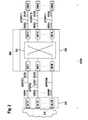
- FIG. 3 shows a preferred embodiment of the switching unit SU in detail.
- An optical filter OF1 is connectable to the optical interface OIF1.
- the optical filter OF1 splits the optical signals ODS1 and OUSL, which have different wavelengths.
- the optical downstream signal ODS1 is converted by an optical-electrical converter OEC1 into an electrical downstream signal EDS1, which is provided to an electrical splitter ES1.
- the splitter ES1 distributes the signal EDS1 onto L different incoming ports of an electrical switching unit ES1.
- Respective optical filters OF2, ..., OFM, optical-electrical converters OEC2, ..., OECM and electrical splitters ES2, ... , ESM distribute respective electrical downstream signals EDS2, ..., EDSM onto incoming ports of the electrical switching unit ES1.
- the electrical switching unit ES1 switches the electrical downstream signals EDS1, ..., EDSM onto outgoing ports of the electrical switching unit ES1, to which electrical combiners EC11, EC12, ..., EC1L are connected.
- the electrical combiners EC11, EC12, ..., EC1L forward the respective electrical downstream signals EDS1, EDS2 to transmitters TX11, TX12, ..., TX1L, which are preferably lasers.
- the transmitters TX11, TX12, ..., TX1L convert the electrical downstream signals EDS1, EDS2 back into the respective optical downstream signals ODS1, ODS2, which then are provided to optical filters OF11, OF12, ..., OF1L, which in turn are connectable to the optical interfaces OIF11, OIF12, ..., OIF1L.
- the optical filter OF11 splits the optical signals ODS2 and OUS1, which have different wavelengths.
- the optical upstream signal OUS1 is converted by an optical-electrical converter OEC11 into an electrical downstream signal EUS1, which is provided to an electrical splitter ES11.
- the splitter ES11 distributes the signal EUS1 onto M different incoming ports of an electrical switching unit ES2.
- Respective optical filters OF12, ..., OFL, optical-electrical converters OEC12, ... , OEC1L and electrical splitters ES12, ... , ES1L distribute respective electrical upstream signals EUS2, ..., EUSL onto incoming ports of the electrical switching unit ES2.
- the electrical switching unit ES2 switches the electrical upstream signals EUS1, ..., EUSL onto outgoing ports of the electrical switching unit ES2, to which electrical combiners EC1, EC2, ..., ECM are connected.
- the electrical combiners EC1, EC2, ..., ECM forward the respective electrical upstream signals EUS1, EUS2, EUSL to transmitters TX1, TX2, ..., TXM, which are preferably lasers.
- the transmitters TX1, TX2, ..., TX1M convert the electrical upstream signals EUS1, EUS2, EUSL back into the respective optical upstream signals OUS1, OUS2, OUSL, which then are provided to the optical filters OF1, OF2, ..., OFM, which in turn are connectable to the optical interfaces OIF1, OIF2, ..., OIF1M.
- optical-electrical converters OEC1, ... , OECM, OEC11, ... , OEC1 L perform a 2R-signal regeneration when converting optical signal to electrical signals.
- This 2R-signal regeneration includes amplitude regeneration and shape regeneration.
- the switching unit SU distributes the optical TDM downstream signals, by converting the optical TDM downstream signals into respective electrical TDM downstream signals and switching the electrical TDM downstream signals.
- the switched electrical TDM downstream signals are then converted back into optical TDM downstream signals.
- the switching unit SU maps the optical TDM upstream signals by converting the optical TDM upstream signals into respective electrical TDM upstream signals and to switch the electrical TDM upstream signals.
- the switched electrical TDM upstream signals are then converted back into optical TDM upstream signals.
- the configuration of the electrical switches is performed by a controlling unit not explicitly shown in the Figure 3 .
- This controlling unit may receive configuration instructions via an optical interface that is connectable via one of the optical interfaces to the access network.
- any switches shown in the Figure 2 , 3 and 4 may be provided through the use of dedicated hardware as well as hardware capable of executing software in association with appropriate software.
- the functions may be provided by a single dedicated processor, by a single shared processor, or by a plurality of individual processors, some of which may be shared.
- explicit use of the term "switch” should not be construed to refer exclusively to hardware capable of executing software, and may implicitly include, without limitation a application specific integrated circuit (ASIC) or a field programmable gate array (FPGA). Other hardware, conventional and/or custom, may also be included.
- any switches shown in the Figure 2 , 3 and 4 are conceptual only.
Landscapes
- Engineering & Computer Science (AREA)
- Computer Networks & Wireless Communication (AREA)
- Small-Scale Networks (AREA)
- Optical Communication System (AREA)
Abstract
Description
- The invention relates to a device and a method for connecting optical network elements in an optical access network
- It is known to provide to one or more subscribers a network connection to a telecommunications core network by means of an optical telecommunications access network. Such access networks are also known as passive optical networks (PON). The subscribers are preferably called customers or users.
- An interconnection between the access network and the core network or metro network is given at a so called central office. This interconnection is provided by a network sided access network termination unit, which is preferably called an optical line terminal (OLT). Within the access network, the OLT is connected via an optical fibre, preferably called optical feeder fibre, to a remote node located outside of the central office. Over the optical feeder fibre, the network sided access network termination unit transmits data in the downstream direction via an optical time division multiplex (TDM) signal to the remote node.
- At the remote node, the TDM signal transmitted in downstream direction is distributed onto a plurality of optical fibres of an optical distribution network, which is a part of the optical access network. This distribution may be performed in the optical domain by a device acting as an optical splitter device that splits the optical downstream TDM signal onto the optical fibres of the optical distribution network. To these optical fibres of the optical distribution network, either subscriber sided access network termination units, preferably called optical network units (ONU), are connected directly, or further branches of the optical distribution network are connected to these optical fibres of the optical distribution network. Each subscriber is connected to the access network at a subscriber connection point via a subscriber sided access network termination unit. To such a subscriber sided access network termination unit, the subscriber may connect customer premises equipment such as telephones, servers, multimedia devices or other communication devices.
- The subscriber sided access network termination units receive data from devices of the subscribers and transmit this data within timeslots of respective optical upstream TDM signals in the upstream direction towards the remote node. The optical upstream TDM signals are alternatively called optical upstream TDMA signals, wherein TDMA stands for time division multiple access. At the remote node, the upstream TDM signals received from the subscriber sided access network termination units are combined to a combined optical TDM signal which is then transmitted via the optical feeder fibre towards the network sided access network termination unit. Such a combination may be performed in the optical domain by a device acting as an optical combiner.
- An allocation of timeslots to the respective subscriber sided access network termination units for the downstream direction and the upstream direction is negotiated in advance between the subscriber sided access network termination units and the network sided access network termination unit during a so called ranging process.
- It is an objective, to improve the known devices for connecting optical network elements in an optical access network.
- Proposed is an optical device for connecting optical network elements in an optical access network.
- The device comprises a plurality of first optical interfaces adapted to receive respective optical TDM downstream signals via respective first optical point-to-point connections.
- The device comprises also a plurality of second optical interfaces adapted to receive respective optical TDM upstream signals via respective second optical point-to-point connections.
- The device comprises furthermore a switching unit, that is configurable to distribute the optical TDM downstream signals onto the second respective optical point-to-point connections
- such that a single of the second respective optical point-to-point connections is provided with only one of the optical TDM downstream signals,
- and such that at least one of the optical TDM downstream signals is distributed onto a plurality of the second respective optical point-to-point connections.
- The switching unit is furthermore configurable to map the optical TDM upstream signals onto the first optical point-to-point connections such that an optical TDM upstream signal is mapped onto the corresponding one of the first optical point-to-point connections from which it is provided with an optical TDM downstream signal.
- Furthermore, the switching unit is reconfigurable.
- In order to grasp the advantages of the proposed device, the following aspects have to be taken into consideration.
- Different optical TDM downstream signals may be received via the respective first optical point-to-point connections from different OLTs. Furthermore, different optical TDM upstream signals may be received at the respective second optical point-to-point connections from different ONUs. By distributing the optical TDM downstream signals onto the second respective optical point-to-point connections such that
- a single of the second respective optical point-to-point connections is provided with only one of the optical TDM downstream signals
- and such that at least one of the optical TDM downstream signals is distributed onto a plurality of the second respective optical point-to-point connections,
- In other words, the proposed device allows to connect a first OLT to a plurality of ONUs via a logical point-to-multipoint connection and, if desired, also a second OLT to another plurality of ONUs, or instead a single ONU, via a second logical point-to-multipoint connection. This corresponds to an assignment of multiple ONUs to one unique OLT. Since the switching unit is reconfigurable, it is possible change this assignment and to reassign a single ONU to another OLT. If desired, also multiple ONUs may be assigned to another OLT.
-
-
Figure 1 shows a remote node according to the prior art. -
Figure 2 shows an optical access network together with an embodiment of the proposed device. -
Figure 3 shows an embodiment of a switching unit in detail. -
Figure 1 shows an optical access network OAN as known from the prior art. At an interconnection of the optical access network OAN to a core network CAN, a network sided access network termination unit in the form of an optical line terminal OLT is placed. The OLT is preferably placed in a location called central office CO. The core network CN is alternatively a metro network. By the term central office is meant a location at which an interface or interconnection between the core network CN and the optical access network OAN is provided by means of hardware devices. - An OLT is a device that serves as the service provider's endpoint of the optical access network OAN. An OLT performs a conversion of electrical or optical signals received from or sent to the core network CN into optical signals received from or sent to subscriber sided access network termination units of the optical access network OAN. Preferably, the subscriber sided access network termination units are optical network units ONU or alternatively optical network terminals.
- The OLT is connected via an optical fibre OF to a remote node RN. The remote node contains a passive optical element OSC. The passive optical element OSC acts as an optical splitter for distributing an optical TDM signal sent in a downstream direction DS towards optical branches B1, B2, B3 of an optical distribution network ODN. Furthermore, the passive optical element OSC acts as an optical combiner for combining optical TDM signals received in an upstream direction US from the optical branches B1, B2, B3. The optical distribution network ODN is a subsegment of the optical access network OAN.
- Subscriber sided access network termination units ONU are connected to the ends of the optical branches B1, B2, B3. The optical branches B1, B2, B3 may contain further optical splitting and/or optical combining elements not explicitly shown in
Figure 1 . - The remote node RN as described above allows only to establish a fixed logical point-to-multipoint connection of a single OLT to a number of ONUs.
-
Figure 2 shows an optical access network OAN' together with a proposed optical device OD. The optical device OD is placed at a remote node RN' outside the central office CO. The proposed optical device OD itself may alternatively be called a remote node RN'. - The optical device OD contains a number of central office sided optical interfaces OIF1, OIF2, ..., OIFM, at which respective optical TDM downstream signals ODS1, ODS2, ... , ODSM are received via respective central office sided optical point-to-point connections OP2PC1, OP2PC2, ..., OP2PCM. The respective central office sided optical point-to-point connections OP2PC1, OP2PC2, ..., OP2PCM connect respective OLTs OLT1, OLT2, ...,OLTM with the optical device OD.
- A switching unit SU is connected to the central office sided optical interfaces OIF1, ..., OIFM as well as subscriber sided optical interfaces OIF11, OIF 12, ..., OIF1-. L. The subscriber sided optical interfaces OIF11, OIF 12, ..., OIF1L are adapted to receive respective optical TDM upstream signals OUS1, OUS2, ..., OUSL via respective subscriber sided optical point-to-point connections OP2PC11, OP2PC12, ..., OP2PC1 L. The respective optical point-to-point connections OP2PC11, OP2PC12, ..., OP2PC1L connect respective single ONUs ONU1, ONU2, ..., ONUL with the optical device OD.
- In the example shown in
Figure 2 , the switching unit SU distributes the optical TDM downstream signals ODS1, ODS2, ... , ODSM onto the subscriber sided optical point-to-point connections OP2PC11, OP2PC12, ..., OP2PC1 L. The downstream signal ODS1 is distributed onto the point-to-point connection OP2PC1L, while the downstream signal ODSM is distributed onto a point-to-point connection not explicitly shown inFigure 2 . The downstream signal ODS2 is distributed onto the point-to-point connection OP2PC11 and the point-to-point connection OP2PC12. - To summarize the above, the switching unit SU is configured such that it distributes the optical TDM downstream signals ODS1, ODS2, ... , ODSM onto the subscriber sided optical point-to-point connections OP2PC11, OP2PC12, ..., OP2PC1L, such that a single of the subscriber sided optical point-to-point connections OP2PC11, OP2PC12, ..., OP2PC1L is provided with only one of the optical TDM downstream signals ODS1, ODS2, ... , ODSM. Furthermore, the switching unit SU distributes the optical TDM downstream signals ODS1, ODS2, ... , ODSM onto the subscriber sided optical point-to-point connections OP2PC11, OP2PC12, ..., OP2PC1L, such that at least one of the optical TDM downstream signals ODS2 is distributed onto two or more of the subscriber sided optical point-to-point connections OP2PC11, OP2PC12.
- The subscriber sided point-to-point connections OP2PC11, OP2PC12, ..., OP2PC1L L are point-to-point connections in the sense that a subscriber sided network termination unit ONU1, ONU2, ..., ONUL is connected to the device OD via a separate, respective subscriber sided point-to-point connection OP2PC11, OP2PC12, ..., OP2PC1L. Furthermore, the subscriber sided point-to-point connections OP2PC11, OP2PC12, ..., OP2PC1L are point-to-point connections in the sense that a subscriber sided network termination unit ONU1, ONU2, ..., ONUL is connected to the device OD without a regeneration of optical signals taking place at the subscriber sided point-to-point connections OP2PC11, OP2PC12, ..., OP2PC1 L.
- Since the switching unit SU distributes the optical TDM downstream signal ODS1 received from the point-to-point connection OP2PC1 onto the point-to-point connection OP2PC1 L, it also maps the optical upstream signal OUSL received via the point-to-point connection OP2PC1L onto the point-to-point connection OP2PC1.
- Since the switching unit SU distributes the optical TDM downstream signal ODS2 received from the point-to-point connection OP2PC2 onto the point-to-point connections OP2PC11 and OP2PC12, it also maps the optical upstream signals OUS1 and OUS2 received via the point-to-point connections OP2PC11 and OP2PC12 onto the point-to-point connection OP2PC2.
- To summarize the above, the switching unit SU is configurable to map optical TDM upstream signals OUS1, OUS2 onto the network sided optical point-to-point connections OP2PC11, OP2PC12, such that an optical TDM upstream signal OUS1, OUS2 is mapped onto the corresponding one of the network sided optical point-to-point connections OP2PC11, OP2PC12, from which it is provided with an optical TDM downstream signal ODS2.
- By configuring the switching unit SU to a state as described above, at least one logical point-to-multipoint connection between an OLT OLT2 and a plurality of ONUs ONU1, ONU2 is established. Further logical point-to-multipoint connections may also be established. The switching unit SU of the device OD is reconfigurable to another state, in which also at least one logical point-to-multipoint connection is established between one OLT and a plurality of ONUs.
- As previously stated, the proposed device OD allows to connect a first OLT to a plurality of ONUs via a logical point-to-multipoint connection and preferably, if desired, also a second OLT to another plurality of ONUs via a second logical point-to-multipoint connection. This corresponds to an assignment of multiple ONUs to one respective unique OLT. Since the switching unit SU is reconfigurable, it is possible change this assignment and to reassign a single ONU to another OLT, or to reassign multiple ONUs to another OLTs. This may be desirable in the case, that different OLTs are owned by different providers and that an ONU of a customer, that desires to switch providers, should be re-connected to a different OLT of a different provider.
- Furthermore, a reconfiguration makes it possible to change an assignment of multiple ONUs from one OLT to one or more other OLTs. This may be desirable in the case that a first OLT is subject to a failure and that the ONUs assigned to the failing OLT should be re-assigned to one or more other faultless OLTs. This may alternatively also be desirable in the case that the point-to-point connection connecting one OLT is subject to a failure, such as a cable cut of the optical fibre, and that therefore the ONUs assigned to the OLT that is subject to the cut should be re-assigned to one or more other OLTs whose point-to-point connections are still working properly.
- Since an ONUs is uniquely assigned to a single OLT, the exchange of data signals provided by an OLT to on ONU or a group of ONUs is separated at the level of the physical layer, in name the optical layer. Thus, different providers may provide different OLTs, while each provider monitors the exchange of data between his specific OLT and the ONUs of customers that are subscribed to his logical part of the access network. Therefore, actions an observation of proper data exchange may be observed by a provider at this very own OLT.
- Furthermore, the flexibility of reconfiguring the switching unit for re-assigning one or more ONUs from one of the first point-to-point connections, leading to one OLT, to another of the first point-to-point connections, leading to another OLT, is an advantage in the case that the number of customers at a first point of time does not yet exceed the number of ONUs that may be handled by a single OLT. Assuming that a single OLT is able to handle a number of N ONUs but that at the first point of time the number of subscribed customers, each being provided with its own ONU, is smaller than N, then it would be sufficient to install in a central office only a single OLT at first. At a later point of time the number of customers wishing to subscribe at the provider may increase to a number greater than N, such that this can not be handled any more by just one single OLT. Therefore, at this later point of time a provider may provide a second OLT and connect new ONUs to this second OTL in order to serve also the new customers, for which a reconfiguration of the device connecting the OLTs and the ONUs may be desirable. By providing the new OLT not from the very beginning of the operation of the optical access network but only from the mentioned later point of time, the provisioning of the optical access network is less costly for the provider than when providing all OLTs from the very beginning.
- A remote node as described according to the prior art allows only to establish a fixed logical point-to-multipoint connection of a single OLT to a number of ONUs. Therefore, such a remote node does not achieve the advantages of the proposed device as outlined above.
-
Figure 3 shows a preferred embodiment of the switching unit SU in detail. - An optical filter OF1 is connectable to the optical interface OIF1. The optical filter OF1 splits the optical signals ODS1 and OUSL, which have different wavelengths. The optical downstream signal ODS1 is converted by an optical-electrical converter OEC1 into an electrical downstream signal EDS1, which is provided to an electrical splitter ES1. The splitter ES1 distributes the signal EDS1 onto L different incoming ports of an electrical switching unit ES1.
- Respective optical filters OF2, ..., OFM, optical-electrical converters OEC2, ..., OECM and electrical splitters ES2, ... , ESM distribute respective electrical downstream signals EDS2, ..., EDSM onto incoming ports of the electrical switching unit ES1. The electrical switching unit ES1 switches the electrical downstream signals EDS1, ..., EDSM onto outgoing ports of the electrical switching unit ES1, to which electrical combiners EC11, EC12, ..., EC1L are connected. The electrical combiners EC11, EC12, ..., EC1L forward the respective electrical downstream signals EDS1, EDS2 to transmitters TX11, TX12, ..., TX1L, which are preferably lasers. The transmitters TX11, TX12, ..., TX1L convert the electrical downstream signals EDS1, EDS2 back into the respective optical downstream signals ODS1, ODS2, which then are provided to optical filters OF11, OF12, ..., OF1L, which in turn are connectable to the optical interfaces OIF11, OIF12, ..., OIF1L.
- The optical filter OF11 splits the optical signals ODS2 and OUS1, which have different wavelengths. The optical upstream signal OUS1 is converted by an optical-electrical converter OEC11 into an electrical downstream signal EUS1, which is provided to an electrical splitter ES11. The splitter ES11 distributes the signal EUS1 onto M different incoming ports of an electrical switching unit ES2.
- Respective optical filters OF12, ..., OFL, optical-electrical converters OEC12, ... , OEC1L and electrical splitters ES12, ... , ES1L distribute respective electrical upstream signals EUS2, ..., EUSL onto incoming ports of the electrical switching unit ES2. The electrical switching unit ES2 switches the electrical upstream signals EUS1, ..., EUSL onto outgoing ports of the electrical switching unit ES2, to which electrical combiners EC1, EC2, ..., ECM are connected. The electrical combiners EC1, EC2, ..., ECM forward the respective electrical upstream signals EUS1, EUS2, EUSL to transmitters TX1, TX2, ..., TXM, which are preferably lasers. The transmitters TX1, TX2, ..., TX1M convert the electrical upstream signals EUS1, EUS2, EUSL back into the respective optical upstream signals OUS1, OUS2, OUSL, which then are provided to the optical filters OF1, OF2, ..., OFM, which in turn are connectable to the optical interfaces OIF1, OIF2, ..., OIF1M.
- The optical-electrical converters OEC1, ... , OECM, OEC11, ... , OEC1 L perform a 2R-signal regeneration when converting optical signal to electrical signals. This 2R-signal regeneration includes amplitude regeneration and shape regeneration.
- To summarize the above, the switching unit SU distributes the optical TDM downstream signals, by converting the optical TDM downstream signals into respective electrical TDM downstream signals and switching the electrical TDM downstream signals. The switched electrical TDM downstream signals are then converted back into optical TDM downstream signals. Furthermore, the switching unit SU maps the optical TDM upstream signals by converting the optical TDM upstream signals into respective electrical TDM upstream signals and to switch the electrical TDM upstream signals. The switched electrical TDM upstream signals are then converted back into optical TDM upstream signals.
- The configuration of the electrical switches is performed by a controlling unit not explicitly shown in the
Figure 3 . This controlling unit may receive configuration instructions via an optical interface that is connectable via one of the optical interfaces to the access network. - The description and drawings merely illustrate the principles of the invention. It will thus be appreciated that those skilled in the art will be able to devise various arrangements that, although not explicitly described or shown herein, embody the principles of the invention and are included within its spirit and scope. Furthermore, all examples recited herein are principally intended expressly to be only for pedagogical purposes to aid the reader in understanding the principles of the invention and the concepts contributed by the inventors to furthering the art, and are to be construed as being without limitation to such specifically recited examples and conditions. Moreover, all statements herein reciting principles, aspects, and embodiments of the invention, as well as specific examples thereof, are intended to encompass equivalents thereof.
- The functions of the various elements shown in the
Figure 2 ,3 and 4, may be provided through the use of dedicated hardware as well as hardware capable of executing software in association with appropriate software. When provided by a processor, the functions may be provided by a single dedicated processor, by a single shared processor, or by a plurality of individual processors, some of which may be shared. Moreover, explicit use of the term "switch" should not be construed to refer exclusively to hardware capable of executing software, and may implicitly include, without limitation a application specific integrated circuit (ASIC) or a field programmable gate array (FPGA). Other hardware, conventional and/or custom, may also be included. Similarly, any switches shown in theFigure 2 ,3 and 4, are conceptual only. Their function may be carried out through the operation of program logic, through dedicated logic, through the interaction of program control and dedicated logic, or even manually, the particular technique being selectable by the implementer as more specifically understood from the context. It should be appreciated by those skilled in the art that any block diagrams herein represent conceptual views of illustrative circuitry embodying the principles of the invention.
Claims (7)
- Optical device (OD) for connecting optical network elements in an optical access network (OAN),
comprising- a plurality of first optical interfaces (OIF1, ..., OIFM) adapted to receive respective optical time division multiplex (TDM) downstream signals (ODS1, ..., ODSM) via respective first optical point-to-point connections (OP2PC1, ..., OP2PCM),- a plurality of second optical interfaces (OIF11, ..., OIF1L) adapted to receive respective optical TDM upstream signals (OUS1, ..., OUSL) via respective second optical point-to-point connections (OP2PC11, ..., OP2PC1 L),- a switching unit (SU), configurableo to distribute said optical TDM downstream signals (ODS1, ..., ODSM) onto said second respective optical point-to-point connections (OP2PC11, ..., OP2PC1L) such that a single of said second respective optical point-to-point connections (OP2PC11, ..., OP2PC1 L) is provided with only one of said optical TDM downstream signals (ODS1, ..., ODSM) and such that at least one of said optical TDM downstream signals (ODS1, ..., ODSM) is distributed onto a plurality of said second respective optical point-to-point connections (OP2PC11, ..., OP2PC1 L),o and to map said optical TDM upstream signals (OUS1, ..., OUSL) onto said first optical point-to-point connections (OP2PC1, ..., OP2PCM) such that an optical TDM upstream signal (OUS1, ..., OUSL) is mapped onto the corresponding one of said first optical point-to-point connections (OP2PC1, ..., OP2PCM) from which it is provided with an optical TDM downstream signal,wherein said switching unit SU is reconfigurable. - Optical device (OD) according to claim 1,
wherein said switching unit SU is adapted- to distribute said optical TDM downstream signals (ODS1, ..., ODSM) in the electrical domain,- and to map said optical TDM upstream signals (OUS1, ..., OUSL) in the electrical domain. - Optical device (OD) according to claim 2,
wherein said switching unit SU is adapted- to distribute said optical TDM downstream signals (ODS1, ..., ODSM), by converting said optical TDM downstream signals (ODS1, ..., ODSM) into respective electrical TDM downstream signals (EDS1, ..., EDSM) and switching said electrical TDM downstream signals (EDS1, ..., EDSM),- and to map said optical TDM upstream signals (OUS1, ..., OUSL), by converting said optical TDM upstream signals (OUS1, ..., OUSL) into respective electrical TDM upstream signals (EUS1, ..., EUSL) and switching said electrical TDM upstream signals, - Method of connecting optical network elements in an optical access network (OAN'),
comprising- receiving a plurality of optical time division multiplex (TDM) downstream signals (ODS1, ..., ODSM) via respective first optical point-to-point connections (OP2PC1, ..., OP2PCM),- distributing said optical TDM downstream signals (ODS1, ..., ODSM) onto second respective optical point-to-point connections (OP2PC 11, ..., OP2PC1L) such that a single of said second respective optical point-to-point connections (OP2PC11, ..., OP2PC1L) is provided with only one of said optical TDM downstream signals (ODS1, ..., ODSM) and such that at least one of said optical TDM downstream signals (ODS1, ..., ODSM) is distributed onto a plurality of said second respective optical point-to-point connections (OP2PC11, ..., OP2PC1L),- receiving a plurality of optical TDM upstream signals (OUS1, ..., OUSL) via said second respective optical point-to-point connections (OP2PC 11, ..., OP2PC1L),- mapping said optical TDM upstream signals (OUS1, ..., OUSL) onto said first optical point-to-point connections(OP2PC1, ..., OP2PCM) such that an optical TDM upstream signal (OUS1, ..., OUSL) is mapped onto the corresponding one of said first optical point-to-point connections (OP2PC1, ..., OP2PCM) from which it is provided with an optical TDM downstream signal (ODS1, ..., ODSM). - Method according to claim 4,
wherein the step of distributing said optical TDM downstream signals (ODS1, ..., ODSM) is carried out in the electrical domain,
and wherein the step of mapping said optical TDM upstream signals (OUS1, ..., OUSL) is carried out in the electrical domain. - Method according to claim 5,
wherein said step of distributing said optical TDM downstream signals (ODS1, ..., ODSM) includes converting said optical TDM downstream signals (ODS1, ..., ODSM) into respective electrical TDM downstream signals (EDS1, ..., EDSM) and switching said electrical TDM downstream signals (EDS1, ..., EDSM),
and wherein said step of mapping said optical TDM upstream signals (OUS1, ..., OUSL) includes converting said optical TDM upstream signals (OUS1, ..., OUSL) into respective electrical TDM upstream signals (EUS1, ..., EUSL) and switching said electrical TDM upstream signals (EUS1, ..., EUSL). - Optical access network (OAN'),
comprising- a plurality of network sided access network termination units (OLT1, ...,OLTM),- a plurality of subscriber sided access network termination units (ONU1, ..., ONUL),- an optical device (OD) according to any of the claims 1 to 3,wherein said network sided access network termination units (OLT1, ...,OLTM), are connected to respective of said first optical interfaces of said optical device (OD), and wherein said subscriber sided access network termination units (ONU1, ..., ONUL) are connected to respective of said second optical interfaces of said optical device (OD).
Priority Applications (1)
| Application Number | Priority Date | Filing Date | Title |
|---|---|---|---|
| EP20110306006 EP2555542B1 (en) | 2011-08-02 | 2011-08-02 | Device for connecting optical network elements in an optical access network |
Applications Claiming Priority (1)
| Application Number | Priority Date | Filing Date | Title |
|---|---|---|---|
| EP20110306006 EP2555542B1 (en) | 2011-08-02 | 2011-08-02 | Device for connecting optical network elements in an optical access network |
Publications (2)
| Publication Number | Publication Date |
|---|---|
| EP2555542A1 true EP2555542A1 (en) | 2013-02-06 |
| EP2555542B1 EP2555542B1 (en) | 2014-03-05 |
Family
ID=44674661
Family Applications (1)
| Application Number | Title | Priority Date | Filing Date |
|---|---|---|---|
| EP20110306006 Active EP2555542B1 (en) | 2011-08-02 | 2011-08-02 | Device for connecting optical network elements in an optical access network |
Country Status (1)
| Country | Link |
|---|---|
| EP (1) | EP2555542B1 (en) |
Citations (3)
| Publication number | Priority date | Publication date | Assignee | Title |
|---|---|---|---|---|
| US20020071149A1 (en) * | 2000-12-12 | 2002-06-13 | Xu Dexiang John | Apparatus and method for protection of an asynchronous transfer mode passive optical network interface |
| US20090263122A1 (en) * | 2008-04-22 | 2009-10-22 | Roger Jonathan Helkey | Method and apparatus for network diagnostics in a passive optical network |
| US20100098407A1 (en) * | 2008-10-21 | 2010-04-22 | Teknovus, Inc. | Method and system for protection switching in ethernet passive optical networks |
-
2011
- 2011-08-02 EP EP20110306006 patent/EP2555542B1/en active Active
Patent Citations (3)
| Publication number | Priority date | Publication date | Assignee | Title |
|---|---|---|---|---|
| US20020071149A1 (en) * | 2000-12-12 | 2002-06-13 | Xu Dexiang John | Apparatus and method for protection of an asynchronous transfer mode passive optical network interface |
| US20090263122A1 (en) * | 2008-04-22 | 2009-10-22 | Roger Jonathan Helkey | Method and apparatus for network diagnostics in a passive optical network |
| US20100098407A1 (en) * | 2008-10-21 | 2010-04-22 | Teknovus, Inc. | Method and system for protection switching in ethernet passive optical networks |
Also Published As
| Publication number | Publication date |
|---|---|
| EP2555542B1 (en) | 2014-03-05 |
Similar Documents
| Publication | Publication Date | Title |
|---|---|---|
| US7715719B2 (en) | System and method for transmitting traffic in a plurality of passive optical networks | |
| US8442401B2 (en) | Method and device for fiber access physical layer unbundling using multiple uplink cards | |
| EP2564531B2 (en) | Optical access network | |
| US20050175344A1 (en) | System and apparatus for a carrier class WDM PON accommodating multiple services or protocols | |
| US9667376B2 (en) | Traffic-bearing entity identification in multiple-wavelength passive optical networks (PONs) | |
| WO2015112508A1 (en) | Optical line terminal communication method and device with data structure | |
| US20140186043A1 (en) | Passive optical network reach extender based on wavelength tunable optical module and method thereof | |
| WO2015066327A1 (en) | Hybrid fiber/cu distribution point with external onu-to-dsl conversion unit | |
| CN107071592B (en) | Communication method and communication system | |
| JP2013506329A (en) | Passive optical network apparatus and method | |
| JP2013143746A (en) | Optical signal relay device and optical communication network system | |
| JP6459588B2 (en) | Access control system, access control method, master station device, and slave station device | |
| CN101459473B (en) | Optical beam splitter, optical beam combiner and point-to-multipoint network system | |
| JP5704694B2 (en) | Optical access system | |
| EP2555542B1 (en) | Device for connecting optical network elements in an optical access network | |
| US9559802B1 (en) | Optical network remote node for G-PON and WDM-PON | |
| JP4809867B2 (en) | Optical access termination device | |
| CN105871498A (en) | Optical cross-connection scheduling apparatus, method and photo-electric hybrid cross system | |
| KR100889912B1 (en) | Optical subscriber network structure | |
| WO2013093833A2 (en) | Systems and methods for sharing of optical network terminals in passive optical network | |
| JP2014082560A (en) | Communication device and communication method | |
| CN103974150B (en) | A kind of light is the same as the method for transmitting signals in axle unit and Opto-electronic system | |
| CN101073211A (en) | System and apparatus for a carrier class WDM pon accommodating multiple services or protocols | |
| EP2779492B1 (en) | Access network and associated module | |
| KR100805549B1 (en) | Integrated service provision system in optical subscriber network |
Legal Events
| Date | Code | Title | Description |
|---|---|---|---|
| PUAI | Public reference made under article 153(3) epc to a published international application that has entered the european phase |
Free format text: ORIGINAL CODE: 0009012 |
|
| AK | Designated contracting states |
Kind code of ref document: A1 Designated state(s): AL AT BE BG CH CY CZ DE DK EE ES FI FR GB GR HR HU IE IS IT LI LT LU LV MC MK MT NL NO PL PT RO RS SE SI SK SM TR |
|
| AX | Request for extension of the european patent |
Extension state: BA ME |
|
| 17P | Request for examination filed |
Effective date: 20130806 |
|
| RBV | Designated contracting states (corrected) |
Designated state(s): AL AT BE BG CH CY CZ DE DK EE ES FI FR GB GR HR HU IE IS IT LI LT LU LV MC MK MT NL NO PL PT RO RS SE SI SK SM TR |
|
| GRAP | Despatch of communication of intention to grant a patent |
Free format text: ORIGINAL CODE: EPIDOSNIGR1 |
|
| 111Z | Information provided on other rights and legal means of execution |
Free format text: AL AT BE BG CH CY CZ DE DK EE ES FI FR GB GR HR HU IE IS IT LI LT LU LV MC MK MT NL NO PL PT RO RS SE SI SK SM TR Effective date: 20130410 |
|
| RIC1 | Information provided on ipc code assigned before grant |
Ipc: H04Q 11/00 20060101AFI20130911BHEP |
|
| INTG | Intention to grant announced |
Effective date: 20130926 |
|
| GRAS | Grant fee paid |
Free format text: ORIGINAL CODE: EPIDOSNIGR3 |
|
| GRAA | (expected) grant |
Free format text: ORIGINAL CODE: 0009210 |
|
| AK | Designated contracting states |
Kind code of ref document: B1 Designated state(s): AL AT BE BG CH CY CZ DE DK EE ES FI FR GB GR HR HU IE IS IT LI LT LU LV MC MK MT NL NO PL PT RO RS SE SI SK SM TR |
|
| REG | Reference to a national code |
Ref country code: GB Ref legal event code: FG4D |
|
| REG | Reference to a national code |
Ref country code: CH Ref legal event code: EP |
|
| REG | Reference to a national code |
Ref country code: AT Ref legal event code: REF Ref document number: 655547 Country of ref document: AT Kind code of ref document: T Effective date: 20140315 |
|
| REG | Reference to a national code |
Ref country code: IE Ref legal event code: FG4D |
|
| REG | Reference to a national code |
Ref country code: DE Ref legal event code: R096 Ref document number: 602011005253 Country of ref document: DE Effective date: 20140417 |
|
| REG | Reference to a national code |
Ref country code: AT Ref legal event code: MK05 Ref document number: 655547 Country of ref document: AT Kind code of ref document: T Effective date: 20140305 |
|
| REG | Reference to a national code |
Ref country code: NL Ref legal event code: VDEP Effective date: 20140305 |
|
| PG25 | Lapsed in a contracting state [announced via postgrant information from national office to epo] |
Ref country code: NO Free format text: LAPSE BECAUSE OF FAILURE TO SUBMIT A TRANSLATION OF THE DESCRIPTION OR TO PAY THE FEE WITHIN THE PRESCRIBED TIME-LIMIT Effective date: 20140605 Ref country code: LT Free format text: LAPSE BECAUSE OF FAILURE TO SUBMIT A TRANSLATION OF THE DESCRIPTION OR TO PAY THE FEE WITHIN THE PRESCRIBED TIME-LIMIT Effective date: 20140305 |
|
| REG | Reference to a national code |
Ref country code: CH Ref legal event code: PCOW Free format text: NEW ADDRESS: 148/152 ROUTE DE LA REINE, 92100 BOULOGNE-BILLANCOURT (FR) |
|
| REG | Reference to a national code |
Ref country code: FR Ref legal event code: GC Effective date: 20140602 |
|
| RAP2 | Party data changed (patent owner data changed or rights of a patent transferred) |
Owner name: ALCATEL LUCENT |
|
| REG | Reference to a national code |
Ref country code: LT Ref legal event code: MG4D |
|
| PG25 | Lapsed in a contracting state [announced via postgrant information from national office to epo] |
Ref country code: SE Free format text: LAPSE BECAUSE OF FAILURE TO SUBMIT A TRANSLATION OF THE DESCRIPTION OR TO PAY THE FEE WITHIN THE PRESCRIBED TIME-LIMIT Effective date: 20140305 Ref country code: CY Free format text: LAPSE BECAUSE OF FAILURE TO SUBMIT A TRANSLATION OF THE DESCRIPTION OR TO PAY THE FEE WITHIN THE PRESCRIBED TIME-LIMIT Effective date: 20140305 Ref country code: FI Free format text: LAPSE BECAUSE OF FAILURE TO SUBMIT A TRANSLATION OF THE DESCRIPTION OR TO PAY THE FEE WITHIN THE PRESCRIBED TIME-LIMIT Effective date: 20140305 Ref country code: AT Free format text: LAPSE BECAUSE OF FAILURE TO SUBMIT A TRANSLATION OF THE DESCRIPTION OR TO PAY THE FEE WITHIN THE PRESCRIBED TIME-LIMIT Effective date: 20140305 |
|
| PG25 | Lapsed in a contracting state [announced via postgrant information from national office to epo] |
Ref country code: LV Free format text: LAPSE BECAUSE OF FAILURE TO SUBMIT A TRANSLATION OF THE DESCRIPTION OR TO PAY THE FEE WITHIN THE PRESCRIBED TIME-LIMIT Effective date: 20140305 Ref country code: HR Free format text: LAPSE BECAUSE OF FAILURE TO SUBMIT A TRANSLATION OF THE DESCRIPTION OR TO PAY THE FEE WITHIN THE PRESCRIBED TIME-LIMIT Effective date: 20140305 Ref country code: RS Free format text: LAPSE BECAUSE OF FAILURE TO SUBMIT A TRANSLATION OF THE DESCRIPTION OR TO PAY THE FEE WITHIN THE PRESCRIBED TIME-LIMIT Effective date: 20140305 |
|
| PG25 | Lapsed in a contracting state [announced via postgrant information from national office to epo] |
Ref country code: BG Free format text: LAPSE BECAUSE OF FAILURE TO SUBMIT A TRANSLATION OF THE DESCRIPTION OR TO PAY THE FEE WITHIN THE PRESCRIBED TIME-LIMIT Effective date: 20140605 Ref country code: RO Free format text: LAPSE BECAUSE OF FAILURE TO SUBMIT A TRANSLATION OF THE DESCRIPTION OR TO PAY THE FEE WITHIN THE PRESCRIBED TIME-LIMIT Effective date: 20140305 Ref country code: NL Free format text: LAPSE BECAUSE OF FAILURE TO SUBMIT A TRANSLATION OF THE DESCRIPTION OR TO PAY THE FEE WITHIN THE PRESCRIBED TIME-LIMIT Effective date: 20140305 Ref country code: EE Free format text: LAPSE BECAUSE OF FAILURE TO SUBMIT A TRANSLATION OF THE DESCRIPTION OR TO PAY THE FEE WITHIN THE PRESCRIBED TIME-LIMIT Effective date: 20140305 Ref country code: BE Free format text: LAPSE BECAUSE OF FAILURE TO SUBMIT A TRANSLATION OF THE DESCRIPTION OR TO PAY THE FEE WITHIN THE PRESCRIBED TIME-LIMIT Effective date: 20140305 Ref country code: CZ Free format text: LAPSE BECAUSE OF FAILURE TO SUBMIT A TRANSLATION OF THE DESCRIPTION OR TO PAY THE FEE WITHIN THE PRESCRIBED TIME-LIMIT Effective date: 20140305 Ref country code: IS Free format text: LAPSE BECAUSE OF FAILURE TO SUBMIT A TRANSLATION OF THE DESCRIPTION OR TO PAY THE FEE WITHIN THE PRESCRIBED TIME-LIMIT Effective date: 20140705 |
|
| PG25 | Lapsed in a contracting state [announced via postgrant information from national office to epo] |
Ref country code: PL Free format text: LAPSE BECAUSE OF FAILURE TO SUBMIT A TRANSLATION OF THE DESCRIPTION OR TO PAY THE FEE WITHIN THE PRESCRIBED TIME-LIMIT Effective date: 20140305 Ref country code: ES Free format text: LAPSE BECAUSE OF FAILURE TO SUBMIT A TRANSLATION OF THE DESCRIPTION OR TO PAY THE FEE WITHIN THE PRESCRIBED TIME-LIMIT Effective date: 20140305 Ref country code: SK Free format text: LAPSE BECAUSE OF FAILURE TO SUBMIT A TRANSLATION OF THE DESCRIPTION OR TO PAY THE FEE WITHIN THE PRESCRIBED TIME-LIMIT Effective date: 20140305 |
|
| REG | Reference to a national code |
Ref country code: FR Ref legal event code: RG Effective date: 20141016 |
|
| REG | Reference to a national code |
Ref country code: DE Ref legal event code: R097 Ref document number: 602011005253 Country of ref document: DE |
|
| PG25 | Lapsed in a contracting state [announced via postgrant information from national office to epo] |
Ref country code: PT Free format text: LAPSE BECAUSE OF FAILURE TO SUBMIT A TRANSLATION OF THE DESCRIPTION OR TO PAY THE FEE WITHIN THE PRESCRIBED TIME-LIMIT Effective date: 20140707 |
|
| PLBE | No opposition filed within time limit |
Free format text: ORIGINAL CODE: 0009261 |
|
| STAA | Information on the status of an ep patent application or granted ep patent |
Free format text: STATUS: NO OPPOSITION FILED WITHIN TIME LIMIT |
|
| PG25 | Lapsed in a contracting state [announced via postgrant information from national office to epo] |
Ref country code: DK Free format text: LAPSE BECAUSE OF FAILURE TO SUBMIT A TRANSLATION OF THE DESCRIPTION OR TO PAY THE FEE WITHIN THE PRESCRIBED TIME-LIMIT Effective date: 20140305 |
|
| 26N | No opposition filed |
Effective date: 20141208 |
|
| REG | Reference to a national code |
Ref country code: DE Ref legal event code: R097 Ref document number: 602011005253 Country of ref document: DE Effective date: 20141208 |
|
| PG25 | Lapsed in a contracting state [announced via postgrant information from national office to epo] |
Ref country code: MC Free format text: LAPSE BECAUSE OF FAILURE TO SUBMIT A TRANSLATION OF THE DESCRIPTION OR TO PAY THE FEE WITHIN THE PRESCRIBED TIME-LIMIT Effective date: 20140305 Ref country code: LU Free format text: LAPSE BECAUSE OF FAILURE TO SUBMIT A TRANSLATION OF THE DESCRIPTION OR TO PAY THE FEE WITHIN THE PRESCRIBED TIME-LIMIT Effective date: 20140802 Ref country code: IT Free format text: LAPSE BECAUSE OF FAILURE TO SUBMIT A TRANSLATION OF THE DESCRIPTION OR TO PAY THE FEE WITHIN THE PRESCRIBED TIME-LIMIT Effective date: 20140305 |
|
| REG | Reference to a national code |
Ref country code: CH Ref legal event code: PL |
|
| PG25 | Lapsed in a contracting state [announced via postgrant information from national office to epo] |
Ref country code: LI Free format text: LAPSE BECAUSE OF NON-PAYMENT OF DUE FEES Effective date: 20140831 Ref country code: CH Free format text: LAPSE BECAUSE OF NON-PAYMENT OF DUE FEES Effective date: 20140831 |
|
| REG | Reference to a national code |
Ref country code: IE Ref legal event code: MM4A |
|
| PG25 | Lapsed in a contracting state [announced via postgrant information from national office to epo] |
Ref country code: SI Free format text: LAPSE BECAUSE OF FAILURE TO SUBMIT A TRANSLATION OF THE DESCRIPTION OR TO PAY THE FEE WITHIN THE PRESCRIBED TIME-LIMIT Effective date: 20140305 |
|
| REG | Reference to a national code |
Ref country code: FR Ref legal event code: PLFP Year of fee payment: 5 |
|
| PG25 | Lapsed in a contracting state [announced via postgrant information from national office to epo] |
Ref country code: IE Free format text: LAPSE BECAUSE OF NON-PAYMENT OF DUE FEES Effective date: 20140802 |
|
| PG25 | Lapsed in a contracting state [announced via postgrant information from national office to epo] |
Ref country code: SM Free format text: LAPSE BECAUSE OF FAILURE TO SUBMIT A TRANSLATION OF THE DESCRIPTION OR TO PAY THE FEE WITHIN THE PRESCRIBED TIME-LIMIT Effective date: 20140305 |
|
| PG25 | Lapsed in a contracting state [announced via postgrant information from national office to epo] |
Ref country code: MT Free format text: LAPSE BECAUSE OF FAILURE TO SUBMIT A TRANSLATION OF THE DESCRIPTION OR TO PAY THE FEE WITHIN THE PRESCRIBED TIME-LIMIT Effective date: 20140305 Ref country code: GR Free format text: LAPSE BECAUSE OF FAILURE TO SUBMIT A TRANSLATION OF THE DESCRIPTION OR TO PAY THE FEE WITHIN THE PRESCRIBED TIME-LIMIT Effective date: 20140606 |
|
| PG25 | Lapsed in a contracting state [announced via postgrant information from national office to epo] |
Ref country code: HU Free format text: LAPSE BECAUSE OF FAILURE TO SUBMIT A TRANSLATION OF THE DESCRIPTION OR TO PAY THE FEE WITHIN THE PRESCRIBED TIME-LIMIT; INVALID AB INITIO Effective date: 20110802 Ref country code: TR Free format text: LAPSE BECAUSE OF FAILURE TO SUBMIT A TRANSLATION OF THE DESCRIPTION OR TO PAY THE FEE WITHIN THE PRESCRIBED TIME-LIMIT Effective date: 20140305 |
|
| REG | Reference to a national code |
Ref country code: FR Ref legal event code: PLFP Year of fee payment: 6 |
|
| REG | Reference to a national code |
Ref country code: FR Ref legal event code: PLFP Year of fee payment: 7 |
|
| PG25 | Lapsed in a contracting state [announced via postgrant information from national office to epo] |
Ref country code: MK Free format text: LAPSE BECAUSE OF FAILURE TO SUBMIT A TRANSLATION OF THE DESCRIPTION OR TO PAY THE FEE WITHIN THE PRESCRIBED TIME-LIMIT Effective date: 20140305 |
|
| REG | Reference to a national code |
Ref country code: FR Ref legal event code: PLFP Year of fee payment: 8 |
|
| PG25 | Lapsed in a contracting state [announced via postgrant information from national office to epo] |
Ref country code: AL Free format text: LAPSE BECAUSE OF FAILURE TO SUBMIT A TRANSLATION OF THE DESCRIPTION OR TO PAY THE FEE WITHIN THE PRESCRIBED TIME-LIMIT Effective date: 20140305 |
|
| PGFP | Annual fee paid to national office [announced via postgrant information from national office to epo] |
Ref country code: FR Payment date: 20190711 Year of fee payment: 9 |
|
| PG25 | Lapsed in a contracting state [announced via postgrant information from national office to epo] |
Ref country code: FR Free format text: LAPSE BECAUSE OF NON-PAYMENT OF DUE FEES Effective date: 20200831 |
|
| PGFP | Annual fee paid to national office [announced via postgrant information from national office to epo] |
Ref country code: DE Payment date: 20250702 Year of fee payment: 15 |
|
| PGFP | Annual fee paid to national office [announced via postgrant information from national office to epo] |
Ref country code: GB Payment date: 20250703 Year of fee payment: 15 |