EP2555186A2 - Encoding method and device, and decoding method and device - Google Patents
Encoding method and device, and decoding method and device Download PDFInfo
- Publication number
- EP2555186A2 EP2555186A2 EP11763047A EP11763047A EP2555186A2 EP 2555186 A2 EP2555186 A2 EP 2555186A2 EP 11763047 A EP11763047 A EP 11763047A EP 11763047 A EP11763047 A EP 11763047A EP 2555186 A2 EP2555186 A2 EP 2555186A2
- Authority
- EP
- European Patent Office
- Prior art keywords
- mdct
- coefficients
- residual
- pulse
- index
- Prior art date
- Legal status (The legal status is an assumption and is not a legal conclusion. Google has not performed a legal analysis and makes no representation as to the accuracy of the status listed.)
- Withdrawn
Links
Images


Classifications
-
- G—PHYSICS
- G10—MUSICAL INSTRUMENTS; ACOUSTICS
- G10L—SPEECH ANALYSIS TECHNIQUES OR SPEECH SYNTHESIS; SPEECH RECOGNITION; SPEECH OR VOICE PROCESSING TECHNIQUES; SPEECH OR AUDIO CODING OR DECODING
- G10L19/00—Speech or audio signals analysis-synthesis techniques for redundancy reduction, e.g. in vocoders; Coding or decoding of speech or audio signals, using source filter models or psychoacoustic analysis
- G10L19/02—Speech or audio signals analysis-synthesis techniques for redundancy reduction, e.g. in vocoders; Coding or decoding of speech or audio signals, using source filter models or psychoacoustic analysis using spectral analysis, e.g. transform vocoders or subband vocoders
- G10L19/0212—Speech or audio signals analysis-synthesis techniques for redundancy reduction, e.g. in vocoders; Coding or decoding of speech or audio signals, using source filter models or psychoacoustic analysis using spectral analysis, e.g. transform vocoders or subband vocoders using orthogonal transformation
-
- G—PHYSICS
- G10—MUSICAL INSTRUMENTS; ACOUSTICS
- G10L—SPEECH ANALYSIS TECHNIQUES OR SPEECH SYNTHESIS; SPEECH RECOGNITION; SPEECH OR VOICE PROCESSING TECHNIQUES; SPEECH OR AUDIO CODING OR DECODING
- G10L19/00—Speech or audio signals analysis-synthesis techniques for redundancy reduction, e.g. in vocoders; Coding or decoding of speech or audio signals, using source filter models or psychoacoustic analysis
- G10L19/0017—Lossless audio signal coding; Perfect reconstruction of coded audio signal by transmission of coding error
-
- G—PHYSICS
- G10—MUSICAL INSTRUMENTS; ACOUSTICS
- G10L—SPEECH ANALYSIS TECHNIQUES OR SPEECH SYNTHESIS; SPEECH RECOGNITION; SPEECH OR VOICE PROCESSING TECHNIQUES; SPEECH OR AUDIO CODING OR DECODING
- G10L19/00—Speech or audio signals analysis-synthesis techniques for redundancy reduction, e.g. in vocoders; Coding or decoding of speech or audio signals, using source filter models or psychoacoustic analysis
- G10L19/04—Speech or audio signals analysis-synthesis techniques for redundancy reduction, e.g. in vocoders; Coding or decoding of speech or audio signals, using source filter models or psychoacoustic analysis using predictive techniques
- G10L19/16—Vocoder architecture
- G10L19/18—Vocoders using multiple modes
- G10L19/24—Variable rate codecs, e.g. for generating different qualities using a scalable representation such as hierarchical encoding or layered encoding
-
- G—PHYSICS
- G10—MUSICAL INSTRUMENTS; ACOUSTICS
- G10L—SPEECH ANALYSIS TECHNIQUES OR SPEECH SYNTHESIS; SPEECH RECOGNITION; SPEECH OR VOICE PROCESSING TECHNIQUES; SPEECH OR AUDIO CODING OR DECODING
- G10L19/00—Speech or audio signals analysis-synthesis techniques for redundancy reduction, e.g. in vocoders; Coding or decoding of speech or audio signals, using source filter models or psychoacoustic analysis
- G10L19/02—Speech or audio signals analysis-synthesis techniques for redundancy reduction, e.g. in vocoders; Coding or decoding of speech or audio signals, using source filter models or psychoacoustic analysis using spectral analysis, e.g. transform vocoders or subband vocoders
- G10L19/032—Quantisation or dequantisation of spectral components
Definitions
- the present invention relates to an encoding method and apparatus and a decoding method and apparatus, and particularly relates to encoding/decoding method and apparatus using modified discrete cosine transform (MDCT).
- MDCT modified discrete cosine transform
- VoIP voice over IP
- a data rate of, for example, 64kbps when they are sampled at 8kHz and each sample is encoded with 8 bits
- the speech can be transmitted in a lower data rate if a signal analysis technique and a proper coding technique are used.
- a waveform coding, a code-excited linear prediction (CELP) coding, and a transform coding method are widely used for speech and audio compression.
- the waveform coding scheme is very simple and encodes amplitude of each sample itself or a difference between each sample and a previous sample in a predetermined number of bits, but a higher bit rate is required.
- the CELP coding scheme is based on a speech production model, and models the speech with a linear prediction filter and an excitation signal. It can compress the speech in a relatively lower rate, but its performance on the audio signal is deteriorated.
- the transform coding scheme transforms time domain speech signals into frequency domain signals, and then encodes transformed coefficients corresponding to each frequency component. Typically, it can encode each frequency component using the auditory characteristics of humans.
- a speech codec for the communication has evolved from narrowband coding of a conventional telephone bandwidth to wideband or super wideband coding capable of providing a better naturalness and clarity.
- a multi-rate codec supporting to multiple bit rates in a single codec is widely used to accommodate a variety of network environments.
- an embedded variable bit rate codec has been developed to provide bandwidth scalability for adopting signals with various bandwidths and bit-rate scalability in embedded manner.
- the embedded variable bit rate codec is configured such that a bit stream of a higher bit rate contains a bit stream of a lower bit rate. It usually adopts a hierarchical coding scheme. As the signal bandwidth increases, a quality of codec for audio signal such as music is also considered as an important factor.
- a hybrid coding scheme where overall signal bandwidth is divided into two subband signals such that the waveform coding scheme or the CELP coding scheme are applied to lower band signal and the transform coding scheme is applied to higher band signal, is used.
- the transform coding scheme is widely used in a speech codec for communication that supports the wideband or super wideband, as well as the conventional audio codec.
- time domain signal is required to be transformed into frequency domain signal.
- the Modified Discrete Cosine Transform is used.
- the quality of transform codec suffers from quantization errors of the MDCT coefficients caused by the limited bit rate of the codec.
- a method for reducing the MDCT quantization error by adding an enhancement layer with a relatively low bit rate can be used.
- the overall quantization performance of the core layer and the enhancement layer is determined by the MDCT quantization performance of the core layer.
- fewer bits are allocated to the MDCT coefficient such that the large quantization error cannot be effectively compensated.
- aspects of the present invention provide an encoding/decoding method and apparatus for effectively compensating a quantization error.
- an MDCT encoding method of an encoder includes transforming an input signal to generate first modified discrete cosine transform (MDCT) coefficients by, quantizing the first MDCT coefficients to generate MDCT indices, dequantizing the MDCT indices to generate second MDCT coefficients, computing MDCT residual coefficients using differences between the first MDCT coefficients and the second MDCT coefficients, encoding the MDCT residual coefficients to generate a residual index by, and generating gain indices corresponding to gains of the first MDCT coefficients from the first MDCT coefficients and the second MDCT coefficients.
- MDCT modified discrete cosine transform
- the encoding method may further include multiplex the MDCT indices, the residual index, and the gain indices to generate a bit stream.
- Generating the residual index may include selecting an index of a sub-band with a largest energy of MDCT residual coefficients among a plurality of sub-bands, and generating a sub-band index by encoding the selected index.
- the residual index may include the sub-band index.
- u j and l j are a lower boundary index and an upper boundary index of the j-th sub-band, respectively, and E(k) is a k-th MDCT residual coefficient.
- Generating the residual index may further include encoding MDCT residual coefficients of the selected sub-band.
- Encoding the MDCT residual coefficients may further include configuring a plurality of tracks for MDCT residual coefficients of the selected sub-band, selecting a pulse corresponding to a predetermined number of MDCT residual coefficients having a largest absolute value, among MDCT residual coefficients corresponding to possible positions in each track, and coding the pulse.
- the residual index may further include a coded value of the pulse.
- Coding the pulse may include coding a position of the pulse, coding the sign of the pulse, and coding the amplitude of the pulse.
- the coded value of the pulse may include a coded value of the position, a coded value of the sign, and a coded value of the amplitude.
- the position may be a position that is relative to a lower boundary index of the selected sub-band.
- Encoding the MDCT residual coefficients may include computing a root mean square (RMS) value of the MDCT residual coefficients of the selected sub-band, and quantizing the RMS value to generate an RMS index.
- the residual index may further include the RMS index.
- Encoding the amplitude of the pulse may include dequantizing the RMS index to generate a quantized RMS value, and coding the amplitude of the pulse using the amplitude of the pulse divided by the quantized RMS value.
- Generating the gain indices may include computing exponents as logarithms of magnitudes of the second MDCT coefficients at positions excluding the position of the pulse, setting an exponent to a minimum exponent magnitude at the position of the pulse, and allocating bits for the gain indices based on the exponents.
- Generating the gain indices may further include determining the gain indices from the allocated bits, the first MDCT coefficients, and the second MDCT coefficients.
- the gain index may be determined as i for maximizing - 2 ⁇ g i m ⁇ X k ⁇ X ⁇ k + g i m 2 ⁇ X ⁇ k .
- g i m is an i-th codeword of a codebook corresponding to m bits
- i is an integer within a range of 0 to (2 m -1)
- X ( k) is a k-th first MDCT residual coefficient
- X ⁇ (k) is a k-th second MDCT residual coefficient.
- an MDCT decoding method of a decoder includes receiving MDCT indices, a residual index, and gain indices, dequantizing the MDCT indices to generate first MDCT coefficients, decoding the residual index to recover MDCT residual coefficients, recovering gains from the gain indices using a position of a pulse corresponding to the MDCT residual coefficients and the first MDCT coefficients, compensating gains of the first MDCT coefficients with the recovered gains to generate second MDCT coefficients, and compensating residuals of the second MDCT coefficients with the MDCT residual coefficients.
- Compensating the residuals may include adding the MDCT residual coefficients to the second MDCT coefficients.
- the MDCT residual coefficients may have a value of 0 at positions excluding the position of the pulse.
- the residual index may include a sub-band index
- recovering the MDCT residual coefficients may include determining a sub-band of the MDCT residual coefficients by decoding the sub-band index.
- the residual index may include a coded value of the position of the pulse, a coded value of the sign of the pulse, and a coded value of the amplitude of the pulse.
- Recovering the MDCT residual coefficients may include decoding the coded value of the amplitude of the pulse to recover the amplitude of the pulse, decoding the coded value of the position of the pulse to recover the position of the pulse, decoding the coded value of the sign of the pulse to recover the sign of the pulse, and recovering the MDCT residual coefficients based on the position, sign, and amplitude of the pulse.
- the residual index may further include a root mean square (RMS) index.
- Recovering the amplitude of the pulse may include generating a quantized RMS value from the RMS index, and multiplying the decoded amplitude of the pulse by the quantized RMS value to recover the amplitude of the pulse.
- RMS root mean square
- Recovering the gains may include computing exponents as logarithms of magnitudes of the first MDCT coefficients at positions excluding the position of the pulse, setting an exponent to a minimum exponent magnitude at the position of the pulse, and generating a bit allocation table by allocating bits to the gain indices based on the exponents.
- Recovering the gains may further include recovering the gains from the gain indices using the bit allocation table.
- the decoding method may further include recovering a signal by transforming MDCT coefficients, which are generated by compensating the residuals of the second MDCT coefficients, by an inverse MDCT.
- an MDCT encoding apparatus including an MDCT, an MDCT quantizer, an enhancement layer encoder, and a multiplexer.
- the MDCT transforms an input signal to generate first MDCT coefficients
- the MDCT quantizer quantizes the first MDCT coefficients to generate MDCT indices.
- the enhancement layer encoder dequantizes the MDCT indices to generate second MDCT coefficients, encoding MDCT residual coefficients corresponding to differences between the first MDCT coefficients and the second MDCT coefficients to generate a residual index, and generates gain indices corresponding to gains of the first MDCT coefficients from the first MDCT coefficients and the second MDCT coefficients.
- the multiplexer multiplexes the MDCT indices, the residual index, and the gain indices to generate a bit stream.
- an MDCT decoding apparatus including a demultiplexer, an MDCT dequantizer, and an enhancement layer decoder.
- the demultiplexer demultiplexes a received bit stream to output MDCT indices, a residual index, and gain indices, and the MDCT dequantizer dequantizes the MDCT indices to generate first MDCT coefficients.
- the enhancement layer decoder decodes the residual index to recover MDCT residual coefficients, recovers gains from the gain indices using a position of a pulse corresponding to the MDCT residual coefficients and the first MDCT coefficients, compensates gains of the first MDCT coefficients with the recovered gains to generate second MDCT coefficients, and compensates residuals of the second MDCT coefficients with the MDCT residual coefficients.
- a combination of gain compensation scheme and residual compensation scheme can mitigate degradation of sound quality which may be resulted from a spectrum distortion caused by inconsistency between bit allocation in the gain compensation scheme and actual errors.
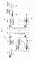
- FIG. 1 is a block diagram showing one example of a hierarchical MDCT quantization system
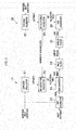
- FIG. 2 is a block diagram showing a gain compensation encoder and a gain compensation decoder shown in FIG. 1
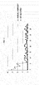
- FIG. 3 is a drawing showing performance of the MDCT quantization system shown in FIG. 1 .
- the hierarchical MDCT quantization system includes an encoder 110 for encoding input signal to generate a bit stream, and a decoder 120 for decoding the bit stream to generate a reconstructed signal.
- the encoder 110 includes an MDCT 111, a core layer MDCT quantizer 112, an enhancement layer encoder 113, and a multiplexer 114.
- the enhancement layer encoder 113 includes a local MDCT dequantizer 115 and a gain compensation encoder 116.
- the MDCT 111 transforms the input signal into MDCT coefficients as in Equation 1.
- N is a number of samples in a frame corresponding to processing unit of time domain input signal in a block-by-block basis
- w(n) is a window function
- x(n) is the input signal
- X(k) is the MDCT coefficient
- n is a time domain index
- k is a frequency domain index.
- the core layer MDCT quantizer 112 quantizes the MDCT coefficients to generate quantized MDCT indices.
- the core layer MDCT quantizer 112 may use various traditional quantization schemes such as the shape-gain vector quantization (VQ), the lattice VQ, the spherical VQ, and the algebraic VQ etc.
- the local MDCT dequantizer 115 outputs quantized MDCT coefficients from the MDCT indices by dequantization.
- the gain compensation encoder 116 calculates gains between unquantized MDCT coefficients and the quantized MDCT coefficients, and quantizes the gains to generate gain indices.
- the multiplexer 114 multiplexes the MDCT indices and the gain indices to output the bit stream.
- the decoder 120 includes a demultiplexer 121, a core layer MDCT dequantizer 122, an enhancement layer decoder 123, and an inverse MDCT (IMDCT) 124.
- the enhancement layer decoder 123 includes a gain compensation decoder 125 and a gain compensator 126.
- the demultiplexer 121 demultiplexes the received bit stream to output the MDCT indices and the gain indices.
- the core layer MDCT dequantizer 122 outputs quantized MDCT coefficients from the MDCT indices by dequantization.
- the gain compensation decoder 125 decodes the gain indices to output quantized gains.
- the gain compensator 126 scales the quantized MDCT coefficients by the quantized gains to output gain-compensated MDCT coefficients.
- the gain-compensated MDCT coefficients can be obtained as in Equation 2.
- X ⁇ (k) and X ⁇ gc ( k ) are the quantized MDCT coefficients and the gain-compensated MDCT coefficients, respectively, and ⁇ ( k ) is the quantized gain.
- the IMDCT 124 inversely transforms the gain-compensated MDCT coefficients into intermediate signal in time domain as expressed in Equation 3.
- the gain compensation encoder 116 includes an exponent calculator 211, a bit allocation calculator 212, a gain calculator 213, a gain quantizer 214, and a multiplexer 215.
- the exponent calculator 211 calculates an exponent by dividing an absolute value of each quantized MDCT coefficient by a predetermined step. For example, assuming that the step is set to a logarithmic unit with a base of 2, the exponent calculator 211 may calculate the exponent as the logarithm of the quantized MDCT coefficient. Accordingly, the calculated exponent is exponentially proportional to the absolute value of the quantized MDCT coefficient.
- is an absolute value operation
- ⁇ is a rounding operation
- MIN_EXP and MAX_EXP are a minimum and a maximum exponent magnitude, respectively.
- the bit allocation calculator 212 dynamically calculates the number of bits for gain quantization of each MDCT coefficient, using exponent of all the MDCT coefficients in a frame and the predetermined number of available bits, thereby outputting a bit allocation table.
- the bit allocation table stores the number of bits allocated to compensate gain of each MDCT coefficient within the available bit budget.
- the bit allocation calculator 212 may restrict the minimum and the maximum number of gain bits allowable for each MDCT coefficient, as in Equation 5.
- MIN_BITS and MAX_BITS are the minimum and the maximum number of gain bits, respectively.
- B enh is the total number of bits allocated to the enhancement layer.
- the gain calculator 213 calculates a gain between the unquantized MDCT coefficient and the quantized MDCT coefficient, and outputs the gain for each MDCT coefficient.
- the gain calculator 213 may calculate the gain for minimizing error as in Equation 6.
- Err(k) is the error for k-th MDCT coefficient
- g(k) is the gain for k-th MDCT coefficient.
- the gain quantizer 214 quantizes the gains using the number of quantized bits corresponding to each MDCT coefficient in the bit allocation table, and outputs gain indices.
- the gain calculator 213 and the gain quantizer 214 may determine the gain indices by searching the gain quantization codebook using the unquantized MDCT coefficient and the quantized MDCT coefficient.
- the gain index may be given as in Equation 7.
- I opt k argmax g i m ⁇ C g m
- i 0 , ... , 2 m - 1 - 2 ⁇ g i m ⁇ X k ⁇ X ⁇ k + g i m 2 ⁇ X ⁇ k
- C g m is a codebook corresponding to m bits and has 2 m codewords.
- g i m is the i-th codeword of the m-bit codebook
- I opt (k) is the best gain index corresponding to the k-th MDCT coefficient.
- the multiplexer 215 multiplexes the gain index for each MDCT coefficient to output a gain bit stream.
- the gain compensation decoder 125 includes a demultiplexer 221, an exponent calculator 222, a bit allocation calculator 223, and a gain dequantizer 224.
- the exponent calculator 222 and the bit allocation calculator 223 perform the same operations as the exponent calculator 211 and the bit allocation calculator 212 of the gain correction encoder 116.
- the demultiplexer 221 demultiplexes the gain bit stream to extract the gain indices for the MDCT coefficients referring to the bit allocation table.
- the gain dequantizer 224 recovers the quantized gain for each MDCT coefficient using each gain index and the bit allocation table.
- a gain compensation method of frequency domain coefficients can provide relatively simple and excellent performance.
- the number of bits that are dynamically allocated to each MDCT coefficient depends only on the absolute value of the quantized MDCT coefficient, the overall quantization performance of the combination of core layer and enhancement layer may be deteriorated if the performance of the core layer MDCT quantizer 112 is poor. That is, when the core layer MDCT quantizer results in a large quantization error in a certain MDCT coefficient and the magnitude of the quantized MDCT coefficient is less than the magnitude of other coefficients, a dynamic bit allocator may allocate fewer bits to the MDCT coefficient. As a result, the large quantization error of the core layer cannot be effectively compensated.
- FIG. 3 a bit allocation table and magnitudes of MDCT residual coefficients, which are calculated by performing a method of FIG. 1 and FIG. 2 on a input speech frame, are illustrated.
- a frame length N is 40, and the minimum and the maximum number of bits per MDCT coefficient are 0 and 3, respectively.
- the magnitudes of the first six MDCT residual coefficients are significantly greater than the remaining residual coefficients, it can be noted that no bits are allocated to the first six MDCT residual coefficients.
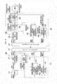
- FIG. 4 is a block diagram of a hierarchical MDCT quantization system according to an embodiment of the present invention.
- the hierarchical MDCT quantization system includes a speech and audio encoder 410 and a decoder 420 that use a hierarchical MDCT quantization scheme.
- the encoder 410 includes an MDCT 411, a core layer MDCT quantizer 412, an enhancement layer encoder 413, and a multiplexer 414.
- the enhancement layer encoder 413 includes a local MDCT dequantizer 415, a gain compensation encoder 416, and a residual compensation encoder 417.
- the MDCT 411 transforms an input signal into MDCT coefficients by the MDCT.
- the input signal is a full band speech and/or audio signal with a whole band, a signal with only a part of whole band at a split band codec, or a residual signal of a scalable codec.
- the core layer MDCT quantizer 412 quantizes the MDCT coefficients to output MDCT indices.
- the local MDCT dequantizer 415 outputs quantized MDCT coefficients from the MDCT indices by dequantization.
- the MDCT 411, the core layer MDCT quantizer 412, and the local MDCT dequantizer 415 may operate in the same way as the MDCT 111, the core layer MDCT quantizer 112, and the local MDCT dequantizer 115 described in FIG. 1 .
- Equation 8 the total number of bits allocated to the enhancement layer is divided into two parts, which are allocated to gain compensation encoding of the gain compensation encoder 416 and residual compensation encoding of the residual compensation encoder 417.
- B enh B gc + B ec
- B enh is the entire number of bits allocated to the enhancement layer
- B gc and B ec are the number of bits allocated to the gain compensation encoder 416 and the number of bits allocated to the residual compensation encoder 417, respectively.
- the number of bits B enh allocated to the enhancement layer may be equal to the number of available bits of FIG. 2 .
- the residual compensation encoder 417 calculates MDCT residual coefficients from the unquantized MDCT coefficients and the quantized MDCT coefficients. For example, the MDCT residual coefficients are computed by subtracting the quantized MDCT coefficient from the unquantized MDCT coefficient and.
- the residual compensation encoder 417 selects a predetermined number of MDCT residual coefficients among the entire MDCT residual coefficients, and quantizes the selected MDCT residual coefficients to output residual indices. Further, the residual compensation encoder 417 transfers position information of the selected MDCT residual coefficients, i.e., pulse position information, to an exponent calculator 416a of the gain compensation encoder 416.
- the gain compensation encoder 416 calculates gains based on unquantized MDCT coefficients, the quantized MDCT coefficients, and the pulse position information, and then quantizes each gain to output a gain index.
- the exponent calculator 416a of the gain compensation encoder 416 sets exponents of the MDCT coefficients corresponding to the pulse position information from the residual compensation encoder 417 to a minimum value of MIN_EXP, and calculates exponents of the remaining MDCT coefficients as described with reference to FIG. 1 and FIG. 2 .
- the gain compensation encoder 416 may calculate the exponents by changing the number of available bits from B enh to B gc in the exponent calculating procedure of the exponent calculator 211 shown in FIG. 2 .
- the multiplexer 414 multiplexes the MDCT indices, the gain indices, and the residual indices to output a bit stream.
- the decoder 420 includes a demultiplexer 421, a core layer MDCT dequantizer 422, an enhancement layer decoder 423, and an IMDCT 424.
- the enhancement layer decoder 423 includes a gain compensation decoder 425, a gain compensator 426, a residual compensation decoder 427, and an error compensator 428.
- the demultiplexer 421 demultiplexes the received bit stream to output the MDCT indices, the gain indices, and the residual indices.
- the core layer MDCT dequantizer 422 dequantizes the MDCT indices to output the quantized MDCT coefficients.
- the gain compensator 426 scales the quantized MDCT coefficients by the quantized gains to output gain-compensated MDCT coefficients.
- the IMDCT 424 inversely transforms the reconstructed MDCT coefficients to a reconstructed signal.
- the core layer MDCT dequantizer 422, the gain compensator 426, and the IMDCT 424 may operate in the same way as the core layer MDCT dequantizer 122, the gain compensator 126, and the IMDCT 124 described with reference to FIG. 1 .
- the residual compensation decoder 427 decodes the residual indices to output the quantized MDCT residual coefficients, and transfers the pulse position information of the selected MDCT residual coefficients to an exponent calculator 425a of the gain compensation decoder 425.
- the gain compensation decoder 425 decodes the gain indices based on the quantized MDCT coefficients and the pulse position information to output the quantized gains.
- the exponent calculator 425a of the gain compensation decoder 425 sets exponents of the MDCT coefficients corresponding to the pulse position transferred from the residual compensation decoder 427 to the minimum value of MIN_EXP, and calculates the exponents of the remaining MDCT coefficients as described with reference to FIG. 1 and FIG. 2 .
- the gain compensation decoder 425 may calculate the exponents by changing the number of available bits from B enh to B gc in the exponent calculating procedure of the exponent calculator 222 shown in FIG. 2 .
- the quantized gain for these MDCT coefficients can be set to 1. That is, the gain-compensated MDCT coefficients by the gain compensator 426 at the selected pulse positions can be substantially equal to the quantized MDCT coefficients.
- the residual compensator 428 compensates the gain-compensated MDCT coefficients to output the reconstructed MDCT coefficients.
- X ⁇ gc ( k ) is the gain-compensated MDCT coefficient
- ⁇ ( k ) is the quantized MDCT residual coefficient
- X ⁇ c ( k ) is the reconstructed MDCT coefficient. Since the residual indices are generated at only the selected pulse positions in the encoder side, the quantized MDCT residual coefficients have a value of 0 at positions excluding the selected pulse positions.
- the hierarchical MDCT quantization system can recover the MDCT coefficient at the selected position using the MDCT residual coefficient, and recover the MDCT coefficient using the quantized gain at the position excluding the selected position. That is, the hierarchical MDCT quantization system according to the embodiment of the present invention can perform both the residual compensation and the gain compensation, thereby effectively quantizing the MDCT coefficients.
- FIG. 5 is a flowchart of an MDCT enhancement layer encoding method according to an embodiment of the present invention.
- an encoder 410 computes MDCT residual coefficients from quantized MDCT coefficients and MDCT coefficients (S510).
- the MDCT residual coefficients E(k) may be calculated as in Equation 10.
- the encoder 410 computes the residual energy of each sub-band using the computed MDCT residual coefficients (S520).
- the number of sub-bands and boundaries of each sub-band may be specified in a codec design procedure.
- the residual energy of each sub-band may be calculated as in Equation 11.
- e(j) is the residual energy of the j-th sub-band
- M is the number of sub-bands
- l j and u j are lower and upper boundary index of the j-th sub-band, respectively.
- the encoder 410 encodes selected sub-band index j max (S540). For example, when the number of sub-bands is 4, the sub-band index may be coded in 2 bits. And then, the encoder 410 encodes the MDCT residual coefficients of the selected sub-band (S550). A root mean square (RMS) value for the MDCT residual coefficients in the selected sub-band may be computed and then quantized to generate an RMS index. Then, the quantized RMS value is obtained from the RMS index by the dequantization.
- the MDCT residual coefficients of the selected sub-band are partitioned into T tracks, and MDCT residual coefficient(s) with the N p t largest absolute value(s) in each track are selected. N p t is the number of selected pulse(s) of the t-th track.
- the selected MDCT residual coefficient of each track i.e., the pulse, is coded in its position, sign, and amplitude, respectively.
- the selected sub-band index, the position, sign, and amplitude of each pulse in the selected sub-band, and the RMS index are combined as the residual index.
- the encoder 410 calculates exponents based on position information of the MDCT residual coefficient of each track and the quantized MDCT coefficients (S560).
- the exponents may be calculated as in Equation 13. Since the selected pulses are already coded as the residual index, the encoder 410 sets the exponent of the selected pulses to the minimum exponent value, thereby preventing a waste of bit allocation.
- the encoder 410 outputs gain indices by performing the gain encoding process, as described in the gain compensation encoder 116 of FIG. 2 (S570). As described above, the number of available bits for gain compensation is B gc .
- FIG. 6 is a flowchart showing a sub-band MDCT residual coefficient encoding process in an MDCT enhancement layer encoding method according to an embodiment of the present invention.
- the error compensation encoder 417 of the encoder 410 calculates a RMS value for the MDCT residual coefficients of the sub-band selected in the step S530, and quantizes the RMS value to output the RMS index (S610).
- the RMS value (rms) may be calculated as in Equation 15, and may be logarithmically quantized to the RMS index, I rms as in Equation 16.
- I rms round log 2 ⁇ rms
- the residual compensation encoder 417 configures tracks for sub-band MDCT residual coefficients to find the pulses (S620). For example, when the number of MDCT residual coefficients of the selected sub-band is 12 and the number of possible positions of each track is 4, the tracks may be configured as in Table 1 or Table 2 depending on the interleaving. Table 1 shows the track structure when the interleaving is not applied and Table 2 shows the track structure when the interleaving is applied. (Table 1) Track Position 0 0, 1, 2, 3 1 4,5,6,7 2 8, 9, 10, 11 (Table 2) Track Position 0 0,3,6,9 1 1, 4, 7, 10 2 2, 5, 8, 11 where, the positions in Table 1 and 2 are relative to the lower boundary of the selected subband, l j max .
- the residual compensation encoder 417 selects the predetermined number of pulses in each track using the tracks (S630). For example, if the number of pulses per track is 1, the residual compensation encoder 417 searches one MDCT residual coefficient having the largest absolute value among MDCT residual coefficients of each track.
- the residual correction encoder 417 divides each pulse searched in the step S630 into its position, sign, and amplitude components, which are quantized respectively.
- the pulse position is coded as to a relative to starting position of each track (S640).
- the position of the searched pulse can be encoded with 2 bits since the number of possible positions in each track is 4.
- the sign of the searched pulse can be coded with 1 bit (S650), and the pulse amplitude i.e., an absolute value of each searched pulse can be quantized (S660).
- the pulse amplitudes may be normalized with the quantized RMS value and then may be encoded to the coded value I amp using scalar quantization or vector quantization.
- m (i) is the RMS-normalized pulse amplitude of the i-th pulse
- rms_q is the quantized RMS value.
- the coded value of the pulse position I pos (t) and the coded value of the pulse sign I sign (t) may be expressed as in Equations 18 and 19, respectively.
- t an index of the track
- p(t) is the selected pulse position in the t-th track and corresponds to p i in Equation 13.
- s(t) is the selected pulse sign in the t-th track and may be expressed as in Equation 20.
- s t ⁇ + 1 , if E p t ⁇ 0 - 1 otherwise
- the MDCT indices, the gain indices, and the residual indices are multiplexed to a bit stream as expressed in Table 3. (Table 3) I rms I pos (0) I sign (0) I pos (1) I sign (1) I pos (2) I sign (2) I amp I opt (k)
- FIG. 7 is a flowchart of an MDCT enhancement layer decoding method according to an embodiment of the present invention.
- a decoder 420 receives a bit stream including MDCT indices, residual indices, and gain indices (S710), and demultiplexes the received bit stream into the MDCT indices, the gain indices, and the residual indices (S720). Then, the decoder 420 dequantizes the MDCT gain indices into the quantized MDCT coefficients (S730), and decodes the residual indices corresponding to sub-band indices j max to recover MDCT residual coefficients (S740). The decoder 420 calculates exponents using the position information of the recovered MDCT residual coefficients and the quantized MDCT coefficients (S750).
- the exponents may be calculated in the same way as the step S560 of FIG. 5 .
- the decoder 420 performs gain decoding based on the exponents to recover quantized gains, as described in the gain compensation decoder 125 of FIG. 2 (S760). That is, the decoder 420 generates a bit allocation table based on the exponents, and recovers the compensation gains for MDCT coefficients from the gain indices using the bit allocation table. As described above, the number of available bits corresponds to B gc in the gain decoding process. Since the exponent of the selected pulse positions is set to the minimum exponent value, the recovered gain of the selected pulse position can be set to a value that does not change the quantized MDCT coefficient, for example 1.
- the decoder 420 compensates the quantized MDCT coefficients with the recovered gains (S770), and compensates the gain-compensated MDCT coefficients as Equation 9 to reconstruct the MDCT coefficients (S780).
- the gain-compensated MDCT coefficients and the reconstructed MDCT coefficients may be expressed as in Equation 21 and Equation 22, respectively.
- g I opt k m represents a codeword in which i is I opt (k) in Equation 7.
- X ⁇ gc k X ⁇ gc k + E ⁇ k
- FIG. 8 is a flowchart showing an MDCT error decoding process in an MDCT decoding method according to an embodiment of the present invention.
- a decoder 420 decodes a sub-band index for error compensation (S810), and dequantize the RMS index to reconstruct a quantized RMS value (S820).
- the decoder 420 decodes position, sign, and amplitude components for pulses of the selected sub-band (S830, S840, and S850), and then denormalizes the decoded pulse amplitude with the quantized RMS value (S860). That is, the decoder 420 multiplies the decoded pulse amplitude by the quantized RMS value to produce denormalized pulse amplitudes.
- the decoder 420 recovers the pulse using the decoded pulse sign and denormalized pulse amplitude (S870).
- the decoder 420 arranges the recovered pulses in accordance with a predetermined track structure using the decoded position of the recovered pulses, to recover quantized MDCT residual coefficients (S880).
- the recovered MDCT residual coefficients may be expressed as in Equation 23.
- s i is the sign of the i-th pulse
- m ⁇ ⁇ i is the RMS-normalized quantization pulse amplitude of the i-th pulse.
- a combination of gain compensation scheme and residual compensation scheme can mitigate degradation of sound quality which may be resulted from a spectrum distortion caused by inconsistency between bit allocation in the gain compensation scheme and actual errors.
Landscapes
- Engineering & Computer Science (AREA)
- Physics & Mathematics (AREA)
- Computational Linguistics (AREA)
- Signal Processing (AREA)
- Health & Medical Sciences (AREA)
- Audiology, Speech & Language Pathology (AREA)
- Human Computer Interaction (AREA)
- Acoustics & Sound (AREA)
- Multimedia (AREA)
- Spectroscopy & Molecular Physics (AREA)
- Quality & Reliability (AREA)
- Compression, Expansion, Code Conversion, And Decoders (AREA)
Abstract
Description
- The present invention relates to an encoding method and apparatus and a decoding method and apparatus, and particularly relates to encoding/decoding method and apparatus using modified discrete cosine transform (MDCT).
- Technologies for digitally transmitting and storing speech and audio are widely used in wireless communication and a voice over IP (VoIP) service, as well as in wired communication including a conventional telephone network. If speech and audio signals are transmitted after being simply sampled and digitalized, a data rate of, for example, 64kbps (when they are sampled at 8kHz and each sample is encoded with 8 bits) is required. However, the speech can be transmitted in a lower data rate if a signal analysis technique and a proper coding technique are used. A waveform coding, a code-excited linear prediction (CELP) coding, and a transform coding method are widely used for speech and audio compression. The waveform coding scheme is very simple and encodes amplitude of each sample itself or a difference between each sample and a previous sample in a predetermined number of bits, but a higher bit rate is required. The CELP coding scheme is based on a speech production model, and models the speech with a linear prediction filter and an excitation signal. It can compress the speech in a relatively lower rate, but its performance on the audio signal is deteriorated. The transform coding scheme transforms time domain speech signals into frequency domain signals, and then encodes transformed coefficients corresponding to each frequency component. Typically, it can encode each frequency component using the auditory characteristics of humans.
- A speech codec for the communication has evolved from narrowband coding of a conventional telephone bandwidth to wideband or super wideband coding capable of providing a better naturalness and clarity. A multi-rate codec supporting to multiple bit rates in a single codec is widely used to accommodate a variety of network environments. Furthermore, an embedded variable bit rate codec has been developed to provide bandwidth scalability for adopting signals with various bandwidths and bit-rate scalability in embedded manner. The embedded variable bit rate codec is configured such that a bit stream of a higher bit rate contains a bit stream of a lower bit rate. It usually adopts a hierarchical coding scheme. As the signal bandwidth increases, a quality of codec for audio signal such as music is also considered as an important factor. Accordingly, a hybrid coding scheme, where overall signal bandwidth is divided into two subband signals such that the waveform coding scheme or the CELP coding scheme are applied to lower band signal and the transform coding scheme is applied to higher band signal, is used. As such, the transform coding scheme is widely used in a speech codec for communication that supports the wideband or super wideband, as well as the conventional audio codec.
- In the transform coding scheme, time domain signal is required to be transformed into frequency domain signal. In most of cases, the Modified Discrete Cosine Transform (MDCT) is used. The quality of transform codec suffers from quantization errors of the MDCT coefficients caused by the limited bit rate of the codec. In order to solve this problem, a method for reducing the MDCT quantization error by adding an enhancement layer with a relatively low bit rate can be used.
- In this case, since the number of bits that are dynamically allocated to the MDCT coefficient depends only on an absolute value of the quantized MDCT coefficient, the overall quantization performance of the core layer and the enhancement layer is determined by the MDCT quantization performance of the core layer. However, when a large quantization error occurs in a certain MDCT coefficient and the magnitude of the quantized MDCT coefficient is less than the magnitudes of other coefficients, fewer bits are allocated to the MDCT coefficient such that the large quantization error cannot be effectively compensated.
- Aspects of the present invention provide an encoding/decoding method and apparatus for effectively compensating a quantization error.
- According to an aspect of the present invention, an MDCT encoding method of an encoder is provided. The encoding method includes transforming an input signal to generate first modified discrete cosine transform (MDCT) coefficients by, quantizing the first MDCT coefficients to generate MDCT indices, dequantizing the MDCT indices to generate second MDCT coefficients, computing MDCT residual coefficients using differences between the first MDCT coefficients and the second MDCT coefficients, encoding the MDCT residual coefficients to generate a residual index by, and generating gain indices corresponding to gains of the first MDCT coefficients from the first MDCT coefficients and the second MDCT coefficients.
- The encoding method may further include multiplex the MDCT indices, the residual index, and the gain indices to generate a bit stream.
- Generating the residual index may include selecting an index of a sub-band with a largest energy of MDCT residual coefficients among a plurality of sub-bands, and generating a sub-band index by encoding the selected index. The residual index may include the sub-band index.
- The energy of the MDCT residual coefficient of a j-th sub-band may be computed as

- Generating the residual index may further include encoding MDCT residual coefficients of the selected sub-band.
- Encoding the MDCT residual coefficients may further include configuring a plurality of tracks for MDCT residual coefficients of the selected sub-band, selecting a pulse corresponding to a predetermined number of MDCT residual coefficients having a largest absolute value, among MDCT residual coefficients corresponding to possible positions in each track, and coding the pulse. The residual index may further include a coded value of the pulse.
- Coding the pulse may include coding a position of the pulse, coding the sign of the pulse, and coding the amplitude of the pulse. The coded value of the pulse may include a coded value of the position, a coded value of the sign, and a coded value of the amplitude.
- The position may be a position that is relative to a lower boundary index of the selected sub-band.
- Encoding the MDCT residual coefficients may include computing a root mean square (RMS) value of the MDCT residual coefficients of the selected sub-band, and quantizing the RMS value to generate an RMS index. The residual index may further include the RMS index.
- Encoding the amplitude of the pulse may include dequantizing the RMS index to generate a quantized RMS value, and coding the amplitude of the pulse using the amplitude of the pulse divided by the quantized RMS value.
- Generating the gain indices may include computing exponents as logarithms of magnitudes of the second MDCT coefficients at positions excluding the position of the pulse, setting an exponent to a minimum exponent magnitude at the position of the pulse, and allocating bits for the gain indices based on the exponents.
- Generating the gain indices may further include determining the gain indices from the allocated bits, the first MDCT coefficients, and the second MDCT coefficients.
- The gain index may be determined as i for maximizing


- According to another aspect of the present invention, an MDCT decoding method of a decoder is provided. The decoding method includes receiving MDCT indices, a residual index, and gain indices, dequantizing the MDCT indices to generate first MDCT coefficients, decoding the residual index to recover MDCT residual coefficients, recovering gains from the gain indices using a position of a pulse corresponding to the MDCT residual coefficients and the first MDCT coefficients, compensating gains of the first MDCT coefficients with the recovered gains to generate second MDCT coefficients, and compensating residuals of the second MDCT coefficients with the MDCT residual coefficients.
- Compensating the residuals may include adding the MDCT residual coefficients to the second MDCT coefficients.
- The MDCT residual coefficients may have a value of 0 at positions excluding the position of the pulse.
- The residual index may include a sub-band index, and recovering the MDCT residual coefficients may include determining a sub-band of the MDCT residual coefficients by decoding the sub-band index.
- The residual index may include a coded value of the position of the pulse, a coded value of the sign of the pulse, and a coded value of the amplitude of the pulse.
- Recovering the MDCT residual coefficients may include decoding the coded value of the amplitude of the pulse to recover the amplitude of the pulse, decoding the coded value of the position of the pulse to recover the position of the pulse, decoding the coded value of the sign of the pulse to recover the sign of the pulse, and recovering the MDCT residual coefficients based on the position, sign, and amplitude of the pulse.
- The residual index may further include a root mean square (RMS) index. Recovering the amplitude of the pulse may include generating a quantized RMS value from the RMS index, and multiplying the decoded amplitude of the pulse by the quantized RMS value to recover the amplitude of the pulse.
- Recovering the gains may include computing exponents as logarithms of magnitudes of the first MDCT coefficients at positions excluding the position of the pulse, setting an exponent to a minimum exponent magnitude at the position of the pulse, and generating a bit allocation table by allocating bits to the gain indices based on the exponents.
- Recovering the gains may further include recovering the gains from the gain indices using the bit allocation table.
- The decoding method may further include recovering a signal by transforming MDCT coefficients, which are generated by compensating the residuals of the second MDCT coefficients, by an inverse MDCT.
- According to yet another aspect of the present invention, an MDCT encoding apparatus including an MDCT, an MDCT quantizer, an enhancement layer encoder, and a multiplexer is provided. The MDCT transforms an input signal to generate first MDCT coefficients, and the MDCT quantizer quantizes the first MDCT coefficients to generate MDCT indices. The enhancement layer encoder dequantizes the MDCT indices to generate second MDCT coefficients, encoding MDCT residual coefficients corresponding to differences between the first MDCT coefficients and the second MDCT coefficients to generate a residual index, and generates gain indices corresponding to gains of the first MDCT coefficients from the first MDCT coefficients and the second MDCT coefficients. The multiplexer multiplexes the MDCT indices, the residual index, and the gain indices to generate a bit stream.
- According to a further aspect of the present invention, an MDCT decoding apparatus including a demultiplexer, an MDCT dequantizer, and an enhancement layer decoder is provided. The demultiplexer demultiplexes a received bit stream to output MDCT indices, a residual index, and gain indices, and the MDCT dequantizer dequantizes the MDCT indices to generate first MDCT coefficients. The enhancement layer decoder decodes the residual index to recover MDCT residual coefficients, recovers gains from the gain indices using a position of a pulse corresponding to the MDCT residual coefficients and the first MDCT coefficients, compensates gains of the first MDCT coefficients with the recovered gains to generate second MDCT coefficients, and compensates residuals of the second MDCT coefficients with the MDCT residual coefficients.
- According to the embodiment of the present invention, a combination of gain compensation scheme and residual compensation scheme can mitigate degradation of sound quality which may be resulted from a spectrum distortion caused by inconsistency between bit allocation in the gain compensation scheme and actual errors.
-
-
FIG. 1 is a block diagram showing one example of a hierarchical MDCT quantization system. -
FIG. 2 is a block diagram showing a gain compensation encoder and a gain compensation decoder shown inFIG. 1 . -
FIG. 3 is a drawing showing performance of the MDCT quantization system shown inFIG. 1 . -
FIG. 4 is a block diagram of a hierarchical MDCT quantization system according to an embodiment of the present invention. -
FIG. 5 is a flowchart of an MDCT enhancement layer encoding method according to an embodiment of the present invention. -
FIG. 6 is a flowchart showing a sub-band MDCT residual coefficients encoding process in an MDCT enhancement layer encoding method according to an embodiment of the present invention. -
FIG. 7 is a flowchart of an MDCT enhancement layer decoding method according to an embodiment of the present invention. -
FIG. 8 is a flowchart showing an MDCT residual coefficients decoding process in an MDCT enhancement layer decoding method according to an embodiment of the present invention. - In the following detailed description, only certain embodiments of the present invention have been shown and described, simply by way of illustration. As those skilled in the art would realize, the described embodiments may be modified in various different ways, all without departing from the spirit or scope of the present invention. Accordingly, the drawings and description are to be regarded as illustrative in nature and not restrictive. Like reference numerals designate like elements throughout the specification.
-
FIG. 1 is a block diagram showing one example of a hierarchical MDCT quantization system,FIG. 2 is a block diagram showing a gain compensation encoder and a gain compensation decoder shown inFIG. 1 , andFIG. 3 is a drawing showing performance of the MDCT quantization system shown inFIG. 1 . - Referring to
FIG. 1 , the hierarchical MDCT quantization system includes anencoder 110 for encoding input signal to generate a bit stream, and adecoder 120 for decoding the bit stream to generate a reconstructed signal. - The
encoder 110 includes anMDCT 111, a corelayer MDCT quantizer 112, anenhancement layer encoder 113, and amultiplexer 114. Theenhancement layer encoder 113 includes alocal MDCT dequantizer 115 and again compensation encoder 116. - The
MDCT 111 transforms the input signal into MDCT coefficients as inEquation 1.
where, N is a number of samples in a frame corresponding to processing unit of time domain input signal in a block-by-block basis, w(n) is a window function, x(n) is the input signal, X(k) is the MDCT coefficient, n is a time domain index, and k is a frequency domain index. - The core
layer MDCT quantizer 112 quantizes the MDCT coefficients to generate quantized MDCT indices. The corelayer MDCT quantizer 112 may use various traditional quantization schemes such as the shape-gain vector quantization (VQ), the lattice VQ, the spherical VQ, and the algebraic VQ etc. - The
local MDCT dequantizer 115 outputs quantized MDCT coefficients from the MDCT indices by dequantization. Thegain compensation encoder 116 calculates gains between unquantized MDCT coefficients and the quantized MDCT coefficients, and quantizes the gains to generate gain indices. - The
multiplexer 114 multiplexes the MDCT indices and the gain indices to output the bit stream. - The
decoder 120 includes ademultiplexer 121, a corelayer MDCT dequantizer 122, anenhancement layer decoder 123, and an inverse MDCT (IMDCT) 124. Theenhancement layer decoder 123 includes again compensation decoder 125 and again compensator 126. - The
demultiplexer 121 demultiplexes the received bit stream to output the MDCT indices and the gain indices. - The core
layer MDCT dequantizer 122 outputs quantized MDCT coefficients from the MDCT indices by dequantization. - The
gain compensation decoder 125 decodes the gain indices to output quantized gains. Thegain compensator 126 scales the quantized MDCT coefficients by the quantized gains to output gain-compensated MDCT coefficients. The gain-compensated MDCT coefficients can be obtained as in Equation 2.
where, X̂(k) and X̂gc (k) are the quantized MDCT coefficients and the gain-compensated MDCT coefficients, respectively, and ĝ(k) is the quantized gain. - The
IMDCT 124 inversely transforms the gain-compensated MDCT coefficients into intermediate signal in time domain as expressed in Equation 3.
where, y(n) is the inverse-transformed time domain signal in a current frame, y'(n) is the inverse-transformed time domain signal in a previous frame, and x̂(n) is the reconstructed signal. - Referring to
FIG. 2 , thegain compensation encoder 116 includes anexponent calculator 211, abit allocation calculator 212, again calculator 213, again quantizer 214, and amultiplexer 215. Theexponent calculator 211 calculates an exponent by dividing an absolute value of each quantized MDCT coefficient by a predetermined step. For example, assuming that the step is set to a logarithmic unit with a base of 2, theexponent calculator 211 may calculate the exponent as the logarithm of the quantized MDCT coefficient. Accordingly, the calculated exponent is exponentially proportional to the absolute value of the quantized MDCT coefficient.
where, |·| is an absolute value operation, └·┘ is a rounding operation, and MIN_EXP and MAX_EXP are a minimum and a maximum exponent magnitude, respectively. - The
bit allocation calculator 212 dynamically calculates the number of bits for gain quantization of each MDCT coefficient, using exponent of all the MDCT coefficients in a frame and the predetermined number of available bits, thereby outputting a bit allocation table. Here, the bit allocation table stores the number of bits allocated to compensate gain of each MDCT coefficient within the available bit budget. Thebit allocation calculator 212 may restrict the minimum and the maximum number of gain bits allowable for each MDCT coefficient, as inEquation 5.
where, b(k) is the number of gain bits allocated to the k-th MDCT coefficient. MIN_BITS and MAX_BITS are the minimum and the maximum number of gain bits, respectively. Benh is the total number of bits allocated to the enhancement layer. - The
gain calculator 213 calculates a gain between the unquantized MDCT coefficient and the quantized MDCT coefficient, and outputs the gain for each MDCT coefficient. Thegain calculator 213 may calculate the gain for minimizing error as in Equation 6.
where, Err(k) is the error for k-th MDCT coefficient, and g(k) is the gain for k-th MDCT coefficient. - The gain quantizer 214 quantizes the gains using the number of quantized bits corresponding to each MDCT coefficient in the bit allocation table, and outputs gain indices. When a gain quantization codebook is used for the gain quantization, the
gain calculator 213 and thegain quantizer 214 may determine the gain indices by searching the gain quantization codebook using the unquantized MDCT coefficient and the quantized MDCT coefficient. The gain index may be given as in Equation 7.


- The
multiplexer 215 multiplexes the gain index for each MDCT coefficient to output a gain bit stream. - The
gain compensation decoder 125 includes ademultiplexer 221, anexponent calculator 222, abit allocation calculator 223, and again dequantizer 224. - The
exponent calculator 222 and thebit allocation calculator 223 perform the same operations as theexponent calculator 211 and thebit allocation calculator 212 of thegain correction encoder 116. Thedemultiplexer 221 demultiplexes the gain bit stream to extract the gain indices for the MDCT coefficients referring to the bit allocation table. The gain dequantizer 224 recovers the quantized gain for each MDCT coefficient using each gain index and the bit allocation table. - A gain compensation method of frequency domain coefficients, specifically MDCT coefficients described with reference to
FIG.1 andFIG.2 can provide relatively simple and excellent performance. However, since the number of bits that are dynamically allocated to each MDCT coefficient depends only on the absolute value of the quantized MDCT coefficient, the overall quantization performance of the combination of core layer and enhancement layer may be deteriorated if the performance of the corelayer MDCT quantizer 112 is poor. That is, when the core layer MDCT quantizer results in a large quantization error in a certain MDCT coefficient and the magnitude of the quantized MDCT coefficient is less than the magnitude of other coefficients, a dynamic bit allocator may allocate fewer bits to the MDCT coefficient. As a result, the large quantization error of the core layer cannot be effectively compensated. - Referring to
FIG. 3 , a bit allocation table and magnitudes of MDCT residual coefficients, which are calculated by performing a method ofFIG. 1 andFIG. 2 on a input speech frame, are illustrated. InFIG. 3 , a frame length N is 40, and the minimum and the maximum number of bits per MDCT coefficient are 0 and 3, respectively. In this case, even though the magnitudes of the first six MDCT residual coefficients are significantly greater than the remaining residual coefficients, it can be noted that no bits are allocated to the first six MDCT residual coefficients. - Hereinafter, a quantization method and apparatus of frequency domain coefficients to mitigate inconsistency between the bit allocation table and the MDCT residual coefficient will be described.
-
FIG. 4 is a block diagram of a hierarchical MDCT quantization system according to an embodiment of the present invention. - Referring to
FIG. 4 , the hierarchical MDCT quantization system includes a speech andaudio encoder 410 and adecoder 420 that use a hierarchical MDCT quantization scheme. - The
encoder 410 includes anMDCT 411, a corelayer MDCT quantizer 412, anenhancement layer encoder 413, and amultiplexer 414. Theenhancement layer encoder 413 includes alocal MDCT dequantizer 415, again compensation encoder 416, and aresidual compensation encoder 417. - The
MDCT 411 transforms an input signal into MDCT coefficients by the MDCT. Here, the input signal is a full band speech and/or audio signal with a whole band, a signal with only a part of whole band at a split band codec, or a residual signal of a scalable codec. The corelayer MDCT quantizer 412 quantizes the MDCT coefficients to output MDCT indices. Thelocal MDCT dequantizer 415 outputs quantized MDCT coefficients from the MDCT indices by dequantization. TheMDCT 411, the corelayer MDCT quantizer 412, and thelocal MDCT dequantizer 415 may operate in the same way as theMDCT 111, the corelayer MDCT quantizer 112, and thelocal MDCT dequantizer 115 described inFIG. 1 . - As expressed in Equation 8, the total number of bits allocated to the enhancement layer is divided into two parts, which are allocated to gain compensation encoding of the
gain compensation encoder 416 and residual compensation encoding of theresidual compensation encoder 417.
- Here, Benh is the entire number of bits allocated to the enhancement layer, and Bgc and Bec are the number of bits allocated to the
gain compensation encoder 416 and the number of bits allocated to theresidual compensation encoder 417, respectively. The number of bits Benh allocated to the enhancement layer may be equal to the number of available bits ofFIG. 2 . - The
residual compensation encoder 417 calculates MDCT residual coefficients from the unquantized MDCT coefficients and the quantized MDCT coefficients. For example, the MDCT residual coefficients are computed by subtracting the quantized MDCT coefficient from the unquantized MDCT coefficient and. Theresidual compensation encoder 417 selects a predetermined number of MDCT residual coefficients among the entire MDCT residual coefficients, and quantizes the selected MDCT residual coefficients to output residual indices. Further, theresidual compensation encoder 417 transfers position information of the selected MDCT residual coefficients, i.e., pulse position information, to anexponent calculator 416a of thegain compensation encoder 416. - The
gain compensation encoder 416 calculates gains based on unquantized MDCT coefficients, the quantized MDCT coefficients, and the pulse position information, and then quantizes each gain to output a gain index. Theexponent calculator 416a of thegain compensation encoder 416 sets exponents of the MDCT coefficients corresponding to the pulse position information from theresidual compensation encoder 417 to a minimum value of MIN_EXP, and calculates exponents of the remaining MDCT coefficients as described with reference toFIG. 1 andFIG. 2 . Thegain compensation encoder 416 may calculate the exponents by changing the number of available bits from Benh to Bgc in the exponent calculating procedure of theexponent calculator 211 shown inFIG. 2 . - The
multiplexer 414 multiplexes the MDCT indices, the gain indices, and the residual indices to output a bit stream. - The
decoder 420 includes ademultiplexer 421, a corelayer MDCT dequantizer 422, anenhancement layer decoder 423, and anIMDCT 424. Theenhancement layer decoder 423 includes a gain compensation decoder 425, again compensator 426, aresidual compensation decoder 427, and anerror compensator 428. - The
demultiplexer 421 demultiplexes the received bit stream to output the MDCT indices, the gain indices, and the residual indices. - The core
layer MDCT dequantizer 422 dequantizes the MDCT indices to output the quantized MDCT coefficients. Thegain compensator 426 scales the quantized MDCT coefficients by the quantized gains to output gain-compensated MDCT coefficients. TheIMDCT 424 inversely transforms the reconstructed MDCT coefficients to a reconstructed signal. The corelayer MDCT dequantizer 422, thegain compensator 426, and theIMDCT 424 may operate in the same way as the corelayer MDCT dequantizer 122, thegain compensator 126, and theIMDCT 124 described with reference toFIG. 1 . - The
residual compensation decoder 427 decodes the residual indices to output the quantized MDCT residual coefficients, and transfers the pulse position information of the selected MDCT residual coefficients to anexponent calculator 425a of the gain compensation decoder 425. - The gain compensation decoder 425 decodes the gain indices based on the quantized MDCT coefficients and the pulse position information to output the quantized gains. The
exponent calculator 425a of the gain compensation decoder 425 sets exponents of the MDCT coefficients corresponding to the pulse position transferred from theresidual compensation decoder 427 to the minimum value of MIN_EXP, and calculates the exponents of the remaining MDCT coefficients as described with reference toFIG. 1 andFIG. 2 . The gain compensation decoder 425 may calculate the exponents by changing the number of available bits from Benh to Bgc in the exponent calculating procedure of theexponent calculator 222 shown inFIG. 2 . Since the exponent of the MDCT coefficients at the selected pulse positions is set to the minimum value, the quantized gain for these MDCT coefficients can be set to 1. That is, the gain-compensated MDCT coefficients by thegain compensator 426 at the selected pulse positions can be substantially equal to the quantized MDCT coefficients. - The
residual compensator 428 compensates the gain-compensated MDCT coefficients to output the reconstructed MDCT coefficients. The reconstructed MDCT coefficients may be calculated as expressed in Equation 9.
- Here, X̂gc (k) is the gain-compensated MDCT coefficient, Ê(k) is the quantized MDCT residual coefficient, and X̂c (k) is the reconstructed MDCT coefficient. Since the residual indices are generated at only the selected pulse positions in the encoder side, the quantized MDCT residual coefficients have a value of 0 at positions excluding the selected pulse positions.
- As such, the hierarchical MDCT quantization system according to the embodiment of the present invention can recover the MDCT coefficient at the selected position using the MDCT residual coefficient, and recover the MDCT coefficient using the quantized gain at the position excluding the selected position. That is, the hierarchical MDCT quantization system according to the embodiment of the present invention can perform both the residual compensation and the gain compensation, thereby effectively quantizing the MDCT coefficients.
-
FIG. 5 is a flowchart of an MDCT enhancement layer encoding method according to an embodiment of the present invention. - Referring to
FIG. 5 , anencoder 410 computes MDCT residual coefficients from quantized MDCT coefficients and MDCT coefficients (S510). The MDCT residual coefficients E(k) may be calculated as inEquation 10.
- The
encoder 410 computes the residual energy of each sub-band using the computed MDCT residual coefficients (S520). The number of sub-bands and boundaries of each sub-band may be specified in a codec design procedure. The residual energy of each sub-band may be calculated as in Equation 11.
where, e(j) is the residual energy of the j-th sub-band, M is the number of sub-bands, and lj and uj are lower and upper boundary index of the j-th sub-band, respectively. - The
encoder 410 selects sub-band index with the largest residual energy, jmax among all sub-bands as in Equation 12 (S530).
- The
encoder 410 encodes selected sub-band index jmax (S540). For example, when the number of sub-bands is 4, the sub-band index may be coded in 2 bits. And then, theencoder 410 encodes the MDCT residual coefficients of the selected sub-band (S550). A root mean square (RMS) value for the MDCT residual coefficients in the selected sub-band may be computed and then quantized to generate an RMS index. Then, the quantized RMS value is obtained from the RMS index by the dequantization. The MDCT residual coefficients of the selected sub-band are partitioned into T tracks, and MDCT residual coefficient(s) with the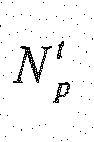

- The selected sub-band index, the position, sign, and amplitude of each pulse in the selected sub-band, and the RMS index are combined as the residual index.
- Next, for the gain compensation encoding, the
encoder 410 calculates exponents based on position information of the MDCT residual coefficient of each track and the quantized MDCT coefficients (S560). The exponents may be calculated as in Equation 13. Since the selected pulses are already coded as the residual index, theencoder 410 sets the exponent of the selected pulses to the minimum exponent value, thereby preventing a waste of bit allocation.
where, pi is a position of the i-th pulse which is relative to the lower boundary index ljmax of the selected sub-band, and Np is the total number of pulses, which may be given in Equation 14.
- The
encoder 410 outputs gain indices by performing the gain encoding process, as described in thegain compensation encoder 116 ofFIG. 2 (S570). As described above, the number of available bits for gain compensation is Bgc. -
FIG. 6 is a flowchart showing a sub-band MDCT residual coefficient encoding process in an MDCT enhancement layer encoding method according to an embodiment of the present invention. - The
error compensation encoder 417 of theencoder 410 calculates a RMS value for the MDCT residual coefficients of the sub-band selected in the step S530, and quantizes the RMS value to output the RMS index (S610). The RMS value (rms) may be calculated as inEquation 15, and may be logarithmically quantized to the RMS index, Irms as in Equation 16.
where,

- The
residual compensation encoder 417 configures tracks for sub-band MDCT residual coefficients to find the pulses (S620). For example, when the number of MDCT residual coefficients of the selected sub-band is 12 and the number of possible positions of each track is 4, the tracks may be configured as in Table 1 or Table 2 depending on the interleaving. Table 1 shows the track structure when the interleaving is not applied and Table 2 shows the track structure when the interleaving is applied.(Table 1) Track Position 0 0, 1, 2, 3 1 4,5,6,7 2 8, 9, 10, 11 (Table 2) Track Position 0 0,3,6,9 1 1, 4, 7, 10 2 2, 5, 8, 11 max . - The
residual compensation encoder 417 selects the predetermined number of pulses in each track using the tracks (S630). For example, if the number of pulses per track is 1, theresidual compensation encoder 417 searches one MDCT residual coefficient having the largest absolute value among MDCT residual coefficients of each track. - The
residual correction encoder 417 divides each pulse searched in the step S630 into its position, sign, and amplitude components, which are quantized respectively. The pulse position is coded as to a relative to starting position of each track (S640). In the examples of Table 1 and Table 2, the position of the searched pulse can be encoded with 2 bits since the number of possible positions in each track is 4. The sign of the searched pulse can be coded with 1 bit (S650), and the pulse amplitude i.e., an absolute value of each searched pulse can be quantized (S660). For example, after reconstructing the quantized RMS value from the RMS index of the step S610 by the dequantization, the pulse amplitudes may be normalized with the quantized RMS value and then may be encoded to the coded value Iamp using scalar quantization or vector quantization.
where,m (i) is the RMS-normalized pulse amplitude of the i-th pulse, and rms_q is the quantized RMS value. - If only one MDCT residual coefficient with the largest absolute valueper track is selected, i.e.,
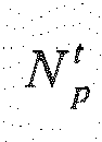

where, t is an index of the track, and p(t) is the selected pulse position in the t-th track and corresponds to pi in Equation 13.
where, s(t) is the selected pulse sign in the t-th track and may be expressed as inEquation 20.
- The MDCT indices, the gain indices, and the residual indices are multiplexed to a bit stream as expressed in Table 3.
(Table 3) Irms Ipos(0) Isign(0) Ipos(1) Isign(1) Ipos(2) Isign(2) Iamp Iopt(k) -
FIG. 7 is a flowchart of an MDCT enhancement layer decoding method according to an embodiment of the present invention. - Referring
FIG. 7 , adecoder 420 receives a bit stream including MDCT indices, residual indices, and gain indices (S710), and demultiplexes the received bit stream into the MDCT indices, the gain indices, and the residual indices (S720). Then, thedecoder 420 dequantizes the MDCT gain indices into the quantized MDCT coefficients (S730), and decodes the residual indices corresponding to sub-band indices jmax to recover MDCT residual coefficients (S740). Thedecoder 420 calculates exponents using the position information of the recovered MDCT residual coefficients and the quantized MDCT coefficients (S750). The exponents may be calculated in the same way as the step S560 ofFIG. 5 . Next, thedecoder 420 performs gain decoding based on the exponents to recover quantized gains, as described in thegain compensation decoder 125 ofFIG. 2 (S760). That is, thedecoder 420 generates a bit allocation table based on the exponents, and recovers the compensation gains for MDCT coefficients from the gain indices using the bit allocation table. As described above, the number of available bits corresponds to Bgc in the gain decoding process. Since the exponent of the selected pulse positions is set to the minimum exponent value, the recovered gain of the selected pulse position can be set to a value that does not change the quantized MDCT coefficient, for example 1. Next, thedecoder 420 compensates the quantized MDCT coefficients with the recovered gains (S770), and compensates the gain-compensated MDCT coefficients as Equation 9 to reconstruct the MDCT coefficients (S780). The gain-compensated MDCT coefficients and the reconstructed MDCT coefficients may be expressed as in Equation 21 and Equation 22, respectively.
where,

-
FIG. 8 is a flowchart showing an MDCT error decoding process in an MDCT decoding method according to an embodiment of the present invention. - Referring to
FIG. 8 , adecoder 420 decodes a sub-band index for error compensation (S810), and dequantize the RMS index to reconstruct a quantized RMS value (S820). Thedecoder 420 decodes position, sign, and amplitude components for pulses of the selected sub-band (S830, S840, and S850), and then denormalizes the decoded pulse amplitude with the quantized RMS value (S860). That is, thedecoder 420 multiplies the decoded pulse amplitude by the quantized RMS value to produce denormalized pulse amplitudes. Next, thedecoder 420 recovers the pulse using the decoded pulse sign and denormalized pulse amplitude (S870). Thedecoder 420 arranges the recovered pulses in accordance with a predetermined track structure using the decoded position of the recovered pulses, to recover quantized MDCT residual coefficients (S880). The recovered MDCT residual coefficients may be expressed as in Equation 23.
where, si is the sign of the i-th pulse, and
Equations 19 and 20 and may be expressed as inEquation 25.

- As such, according to the embodiment of the present invention, a combination of gain compensation scheme and residual compensation scheme can mitigate degradation of sound quality which may be resulted from a spectrum distortion caused by inconsistency between bit allocation in the gain compensation scheme and actual errors.
- While this invention has been described in connection with what is presently considered to be practical embodiments, it is to be understood that the invention is not limited to the disclosed embodiments, but, on the contrary, is intended to cover various modifications and equivalent arrangements included within the spirit and scope of the appended claims.
Claims (37)
- An encoding method of an encoder, the method comprising:transforming an input signal to generate first modified discrete cosine transform (MDCT) coefficients;quantizing the first MDCT coefficients to generate MDCT indices;dequantizing the MDCT indices to generate second MDCT coefficients;computing MDCT residual coefficients using differences between the first MDCT coefficients and the second MDCT coefficients;encoding the MDCT residual coefficients to generate a residual index; andgenerating gain indices corresponding to gains from the first MDCT coefficients and the second MDCT coefficients.
- The method of claim 1, further comprising multiplexing the MDCT indices, the residual index, and the gain indices to generate a bit stream.
- The method of claim 1, wherein generating the residual index comprises:selecting an index of a sub-band with a largest energy of MDCT residual coefficients among a plurality of sub-bands; andgenerating a sub-band index by encoding the selected index,wherein the residual index includes the sub-band index.
- The method of claim 3, wherein the energy of the MDCT residual coefficient of a j-th sub-band is computed as

wherein uj and lj are a lower boundary index and an upper boundary index of the j-th sub-band, respectively, and
E(k) is a k-th MDCT residual coefficient. - The method of claim 3, wherein generating the residual index further comprises encoding MDCT residual coefficients of the selected sub-band.
- The method of claim 5, wherein encoding the MDCT residual coefficients further comprises:configuring a plurality of tracks for MDCT residual coefficients of the selected sub-band;selecting a pulse corresponding to a predetermined number of MDCT residual coefficients having a largest absolute value, among MDCT residual coefficients corresponding to possible positions in each track; andcoding the pulse,wherein the residual index further includes a coded value of the pulse.
- The method of claim 6, wherein coding the pulse comprises:coding a position of the pulse;coding the sign of the pulse; andcoding the amplitude of the pulse,wherein the coded value of the pulse includes a coded value of the position, a coded value of the sign, and a coded value of the amplitude.
- The method of claim 7, wherein the position is a position that is relative to a lower boundary index of the selected sub-band.
- The method of claim 7, wherein encoding the MDCT residual coefficients comprises:computing a root mean square (RMS) value of the MDCT residual coefficients of the selected sub-band; andquantizing the RMS value to generate an RMS index,wherein the residual index further includes the RMS index.
- The method of claim 9, wherein coding the amplitude of the pulse comprises:dequantizing the RMS index to generate a quantized RMS value; andcoding the amplitude of the pulse using the amplitude of the pulse divided by the quantized RMS value.
- The method of claim 6, wherein generating the gain indices comprises:computing exponents as logarithms of magnitudes of the second MDCT coefficients at positions excluding the position of the pulse;setting an exponent to a minimum exponent magnitude at the position of the pulse; andallocating bits for the gain indices based on the exponents.
- The method of claim 11, wherein generating the gain indices further comprises determining the gain indices from the allocated bits, the first MDCT coefficients, and the second MDCT coefficients.
- The method of claim 12, wherein the gain index is determined as i for maximizing

wherein
X(k) is a k-th first MDCT residual coefficient, and
X̂(k) is a k-th second MDCT residual coefficient. - A decoding method of a decoder, the method comprising:receiving MDCT indices, a residual index, and gain indices;dequantizing the MDCT indices to generate first MDCT coefficients;decoding the residual index to recover MDCT residual coefficients;recovering gains from the gain indices using a position of a pulse corresponding to the MDCT residual coefficients and the first MDCT coefficients;compensating gains of the first MDCT coefficients with the recovered gains generating second MDCT coefficients; andcompensating residuals of the second MDCT coefficients with the MDCT residual coefficients.
- The method of claim 14, wherein compensating the residuals comprises adding the MDCT residual coefficients to the second MDCT coefficients.
- The method of claim 15, wherein the MDCT residual coefficients has a value of 0 at positions excluding the position of the pulse.
- The method of claim 14, wherein the residual index includes a sub-band index, and
recovering the MDCT residual coefficients comprises determining a sub-band of the MDCT residual coefficients by decoding the sub-band index. - The method of claim 14, wherein the residual index includes a coded value of the position of the pulse, a coded value of the sign of the pulse, and a coded value of the amplitude of the pulse.
- The method of claim 18, wherein recovering the MDCT residual coefficients comprises:decoding the coded value of the amplitude of the pulse to reconstruct the amplitude of the pulse by;decoding the coded value of the position of the pulse to reconstruct the position of the pulse;decoding the coded value of the sign of the pulse to reconstruct the sign of the pulse; andrecovering the MDCT residual coefficients based on the position, sign, and amplitude of the pulse.
- The method of claim 19, wherein the residual index further includes a root mean square (RMS) index,
wherein recovering the amplitude of the pulse comprises:generating a quantized RMS value from the RMS index; andmultiplying the decoded amplitude of the pulse by the quantized RMS value to recover the amplitude of the pulse. - The method of claim 14, wherein recovering the gains comprises:computing exponents as logarithms of magnitudes of the first MDCT coefficients at positions excluding the position of the pulse;setting an exponent to a minimum exponent magnitude at the position of the pulse; andgenerating a bit allocation table by allocating bits to the gain indices based on the exponents.
- The method of claim 21, wherein recovering the gains further comprises recovering the gains from the gain indices using the bit allocation table.
- The method of claim 14, further comprising recovering a signal by transforming MDCT coefficients, which are generated by compensating the residuals of the second MDCT coefficients, by an inverse MDCT.
- An encoding apparatus, comprising:an MDCT configured to transform an input signal to generate first MDCT coefficients by;an MDCT quantizer configured to quantize the first MDCT coefficients to generate MDCT indices by;an enhancement layer encoder configured to dequantize the MDCT indices to generate second MDCT coefficients, to encode MDCT residual coefficients corresponding to differences between the first MDCT coefficients and the second MDCT coefficients to generate a residual index, and to generate gain indices corresponding to gains of the first MDCT coefficients from the first MDCT coefficients and the second MDCT coefficients; anda multiplexer configured to multiplex the MDCT indices, the residual index, and the gain indices to generate a bit stream.
- The apparatus of claim 24, wherein the enhancement layer encoder comprises a residual compensation encoder configured to select an index of a sub-band having a largest energy of MDCT residual coefficients among a plurality of sub-bands, and generate a sub-band index by encoding the selected index,
wherein the residual index includes the sub-band index. - The apparatus of claim 25, wherein the residual compensation encoder configures a plurality of tracks for MDCT residual coefficients of the selected sub-band, and codes the position, the sign, and the amplitude of a pulse corresponding to a predetermined number of MDCT residual coefficients having the largest absolute value among MDCT residual coefficients corresponding to possible positions in each track,
wherein the residual index further includes a coded value of the position, a coded value of the sign, and a coded value of the amplitude. - The apparatus of claim 26, wherein the residual compensation encoder quantize a root mean square (RMS) value of the MDCT residual coefficients of the selected sub-band to generate an RMS index by,
wherein the residual index further includes the RMS index. - The apparatus of claim 26, wherein the enhancement layer encoder computes exponents as logarithms of magnitudes of the second MDCT coefficients at positions excluding the position of the pulse, sets an exponent to a minimum exponent magnitude at the position of the pulse, and allocates bits for the gain indices based on the exponents.
- The apparatus of claim 28, wherein the gain compensation encoder determines the gain index as i for maximizing

wherein
i is an integer within a range of 0 to (2m-1),
X(k) is the k-th first MDCT residual coefficient, and
X̂(k) is the k-th second MDCT residual coefficient. - A decoding apparatus, comprising:a demultiplexer configured to demultiplex a received bit stream to output MDCT indices, a residual index, and gain indices;an MDCT dequantizer configured to dequantize the MDCT indices to generate first MDCT coefficients; andan enhancement layer decoder configured to decode the residual index, recover gains from the gain indices using a position of a pulse corresponding to the MDCT residual coefficients and the first MDCT coefficients to recover MDCT residual coefficients, compensate gains of the first MDCT coefficients with the recovered gains to generate second MDCT coefficients, and compensate residuals of the second MDCT coefficients with the MDCT residual coefficients.
- The apparatus of claim 30, wherein the enhancement layer decoder comprises a residual compensator configured to add the MDCT residual coefficients to the second MDCT coefficients to compensate the residuals of the second MDCT coefficients.
- The apparatus of claim 30, wherein the residual index includes a coded value of the position of the pulse, a coded value of the sign of the pulse, and a coded value of the amplitude of the pulse,
wherein the enhancement layer decoder comprises a residual compensation decoder configured to decode the coded values of the position, sign, and amplitude of the pulse to recover the position, sign, and amplitude of the pulse. - The apparatus of claim 32, wherein the residual index further includes a root mean square (RMS) index,
wherein the residual compensation decoder generates a quantized RMS value from the RMS index, and multiplies the decoded amplitude of the pulse by the quantized RMS value to recover the amplitude of the pulse. - The apparatus of claim 30, wherein the enhancement layer decoder comprises a gain compensation decoder configured to compute exponents as logarithms of magnitudes of the first MDCT coefficients at positions excluding the position of the pulse, set an exponent to a minimum exponent magnitude at the position of the pulse, generate a bit allocation table by allocating bits to the gain indices based on the exponents, and recover the gains using the gain indices and the bit allocation table.
- The apparatus of claim 30, wherein the enhancement layer decoder comprises a gain compensation decoder configured to compute exponents as logarithms of magnitudes of the first MDCT coefficients at positions excluding the position of the pulse, set an exponent to a minimum exponent magnitude at the position of the pulse, and generate a bit allocation table by allocating bits to the gain indices based on the exponents.
- The apparatus of claim 35, wherein the gain compensation decoder recovers the gains from the gain indices based on the bit allocation table.
- The apparatus of claim 30, further comprising an inverse MDCT configured to recover a signal by transforming MDCT coefficients in which the residuals are compensated, by the inverse MDCT.
Applications Claiming Priority (3)
| Application Number | Priority Date | Filing Date | Title |
|---|---|---|---|
| KR20100029302 | 2010-03-31 | ||
| KR1020110029340A KR101819180B1 (en) | 2010-03-31 | 2011-03-31 | Encoding method and apparatus, and deconding method and apparatus |
| PCT/KR2011/002227 WO2011122875A2 (en) | 2010-03-31 | 2011-03-31 | Encoding method and device, and decoding method and device |
Publications (2)
| Publication Number | Publication Date |
|---|---|
| EP2555186A2 true EP2555186A2 (en) | 2013-02-06 |
| EP2555186A4 EP2555186A4 (en) | 2014-04-16 |
Family
ID=45026904
Family Applications (1)
| Application Number | Title | Priority Date | Filing Date |
|---|---|---|---|
| EP11763047.5A Withdrawn EP2555186A4 (en) | 2010-03-31 | 2011-03-31 | METHOD AND DEVICE FOR ENCODING, AND METHOD AND DEVICE FOR DECODING |
Country Status (6)
| Country | Link |
|---|---|
| US (1) | US9424857B2 (en) |
| EP (1) | EP2555186A4 (en) |
| JP (1) | JP5863765B2 (en) |
| KR (1) | KR101819180B1 (en) |
| CN (2) | CN104392726B (en) |
| WO (1) | WO2011122875A2 (en) |
Families Citing this family (9)
| Publication number | Priority date | Publication date | Assignee | Title |
|---|---|---|---|---|
| JP2014513813A (en) | 2011-04-15 | 2014-06-05 | テレフオンアクチーボラゲット エル エム エリクソン(パブル) | Adaptive gain-shape rate sharing |
| CN102208188B (en) | 2011-07-13 | 2013-04-17 | 华为技术有限公司 | Audio signal encoding-decoding method and device |
| US9602841B2 (en) * | 2012-10-30 | 2017-03-21 | Texas Instruments Incorporated | System and method for decoding scalable video coding |
| TWI557727B (en) * | 2013-04-05 | 2016-11-11 | 杜比國際公司 | Audio processing system, multimedia processing system, method for processing audio bit stream, and computer program product |
| EP3230980B1 (en) * | 2014-12-09 | 2018-11-28 | Dolby International AB | Mdct-domain error concealment |
| KR102807248B1 (en) | 2016-10-11 | 2025-05-14 | 게놈시스 에스에이 | Method and system for transmitting bioinformatics data |
| CN107612658B (en) * | 2017-10-19 | 2020-07-17 | 北京科技大学 | An efficient coding modulation and decoding method based on type B structured trellis code |
| US12159640B2 (en) * | 2021-08-10 | 2024-12-03 | Electronics And Telecommunications Research Institute | Methods of encoding and decoding, encoder and decoder performing the methods |
| KR20240124663A (en) * | 2023-02-09 | 2024-08-19 | 한국전자통신연구원 | Audio signal encoding/decoding method and apparatus for performing the same |
Family Cites Families (25)
| Publication number | Priority date | Publication date | Assignee | Title |
|---|---|---|---|---|
| JP2605681B2 (en) * | 1985-10-14 | 1997-04-30 | ソニー株式会社 | Thin film magnetic head |
| JP3153933B2 (en) | 1992-06-16 | 2001-04-09 | ソニー株式会社 | Data encoding device and method and data decoding device and method |
| US5252782A (en) | 1992-06-29 | 1993-10-12 | E-Systems, Inc. | Apparatus for providing RFI/EMI isolation between adjacent circuit areas on a single circuit board |
| JP3137550B2 (en) * | 1995-02-20 | 2001-02-26 | 松下電器産業株式会社 | Audio encoding / decoding device |
| TW321810B (en) * | 1995-10-26 | 1997-12-01 | Sony Co Ltd | |
| JPH11109995A (en) * | 1997-10-01 | 1999-04-23 | Victor Co Of Japan Ltd | Acoustic signal encoder |
| CA2246532A1 (en) * | 1998-09-04 | 2000-03-04 | Northern Telecom Limited | Perceptual audio coding |
| EP1483759B1 (en) | 2002-03-12 | 2006-09-06 | Nokia Corporation | Scalable audio coding |
| US7275036B2 (en) | 2002-04-18 | 2007-09-25 | Fraunhofer-Gesellschaft Zur Foerderung Der Angewandten Forschung E.V. | Apparatus and method for coding a time-discrete audio signal to obtain coded audio data and for decoding coded audio data |
| DE10217297A1 (en) | 2002-04-18 | 2003-11-06 | Fraunhofer Ges Forschung | Device and method for coding a discrete-time audio signal and device and method for decoding coded audio data |
| JP2005004119A (en) * | 2003-06-16 | 2005-01-06 | Victor Co Of Japan Ltd | Sound signal encoding device and sound signal decoding device |
| KR20050027179A (en) * | 2003-09-13 | 2005-03-18 | 삼성전자주식회사 | Method and apparatus for decoding audio data |
| RU2500043C2 (en) * | 2004-11-05 | 2013-11-27 | Панасоник Корпорэйшн | Encoder, decoder, encoding method and decoding method |
| US7548853B2 (en) * | 2005-06-17 | 2009-06-16 | Shmunk Dmitry V | Scalable compressed audio bit stream and codec using a hierarchical filterbank and multichannel joint coding |
| KR101171098B1 (en) | 2005-07-22 | 2012-08-20 | 삼성전자주식회사 | Scalable speech coding/decoding methods and apparatus using mixed structure |
| KR100848324B1 (en) | 2006-12-08 | 2008-07-24 | 한국전자통신연구원 | Speech Coder and Method |
| AU2007332508B2 (en) * | 2006-12-13 | 2012-08-16 | Iii Holdings 12, Llc | Encoding device, decoding device, and method thereof |
| JP4871894B2 (en) | 2007-03-02 | 2012-02-08 | パナソニック株式会社 | Encoding device, decoding device, encoding method, and decoding method |
| US8527265B2 (en) * | 2007-10-22 | 2013-09-03 | Qualcomm Incorporated | Low-complexity encoding/decoding of quantized MDCT spectrum in scalable speech and audio codecs |
| US8515767B2 (en) * | 2007-11-04 | 2013-08-20 | Qualcomm Incorporated | Technique for encoding/decoding of codebook indices for quantized MDCT spectrum in scalable speech and audio codecs |
| CN101527138B (en) * | 2008-03-05 | 2011-12-28 | 华为技术有限公司 | Coding method and decoding method for ultra wide band expansion, coder and decoder as well as system for ultra wide band expansion |
| US8532998B2 (en) * | 2008-09-06 | 2013-09-10 | Huawei Technologies Co., Ltd. | Selective bandwidth extension for encoding/decoding audio/speech signal |
| WO2010031003A1 (en) * | 2008-09-15 | 2010-03-18 | Huawei Technologies Co., Ltd. | Adding second enhancement layer to celp based core layer |
| US8600737B2 (en) * | 2010-06-01 | 2013-12-03 | Qualcomm Incorporated | Systems, methods, apparatus, and computer program products for wideband speech coding |
| ES2641315T3 (en) * | 2011-03-04 | 2017-11-08 | Telefonaktiebolaget Lm Ericsson (Publ) | Post-quantification gain correction in audio coding |
-
2011
- 2011-03-31 KR KR1020110029340A patent/KR101819180B1/en active Active
- 2011-03-31 CN CN201410655722.0A patent/CN104392726B/en not_active Expired - Fee Related
- 2011-03-31 WO PCT/KR2011/002227 patent/WO2011122875A2/en not_active Ceased
- 2011-03-31 EP EP11763047.5A patent/EP2555186A4/en not_active Withdrawn
- 2011-03-31 CN CN201180026855.6A patent/CN102918590B/en not_active Expired - Fee Related
- 2011-03-31 US US13/638,364 patent/US9424857B2/en not_active Expired - Fee Related
- 2011-03-31 JP JP2013502481A patent/JP5863765B2/en not_active Expired - Fee Related
Also Published As
| Publication number | Publication date |
|---|---|
| KR20110110044A (en) | 2011-10-06 |
| KR101819180B1 (en) | 2018-01-16 |
| JP2013524273A (en) | 2013-06-17 |
| CN104392726A (en) | 2015-03-04 |
| US20130030795A1 (en) | 2013-01-31 |
| CN102918590B (en) | 2014-12-10 |
| WO2011122875A2 (en) | 2011-10-06 |
| JP5863765B2 (en) | 2016-02-17 |
| CN102918590A (en) | 2013-02-06 |
| CN104392726B (en) | 2018-01-02 |
| US9424857B2 (en) | 2016-08-23 |
| WO2011122875A3 (en) | 2011-12-22 |
| EP2555186A4 (en) | 2014-04-16 |
Similar Documents
| Publication | Publication Date | Title |
|---|---|---|
| US9424857B2 (en) | Encoding method and apparatus, and decoding method and apparatus | |
| EP2645367B1 (en) | Encoding/decoding method for audio signals using adaptive sinusoidal coding and apparatus thereof | |
| US10102865B2 (en) | Voice audio encoding device, voice audio decoding device, voice audio encoding method, and voice audio decoding method | |
| EP2239731B1 (en) | Encoding device, decoding device, and method thereof | |
| US8965775B2 (en) | Allocation of bits in an enhancement coding/decoding for improving a hierarchical coding/decoding of digital audio signals | |
| US20250069606A1 (en) | Adaptive Gain-Shape Rate Sharing | |
| US20100063810A1 (en) | Noise-Feedback for Spectral Envelope Quantization | |
| US20120146831A1 (en) | Multi-Rate Algebraic Vector Quantization with Supplemental Coding of Missing Spectrum Sub-Bands | |
| US9454972B2 (en) | Audio and speech coding device, audio and speech decoding device, method for coding audio and speech, and method for decoding audio and speech | |
| EP3128514A2 (en) | High-band encoding method and device, and high-band decoding method and device | |
| US20130132100A1 (en) | Apparatus and method for codec signal in a communication system | |
| US9240192B2 (en) | Device and method for efficiently encoding quantization parameters of spectral coefficient coding | |
| EP2434485A2 (en) | Method and apparatus for encoding and decoding audio signal using hierarchical sinusoidal pulse coding | |
| US10657976B2 (en) | Signal encoding method and apparatus, and signal decoding method and apparatus | |
| WO2011045926A1 (en) | Encoding device, decoding device, and methods therefor | |
| WO2013062201A1 (en) | Method and device for quantizing voice signals in a band-selective manner |
Legal Events
| Date | Code | Title | Description |
|---|---|---|---|
| PUAI | Public reference made under article 153(3) epc to a published international application that has entered the european phase |
Free format text: ORIGINAL CODE: 0009012 |
|
| 17P | Request for examination filed |
Effective date: 20121031 |
|
| AK | Designated contracting states |
Kind code of ref document: A2 Designated state(s): AL AT BE BG CH CY CZ DE DK EE ES FI FR GB GR HR HU IE IS IT LI LT LU LV MC MK MT NL NO PL PT RO RS SE SI SK SM TR |
|
| DAX | Request for extension of the european patent (deleted) | ||
| A4 | Supplementary search report drawn up and despatched |
Effective date: 20140313 |
|
| RIC1 | Information provided on ipc code assigned before grant |
Ipc: G10L 19/02 20130101ALI20140307BHEP Ipc: G10L 19/24 20130101AFI20140307BHEP Ipc: G10L 19/00 20130101ALI20140307BHEP |
|
| 17Q | First examination report despatched |
Effective date: 20160817 |
|
| STAA | Information on the status of an ep patent application or granted ep patent |
Free format text: STATUS: THE APPLICATION IS DEEMED TO BE WITHDRAWN |
|
| 18D | Application deemed to be withdrawn |
Effective date: 20181005 |