EP2554911A2 - Fuel Nozzle - Google Patents
Fuel Nozzle Download PDFInfo
- Publication number
- EP2554911A2 EP2554911A2 EP12177920A EP12177920A EP2554911A2 EP 2554911 A2 EP2554911 A2 EP 2554911A2 EP 12177920 A EP12177920 A EP 12177920A EP 12177920 A EP12177920 A EP 12177920A EP 2554911 A2 EP2554911 A2 EP 2554911A2
- Authority
- EP
- European Patent Office
- Prior art keywords
- fluid
- nozzle
- interior region
- discrete passageways
- discrete
- Prior art date
- Legal status (The legal status is an assumption and is not a legal conclusion. Google has not performed a legal analysis and makes no representation as to the accuracy of the status listed.)
- Withdrawn
Links
- 239000000446 fuel Substances 0.000 title claims abstract description 41
- 239000012530 fluid Substances 0.000 claims abstract description 64
- 238000003754 machining Methods 0.000 claims description 12
- 239000007788 liquid Substances 0.000 claims description 11
- 238000000034 method Methods 0.000 claims description 11
- 230000000694 effects Effects 0.000 claims description 2
- 239000007789 gas Substances 0.000 description 7
- 238000002485 combustion reaction Methods 0.000 description 3
- 238000010276 construction Methods 0.000 description 3
- ATUOYWHBWRKTHZ-UHFFFAOYSA-N Propane Chemical compound CCC ATUOYWHBWRKTHZ-UHFFFAOYSA-N 0.000 description 2
- 239000000463 material Substances 0.000 description 2
- VNWKTOKETHGBQD-UHFFFAOYSA-N methane Chemical compound C VNWKTOKETHGBQD-UHFFFAOYSA-N 0.000 description 2
- 239000003570 air Substances 0.000 description 1
- 230000004075 alteration Effects 0.000 description 1
- 238000000889 atomisation Methods 0.000 description 1
- 238000005266 casting Methods 0.000 description 1
- 230000005611 electricity Effects 0.000 description 1
- 238000005242 forging Methods 0.000 description 1
- 239000000203 mixture Substances 0.000 description 1
- 239000003345 natural gas Substances 0.000 description 1
- 239000001294 propane Substances 0.000 description 1
- 238000006467 substitution reaction Methods 0.000 description 1
- 238000011144 upstream manufacturing Methods 0.000 description 1
Images



Classifications
-
- F—MECHANICAL ENGINEERING; LIGHTING; HEATING; WEAPONS; BLASTING
- F23—COMBUSTION APPARATUS; COMBUSTION PROCESSES
- F23R—GENERATING COMBUSTION PRODUCTS OF HIGH PRESSURE OR HIGH VELOCITY, e.g. GAS-TURBINE COMBUSTION CHAMBERS
- F23R3/00—Continuous combustion chambers using liquid or gaseous fuel
- F23R3/28—Continuous combustion chambers using liquid or gaseous fuel characterised by the fuel supply
- F23R3/36—Supply of different fuels
-
- Y—GENERAL TAGGING OF NEW TECHNOLOGICAL DEVELOPMENTS; GENERAL TAGGING OF CROSS-SECTIONAL TECHNOLOGIES SPANNING OVER SEVERAL SECTIONS OF THE IPC; TECHNICAL SUBJECTS COVERED BY FORMER USPC CROSS-REFERENCE ART COLLECTIONS [XRACs] AND DIGESTS
- Y10—TECHNICAL SUBJECTS COVERED BY FORMER USPC
- Y10T—TECHNICAL SUBJECTS COVERED BY FORMER US CLASSIFICATION
- Y10T29/00—Metal working
- Y10T29/49—Method of mechanical manufacture
- Y10T29/49316—Impeller making
- Y10T29/4932—Turbomachine making
- Y10T29/49323—Assembling fluid flow directing devices, e.g., stators, diaphragms, nozzles
Definitions
- the subject matter disclosed herein relates to a fuel nozzle and, more particularly, to a fuel nozzle with liquid fuel staging and partial mixing.
- liquid and gaseous fuels are mixed with air and other combustible materials and injected as a mixture into a combustor where combustion occurs to produce high energy fluids from which power and electricity can be generated. Often, this mixing occurs upstream from the combustion zone of the combustor in, for example, pre-mixing passages.
- the liquid and gaseous fuels are injected into these pre-mixing passages from internal plenums within fuel nozzles that are often provided in a complex arrangement.
- the complex arrangement of the plenums within fuel nozzles require that the liquid and gaseous fuels follow complicated routes from the internal plenums to the pre-mixing passages and do not allow for certain types of liquid fuel staging or additional forms of partial mixing.
- a fuel nozzle includes a nozzle body defining first and second interior regions for providing a supply of first and second fluids, a collar defining a third interior region and radial slots permitting radial ingress of a third fluid to the third interior region and a nozzle tip interposed between the nozzle body and the collar.
- the nozzle tip defines an annular slot, first discrete passageways by which the first fluid is communicated from the first interior region to the annular slot, second discrete passageways by which the first fluid is communicated from the annular slot to the radial slots, and third discrete passageways by which the second fluid is communicated from the second interior region to the radial slots.
- a method of assembling a nozzle tip of a fuel nozzle for interposition between a nozzle body defining first and second interior regions for providing a supply of first and second fluids and a collar defining a third interior region and radial slots permitting radial ingress of a third fluid to the third interior region is provided.
- the method includes forming an annular slot within the nozzle tip, machining first discrete passageways into the nozzle tip such that the first fluid is able to be communicated from the first interior region to the annular slot, machining second discrete passageways into the nozzle tip such that the first fluid able to be communicated from the annular slot to the radial slots and machining third discrete passageways into the nozzle tip such that the second fluid is able to be communicated from the second interior region to the radial slots.
- a fuel nozzle 10 is provided and provides for liquid fuel staging and partial mixing of liquid fuel, gas and air.
- the fuel nozzle 10 includes a nozzle body 20, a collar 30 and a nozzle tip 40.
- the nozzle body 20 is formed to define a first interior region 21, which may be a discrete hole or multiple discrete holes arranged annularly, for providing a supply of a first fluid for, for example, combustion operations of a gas turbine engine operating in a first mode.
- the nozzle body 20 is further formed to define a second interior region 22 for providing a supply of a second fluid for when the exemplary gas turbine engine is operated in a second mode.
- the collar 30 is formed to define a third interior region 31 and radial slots 32. The radial slots 32 permit radial ingress of a third fluid to the third interior region 31 during most operational modes of the exemplary gas turbine engine.
- the first fluid may include liquid fuel
- the second fluid may include gas, such as natural gas, propane, etc.
- the third fluid may include air, such as compressor discharge air provided from a compressor of the exemplary gas turbine engine.
- other fluids may be provided by or to the first, second and third interior regions 21, 22, 31 in accordance with various applications of the description provided herein.
- the first fluid such as the liquid fuel
- the first fluid may also be provided to the interior region 31 from a center body liquid fuel supply section of the nozzle body 20 via a central injector during start up operations and/or other low flow conditions.
- the nozzle tip 40 is operably interposed between the nozzle body 20 and the collar 30.
- the nozzle tip 40 may be an annular body and may be affixed to an aft end of the nozzle body 20 and welded or brazed to a forward end of the collar 30.
- the nozzle tip 40 is formed to define an annular slot 41, first discrete passageways 42, second discrete passageways 43 and third discrete passageways 44.
- the annular slot 41 is formed as an annular slot within the annular body of the nozzle tip 40 whereas the first and second discrete passageways 42, 43 are formed as circumferentially discrete passageways through the annular body of the nozzle tip 40.
- a number and respective positions of the first and second discrete passageways 42, 43 may correspond with each other and with the radial slots 32 of the collar 30. That is, for each radial slot 32 defined within the collar 30, a first discrete passageway 42 and a second discrete passageway 43 may be defined through the nozzle tip 40.
- the first discrete passageways 42 extend axially from the first interior region 21 along first sections 421 and radially from the first sections 421 to the annular slot 41 along second sections 422.
- the second sections 422 may be oriented with only radial components or at an angle with radial and axial components.
- the first fluid may be communicated from the first interior region 21 to the annular slot 41 via the first sections 421 and the second sections 422.
- the second discrete passageways 43 extend axially and radially from the annular slot 41 to a location just downstream from the radial slots 32 along main sections 431.
- the first fluid may be communicated from the annular slot 41 to the location just downstream from the radial slots 32 and into the third interior region 31.
- the third discrete passageways 44 extend axially and radially from the second interior region 22 to a location just downstream from the radial slots 32 along axial sections 444. As such, the second fluid may be communicated from the second interior region 22 to the location just downstream from the radial slots 32 and into the third interior region 31.
- the fuel nozzle 10 may further include deformable seals 50.
- the deformable seals 50 are formed of compliant material and may be disposed at interfaces between the first interior region 21 and each of the first discrete passageways 42. The deformable seals 50 therefore account for at least axial, radial and/or circumferential differential thermal growth between the nozzle body 20 and the nozzle tip 40 such that leakage of the first fluid is prevented.
- the nozzle tip 40 is formed by, for example, casting, machining, forging or another similar process or processes.
- the annular slot 41 may be formed by similar process or processes.
- the first, second and third passageways 42, 43, 44 can be machined into the nozzle tip 40. Generally, such machining is performed along substantially straight lines with the result being that at least the second sections 422 will extend from an exterior surface of the nozzle tip 40, past the first sections 421 and into the annular slot 41.
- First plugs 60 may, therefore, be provided in the second sections 422 to prevent leakage of the first fluid from the first discrete passageways 42 to an exterior of the nozzle tip 40.
- a second plug 70 may be provided to prevent leakage of the first fluid from the annular slot 41 to the second interior region 22 and to prevent leakage of the second fluid from the second interior regions 22 to the annular slot 41.
- a periphery of the second plug 70 may be welded or otherwise sealed to the nozzle tip 40 such that any leakage across the second plug in either direction is prevented.
- swirler vanes 80 may be disposed in corresponding ones of each of the radial slots 32 to impart a swirling effect to the ingression of the third fluid toward the third interior region 31.
- each swirler vane 80 has a blade body 801, which is angled relative to a radial dimension of the fuel nozzle 10, and a surface 802 that faces the third interior 31.
- Respective outlets 803 of the second and third discrete passageways 43, 44 are defined proximate to the swirler vanes 80 in the corresponding ones of the radial slots 32.
- Each respective outlet 803 may have one or more of an elliptical, a circular and/or a teardrop shape.
- the first fluid may flow along the surface 802 thereby forming a film from which the first fluid is atomized by the third fluid flowing through the radial slots 32 and by the second fluid flowing through the third passageways 44.
- the fuel nozzle 10 may further include injectors 90 disposed about the nozzle tip 40 and the collar 30.
- the injectors 90 are formed to defme respective interiors 901 and are configured to inject the first fluid into the radial slots 32 from the respective interiors thereof.
- the nozzle tip 40 may be further formed to define extensions of the first discrete passageways 42 by which the first fluid is communicated from the first discrete passageways 42 to the respective interiors 901 of the injectors 90. As shown in FIG.
- the injectors 90 may be positioned circumferentially between adjacent swirler vanes 80. With this construction, as the first fluid exits the injectors 90, the first fluid may be atomized by the third fluid flowing through the radial slots 32.
- the fuel nozzle 10 may include the nozzle body 20, the collar 30 and the swirler vanes 80 as substantially described above but with the second discrete passageways 43 extending through corresponding ones of the swirler vanes 80.
- the main sections 431 of the second discrete passageways 43 may extend radially outwardly through the nozzle tip 40 along first portions 4311 and then radially inwardly through the swirler vanes 80 along second portions 4312.
- the annular slot 41 may include first annular slots 410 and second annular slots 411.
- the first annular slots 410 are communicative with a first portion of the first discrete passageways 42 and the second annular slots 411 are communicative with a second portion of the first discrete passageways 42.
- the first fluid may flow into the first and/or the second annular slots 410, 411 and then through the first and second portions 4311, 4312 of the second discrete passageways 42.
- the first fluid may flow from surface 802 and into third interior region 31 with atomization aided by the third fluid.
Landscapes
- Engineering & Computer Science (AREA)
- Chemical & Material Sciences (AREA)
- Combustion & Propulsion (AREA)
- Mechanical Engineering (AREA)
- General Engineering & Computer Science (AREA)
- Nozzles For Spraying Of Liquid Fuel (AREA)
- Nozzles (AREA)
Abstract
A fuel nozzle (10) is provided and includes a nozzle body (20) defining first and second interior regions (21, 22) for providing a supply of first and second fluids, a collar (30) defining a third interior region (31) and radial slots (32) permitting radial ingress of a third fluid to the third interior region (31) and a nozzle tip (40) interposed between the nozzle body (20) and the collar (30). The nozzle tip (40) defines an annular slot (41), first discrete passageways (42) by which the first fluid is communicated from the first interior region (21) to the annular slot (41), second discrete passageways (43) by which the first fluid is communicated from the annular slot (41) to the radial slots (32), and third discrete passageways (44) by which the second fluid is communicated from the second interior region (22) to the radial slots (32).
Description
- The subject matter disclosed herein relates to a fuel nozzle and, more particularly, to a fuel nozzle with liquid fuel staging and partial mixing.
- In gas turbine engines, liquid and gaseous fuels are mixed with air and other combustible materials and injected as a mixture into a combustor where combustion occurs to produce high energy fluids from which power and electricity can be generated. Often, this mixing occurs upstream from the combustion zone of the combustor in, for example, pre-mixing passages. The liquid and gaseous fuels are injected into these pre-mixing passages from internal plenums within fuel nozzles that are often provided in a complex arrangement.
- The complex arrangement of the plenums within fuel nozzles require that the liquid and gaseous fuels follow complicated routes from the internal plenums to the pre-mixing passages and do not allow for certain types of liquid fuel staging or additional forms of partial mixing.
- According to one aspect of the invention, a fuel nozzle is provided and includes a nozzle body defining first and second interior regions for providing a supply of first and second fluids, a collar defining a third interior region and radial slots permitting radial ingress of a third fluid to the third interior region and a nozzle tip interposed between the nozzle body and the collar. The nozzle tip defines an annular slot, first discrete passageways by which the first fluid is communicated from the first interior region to the annular slot, second discrete passageways by which the first fluid is communicated from the annular slot to the radial slots, and third discrete passageways by which the second fluid is communicated from the second interior region to the radial slots.
- According to another aspect of the invention, a method of assembling a nozzle tip of a fuel nozzle for interposition between a nozzle body defining first and second interior regions for providing a supply of first and second fluids and a collar defining a third interior region and radial slots permitting radial ingress of a third fluid to the third interior region is provided. The method includes forming an annular slot within the nozzle tip, machining first discrete passageways into the nozzle tip such that the first fluid is able to be communicated from the first interior region to the annular slot, machining second discrete passageways into the nozzle tip such that the first fluid able to be communicated from the annular slot to the radial slots and machining third discrete passageways into the nozzle tip such that the second fluid is able to be communicated from the second interior region to the radial slots.
- These and other advantages and features will become more apparent from the following description taken in conjunction with the drawings.
- Embodiments of the present invention will now be described, by way of example only, with reference to the accompanying drawings in which:
-
FIG. 1 is a radial view of a fuel nozzle; -
FIG. 2 is an axial view of the fuel nozzle ofFIG. 1 ; -
FIG. 3 is a radial view of a fuel nozzle in accordance with further embodiments; -
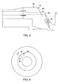
FIG. 4 is an axial view of the fuel nozzle ofFIG. 3 ; and -
FIG. 5 is a radial view a fuel nozzle in accordance with further embodiments. - The detailed description explains embodiments of the invention, together with advantages and features, by way of example with reference to the drawings.
- With reference to
FIGS. 1 and2 , afuel nozzle 10 is provided and provides for liquid fuel staging and partial mixing of liquid fuel, gas and air. Thefuel nozzle 10 includes anozzle body 20, acollar 30 and anozzle tip 40. Thenozzle body 20 is formed to define a firstinterior region 21, which may be a discrete hole or multiple discrete holes arranged annularly, for providing a supply of a first fluid for, for example, combustion operations of a gas turbine engine operating in a first mode. Thenozzle body 20 is further formed to define a secondinterior region 22 for providing a supply of a second fluid for when the exemplary gas turbine engine is operated in a second mode. Thecollar 30 is formed to define a thirdinterior region 31 andradial slots 32. Theradial slots 32 permit radial ingress of a third fluid to the thirdinterior region 31 during most operational modes of the exemplary gas turbine engine. - In accordance with embodiments, the first fluid may include liquid fuel, the second fluid may include gas, such as natural gas, propane, etc., and the third fluid may include air, such as compressor discharge air provided from a compressor of the exemplary gas turbine engine. It is to be understood however, that other fluids may be provided by or to the first, second and third
interior regions interior region 31 from a center body liquid fuel supply section of thenozzle body 20 via a central injector during start up operations and/or other low flow conditions. - The
nozzle tip 40 is operably interposed between thenozzle body 20 and thecollar 30. In particular, thenozzle tip 40 may be an annular body and may be affixed to an aft end of thenozzle body 20 and welded or brazed to a forward end of thecollar 30. Thenozzle tip 40 is formed to define anannular slot 41, firstdiscrete passageways 42, seconddiscrete passageways 43 and thirddiscrete passageways 44. Theannular slot 41 is formed as an annular slot within the annular body of thenozzle tip 40 whereas the first and seconddiscrete passageways nozzle tip 40. A number and respective positions of the first and seconddiscrete passageways radial slots 32 of thecollar 30. That is, for eachradial slot 32 defined within thecollar 30, a firstdiscrete passageway 42 and a seconddiscrete passageway 43 may be defined through thenozzle tip 40. - In accordance with embodiments, the first
discrete passageways 42 extend axially from the firstinterior region 21 alongfirst sections 421 and radially from thefirst sections 421 to theannular slot 41 alongsecond sections 422. Thesecond sections 422 may be oriented with only radial components or at an angle with radial and axial components. In either case, the first fluid may be communicated from the firstinterior region 21 to theannular slot 41 via thefirst sections 421 and thesecond sections 422. The seconddiscrete passageways 43 extend axially and radially from theannular slot 41 to a location just downstream from theradial slots 32 alongmain sections 431. As such, the first fluid may be communicated from theannular slot 41 to the location just downstream from theradial slots 32 and into the thirdinterior region 31. The thirddiscrete passageways 44 extend axially and radially from the secondinterior region 22 to a location just downstream from theradial slots 32 alongaxial sections 444. As such, the second fluid may be communicated from the secondinterior region 22 to the location just downstream from theradial slots 32 and into the thirdinterior region 31. - In accordance with an aspect, the
fuel nozzle 10 may further includedeformable seals 50. Thedeformable seals 50 are formed of compliant material and may be disposed at interfaces between the firstinterior region 21 and each of the firstdiscrete passageways 42. Thedeformable seals 50 therefore account for at least axial, radial and/or circumferential differential thermal growth between thenozzle body 20 and thenozzle tip 40 such that leakage of the first fluid is prevented. - In the assembly of the
fuel nozzle 10, thenozzle tip 40 is formed by, for example, casting, machining, forging or another similar process or processes. Theannular slot 41 may be formed by similar process or processes. The first, second andthird passageways nozzle tip 40. Generally, such machining is performed along substantially straight lines with the result being that at least thesecond sections 422 will extend from an exterior surface of thenozzle tip 40, past thefirst sections 421 and into theannular slot 41.First plugs 60 may, therefore, be provided in thesecond sections 422 to prevent leakage of the first fluid from the firstdiscrete passageways 42 to an exterior of thenozzle tip 40. In addition, since theannular slot 41 can be open to the secondinterior region 22, asecond plug 70 may be provided to prevent leakage of the first fluid from theannular slot 41 to the secondinterior region 22 and to prevent leakage of the second fluid from the secondinterior regions 22 to theannular slot 41. A periphery of thesecond plug 70 may be welded or otherwise sealed to thenozzle tip 40 such that any leakage across the second plug in either direction is prevented. - Still referring to
FIGS. 1 and2 ,swirler vanes 80 may be disposed in corresponding ones of each of theradial slots 32 to impart a swirling effect to the ingression of the third fluid toward the thirdinterior region 31. As shown inFIG. 2 , eachswirler vane 80 has ablade body 801, which is angled relative to a radial dimension of thefuel nozzle 10, and asurface 802 that faces thethird interior 31.Respective outlets 803 of the second and thirddiscrete passageways swirler vanes 80 in the corresponding ones of theradial slots 32. Eachrespective outlet 803 may have one or more of an elliptical, a circular and/or a teardrop shape. With this construction, as the first fluid exits the second discrete passageways, the first fluid may flow along thesurface 802 thereby forming a film from which the first fluid is atomized by the third fluid flowing through theradial slots 32 and by the second fluid flowing through thethird passageways 44. - With reference to
FIGS. 3 and 4 , in accordance with further embodiments, thefuel nozzle 10 may further includeinjectors 90 disposed about thenozzle tip 40 and thecollar 30. Theinjectors 90 are formed to defmerespective interiors 901 and are configured to inject the first fluid into theradial slots 32 from the respective interiors thereof. As shown inFIG. 3 , thenozzle tip 40 may be further formed to define extensions of the firstdiscrete passageways 42 by which the first fluid is communicated from the firstdiscrete passageways 42 to therespective interiors 901 of theinjectors 90. As shown inFIG. 4 , where theswirler vanes 80 are disposed in each of theradial slots 32, in accordance with embodiments, theinjectors 90 may be positioned circumferentially betweenadjacent swirler vanes 80. With this construction, as the first fluid exits theinjectors 90, the first fluid may be atomized by the third fluid flowing through theradial slots 32. - With reference to
FIG. 5 and, in accordance with further embodiments, thefuel nozzle 10 may include thenozzle body 20, thecollar 30 and the swirler vanes 80 as substantially described above but with the seconddiscrete passageways 43 extending through corresponding ones of theswirler vanes 80. In these embodiments, themain sections 431 of the seconddiscrete passageways 43 may extend radially outwardly through thenozzle tip 40 alongfirst portions 4311 and then radially inwardly through the swirler vanes 80 alongsecond portions 4312. In addition, in these embodiments, theannular slot 41 may include firstannular slots 410 and secondannular slots 411. The firstannular slots 410 are communicative with a first portion of the firstdiscrete passageways 42 and the secondannular slots 411 are communicative with a second portion of the firstdiscrete passageways 42. With this construction, the first fluid may flow into the first and/or the secondannular slots second portions discrete passageways 42. As the first fluid exits thesecond portions 4312 of the seconddiscrete passageways 42, the first fluid may flow fromsurface 802 and into thirdinterior region 31 with atomization aided by the third fluid. - While the invention has been described in detail in connection with only a limited number of embodiments, it should be readily understood that the invention is not limited to such disclosed embodiments. Rather, the invention can be modified to incorporate any number of variations, alterations, substitutions or equivalent arrangements not heretofore described, but which are commensurate with the spirit and scope of the invention. Additionally, while various embodiments of the invention have been described, it is to be understood that aspects of the invention may include only some of the described embodiments. Accordingly, the invention is not to be seen as limited by the foregoing description, but is only limited by the scope of the appended claims.
Claims (13)
- A fuel nozzle (10), comprising:a nozzle body (20) defining first and second interior regions (21, 22) for providing a supply of first and second fluids;a collar (30) defining a third interior region (31) and radial slots (32) permitting radial ingress of a third fluid to the third interior region (31); anda nozzle tip (40) interposed between the nozzle body (20) and the collar (30), the nozzle tip (40) defining:an annular slot (41),first discrete passageways (42) by which the first fluid is communicated from the first interior region (21) to the annular slot (41),second discrete (43) passageways by which the first fluid is communicated from the annular slot (41) to the radial slots (32), andthird discrete passageways (44) by which the second fluid is communicated from the second interior region (22) to the radial slots (32).
- The fuel nozzle (10) according to claim 1, wherein the first fluid comprises liquid fuel, the second fluid comprises gas and the third fluid comprises air.
- The fuel nozzle (10) according to claim 1 or 2, further comprising seals (50) disposed between the first interior region (21) and the first discrete passageways (42).
- The fuel nozzle (10) according to any of claims 1 to 3, further comprising plugs (60, 70) to prevent leakage from the first discrete passageways (42) to an exterior of the nozzle tip (40) and from the annular slot (41) to the second interior region (22).
- The fuel nozzle (10) according to any of claims 1 to 4, further comprising swirler vanes (80) disposed in each of the radial slots (32) to impart a swirling effect to the third fluid.
- The fuel nozzle (10) according to claim 5, wherein respective outlets (803) of the second and third discrete passageways (42, 43) are defined proximate to the swirler vanes (80) in corresponding ones of the radial slots (32).
- The fuel nozzle (10) according to claim 6, wherein each respective outlet (803) has one or more of an elliptical, a circular or a teardrop shape.
- The fuel nozzle (10) according to any preceding claim, further comprising injectors (90) disposed about the nozzle tip (40) and the collar (30) to inject the first fluid into the radial slots (32) from respective interiors (901) thereof,
the nozzle tip (40) defining extensions of the first discrete passageways (42) by which the first fluid is communicated from the first discrete passageways (42) to the respective interiors (901) of the injectors (90). - The fuel nozzle according to any preceding claim, wherein the annular slot (41) comprises:first annular slots (410) communicative with a first portion (421) of the first discrete passageways (42); andsecond annular slots (411) communicative with a second portion (422) of the first discrete passageways (42).
- A method of assembling a nozzle tip (40) of a fuel nozzle (10) for interposition between a nozzle body (20) defining first and second interior regions (21, 22) for providing a supply of first and second fluids and a collar (30) defining a third interior region (31) and radial slots (32) permitting radial ingress of a third fluid to the third interior region (31), the method comprising:forming an annular slot (41) within the nozzle tip (40);machining first discrete passageways (42) into the nozzle tip (40) such that the first fluid is able to be communicated from the first interior region (21) to the annular slot (41);machining second discrete passageways (43) into the nozzle tip (40) such that the first fluid is able to be communicated from the annular slot (41) to the radial slots (32); andmachining third discrete passageways (44) into the nozzle tip (40) such that the second fluid is able to be communicated from the second interior region (22) to the radial slots (32).
- The method according to claim 10, further comprising plugging the first discrete passageways (42).
- The method according to claim 10 or 11, wherein the machining comprises machining of the second and third discrete passageways (43,44) to have one or more of an elliptical, a circular or a teardrop shape.
- The method according to claim 10, 11 or 12, further comprising disposing injectors (90) about the nozzle tip (40) and the collar to inject the first fluid into the radial slots (32) from respective interiors thereof,
the machining comprising machining extensions of the first discrete passageways (42) by which the first fluid is able to be communicated from the first discrete passageways (42) to the respective interiors of the injectors (90).
Applications Claiming Priority (1)
| Application Number | Priority Date | Filing Date | Title |
|---|---|---|---|
| US13/196,611 US9127844B2 (en) | 2011-08-02 | 2011-08-02 | Fuel nozzle |
Publications (1)
| Publication Number | Publication Date |
|---|---|
| EP2554911A2 true EP2554911A2 (en) | 2013-02-06 |
Family
ID=46679134
Family Applications (1)
| Application Number | Title | Priority Date | Filing Date |
|---|---|---|---|
| EP12177920A Withdrawn EP2554911A2 (en) | 2011-08-02 | 2012-07-25 | Fuel Nozzle |
Country Status (3)
| Country | Link |
|---|---|
| US (1) | US9127844B2 (en) |
| EP (1) | EP2554911A2 (en) |
| CN (1) | CN102913951A (en) |
Families Citing this family (7)
| Publication number | Priority date | Publication date | Assignee | Title |
|---|---|---|---|---|
| US10094352B2 (en) * | 2012-02-16 | 2018-10-09 | Delavan Inc. | Swirl impingement prefilming |
| CN107001098B (en) * | 2014-10-03 | 2020-09-29 | 康宁股份有限公司 | Method and apparatus for reducing sheet width attenuation of sheet glass |
| US10337738B2 (en) | 2016-06-22 | 2019-07-02 | General Electric Company | Combustor assembly for a turbine engine |
| US11022313B2 (en) | 2016-06-22 | 2021-06-01 | General Electric Company | Combustor assembly for a turbine engine |
| US10197279B2 (en) | 2016-06-22 | 2019-02-05 | General Electric Company | Combustor assembly for a turbine engine |
| KR102142140B1 (en) | 2018-09-17 | 2020-08-06 | 두산중공업 주식회사 | Fuel nozzle, combustor and gas turbine having the same |
| US11181269B2 (en) | 2018-11-15 | 2021-11-23 | General Electric Company | Involute trapped vortex combustor assembly |
Family Cites Families (8)
| Publication number | Priority date | Publication date | Assignee | Title |
|---|---|---|---|---|
| US5351477A (en) | 1993-12-21 | 1994-10-04 | General Electric Company | Dual fuel mixer for gas turbine combustor |
| US5899076A (en) * | 1996-12-20 | 1999-05-04 | United Technologies Corporation | Flame disgorging two stream tangential entry nozzle |
| US5966937A (en) | 1997-10-09 | 1999-10-19 | United Technologies Corporation | Radial inlet swirler with twisted vanes for fuel injector |
| DE19905995A1 (en) * | 1999-02-15 | 2000-08-17 | Asea Brown Boveri | Injection lance or nozzle for liquid and gaseous fuel in combustion chamber is part of secondary or tertiary burner around which flows hot gas jet in main flow direction |
| US6547163B1 (en) | 1999-10-01 | 2003-04-15 | Parker-Hannifin Corporation | Hybrid atomizing fuel nozzle |
| CN101365913A (en) * | 2005-11-04 | 2009-02-11 | 阿尔斯托姆科技有限公司 | fuel nozzle |
| US7703287B2 (en) * | 2006-10-31 | 2010-04-27 | Delavan Inc | Dynamic sealing assembly to accommodate differential thermal growth of fuel injector components |
| US8661779B2 (en) * | 2008-09-26 | 2014-03-04 | Siemens Energy, Inc. | Flex-fuel injector for gas turbines |
-
2011
- 2011-08-02 US US13/196,611 patent/US9127844B2/en active Active
-
2012
- 2012-07-25 EP EP12177920A patent/EP2554911A2/en not_active Withdrawn
- 2012-08-02 CN CN2012102730226A patent/CN102913951A/en active Pending
Non-Patent Citations (1)
| Title |
|---|
| None |
Also Published As
| Publication number | Publication date |
|---|---|
| US20130031905A1 (en) | 2013-02-07 |
| CN102913951A (en) | 2013-02-06 |
| US9127844B2 (en) | 2015-09-08 |
Similar Documents
| Publication | Publication Date | Title |
|---|---|---|
| EP3282191B1 (en) | Pilot premix nozzle and fuel nozzle assembly | |
| EP4174379B1 (en) | Methods of operating a turbomachine combustor on hydrogen | |
| US8904798B2 (en) | Combustor | |
| US9222673B2 (en) | Fuel nozzle and method of assembling the same | |
| JP6900198B2 (en) | Gas cartridge for premixed fuel nozzle | |
| US9127844B2 (en) | Fuel nozzle | |
| EP3341656B1 (en) | Fuel nozzle assembly for a gas turbine | |
| US20140033722A1 (en) | Fuel-Air Mixer For Use With A Combustor Assembly | |
| CN106066048B (en) | Premix pilot nozzle | |
| EP3376109B1 (en) | Dual-fuel fuel nozzle with liquid fuel tip | |
| EP2613091B1 (en) | Flowsleeve of a turbomachine component | |
| EP4206534B1 (en) | Turbine engine fuel premixer | |
| EP2592349A2 (en) | Combustor and method for supplying fuel to a combustor | |
| US20180340689A1 (en) | Low Profile Axially Staged Fuel Injector | |
| EP3988846B1 (en) | Integrated combustion nozzle having a unified head end | |
| US10746101B2 (en) | Annular fuel manifold with a deflector | |
| EP3415818B1 (en) | Fuel supply assembly | |
| US20250198620A1 (en) | Fuel injection assembly having partial direct injectors | |
| CN103925617B (en) | The stream set of turbomachinery component | |
| US20170350321A1 (en) | Bundled Tube Fuel Nozzle Assembly with Tube Extensions |
Legal Events
| Date | Code | Title | Description |
|---|---|---|---|
| PUAI | Public reference made under article 153(3) epc to a published international application that has entered the european phase |
Free format text: ORIGINAL CODE: 0009012 |
|
| AK | Designated contracting states |
Kind code of ref document: A2 Designated state(s): AL AT BE BG CH CY CZ DE DK EE ES FI FR GB GR HR HU IE IS IT LI LT LU LV MC MK MT NL NO PL PT RO RS SE SI SK SM TR |
|
| AX | Request for extension of the european patent |
Extension state: BA ME |
|
| STAA | Information on the status of an ep patent application or granted ep patent |
Free format text: STATUS: THE APPLICATION IS DEEMED TO BE WITHDRAWN |
|
| 18D | Application deemed to be withdrawn |
Effective date: 20150203 |