EP2554908A2 - Combustor leaf seal arrangement - Google Patents
Combustor leaf seal arrangement Download PDFInfo
- Publication number
- EP2554908A2 EP2554908A2 EP12178104A EP12178104A EP2554908A2 EP 2554908 A2 EP2554908 A2 EP 2554908A2 EP 12178104 A EP12178104 A EP 12178104A EP 12178104 A EP12178104 A EP 12178104A EP 2554908 A2 EP2554908 A2 EP 2554908A2
- Authority
- EP
- European Patent Office
- Prior art keywords
- radially
- nozzle
- extending
- seal assembly
- edge
- Prior art date
- Legal status (The legal status is an assumption and is not a legal conclusion. Google has not performed a legal analysis and makes no representation as to the accuracy of the status listed.)
- Withdrawn
Links
- 239000000446 fuel Substances 0.000 claims abstract description 4
- 239000007787 solid Substances 0.000 claims description 11
- 238000007789 sealing Methods 0.000 description 3
- 239000002184 metal Substances 0.000 description 2
- 230000000712 assembly Effects 0.000 description 1
- 238000000429 assembly Methods 0.000 description 1
- 238000001816 cooling Methods 0.000 description 1
- 238000005516 engineering process Methods 0.000 description 1
- 230000002708 enhancing effect Effects 0.000 description 1
- 230000003993 interaction Effects 0.000 description 1
Images


Classifications
-
- F—MECHANICAL ENGINEERING; LIGHTING; HEATING; WEAPONS; BLASTING
- F23—COMBUSTION APPARATUS; COMBUSTION PROCESSES
- F23R—GENERATING COMBUSTION PRODUCTS OF HIGH PRESSURE OR HIGH VELOCITY, e.g. GAS-TURBINE COMBUSTION CHAMBERS
- F23R3/00—Continuous combustion chambers using liquid or gaseous fuel
- F23R3/28—Continuous combustion chambers using liquid or gaseous fuel characterised by the fuel supply
- F23R3/283—Attaching or cooling of fuel injecting means including supports for fuel injectors, stems, or lances
-
- F—MECHANICAL ENGINEERING; LIGHTING; HEATING; WEAPONS; BLASTING
- F23—COMBUSTION APPARATUS; COMBUSTION PROCESSES
- F23R—GENERATING COMBUSTION PRODUCTS OF HIGH PRESSURE OR HIGH VELOCITY, e.g. GAS-TURBINE COMBUSTION CHAMBERS
- F23R3/00—Continuous combustion chambers using liquid or gaseous fuel
- F23R3/28—Continuous combustion chambers using liquid or gaseous fuel characterised by the fuel supply
- F23R3/286—Continuous combustion chambers using liquid or gaseous fuel characterised by the fuel supply having fuel-air premixing devices
-
- F—MECHANICAL ENGINEERING; LIGHTING; HEATING; WEAPONS; BLASTING
- F23—COMBUSTION APPARATUS; COMBUSTION PROCESSES
- F23R—GENERATING COMBUSTION PRODUCTS OF HIGH PRESSURE OR HIGH VELOCITY, e.g. GAS-TURBINE COMBUSTION CHAMBERS
- F23R2900/00—Special features of, or arrangements for continuous combustion chambers; Combustion processes therefor
- F23R2900/00012—Details of sealing devices
Definitions
- This invention relates generally to gas turbine combustor technology and, more specifically, to minimizing cooling air leakage between adjacent wedge-shaped combustor nozzles.
- spring-loaded leaf seals are used to seal between two concentric surfaces, for example, between the combustor liner and surrounding flow sleeve (see, for example, commonly owned U.S. patent No. 6,427,446 ). These seals are often referred to as “hula seals” in that they consist of a series of short, pre-bent leaf seals formed into a circle.
- a plurality of wedge-shaped sector nozzles (sometimes referred to herein as "sector nozzles”) are arrayed in annular fashion about a center nozzle, with radially-oriented side plates of the adjacent sector nozzles closely adjacent one another.
- a substantially wedge-shaped sector nozzle comprising a nozzle body having inner and outer arcuate plates connected by diverging radially-oriented side surfaces and a nozzle plate at an aft end of the nozzle body formed with an array of fuel orifices; one of the diverging radially-oriented side surfaces supporting a radially-oriented leaf seal adapted to seal against a flat surface of an adjacent similarly-shaped sector nozzle.
- a seal assembly for use with a wedge-shaped sector nozzle of a gas turbine combustor, the seal assembly comprising a plurality of substantially parallel spring fingers joined along a solid edge extending substantially perpendicularly to the plurality of substantially parallel spring fingers, and a pair of relatively rigid inner and outer plates attached at opposite ends of the solid edge.
- the invention relates to a pair of turbine sector nozzles each comprising inner and outer arcuate segment walls connected by diverging, radially-oriented side plates, wherein one of said radially oriented side plates supports a radially-oriented leaf seal assembly engaged against a flat surface of an adjacent similarly-shaped sector nozzle.
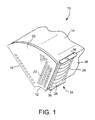
- a sector nozzle 10 for a gas turbine combustor comprises a radially inner arcuate wall segment 12 and a larger, radially outer arcuate wall segment 14, connected by diverging, radially-oriented side plates 16, 18.
- the aft or outlet end of the sector nozzle is provided with an apertured plate 20 formed with an array of fuel/air nozzle orifices 22.
- plural similar sector nozzles 10 will be assembled in an annular array about a combustor center nozzle (see center nozzle 44 in Fig. 8 ).
- the invention is not limited, however, to any specific sector nozzle or apertured plate configuration.
- a side plate leaf seal assembly 24 is attached to one of the diverging, radially-oriented side plates of each sector nozzle (side plate 18 in this example) such that the seal assembly 24 will, in use, engage a substantially flat, radially-oriented side plate of an adjacent sector nozzle.
- the right side plate 18 supports an exemplary seal assembly 24, while the left side plate 16 is substantially flat and will be engaged by a similar seal assembly 24 on the right side plate of an adjacent sector nozzle (not shown in Fig. 1 ).
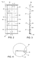
- the side plate leaf seal assembly 24 includes a plurality of convex, metal leaf springs or spring fingers 26 which are joined along a solid radially-extending edge or base 28 at the forward end of the seal assembly (the end remote from the apertured plate 20).
- the spring fingers 26 and edge or base 28 may be formed from a single metal sheet that is slotted to form the adjacent spring fingers 26.
- axially-extending slots 30 are open at the aft end of the spring fingers and terminate at the radially-extending edge or base 28.
- slots 30 terminate at enlarged openings 32 which allow the spring fingers 26 to flex more freely.
- the radially inner and outer spring fingers may be formed with a partial cutout 33(one shown in Fig. 4 ) for the same purpose.
- the spring fingers 26 are convexly-curved in an axial direction, such that they bow outwardly to enable resilient, sealing engagement with the flat side plate of an adjacent sector nozzle. More specifically, the edge or base 28 and the remote free ends 34 of the spring fingers are substantially flat, with the convexly curved portions extending therebetween.
- a pair of leaf spring assemblies 24 are welded together, in a nested relationship along their respective bases 28, but with the spring fingers 27 staggered in a radial direction so that, as viewed in Fig. 3 , the underlying spring fingers 27 overlap the slots 30 between spring fingers 26, thereby enhancing the sealing effectiveness by reducing potential leakage paths.
- the radially inner and outer ends of the spring finger assembly 24 are provided with substantially identical, relatively rigid end plates 36, 38 that lie in axially-extending planes and are substantially perpendicular to the edge or base 28.
- the outer end plate 36 is of a relatively simple, flat, rectangular shape and is welded to the edge or base 28, but not to the adjacent spring finger 26.
- the inner end plate 38 is similarly shaped and attached to the edge or base 28, but again, not to the adjacent spring finger.
- the radially inner surface 40 may be arched or concavely curved (see Fig. 6 ) to generally conform to the annular spring finger seal 42 on the center nozzle 44 (see also Figs. 8 and 9 ) with which it is engaged.
- transverse edges 46, 48 of the inner end plate 38 may be received in notches 50, 52 formed in the adjacent inner wall segments, 12, 13 of adjacent sector nozzles 10, 11 thereby permitting the radially inner surface of the end plate 38 to remain substantially flush with the radially inner surfaces of the inner wall segments 12, 13.
- a similar notched arrangement in the adjacent sector nozzles may be provided in the outer segment walls for accommodating the radially outer end plate 36.
- a pair of elongated, axially-oriented shape-adaptor elements or seal wedges 58, 60 may be weld to the adjacent corners to facilitate assembly of the side plate leaf seal assembly 24, and to obtain more effective sealing at the rounded inner corners by eliminating empty space that might otherwise provide a leakage path of adjacent sector nozzles.
- the seal wedges 58, 60 may also be notched or grooved as at 62, 64 to receive the transverse edges of the inner end plate 38 of the leaf seal assembly 24, for essentially the same reasons as applied in connection with the arrangement in Fig. 9 .
- the seal wedges 58, 60 are elongate, generally triangular-shaped elements as best seen in Fig. 11 each having a pair of substantially flat sides 66, 68 joined by a curved surface 70.
- the seal wedges are adapted to be welded to the curved corners 54, 56 such that the curved surface 84 engages the similarly curved nozzle surfaces, as best seen in Figs. 10 and 11 .
Landscapes
- Engineering & Computer Science (AREA)
- Chemical & Material Sciences (AREA)
- Combustion & Propulsion (AREA)
- Mechanical Engineering (AREA)
- General Engineering & Computer Science (AREA)
- Turbine Rotor Nozzle Sealing (AREA)
- Gasket Seals (AREA)
- Structures Of Non-Positive Displacement Pumps (AREA)
- Spray-Type Burners (AREA)
Abstract
Description
- This invention relates generally to gas turbine combustor technology and, more specifically, to minimizing cooling air leakage between adjacent wedge-shaped combustor nozzles.
- In certain gas turbine combustors, spring-loaded leaf seals are used to seal between two concentric surfaces, for example, between the combustor liner and surrounding flow sleeve (see, for example, commonly owned
U.S. patent No. 6,427,446 ). These seals are often referred to as "hula seals" in that they consist of a series of short, pre-bent leaf seals formed into a circle. In certain combustor nozzle arrangements, a plurality of wedge-shaped sector nozzles (sometimes referred to herein as "sector nozzles") are arrayed in annular fashion about a center nozzle, with radially-oriented side plates of the adjacent sector nozzles closely adjacent one another. There is a need for a way to seal between the side plates of adjacent sector nozzles, a task made more difficult by the use of hula seals on the center nozzle about which the sector nozzles are arranged, as well as on the inner surface of the surrounding combustor liner. - In a first exemplary but nonlimiting aspect, there is provided a substantially wedge-shaped sector nozzle comprising a nozzle body having inner and outer arcuate plates connected by diverging radially-oriented side surfaces and a nozzle plate at an aft end of the nozzle body formed with an array of fuel orifices; one of the diverging radially-oriented side surfaces supporting a radially-oriented leaf seal adapted to seal against a flat surface of an adjacent similarly-shaped sector nozzle.
- In another exemplary but nonlimiting aspect, there is provided a seal assembly for use with a wedge-shaped sector nozzle of a gas turbine combustor, the seal assembly comprising a plurality of substantially parallel spring fingers joined along a solid edge extending substantially perpendicularly to the plurality of substantially parallel spring fingers, and a pair of relatively rigid inner and outer plates attached at opposite ends of the solid edge.
- In still another exemplary but nonlimiting aspect, the invention relates to a pair of turbine sector nozzles each comprising inner and outer arcuate segment walls connected by diverging, radially-oriented side plates, wherein one of said radially oriented side plates supports a radially-oriented leaf seal assembly engaged against a flat surface of an adjacent similarly-shaped sector nozzle.
- The invention will now be described in connection with the drawings identified below.
-
-
Fig. 1 is a partial perspective view of a sector nozzle for a turbine combustor including a side plate leaf seal in accordance with an exemplary but nonlimiting embodiment; -
Fig. 2 is a side elevation of the leaf seal shown inFig. 1 ; -
Fig. 3 is and end elevation of the leaf seal shown inFig. 2 ; -
Fig. 4 is an enlarged detail taken fromFig. 2 ; -
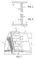
Fig. 5 is a section taken along the line 5-5 inFig. 2 ; -
Fig. 6 is a section taken along the line 6-6 inFig. 2 ; -
Fig. 7 is another partial perspective view of the sector nozzle and side plate seal shown inFig. 1 ; -
Fig. 8 is still another partial perspective view of the sector nozzle and side plate seal, showing the interaction between the side plate seal and a hula seal secured about the center nozzle; -
Fig. 9 is a partial perspective view showing the inner end plate of the side plate leaf seal engaged with the center nozzle hula seal; -
Fig. 10 illustrates an alternative exemplary embodiment wherein seal wedges are added to rounded nozzle corners to facilitate a better fit with the side inner end plate of the plate leaf seal; and -
Fig. 11 is a partial perspective view showing plural pairs of the seal wedges shown inFig. 10 . - With reference initially to
Fig. 1 , asector nozzle 10 for a gas turbine combustor comprises a radially innerarcuate wall segment 12 and a larger, radially outerarcuate wall segment 14, connected by diverging, radially-orientedside plates apertured plate 20 formed with an array of fuel/air nozzle orifices 22. It will be understood that pluralsimilar sector nozzles 10 will be assembled in an annular array about a combustor center nozzle (seecenter nozzle 44 inFig. 8 ). The invention is not limited, however, to any specific sector nozzle or apertured plate configuration. - In the exemplary but nonlimiting embodiment, a side plate
leaf seal assembly 24 is attached to one of the diverging, radially-oriented side plates of each sector nozzle (side plate 18 in this example) such that theseal assembly 24 will, in use, engage a substantially flat, radially-oriented side plate of an adjacent sector nozzle. In other words, and as viewed inFig. 1 , theright side plate 18 supports anexemplary seal assembly 24, while theleft side plate 16 is substantially flat and will be engaged by asimilar seal assembly 24 on the right side plate of an adjacent sector nozzle (not shown inFig. 1 ). - With additional reference to
Figs. 2-7 , the side plateleaf seal assembly 24 includes a plurality of convex, metal leaf springs orspring fingers 26 which are joined along a solid radially-extending edge orbase 28 at the forward end of the seal assembly (the end remote from the apertured plate 20). Thespring fingers 26 and edge orbase 28 may be formed from a single metal sheet that is slotted to form theadjacent spring fingers 26. Thus, axially-extendingslots 30 are open at the aft end of the spring fingers and terminate at the radially-extending edge orbase 28. Note thatslots 30 terminate at enlargedopenings 32 which allow thespring fingers 26 to flex more freely. The radially inner and outer spring fingers may be formed with a partial cutout 33(one shown inFig. 4 ) for the same purpose. - The
spring fingers 26 are convexly-curved in an axial direction, such that they bow outwardly to enable resilient, sealing engagement with the flat side plate of an adjacent sector nozzle. More specifically, the edge orbase 28 and the remotefree ends 34 of the spring fingers are substantially flat, with the convexly curved portions extending therebetween. In an exemplary but nonlimiting embodiment, best appreciated fromFigs. 3 ,5 and 6 , a pair ofleaf spring assemblies 24 are welded together, in a nested relationship along theirrespective bases 28, but with thespring fingers 27 staggered in a radial direction so that, as viewed inFig. 3 , theunderlying spring fingers 27 overlap theslots 30 betweenspring fingers 26, thereby enhancing the sealing effectiveness by reducing potential leakage paths. - The radially inner and outer ends of the
spring finger assembly 24 are provided with substantially identical, relativelyrigid end plates base 28. Theouter end plate 36 is of a relatively simple, flat, rectangular shape and is welded to the edge orbase 28, but not to theadjacent spring finger 26. Theinner end plate 38 is similarly shaped and attached to the edge orbase 28, but again, not to the adjacent spring finger. For theinner end plate 38, however, the radiallyinner surface 40 may be arched or concavely curved (seeFig. 6 ) to generally conform to the annular spring finger seal 42 on the center nozzle 44 (see alsoFigs. 8 and9 ) with which it is engaged. - With reference now to
Fig. 9 , it may be seen thattransverse edges inner end plate 38 may be received innotches adjacent sector nozzles end plate 38 to remain substantially flush with the radially inner surfaces of theinner wall segments outer end plate 36. - With reference now to
Fig. 10 , in the event the inner and/or nozzle sector side plates are rounded (seerounded corners 54, 56), it may be advantageous to weld a pair of elongated, axially-oriented shape-adaptor elements orseal wedges leaf seal assembly 24, and to obtain more effective sealing at the rounded inner corners by eliminating empty space that might otherwise provide a leakage path of adjacent sector nozzles. In addition, theseal wedges inner end plate 38 of theleaf seal assembly 24, for essentially the same reasons as applied in connection with the arrangement inFig. 9 . Theseal wedges Fig. 11 each having a pair of substantiallyflat sides curved corners Figs. 10 and11 .
Claims (13)
- A substantially wedge-shaped sector nozzle (10) comprising a nozzle body having inner and outer arcuate segments (12,14) connected by diverging radially-oriented side plates (16,18) and a nozzle plate (20) at an aft end of the nozzle body formed with an array of fuel orifices (22); one of said diverging radially-oriented side plates supporting a radially-oriented leaf seal assembly (24) adapted to seal against a flat plate of an adjacent similarly-shaped sector nozzle.
- The substantially wedge-shaped sector nozzle of claim 1 wherein said radially-oriented leaf seal assembly (24) comprises a plurality of radially-aligned, axially-extending spring fingers (26) joined along a solid, radially-extending edge (28).
- The substantially wedge-shaped sector nozzle of claim 2 and further comprising first and second axially-extending end-plates (36,38) fixed at opposite radially outer and inner ends of said solid, radially-extending edge (28).
- The substantially wedge-shaped sector nozzle of claim 3 wherein said first and second end-plates (36,38) are substantially parallel to each other and lie in planes that are substantially perpendicular to said solid, radially-extending edge (28).
- The substantially wedge-shaped sector nozzle of claim 3 or claim 4 wherein said multiple, radially-aligned, axially-extending spring fingers (26) are convexly-curved along at least part of a length dimension thereof.
- The substantially wedge-shaped sector nozzle of any one of claims 3 to 5 wherein at least said inner arcuate segment (12) is notched (50) to receive one edge (46) of said second axially-extending end plate (38).
- The substantially wedge-shaped sector nozzle of any one of claims 3 to 6 wherein one of said first and second axially-extending end plates (38) is formed with an arched radially inner surface (40).
- The substantially wedge-shaped sector nozzle of any one of claims 3 to 7 wherein a shape adaptor element (58) is secured at a radially inner end of the sector nozzle, said shape adaptor element formed with an axially-extending groove (62), and wherein a radially inner one of said first and second end plates (38) has an edge seated in a said axially-extending groove (62).
- A seal assembly (24) for use with a wedge-shaped sector nozzle of a gas turbine combustor, said seal assembly comprising a plurality of substantially parallel spring fingers (26) joined along a solid edge (28) extending substantially perpendicularly to said plurality of substantially parallel spring fingers, and a pair of relatively rigid inner and outer plates (36,38) attached at opposite ends of said solid edge.
- The seal assembly of claim 9 wherein said pair of relatively rigid inner and outer plates (36,38) lie in planes that are substantially parallel to one another and substantially perpendicular said solid edge (28).
- The seal assembly of claim 9 or 10 wherein at least said relatively rigid inner end plate (38) has a substantially flat radially outer surface and an arched radially inner surface (40).
- The seal assembly of any one of claims 9 to 11 including a second pluarality of substantially parallel spring fingers (27) joined along a second solid edge (28), said first and second pluralities of spring fingers being nested but offset radially, said first and second solid edges welded together along respective length dimensions thereof.
- A pair of turbine sector nozzles each according to any one of claims 1 to 8, wherein the leaf seal assembly (24) of one of said turbine sector nozzles is engaged against the surface of the flat plate of the other turbine sector nozzle.
Applications Claiming Priority (1)
| Application Number | Priority Date | Filing Date | Title |
|---|---|---|---|
| US13/195,394 US9103551B2 (en) | 2011-08-01 | 2011-08-01 | Combustor leaf seal arrangement |
Publications (2)
| Publication Number | Publication Date |
|---|---|
| EP2554908A2 true EP2554908A2 (en) | 2013-02-06 |
| EP2554908A3 EP2554908A3 (en) | 2015-12-23 |
Family
ID=46829612
Family Applications (1)
| Application Number | Title | Priority Date | Filing Date |
|---|---|---|---|
| EP12178104.1A Withdrawn EP2554908A3 (en) | 2011-08-01 | 2012-07-26 | Combustor leaf seal arrangement |
Country Status (3)
| Country | Link |
|---|---|
| US (1) | US9103551B2 (en) |
| EP (1) | EP2554908A3 (en) |
| CN (1) | CN102913625A (en) |
Families Citing this family (4)
| Publication number | Priority date | Publication date | Assignee | Title |
|---|---|---|---|---|
| US9103551B2 (en) | 2011-08-01 | 2015-08-11 | General Electric Company | Combustor leaf seal arrangement |
| US20130305725A1 (en) * | 2012-05-18 | 2013-11-21 | General Electric Company | Fuel nozzle cap |
| US20160033134A1 (en) * | 2014-08-01 | 2016-02-04 | General Electric Company | Seal in combustor nozzle of gas turbine engine |
| US12460821B2 (en) * | 2023-02-15 | 2025-11-04 | Solar Turbines Incorporated | Fuel injector panels having micromixers |
Citations (2)
| Publication number | Priority date | Publication date | Assignee | Title |
|---|---|---|---|---|
| US6427446B1 (en) | 2000-09-19 | 2002-08-06 | Power Systems Mfg., Llc | Low NOx emission combustion liner with circumferentially angled film cooling holes |
| EP2224172A2 (en) * | 2009-02-27 | 2010-09-01 | General Electric Company | Premixed direct injection disk |
Family Cites Families (44)
| Publication number | Priority date | Publication date | Assignee | Title |
|---|---|---|---|---|
| US3657882A (en) * | 1970-11-13 | 1972-04-25 | Westinghouse Electric Corp | Combustion apparatus |
| JPS57207711A (en) | 1981-06-15 | 1982-12-20 | Hitachi Ltd | Premixture and revolving burner |
| US4720970A (en) * | 1982-11-05 | 1988-01-26 | The United States Of America As Represented By The Secretary Of The Air Force | Sector airflow variable geometry combustor |
| US4692565B1 (en) | 1986-02-06 | 1995-09-12 | Raychem Corp | Segmented end seal and closure |
| US5118120A (en) | 1989-07-10 | 1992-06-02 | General Electric Company | Leaf seals |
| US5274991A (en) | 1992-03-30 | 1994-01-04 | General Electric Company | Dry low NOx multi-nozzle combustion liner cap assembly |
| DE59208193D1 (en) | 1992-07-03 | 1997-04-17 | Abb Research Ltd | Afterburner |
| US5402634A (en) | 1993-10-22 | 1995-04-04 | United Technologies Corporation | Fuel supply system for a staged combustor |
| US5452574A (en) | 1994-01-14 | 1995-09-26 | Solar Turbines Incorporated | Gas turbine engine catalytic and primary combustor arrangement having selective air flow control |
| US5724816A (en) | 1996-04-10 | 1998-03-10 | General Electric Company | Combustor for a gas turbine with cooling structure |
| JP3619626B2 (en) | 1996-11-29 | 2005-02-09 | 株式会社東芝 | Operation method of gas turbine combustor |
| US6164656A (en) | 1999-01-29 | 2000-12-26 | General Electric Company | Turbine nozzle interface seal and methods |
| US6351947B1 (en) | 2000-04-04 | 2002-03-05 | Abb Alstom Power (Schweiz) | Combustion chamber for a gas turbine |
| US6334310B1 (en) | 2000-06-02 | 2002-01-01 | General Electric Company | Fracture resistant support structure for a hula seal in a turbine combustor and related method |
| JP4508474B2 (en) | 2001-06-07 | 2010-07-21 | 三菱重工業株式会社 | Combustor |
| US6928823B2 (en) | 2001-08-29 | 2005-08-16 | Hitachi, Ltd. | Gas turbine combustor and operating method thereof |
| US6662564B2 (en) * | 2001-09-27 | 2003-12-16 | Siemens Westinghouse Power Corporation | Catalytic combustor cooling tube vibration dampening device |
| US7284378B2 (en) | 2004-06-04 | 2007-10-23 | General Electric Company | Methods and apparatus for low emission gas turbine energy generation |
| JP4322600B2 (en) * | 2003-09-02 | 2009-09-02 | イーグル・エンジニアリング・エアロスペース株式会社 | Sealing device |
| DE102004059858A1 (en) | 2004-12-11 | 2006-06-29 | Alstom Technology Ltd | Lamella seal, in particular for a gas turbine |
| US7082766B1 (en) | 2005-03-02 | 2006-08-01 | General Electric Company | One-piece can combustor |
| US7752850B2 (en) | 2005-07-01 | 2010-07-13 | Siemens Energy, Inc. | Controlled pilot oxidizer for a gas turbine combustor |
| US7461719B2 (en) | 2005-11-10 | 2008-12-09 | Siemens Energy, Inc. | Resonator performance by local reduction of component thickness |
| US7520134B2 (en) | 2006-09-29 | 2009-04-21 | General Electric Company | Methods and apparatus for injecting fluids into a turbine engine |
| JP4364911B2 (en) | 2007-02-15 | 2009-11-18 | 川崎重工業株式会社 | Gas turbine engine combustor |
| JP4421620B2 (en) | 2007-02-15 | 2010-02-24 | 川崎重工業株式会社 | Gas turbine engine combustor |
| US8257028B2 (en) * | 2007-12-29 | 2012-09-04 | General Electric Company | Turbine nozzle segment |
| US8438853B2 (en) * | 2008-01-29 | 2013-05-14 | Alstom Technology Ltd. | Combustor end cap assembly |
| US20090223227A1 (en) | 2008-03-05 | 2009-09-10 | General Electric Company | Combustion cap with crown mixing holes |
| US8087228B2 (en) * | 2008-09-11 | 2012-01-03 | General Electric Company | Segmented combustor cap |
| US8661779B2 (en) | 2008-09-26 | 2014-03-04 | Siemens Energy, Inc. | Flex-fuel injector for gas turbines |
| US20100175380A1 (en) * | 2009-01-13 | 2010-07-15 | General Electric Company | Traversing fuel nozzles in cap-less combustor assembly |
| US9140454B2 (en) | 2009-01-23 | 2015-09-22 | General Electric Company | Bundled multi-tube nozzle for a turbomachine |
| US8528336B2 (en) * | 2009-03-30 | 2013-09-10 | General Electric Company | Fuel nozzle spring support for shifting a natural frequency |
| US20100263382A1 (en) | 2009-04-16 | 2010-10-21 | Alfred Albert Mancini | Dual orifice pilot fuel injector |
| US8429919B2 (en) * | 2009-05-28 | 2013-04-30 | General Electric Company | Expansion hula seals |
| US8495881B2 (en) | 2009-06-02 | 2013-07-30 | General Electric Company | System and method for thermal control in a cap of a gas turbine combustor |
| US8789372B2 (en) | 2009-07-08 | 2014-07-29 | General Electric Company | Injector with integrated resonator |
| US8413447B2 (en) * | 2009-09-16 | 2013-04-09 | General Electric Company | Fuel nozzle cup seal |
| US8381526B2 (en) | 2010-02-15 | 2013-02-26 | General Electric Company | Systems and methods of providing high pressure air to a head end of a combustor |
| US8904797B2 (en) | 2011-07-29 | 2014-12-09 | General Electric Company | Sector nozzle mounting systems |
| US9103551B2 (en) | 2011-08-01 | 2015-08-11 | General Electric Company | Combustor leaf seal arrangement |
| US20130305739A1 (en) * | 2012-05-18 | 2013-11-21 | General Electric Company | Fuel nozzle cap |
| US20130305725A1 (en) * | 2012-05-18 | 2013-11-21 | General Electric Company | Fuel nozzle cap |
-
2011
- 2011-08-01 US US13/195,394 patent/US9103551B2/en active Active
-
2012
- 2012-07-26 EP EP12178104.1A patent/EP2554908A3/en not_active Withdrawn
- 2012-08-01 CN CN2012102718578A patent/CN102913625A/en active Pending
Patent Citations (2)
| Publication number | Priority date | Publication date | Assignee | Title |
|---|---|---|---|---|
| US6427446B1 (en) | 2000-09-19 | 2002-08-06 | Power Systems Mfg., Llc | Low NOx emission combustion liner with circumferentially angled film cooling holes |
| EP2224172A2 (en) * | 2009-02-27 | 2010-09-01 | General Electric Company | Premixed direct injection disk |
Also Published As
| Publication number | Publication date |
|---|---|
| US20130032643A1 (en) | 2013-02-07 |
| CN102913625A (en) | 2013-02-06 |
| EP2554908A3 (en) | 2015-12-23 |
| US9103551B2 (en) | 2015-08-11 |
Similar Documents
| Publication | Publication Date | Title |
|---|---|---|
| EP2157340B1 (en) | Offset stacked sealing system | |
| US7246995B2 (en) | Seal usable between a transition and a turbine vane assembly in a turbine engine | |
| EP3029361B1 (en) | Seal ring | |
| EP2554908A2 (en) | Combustor leaf seal arrangement | |
| EP2172620A1 (en) | Stator blade ring and axial flow compressor using the same | |
| JP6882819B2 (en) | Turbine blade damper system with slotted pins | |
| GB2430988A (en) | A brush seal for turbines and turbo machinery | |
| CN102278147A (en) | Spring loaded seal assembly for turbines | |
| EP2540985B1 (en) | Repairable double sided brush seal | |
| JP2010242748A (en) | Reduction of gap between seals in gas turbine | |
| US20160032747A1 (en) | Sealing element for sealing gap | |
| US20150016970A1 (en) | Blade track assembly, components, and methods | |
| KR20140015567A (en) | Turbine combustion system transition piece side seals | |
| KR20140049607A (en) | Shaft sealing device and rotating machine comprising same | |
| EP3189215B1 (en) | A transition-to-turbine seal assembly | |
| CN103890350A (en) | Seal assembly and gas turbine having the same | |
| EP2520765A2 (en) | Two-piece side seal with covers | |
| JP5254774B2 (en) | Fluid seal structure of heat engine | |
| CN106536863B (en) | Wheel assemblies | |
| KR20180043795A (en) | Flexible sealant for rotary regeneration preheater | |
| EP2602548A1 (en) | Leaf spring damper for a turbine engine fuel delivery system | |
| EP2812555B1 (en) | Flexible leaf spring seal for sealing an air gap between moving turbine engine exhaust nozzle parts | |
| KR20170106322A (en) | Combustor liner flexible support and method | |
| JP2009074793A (en) | Arrangement of injection system at end wall of aircraft engine combustion chamber | |
| JP5449976B2 (en) | Shaft seal device, turbine device, and shaft seal device gap adjusting method |
Legal Events
| Date | Code | Title | Description |
|---|---|---|---|
| PUAI | Public reference made under article 153(3) epc to a published international application that has entered the european phase |
Free format text: ORIGINAL CODE: 0009012 |
|
| AK | Designated contracting states |
Kind code of ref document: A2 Designated state(s): AL AT BE BG CH CY CZ DE DK EE ES FI FR GB GR HR HU IE IS IT LI LT LU LV MC MK MT NL NO PL PT RO RS SE SI SK SM TR |
|
| AX | Request for extension of the european patent |
Extension state: BA ME |
|
| RIC1 | Information provided on ipc code assigned before grant |
Ipc: F23R 3/28 20060101AFI20150717BHEP |
|
| PUAL | Search report despatched |
Free format text: ORIGINAL CODE: 0009013 |
|
| AK | Designated contracting states |
Kind code of ref document: A3 Designated state(s): AL AT BE BG CH CY CZ DE DK EE ES FI FR GB GR HR HU IE IS IT LI LT LU LV MC MK MT NL NO PL PT RO RS SE SI SK SM TR |
|
| AX | Request for extension of the european patent |
Extension state: BA ME |
|
| RIC1 | Information provided on ipc code assigned before grant |
Ipc: F23R 3/28 20060101AFI20151113BHEP |
|
| 17P | Request for examination filed |
Effective date: 20160623 |
|
| RBV | Designated contracting states (corrected) |
Designated state(s): AL AT BE BG CH CY CZ DE DK EE ES FI FR GB GR HR HU IE IS IT LI LT LU LV MC MK MT NL NO PL PT RO RS SE SI SK SM TR |
|
| 17Q | First examination report despatched |
Effective date: 20170328 |
|
| STAA | Information on the status of an ep patent application or granted ep patent |
Free format text: STATUS: THE APPLICATION IS DEEMED TO BE WITHDRAWN |
|
| 18D | Application deemed to be withdrawn |
Effective date: 20181002 |