EP2554903A2 - A combustion chamber - Google Patents
A combustion chamber Download PDFInfo
- Publication number
- EP2554903A2 EP2554903A2 EP12176502A EP12176502A EP2554903A2 EP 2554903 A2 EP2554903 A2 EP 2554903A2 EP 12176502 A EP12176502 A EP 12176502A EP 12176502 A EP12176502 A EP 12176502A EP 2554903 A2 EP2554903 A2 EP 2554903A2
- Authority
- EP
- European Patent Office
- Prior art keywords
- segment
- combustion chamber
- radially
- segments
- adjacent
- Prior art date
- Legal status (The legal status is an assumption and is not a legal conclusion. Google has not performed a legal analysis and makes no representation as to the accuracy of the status listed.)
- Withdrawn
Links
Images


Classifications
-
- F—MECHANICAL ENGINEERING; LIGHTING; HEATING; WEAPONS; BLASTING
- F23—COMBUSTION APPARATUS; COMBUSTION PROCESSES
- F23R—GENERATING COMBUSTION PRODUCTS OF HIGH PRESSURE OR HIGH VELOCITY, e.g. GAS-TURBINE COMBUSTION CHAMBERS
- F23R3/00—Continuous combustion chambers using liquid or gaseous fuel
- F23R3/002—Wall structures
-
- F—MECHANICAL ENGINEERING; LIGHTING; HEATING; WEAPONS; BLASTING
- F23—COMBUSTION APPARATUS; COMBUSTION PROCESSES
- F23R—GENERATING COMBUSTION PRODUCTS OF HIGH PRESSURE OR HIGH VELOCITY, e.g. GAS-TURBINE COMBUSTION CHAMBERS
- F23R3/00—Continuous combustion chambers using liquid or gaseous fuel
- F23R3/02—Continuous combustion chambers using liquid or gaseous fuel characterised by the air-flow or gas-flow configuration
- F23R3/04—Air inlet arrangements
- F23R3/06—Arrangement of apertures along the flame tube
-
- F—MECHANICAL ENGINEERING; LIGHTING; HEATING; WEAPONS; BLASTING
- F23—COMBUSTION APPARATUS; COMBUSTION PROCESSES
- F23R—GENERATING COMBUSTION PRODUCTS OF HIGH PRESSURE OR HIGH VELOCITY, e.g. GAS-TURBINE COMBUSTION CHAMBERS
- F23R3/00—Continuous combustion chambers using liquid or gaseous fuel
- F23R3/42—Continuous combustion chambers using liquid or gaseous fuel characterised by the arrangement or form of the flame tubes or combustion chambers
- F23R3/60—Support structures; Attaching or mounting means
-
- B—PERFORMING OPERATIONS; TRANSPORTING
- B33—ADDITIVE MANUFACTURING TECHNOLOGY
- B33Y—ADDITIVE MANUFACTURING, i.e. MANUFACTURING OF THREE-DIMENSIONAL [3D] OBJECTS BY ADDITIVE DEPOSITION, ADDITIVE AGGLOMERATION OR ADDITIVE LAYERING, e.g. BY 3D PRINTING, STEREOLITHOGRAPHY OR SELECTIVE LASER SINTERING
- B33Y80/00—Products made by additive manufacturing
Definitions
- the present invention relates to a combustion chamber and in particular to a gas turbine engine combustion chamber.
- an annular combustion chamber comprises an inner annular wall secured to an upstream end wall and an outer annular wall secured to the upstream end wall.
- the upstream end wall is conventionally formed by casting and machining.
- the inner and outer annular walls are conventionally formed by machining ring rolled forgings. Tiles are secured to the inner and outer walls and heat shields are secured to the upstream end wall.
- the conventional method of manufacturing an annular combustion chamber is expensive and has long lead times.
- the conventional method of manufacturing an annular combustion chamber requires many different manufacturing techniques, e.g. casting, forging, rolling, machining and welding etc.
- the present invention seeks to provide a novel combustion chamber which reduces, preferably overcomes, the above mentioned problems.
- the present invention provides a combustion chamber comprising at least one annular wall, the annular wall comprising a plurality of segments, each segment having a first portion, a second portion and a third portion, the first portion of each segment extending circumferentially, the third portion of each segment extending circumferentially and the second portion of each segment extending radially to connect the first portion and third portion of the segment, the segments being arranged such that the first portion of each segment overlaps the third portion of an adjacent segment and the first portion of each segment is joined to the third portion of the adjacent segment.
- the second portion of each segment may extend circumferentially and radially.
- each segment may be spaced radially from the third portion of the adjacent segment to form at least one chamber and the chamber is arranged to be supplied with a coolant.
- the segment may be arranged such that the first portion of each segment is arranged radially outwardly of the third portion of the adjacent segment.
- each segment may have at least one radially outwardly extending stud arranged to locate in a corresponding aperture in the first portion of the adjacent segment to join the segments together.
- each segment may have a plurality of radially outwardly extending studs arranged to locate in a corresponding aperture of a plurality of apertures in the first portion of the adjacent segment to join the segments together.
- the studs may be threaded into nuts at the radially outer surface of the first portion of the adjacent segment.
- the first portion of each segment may have at least one dilution aperture aligned with a corresponding dilution aperture in the third portion of the adjacent segment.
- the first portion of each segment may have a plurality of cooling holes arranged to supply coolant to the at least one chamber defined between the first portion and the third portion of the adjacent segment.
- the plurality of cooling holes may be arranged to impinge the coolant upon a radially outer surface of the third portion of the adjacent segment.
- the third portion of each segment may have a plurality of effusion cooling apertures to provide a film of coolant on a radially inner surface of the third portion of each segment.
- the third portion of each segment may have a thermal barrier coating on a radially inner surface.
- the segment may be arranged such that the first portion of each segment is arranged radially inwardly of the third portion of the adjacent segment.
- each segment may have at least one radially inwardly extending stud arranged to locate in a corresponding aperture in the first portion of the adjacent segment to join the segments together.
- each segment may have a plurality of radially inwardly extending studs arranged to locate in a corresponding aperture of a plurality of apertures in the first portion of the adjacent segment to join the segments together.
- the studs may be threaded into nuts at the radially inner surface of the first portion of the adjacent segment.
- the first portion of each segment may have at least one dilution aperture aligned with a corresponding dilution aperture in the third portion of the adjacent segment.
- the first portion of each segment may have a plurality of cooling holes arranged to supply coolant to the at least one chamber defined between the first portion and the third portion of the adjacent segment.
- the plurality of cooling holes may be arranged to impinge the coolant upon a radially inner surface of the third portion of the adjacent segment.
- the third portion of each segment may have a plurality of effusion cooling apertures to provide a film of coolant on a radially outer surface of the third portion of each segment.
- the third portion of each segment may have a thermal barrier coating on a radially outer surface.
- the first portion, the second portion and the third portion of each segment may be formed integrally. At least one of the segments may be a casting. Each of the segments may comprise a casting. Each of the segments may be formed by direct laser deposition or selected laser sintering.
- the combustion chamber may be a tubular combustion chamber and the at least one wall is a tubular wall.
- the combustion chamber may be an annular combustion chamber and the at least one wall may be a radially outer annular wall or a radially inner annular wall.
- the combustion chamber may be a gas turbine engine combustion chamber.
- a turbofan gas turbine engine 10 as shown in figure 1 , comprises in flow series an inlet 12, a fan section 14, a compressor section 16, a combustion section 18, a turbine section 20 and an exhaust 22.
- the fan section 14 comprises a fan 24.
- the compressor section 16 comprises in flow series an intermediate pressure compressor 26 and a high pressure compressor 28.
- the turbine section 20 comprises in flow series a high pressure turbine 30, an intermediate pressure turbine 32 and a low pressure turbine 34.
- the fan 24 is driven by the low pressure turbine 34 via a shaft 40.
- the intermediate pressure compressor 26 is driven by the intermediate pressure turbine 32 via a shaft 38 and the high pressure compressor 28 is driven by the high pressure turbine 30 via a shaft 36.
- the turbofan gas turbine engine 10 operates quite conventionally and its operation will not be discussed further.
- the turbofan gas turbine engine 10 has a rotational axis X.
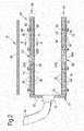
- the combustion section 18 comprises an annular combustion chamber 42, which is shown more clearly in figure 2 .
- the annular combustion chamber 42 has a radially inner annular wall 44, a radially outer annular wall 46 and an upstream end wall 48 connecting the upstream ends of the radially inner annular wall 44 and the radially outer annular wall 46.
- the annular combustion chamber 42 is surrounded by a casing 50.
- the upstream end wall 48 has a plurality of circumferentially spaced fuel injector apertures 52 and each fuel injector aperture 52 has a respective one of a plurality of fuel injectors 54.
- the upstream end wall 48 also has a plurality of smaller diameter cooling apertures 56 through which a flow of coolant is arranged to flow in operation.
- the radially inner annular wall 44 has a plurality of circumferentially spaced dilution apertures 58 through which a flow of dilution air is arranged to flow into the annular combustion chamber 42 in operation.
- the radially inner annular wall 44 also has a plurality of smaller diameter cooling apertures 60 through which a flow of coolant is arranged to flow in operation.
- the radially outer annular wall 46 has a plurality of circumferentially spaced dilution apertures 62 through which a flow of dilution air is arranged to flow into the annular combustion chamber 42 in operation.
- the radially outer annular wall 46 also has a plurality of smaller diameter cooling apertures 64 through which a flow of coolant is arranged to flow in operation.
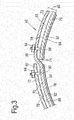
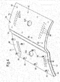
- the radially inner annular wall 44 and the radially outer annular wall 46 each comprise a plurality of segments 70 and 70' respectively, as seen more clearly in figures 3 , 4 and 5 .
- Each segment 70, 70' comprises a first portion 72, a second portion 74 and a third portion 76.
- the first portion 72 of each segment 70 extends circumferentially
- the third portion 76 of each segment 70, 70' extends circumferentially
- the second portion 74 of each segment 70, 70' extends radially to connect the first portion 72 and third portion 76 of the segment 70, 70' together.
- the segments 70, 70' are arranged such that the first portion 72 of each segment 70, 70' overlaps the third portion 76 of an adjacent segment 70, 70' and the first portion 72 of each segment 70, 70' is joined to the third portion 76 of the adjacent segment 70, 70'.
- the second portion 74 of each segment 70, 70' in fact extends circumferentially and radially in this example as shown in figures 3 , 4 and 5 .
- the first portion 72 of each segment 70, 70' is spaced radially from the third portion 76 of the adjacent segment 70, 70' to form at least one chamber 78 and the chamber 78 is arranged to be supplied with a coolant.
- first portion 72, the second portion 74 and the third portion 76 of each segment 70 and 70' extends axially by the same axial distance and thus the whole of the axial length of the first portion 72 of each segment 70, 70' overlaps the whole of the axial length of the third portion 76 of an adjacent segment 70, 70'.
- Each segment 70, 70' may be arranged such that the segments 70, 70' have one or more steps axially along their length so as to progressively increase the volume of the annular combustion chamber 42 along its length in a downstream direction.
- first and third portions 72 and 76 of the segments 70, 70' may have one or more steps axially along their length, with the steps in a radially outward direction for the segments 70 and in a radially inward direction for the segments 70.
- Each segment 70, 70' extends the full axial length of the annular combustion chamber 42 as shown in the figures, but it may be possible to have a plurality of rows of segments 70, 70' to form the full axial length of the annular combustion chamber 42.
- the segments 70 are arranged such that the first portion 72 of each segment 70 is arranged radially outwardly of the third portion 76 of the adjacent segment 70.
- the third portion 76 of each segment 70 has at least one radially outwardly extending stud 80 arranged to locate in a corresponding aperture 82 in the first portion 72 of the adjacent segment 70 to join the segments 70 together.
- the third portion 76 of each segment 70 has a plurality of radially outwardly extending studs 80 arranged to locate in a corresponding aperture 82 of a plurality of apertures 82 in the first portion 72 of the adjacent segment 70 to join the segments 70 together.
- the studs 80 are threaded into nuts 84 at the radially outer surface 86 of the first portion 72 of the adjacent segment 70.
- the segments 70 are arranged such that the first portion 72 of each segment 70 is arranged to extend circumferentially through substantially the same angle as the third portion 76 of the adjacent segment 70.
- a small gap is provided between the second portion 74 of each segment 70 and the end of the third portion 76 remote from the second portion 74 of the adjacent segment 70 to allow for thermal expansion and there may be a flow of cooling air through this gap.
- each segment 70 in fact extends circumferentially and radially.
- the first portion 72 of each segment 70 is spaced radially from the third portion 76 of the adjacent segment 70 to form at least one chamber 78 and the chamber 78 is arranged to be supplied with a coolant.
- the first portion 72 of each segment 70 has at least one dilution aperture 62A aligned with a corresponding dilution aperture 62B in the third portion 76 of the adjacent segment 70.
- the first portion 72 of each segment 70 has a plurality of cooling holes 86 arranged to supply coolant to the at least one chamber 78 defined between the first portion 72 and the third portion 76 of the adjacent segments 70.
- the plurality of cooling holes 86 may be arranged to impinge the coolant upon a radially outer surface 88 of the third portion 76 of the adjacent segment 70.
- the third portion 76 of each segment 70 has a plurality of effusion cooling holes 90 to provide a film of coolant on a radially inner surface 92 of the third portion 76 of each segment 70.
- the third portion 76 of each segment 70 may have a thermal barrier coating 94 on the radially inner surface 92.
- radially outwardly extending pedestals may be provided on the third portions 76 of each segment 70.
- the segments 70' are arranged such that the first portion 72 of each segment 70' is arranged radially inwardly of the third portion 76 of the adjacent segment 70'.
- the third portion 76 of each segment 70' has at least one radially inwardly extending stud 80 arranged to locate in a corresponding aperture 82 in the first portion 72 of the adjacent segment 70' to join the segments 70' together.
- the third portion 76 of each segment 70' has a plurality of radially inwardly extending studs 80 arranged to locate in a corresponding aperture 82 of a plurality of apertures 82 in the first portion 72 of the adjacent segment 70' to join the segments 70' together.
- the studs 80 are threaded into nuts 84 at the radially inner surface 86' of the first portion 72 of the adjacent segment 70'.
- the segments 70' are arranged such that the first portion 72 of each segment 70' is arranged to extend circumferentially through substantially the same angle as the third portion 76 of the adjacent segment 70'.
- a small gap is provided between the second portion 74 of each segment 70' and the end of the third portion 76 remote from the second portion 74 of the adjacent segment 70' to allow for thermal expansion and there may be a flow of cooling air through this gap.
- each segment 70' in fact extends circumferentially and radially.
- the first portion 72 of each segment 70' is spaced radially from the third portion 76 of the adjacent segment 70' to form at least one chamber 78 and the chamber 78 is arranged to be supplied with a coolant.
- the first portion 72 of each segment 70' has at least one dilution aperture 58A aligned with a corresponding dilution aperture 58B in the third portion 76 of the adjacent segment 70'.
- the first portion 72 of each segment 70' has a plurality of cooling holes 86 arranged to supply coolant to the at least one chamber 78 defined between the first portion 72 and the third portion 76 of the adjacent segments 70'.
- the plurality of cooling holes 86 are arranged to impinge the coolant upon a radially inner surface 88' of the third portion 76 of the adjacent segment 70'.
- the third portion 76 of each segment 70' has a plurality of effusion cooling holes 90' to provide a film of coolant on a radially outer surface 92' of the third portion 76 of each segment 70'.
- the third portion 76 of each segment 70' may have a thermal barrier coating 94 on a radially outer surface 92'.
- radially inwardly extending pedestals may be provided on the third portions 76 of each segment 70'.
- each segment 70 or 70' is formed integrally.
- At least one of the segments 70 or 70' is a casting and formed by casting in a mould and in an example all of the segments 70 and 70' are metal castings.
- at least one of the segments 70 or 70' is formed by direct laser deposition of a metal powder or selective laser sintering of a metal powder and in a further example all of the segments are formed by direct laser deposition of a metal powder or selective laser sintering of a metal powder.
- the segments 70 and 70' may be formed by other suitable methods.
- the radially outer annular wall 46 and the radially inner annular wall 44 may be bolted to the upstream end wall 48.
- the second portions 74 of the segments 70 and 70' have been described as extending radially and circumferentially, however, the second portions 74 may extend simply radially.
- all the segments may be identical and the first and third portions extend circumferentially through the same angle such that each segment defines a sector with a predetermined angle.
- the segments may be different with adjacent segments arranged such that the first portion of a first segment extends circumferentially through the same angle as the third portion of a second adjacent segment but the first portion of each segment extends circumferentially through a different angle to the third portion of that segment.
- the advantage of the present invention is that it allows the combustion chamber to be manufactured simply by bolting together a plurality of segments together, e.g. bolting a kit of parts together.
- the resulting combustion chamber is a double wall combustion chamber.
- the segments are simply cast from a suitable metal, or alloy, formed by direct laser deposition (DLD) of a powder metal, or alloy, or selective laser sintering of a powder metal, or alloy, for example a nickel base superalloy.
- the segments may be cast to provide one or more of the known cooling techniques, e.g. pedestals, turbulators, impingement cooling holes, effusion cooling holes.
- the segments of the combustor are replaceable in service without the need to use joining processes such as welding, brazing etc and damaged segments are simply un-bolted from the wall of the combustion chamber and a new, or replacement, segment is bolted into the wall of the combustion chamber.
- the present invention provides a combustion chamber in which one or more of the walls comprises a plurality of segments and each of the segments comprises a first portion which forms a portion of the cold wall of a double wall combustion chamber and a second portion which forms a portion of the hot wall of the double wall combustion chamber.
- the present invention enables the combustion chamber to be constructed from hand tools. There is a reduction in the lead time, a reduction in cost, no machine tools required, no forgings required, no sheet metal forming processes and repair is easier.
- the present invention has been described with reference to an annular combustion chamber, the present invention is equally applicable to a tubular combustion chamber and the tubular wall of the tubular combustion chamber is formed from a plurality of segments as described above.
- the radially inner annular wall and the radially outer annular wall are rings and define an annular combustion zone and in the case of a tubular combustion chamber the tubular wall is a ring and defines a cylindrical combustion zone.
Landscapes
- Engineering & Computer Science (AREA)
- Chemical & Material Sciences (AREA)
- Combustion & Propulsion (AREA)
- Mechanical Engineering (AREA)
- General Engineering & Computer Science (AREA)
- Turbine Rotor Nozzle Sealing (AREA)
- Cylinder Crankcases Of Internal Combustion Engines (AREA)
- Combustion Methods Of Internal-Combustion Engines (AREA)
Abstract
Description
- The present invention relates to a combustion chamber and in particular to a gas turbine engine combustion chamber.
- Conventionally an annular combustion chamber comprises an inner annular wall secured to an upstream end wall and an outer annular wall secured to the upstream end wall. The upstream end wall is conventionally formed by casting and machining. The inner and outer annular walls are conventionally formed by machining ring rolled forgings. Tiles are secured to the inner and outer walls and heat shields are secured to the upstream end wall.
- The conventional method of manufacturing an annular combustion chamber is expensive and has long lead times. The conventional method of manufacturing an annular combustion chamber requires many different manufacturing techniques, e.g. casting, forging, rolling, machining and welding etc.
- Accordingly the present invention seeks to provide a novel combustion chamber which reduces, preferably overcomes, the above mentioned problems.
- Accordingly the present invention provides a combustion chamber comprising at least one annular wall, the annular wall comprising a plurality of segments, each segment having a first portion, a second portion and a third portion, the first portion of each segment extending circumferentially, the third portion of each segment extending circumferentially and the second portion of each segment extending radially to connect the first portion and third portion of the segment, the segments being arranged such that the first portion of each segment overlaps the third portion of an adjacent segment and the first portion of each segment is joined to the third portion of the adjacent segment.
- The second portion of each segment may extend circumferentially and radially.
- The first portion of each segment may be spaced radially from the third portion of the adjacent segment to form at least one chamber and the chamber is arranged to be supplied with a coolant.
- The segment may be arranged such that the first portion of each segment is arranged radially outwardly of the third portion of the adjacent segment.
- The third portion of each segment may have at least one radially outwardly extending stud arranged to locate in a corresponding aperture in the first portion of the adjacent segment to join the segments together.
- The third portion of each segment may have a plurality of radially outwardly extending studs arranged to locate in a corresponding aperture of a plurality of apertures in the first portion of the adjacent segment to join the segments together.
- The studs may be threaded into nuts at the radially outer surface of the first portion of the adjacent segment.
- The first portion of each segment may have at least one dilution aperture aligned with a corresponding dilution aperture in the third portion of the adjacent segment.
- The first portion of each segment may have a plurality of cooling holes arranged to supply coolant to the at least one chamber defined between the first portion and the third portion of the adjacent segment.
- The plurality of cooling holes may be arranged to impinge the coolant upon a radially outer surface of the third portion of the adjacent segment.
- The third portion of each segment may have a plurality of effusion cooling apertures to provide a film of coolant on a radially inner surface of the third portion of each segment.
- The third portion of each segment may have a thermal barrier coating on a radially inner surface.
- The segment may be arranged such that the first portion of each segment is arranged radially inwardly of the third portion of the adjacent segment.
- The third portion of each segment may have at least one radially inwardly extending stud arranged to locate in a corresponding aperture in the first portion of the adjacent segment to join the segments together.
- The third portion of each segment may have a plurality of radially inwardly extending studs arranged to locate in a corresponding aperture of a plurality of apertures in the first portion of the adjacent segment to join the segments together.
- The studs may be threaded into nuts at the radially inner surface of the first portion of the adjacent segment.
- The first portion of each segment may have at least one dilution aperture aligned with a corresponding dilution aperture in the third portion of the adjacent segment.
- The first portion of each segment may have a plurality of cooling holes arranged to supply coolant to the at least one chamber defined between the first portion and the third portion of the adjacent segment.
- The plurality of cooling holes may be arranged to impinge the coolant upon a radially inner surface of the third portion of the adjacent segment.
- The third portion of each segment may have a plurality of effusion cooling apertures to provide a film of coolant on a radially outer surface of the third portion of each segment.
- The third portion of each segment may have a thermal barrier coating on a radially outer surface.
- The first portion, the second portion and the third portion of each segment may be formed integrally. At least one of the segments may be a casting. Each of the segments may comprise a casting. Each of the segments may be formed by direct laser deposition or selected laser sintering.
- The combustion chamber may be a tubular combustion chamber and the at least one wall is a tubular wall.
- The combustion chamber may be an annular combustion chamber and the at least one wall may be a radially outer annular wall or a radially inner annular wall.
- The combustion chamber may be a gas turbine engine combustion chamber.
- The present invention will be more fully described by way of example with reference to the accompanying drawings, in which:-
-
Figure 1 is a cross-sectional view through a turbofan gas turbine engine having an annular combustion chamber according to the present invention. -
Figure 2 is an enlarged cross-sectional view through an annular combustion chamber according to the present invention. -
Figure 3 is a cross-sectional view along line A-A infigure 2 . -
Figure 4 is an enlarged perspective view of a single segment of a radially outer annular wall of the annular combustion shown infigure 2 . -
Figure 5 is an enlarged perspective view of a pair of adjacent segments of a radially outer annular wall of the annular combustion chamber shown infigure 2 . - A turbofan
gas turbine engine 10, as shown infigure 1 , comprises in flow series aninlet 12, afan section 14, acompressor section 16, acombustion section 18, aturbine section 20 and anexhaust 22. Thefan section 14 comprises afan 24. Thecompressor section 16 comprises in flow series anintermediate pressure compressor 26 and ahigh pressure compressor 28. Theturbine section 20 comprises in flow series ahigh pressure turbine 30, anintermediate pressure turbine 32 and alow pressure turbine 34. Thefan 24 is driven by thelow pressure turbine 34 via ashaft 40. Theintermediate pressure compressor 26 is driven by theintermediate pressure turbine 32 via ashaft 38 and thehigh pressure compressor 28 is driven by thehigh pressure turbine 30 via ashaft 36. The turbofangas turbine engine 10 operates quite conventionally and its operation will not be discussed further. The turbofangas turbine engine 10 has a rotational axis X. - The
combustion section 18 comprises anannular combustion chamber 42, which is shown more clearly infigure 2 . Theannular combustion chamber 42 has a radially innerannular wall 44, a radially outerannular wall 46 and anupstream end wall 48 connecting the upstream ends of the radially innerannular wall 44 and the radially outerannular wall 46. Theannular combustion chamber 42 is surrounded by acasing 50. Theupstream end wall 48 has a plurality of circumferentially spacedfuel injector apertures 52 and eachfuel injector aperture 52 has a respective one of a plurality offuel injectors 54. Theupstream end wall 48 also has a plurality of smallerdiameter cooling apertures 56 through which a flow of coolant is arranged to flow in operation. The radially innerannular wall 44 has a plurality of circumferentially spaceddilution apertures 58 through which a flow of dilution air is arranged to flow into theannular combustion chamber 42 in operation. The radially innerannular wall 44 also has a plurality of smallerdiameter cooling apertures 60 through which a flow of coolant is arranged to flow in operation. The radially outerannular wall 46 has a plurality of circumferentially spaceddilution apertures 62 through which a flow of dilution air is arranged to flow into theannular combustion chamber 42 in operation. The radially outerannular wall 46 also has a plurality of smallerdiameter cooling apertures 64 through which a flow of coolant is arranged to flow in operation. - The radially inner
annular wall 44 and the radially outerannular wall 46 each comprise a plurality ofsegments 70 and 70' respectively, as seen more clearly infigures 3 ,4 and5 . Eachsegment 70, 70' comprises afirst portion 72, asecond portion 74 and athird portion 76. Thefirst portion 72 of eachsegment 70 extends circumferentially, thethird portion 76 of eachsegment 70, 70' extends circumferentially and thesecond portion 74 of eachsegment 70, 70' extends radially to connect thefirst portion 72 andthird portion 76 of thesegment 70, 70' together. Thesegments 70, 70' are arranged such that thefirst portion 72 of eachsegment 70, 70' overlaps thethird portion 76 of anadjacent segment 70, 70' and thefirst portion 72 of eachsegment 70, 70' is joined to thethird portion 76 of theadjacent segment 70, 70'. Thesecond portion 74 of eachsegment 70, 70' in fact extends circumferentially and radially in this example as shown infigures 3 ,4 and5 . Thefirst portion 72 of eachsegment 70, 70' is spaced radially from thethird portion 76 of theadjacent segment 70, 70' to form at least onechamber 78 and thechamber 78 is arranged to be supplied with a coolant. - It is to be noted that the
first portion 72, thesecond portion 74 and thethird portion 76 of eachsegment 70 and 70' extends axially by the same axial distance and thus the whole of the axial length of thefirst portion 72 of eachsegment 70, 70' overlaps the whole of the axial length of thethird portion 76 of anadjacent segment 70, 70'. Eachsegment 70, 70' may be arranged such that thesegments 70, 70' have one or more steps axially along their length so as to progressively increase the volume of theannular combustion chamber 42 along its length in a downstream direction. Thus, the first andthird portions segments 70, 70' may have one or more steps axially along their length, with the steps in a radially outward direction for thesegments 70 and in a radially inward direction for thesegments 70. Eachsegment 70, 70' extends the full axial length of theannular combustion chamber 42 as shown in the figures, but it may be possible to have a plurality of rows ofsegments 70, 70' to form the full axial length of theannular combustion chamber 42. - In the case of the radially outer
annular wall 46, thesegments 70 are arranged such that thefirst portion 72 of eachsegment 70 is arranged radially outwardly of thethird portion 76 of theadjacent segment 70. Thethird portion 76 of eachsegment 70 has at least one radially outwardly extendingstud 80 arranged to locate in a correspondingaperture 82 in thefirst portion 72 of theadjacent segment 70 to join thesegments 70 together. Thethird portion 76 of eachsegment 70 has a plurality of radially outwardly extendingstuds 80 arranged to locate in a correspondingaperture 82 of a plurality ofapertures 82 in thefirst portion 72 of theadjacent segment 70 to join thesegments 70 together. Thestuds 80 are threaded intonuts 84 at the radiallyouter surface 86 of thefirst portion 72 of theadjacent segment 70. In the case of the radially outerannular wall 46, thesegments 70 are arranged such that thefirst portion 72 of eachsegment 70 is arranged to extend circumferentially through substantially the same angle as thethird portion 76 of theadjacent segment 70. A small gap is provided between thesecond portion 74 of eachsegment 70 and the end of thethird portion 76 remote from thesecond portion 74 of theadjacent segment 70 to allow for thermal expansion and there may be a flow of cooling air through this gap. - The
second portion 74 of eachsegment 70 in fact extends circumferentially and radially. Thefirst portion 72 of eachsegment 70 is spaced radially from thethird portion 76 of theadjacent segment 70 to form at least onechamber 78 and thechamber 78 is arranged to be supplied with a coolant. - The
first portion 72 of eachsegment 70 has at least onedilution aperture 62A aligned with a correspondingdilution aperture 62B in thethird portion 76 of theadjacent segment 70. Thefirst portion 72 of eachsegment 70 has a plurality of cooling holes 86 arranged to supply coolant to the at least onechamber 78 defined between thefirst portion 72 and thethird portion 76 of theadjacent segments 70. The plurality of cooling holes 86 may be arranged to impinge the coolant upon a radiallyouter surface 88 of thethird portion 76 of theadjacent segment 70. Thethird portion 76 of eachsegment 70 has a plurality of effusion cooling holes 90 to provide a film of coolant on a radiallyinner surface 92 of thethird portion 76 of eachsegment 70. Thethird portion 76 of eachsegment 70 may have athermal barrier coating 94 on the radiallyinner surface 92. - In addition radially outwardly extending pedestals may be provided on the
third portions 76 of eachsegment 70. - In the case of the radially inner
annular wall 44, the segments 70' are arranged such that thefirst portion 72 of each segment 70' is arranged radially inwardly of thethird portion 76 of the adjacent segment 70'. Thethird portion 76 of each segment 70' has at least one radially inwardly extendingstud 80 arranged to locate in a correspondingaperture 82 in thefirst portion 72 of the adjacent segment 70' to join the segments 70' together. Thethird portion 76 of each segment 70' has a plurality of radially inwardly extendingstuds 80 arranged to locate in a correspondingaperture 82 of a plurality ofapertures 82 in thefirst portion 72 of the adjacent segment 70' to join the segments 70' together. Thestuds 80 are threaded intonuts 84 at the radially inner surface 86' of thefirst portion 72 of the adjacent segment 70'. In the case of the radially innerannular wall 44, the segments 70' are arranged such that thefirst portion 72 of each segment 70' is arranged to extend circumferentially through substantially the same angle as thethird portion 76 of the adjacent segment 70'. A small gap is provided between thesecond portion 74 of each segment 70' and the end of thethird portion 76 remote from thesecond portion 74 of the adjacent segment 70' to allow for thermal expansion and there may be a flow of cooling air through this gap. - The
second portion 74 of each segment 70' in fact extends circumferentially and radially. Thefirst portion 72 of each segment 70' is spaced radially from thethird portion 76 of the adjacent segment 70' to form at least onechamber 78 and thechamber 78 is arranged to be supplied with a coolant. - The
first portion 72 of each segment 70' has at least onedilution aperture 58A aligned with a correspondingdilution aperture 58B in thethird portion 76 of the adjacent segment 70'. Thefirst portion 72 of each segment 70' has a plurality of cooling holes 86 arranged to supply coolant to the at least onechamber 78 defined between thefirst portion 72 and thethird portion 76 of the adjacent segments 70'. The plurality of cooling holes 86 are arranged to impinge the coolant upon a radially inner surface 88' of thethird portion 76 of the adjacent segment 70'. Thethird portion 76 of each segment 70' has a plurality of effusion cooling holes 90' to provide a film of coolant on a radially outer surface 92' of thethird portion 76 of each segment 70'. Thethird portion 76 of each segment 70' may have athermal barrier coating 94 on a radially outer surface 92'. In addition radially inwardly extending pedestals may be provided on thethird portions 76 of each segment 70'. - The
first portion 72, thesecond portion 74 and thethird portion 76 of eachsegment 70 or 70' is formed integrally. At least one of thesegments 70 or 70' is a casting and formed by casting in a mould and in an example all of thesegments 70 and 70' are metal castings. Alternatively at least one of thesegments 70 or 70' is formed by direct laser deposition of a metal powder or selective laser sintering of a metal powder and in a further example all of the segments are formed by direct laser deposition of a metal powder or selective laser sintering of a metal powder. Thesegments 70 and 70' may be formed by other suitable methods. - The radially outer
annular wall 46 and the radially innerannular wall 44 may be bolted to theupstream end wall 48. In the figures thesecond portions 74 of thesegments 70 and 70' have been described as extending radially and circumferentially, however, thesecond portions 74 may extend simply radially. - Thus all the segments may be identical and the first and third portions extend circumferentially through the same angle such that each segment defines a sector with a predetermined angle. For example there may be two, three, four, six, eight or twelve or other suitable numbers of segments defining a half, a third, a quarter, a sixth or a twelfth of the combustion chamber. Alternatively, the segments may be different with adjacent segments arranged such that the first portion of a first segment extends circumferentially through the same angle as the third portion of a second adjacent segment but the first portion of each segment extends circumferentially through a different angle to the third portion of that segment.
- The advantage of the present invention is that it allows the combustion chamber to be manufactured simply by bolting together a plurality of segments together, e.g. bolting a kit of parts together. The resulting combustion chamber is a double wall combustion chamber. The segments are simply cast from a suitable metal, or alloy, formed by direct laser deposition (DLD) of a powder metal, or alloy, or selective laser sintering of a powder metal, or alloy, for example a nickel base superalloy. The segments may be cast to provide one or more of the known cooling techniques, e.g. pedestals, turbulators, impingement cooling holes, effusion cooling holes. The segments of the combustor are replaceable in service without the need to use joining processes such as welding, brazing etc and damaged segments are simply un-bolted from the wall of the combustion chamber and a new, or replacement, segment is bolted into the wall of the combustion chamber. The present invention provides a combustion chamber in which one or more of the walls comprises a plurality of segments and each of the segments comprises a first portion which forms a portion of the cold wall of a double wall combustion chamber and a second portion which forms a portion of the hot wall of the double wall combustion chamber. The present invention enables the combustion chamber to be constructed from hand tools. There is a reduction in the lead time, a reduction in cost, no machine tools required, no forgings required, no sheet metal forming processes and repair is easier.
- Although the present invention has been described with reference to an annular combustion chamber, the present invention is equally applicable to a tubular combustion chamber and the tubular wall of the tubular combustion chamber is formed from a plurality of segments as described above. In the case of an annular combustion chamber the radially inner annular wall and the radially outer annular wall are rings and define an annular combustion zone and in the case of a tubular combustion chamber the tubular wall is a ring and defines a cylindrical combustion zone.
- Although the present invention has been described with reference to a gas turbine engine combustion chamber, the present invention is equally applicable to other types of combustion chambers.
Claims (16)
- A combustion chamber (42) comprising at least one annular wall (44,46), characterised in that the annular wall (44,46) comprising a plurality of segments (70,70'), each segment (70,70') having a first portion (72), a second portion (74) and a third portion (76), the first portion (72) of each segment (70,70') extending circumferentially, the third portion (76) of each segment (70,70') extending circumferentially and the second portion (74) of each segment (70,70') extending radially to connect the first portion (72) and third portion (76) of the segment (70,70'), the segments (70,70') being arranged such that the first portion (72) of each segment (70,70') overlaps the third portion (76) of an adjacent segment (70,70') and the first portion (72) of each segment (70,70') is joined to the third portion (76) of the adjacent segment (70,70').
- A combustion chamber as claimed in claim 1 wherein the second portion (74) of each segment (70,70') extends circumferentially and radially.
- A combustion chamber as claimed in claim 1 or claim 2 wherein the first portion (72) of each segment (70,70') is spaced radially from the third portion (76) of the adjacent segment (70,70') to form at least one chamber (78) and the chamber (78) is arranged to be supplied with a coolant.
- A combustion chamber as claimed in claim 1, claim 2 or claim 3 wherein the segment (70) is arranged such that the first portion (72) of each segment (70) is arranged radially outwardly of the third portion (76) of the adjacent segment (70).
- A combustion chamber as claimed in claim 4 wherein the third portion (76) of each segment (70) has a plurality of radially outwardly extending studs (80) arranged to locate in a corresponding aperture (82) of a plurality of apertures (82) in the first portion (72) of the adjacent segment (70) to join the segments (70) together.
- A combustion chamber as claimed in claim 1, claim 2 or claim 3 wherein the segment (70') is arranged such that the first portion (72) of each segment (70') is arranged radially inwardly of the third portion (76) of the adjacent segment (70').
- A combustion chamber as claimed in claim 6 wherein the third portion (76) of each segment (70') has a plurality of radially inwardly extending studs (80) arranged to locate in a corresponding aperture (82) of a plurality of apertures (82) in the first portion (72) of the adjacent segment (70') to join the segments (70') together.
- A combustion chamber as claimed in any of claims 1 to 7 wherein the first portion (72) of each segment (70,70') has at least one dilution aperture (62A) aligned with a corresponding dilution aperture (62B) in the third portion (76) of the adjacent segment (70,70').
- A combustion chamber as claimed in any of claims 3 to 8 wherein the first portion (72) of each segment (70,70') has a plurality of cooling holes (86) arranged to supply coolant to the at least one chamber (78) defined between the first portion (72) and the third portion (76) of the adjacent segment (70,70').
- A combustion chamber as claimed in claim 9 wherein the plurality of cooling holes (86) are arranged to impinge the coolant upon a radially outer surface (88) of the third portion (76) of the adjacent segment (70) or the plurality of cooling holes (86) are arranged to impinge the coolant upon a radially inner surface (88') of the third portion (76) of the adjacent segment (70').
- A combustion chamber as claimed in any of claims 3 to 10 wherein the third portion (76) of each segment (70) has a plurality of effusion cooling apertures (90) to provide a film of coolant on a radially inner surface (92) of the third portion (76) of each segment (70) or the third portion (76) of each segment (70') has a plurality of effusion cooling apertures (90) to provide a film of coolant on a radially outer surface (92') of the third portion (76) of each segment (70').
- A combustion chamber as claimed in any of claims 3 to 11 wherein the third portion (76) of each segment (70) has a thermal barrier coating (94) on a radially inner surface (92) or the third portion (76) of each segment (70') has a thermal barrier coating (94) on a radially outer surface (92').
- A combustion chamber as claimed in any of claims 1 to 12 wherein the first portion (72), the second portion (74) and the third portion (76) of each segment (70,70') is formed integrally.
- A combustion chamber as claimed in claim 13 wherein at least one of the segments (70,70') comprises a casting.
- A combustion chamber as claimed in any of claims 1 to 14 wherein the combustion chamber is a tubular combustion chamber and the at least one wall is a tubular wall or the combustion chamber is an annular combustion chamber and the at least one wall is a radially outer annular wall or the combustion chamber is an annular combustion chamber and the at least one wall is a radially inner annular wall.
- A combustion chamber as claimed in any of claims 1 to 15 wherein the combustion chamber (42) is a gas turbine engine combustion chamber.
Applications Claiming Priority (1)
| Application Number | Priority Date | Filing Date | Title |
|---|---|---|---|
| GBGB1113249.5A GB201113249D0 (en) | 2011-08-02 | 2011-08-02 | A combustion chamber |
Publications (2)
| Publication Number | Publication Date |
|---|---|
| EP2554903A2 true EP2554903A2 (en) | 2013-02-06 |
| EP2554903A3 EP2554903A3 (en) | 2017-11-01 |
Family
ID=44676544
Family Applications (1)
| Application Number | Title | Priority Date | Filing Date |
|---|---|---|---|
| EP12176502.8A Withdrawn EP2554903A3 (en) | 2011-08-02 | 2012-07-16 | A combustion chamber |
Country Status (3)
| Country | Link |
|---|---|
| US (1) | US8707706B2 (en) |
| EP (1) | EP2554903A3 (en) |
| GB (1) | GB201113249D0 (en) |
Cited By (5)
| Publication number | Priority date | Publication date | Assignee | Title |
|---|---|---|---|---|
| EP2871418A1 (en) * | 2013-11-11 | 2015-05-13 | Rolls-Royce Deutschland Ltd & Co KG | Gas turbine combustion chamber and method for its manufacture |
| EP2978941A4 (en) * | 2013-03-26 | 2016-03-23 | United Technologies Corp | TURBINE ENGINE AND TURBINE ENGINE COMPONENT HAVING IMPROVED COOLING FEET |
| EP3066391A4 (en) * | 2013-11-05 | 2017-06-21 | United Technologies Corporation | Cooled combustor floatwall panel |
| EP3058196A4 (en) * | 2013-10-18 | 2017-10-11 | United Technologies Corporation | Panel with cooling holes and methods for fabricating same |
| US10502421B2 (en) | 2015-02-04 | 2019-12-10 | Rolls-Royce Plc | Combustion chamber and a combustion chamber segment |
Families Citing this family (12)
| Publication number | Priority date | Publication date | Assignee | Title |
|---|---|---|---|---|
| WO2014200588A2 (en) * | 2013-03-14 | 2014-12-18 | United Technologies Corporation | Additive manufactured gas turbine engine combustor liner panel |
| DE102014204468A1 (en) * | 2014-03-11 | 2015-10-01 | Rolls-Royce Deutschland Ltd & Co Kg | Gas turbine combustor and method for its production |
| US20170167729A1 (en) * | 2014-07-30 | 2017-06-15 | Siemens Aktiengesellschaft | Multiple feed platefins within a hot gas path cooling system in a combustor basket in a combustion turbine engine |
| GB201417429D0 (en) * | 2014-10-02 | 2014-11-19 | Rolls Royce Plc | A cooled component |
| US10451281B2 (en) | 2014-11-04 | 2019-10-22 | United Technologies Corporation | Low lump mass combustor wall with quench aperture(s) |
| EP3048370A1 (en) * | 2015-01-23 | 2016-07-27 | Siemens Aktiengesellschaft | Combustion chamber for a gas turbine engine |
| EP3130854B1 (en) * | 2015-08-13 | 2020-06-24 | Pratt & Whitney Canada Corp. | Combustor shape cooling system |
| US10876730B2 (en) * | 2016-02-25 | 2020-12-29 | Pratt & Whitney Canada Corp. | Combustor primary zone cooling flow scheme |
| GB201613208D0 (en) * | 2016-08-01 | 2016-09-14 | Rolls Royce Plc | A combustion chamber assembly and a combustion chamber segment |
| US10386067B2 (en) * | 2016-09-15 | 2019-08-20 | United Technologies Corporation | Wall panel assembly for a gas turbine engine |
| FR3069908B1 (en) * | 2017-08-02 | 2021-09-24 | Safran Aircraft Engines | ANNULAR COMBUSTION CHAMBER |
| US12601483B2 (en) * | 2023-12-29 | 2026-04-14 | Ge Infrastructure Technology Llc | Additively manufactured combustion liner and axial fuel stage injector |
Family Cites Families (7)
| Publication number | Priority date | Publication date | Assignee | Title |
|---|---|---|---|---|
| US2699648A (en) * | 1950-10-03 | 1955-01-18 | Gen Electric | Combustor sectional liner structure with annular inlet nozzles |
| US3496722A (en) * | 1968-08-02 | 1970-02-24 | Garrett Corp | Combustion chamber flame tube construction |
| US4414816A (en) | 1980-04-02 | 1983-11-15 | The United States Of America As Represented By The Administrator Of The National Aeronautics And Space Administration | Combustor liner construction |
| GB2087065B (en) | 1980-11-08 | 1984-11-07 | Rolls Royce | Wall structure for a combustion chamber |
| US4688310A (en) | 1983-12-19 | 1987-08-25 | General Electric Company | Fabricated liner article and method |
| US4628694A (en) | 1983-12-19 | 1986-12-16 | General Electric Company | Fabricated liner article and method |
| FR2714152B1 (en) * | 1993-12-22 | 1996-01-19 | Snecma | Device for fixing a thermal protection tile in a combustion chamber. |
-
2011
- 2011-08-02 GB GBGB1113249.5A patent/GB201113249D0/en not_active Ceased
-
2012
- 2012-07-16 EP EP12176502.8A patent/EP2554903A3/en not_active Withdrawn
- 2012-07-16 US US13/549,830 patent/US8707706B2/en active Active
Non-Patent Citations (1)
| Title |
|---|
| None |
Cited By (7)
| Publication number | Priority date | Publication date | Assignee | Title |
|---|---|---|---|---|
| EP2978941A4 (en) * | 2013-03-26 | 2016-03-23 | United Technologies Corp | TURBINE ENGINE AND TURBINE ENGINE COMPONENT HAVING IMPROVED COOLING FEET |
| EP3058196A4 (en) * | 2013-10-18 | 2017-10-11 | United Technologies Corporation | Panel with cooling holes and methods for fabricating same |
| EP3066391A4 (en) * | 2013-11-05 | 2017-06-21 | United Technologies Corporation | Cooled combustor floatwall panel |
| US10190773B2 (en) | 2013-11-05 | 2019-01-29 | United Technologies Corporation | Attachment stud on a combustor floatwall panel with internal cooling holes |
| EP2871418A1 (en) * | 2013-11-11 | 2015-05-13 | Rolls-Royce Deutschland Ltd & Co KG | Gas turbine combustion chamber and method for its manufacture |
| EP2871418B1 (en) | 2013-11-11 | 2015-10-21 | Rolls-Royce Deutschland Ltd & Co KG | Gas turbine combustion chamber and method for its manufacture |
| US10502421B2 (en) | 2015-02-04 | 2019-12-10 | Rolls-Royce Plc | Combustion chamber and a combustion chamber segment |
Also Published As
| Publication number | Publication date |
|---|---|
| US8707706B2 (en) | 2014-04-29 |
| GB201113249D0 (en) | 2011-09-14 |
| US20130031904A1 (en) | 2013-02-07 |
| EP2554903A3 (en) | 2017-11-01 |
Similar Documents
| Publication | Publication Date | Title |
|---|---|---|
| US8707706B2 (en) | Combustion chamber | |
| US10502421B2 (en) | Combustion chamber and a combustion chamber segment | |
| US11766722B2 (en) | Method for the hybrid construction of multi-piece parts | |
| EP2743585B1 (en) | A combustion chamber | |
| EP3006831B1 (en) | A cooled component | |
| EP2846097B1 (en) | A gas turbine combustion chamber with tiles having film cooling apertures | |
| US8408010B2 (en) | Combustor wall apparatus with parts joined by mechanical fasteners | |
| US10907830B2 (en) | Combustor chamber arrangement with sealing ring | |
| EP3236155B1 (en) | Combustion chamber with segmented wall | |
| US9950382B2 (en) | Method for a fabricated heat shield with rails and studs mounted on the cold side of a combustor heat shield | |
| US20160334102A1 (en) | Controlled-leak combustor grommet | |
| US20190024895A1 (en) | Combustor dilution structure for gas turbine engine | |
| EP2947390A1 (en) | A combustion chamber arrangement | |
| US10392945B2 (en) | Turbomachine cooling system | |
| JP2019035573A (en) | Spiral combustor for gas turbine engine | |
| EP3330486B1 (en) | Impingement insert for a gas turbine engine | |
| US20160115874A1 (en) | Liner grommet assembly | |
| US10690345B2 (en) | Combustor assemblies for use in turbine engines and methods of assembling same | |
| US11079111B2 (en) | Air tube | |
| US20140116056A1 (en) | Gas turbine diffuser with flow separator | |
| GB2491580A (en) | A method of manufacturing a sheet metal annular combustion chamber | |
| US20190024519A1 (en) | Turbomachine airfoil | |
| US20140183782A1 (en) | Mold assembly for forming a cast component and method of manufacturing a mold assembly |
Legal Events
| Date | Code | Title | Description |
|---|---|---|---|
| PUAI | Public reference made under article 153(3) epc to a published international application that has entered the european phase |
Free format text: ORIGINAL CODE: 0009012 |
|
| AK | Designated contracting states |
Kind code of ref document: A2 Designated state(s): AL AT BE BG CH CY CZ DE DK EE ES FI FR GB GR HR HU IE IS IT LI LT LU LV MC MK MT NL NO PL PT RO RS SE SI SK SM TR |
|
| AX | Request for extension of the european patent |
Extension state: BA ME |
|
| RAP1 | Party data changed (applicant data changed or rights of an application transferred) |
Owner name: ROLLS-ROYCE PLC |
|
| PUAL | Search report despatched |
Free format text: ORIGINAL CODE: 0009013 |
|
| AK | Designated contracting states |
Kind code of ref document: A3 Designated state(s): AL AT BE BG CH CY CZ DE DK EE ES FI FR GB GR HR HU IE IS IT LI LT LU LV MC MK MT NL NO PL PT RO RS SE SI SK SM TR |
|
| AX | Request for extension of the european patent |
Extension state: BA ME |
|
| RIC1 | Information provided on ipc code assigned before grant |
Ipc: F23R 3/06 20060101ALI20170927BHEP Ipc: F23R 3/00 20060101AFI20170927BHEP Ipc: F23R 3/60 20060101ALI20170927BHEP |
|
| STAA | Information on the status of an ep patent application or granted ep patent |
Free format text: STATUS: THE APPLICATION HAS BEEN PUBLISHED |
|
| STAA | Information on the status of an ep patent application or granted ep patent |
Free format text: STATUS: THE APPLICATION IS DEEMED TO BE WITHDRAWN |
|
| 18D | Application deemed to be withdrawn |
Effective date: 20180503 |