EP2554841A1 - A gearbox comprising a stationary gear component formed on the basis of variable flank profiles of gear teeth - Google Patents
A gearbox comprising a stationary gear component formed on the basis of variable flank profiles of gear teeth Download PDFInfo
- Publication number
- EP2554841A1 EP2554841A1 EP11006392A EP11006392A EP2554841A1 EP 2554841 A1 EP2554841 A1 EP 2554841A1 EP 11006392 A EP11006392 A EP 11006392A EP 11006392 A EP11006392 A EP 11006392A EP 2554841 A1 EP2554841 A1 EP 2554841A1
- Authority
- EP
- European Patent Office
- Prior art keywords
- gear
- teeth
- stationary
- tooth
- flank
- Prior art date
- Legal status (The legal status is an assumption and is not a legal conclusion. Google has not performed a legal analysis and makes no representation as to the accuracy of the status listed.)
- Granted
Links
Images






Classifications
-
- F—MECHANICAL ENGINEERING; LIGHTING; HEATING; WEAPONS; BLASTING
- F16—ENGINEERING ELEMENTS AND UNITS; GENERAL MEASURES FOR PRODUCING AND MAINTAINING EFFECTIVE FUNCTIONING OF MACHINES OR INSTALLATIONS; THERMAL INSULATION IN GENERAL
- F16H—GEARING
- F16H1/00—Toothed gearings for conveying rotary motion
- F16H1/28—Toothed gearings for conveying rotary motion with gears having orbital motion
- F16H1/2809—Toothed gearings for conveying rotary motion with gears having orbital motion with means for equalising the distribution of load on the planet gears
-
- B—PERFORMING OPERATIONS; TRANSPORTING
- B23—MACHINE TOOLS; METAL-WORKING NOT OTHERWISE PROVIDED FOR
- B23F—MAKING GEARS OR TOOTHED RACKS
- B23F19/00—Finishing gear teeth by other tools than those used for manufacturing gear teeth
- B23F19/002—Modifying the theoretical tooth flank form, e.g. crowning
-
- F—MECHANICAL ENGINEERING; LIGHTING; HEATING; WEAPONS; BLASTING
- F03—MACHINES OR ENGINES FOR LIQUIDS; WIND, SPRING, OR WEIGHT MOTORS; PRODUCING MECHANICAL POWER OR A REACTIVE PROPULSIVE THRUST, NOT OTHERWISE PROVIDED FOR
- F03D—WIND MOTORS
- F03D15/00—Transmission of mechanical power
-
- F—MECHANICAL ENGINEERING; LIGHTING; HEATING; WEAPONS; BLASTING
- F03—MACHINES OR ENGINES FOR LIQUIDS; WIND, SPRING, OR WEIGHT MOTORS; PRODUCING MECHANICAL POWER OR A REACTIVE PROPULSIVE THRUST, NOT OTHERWISE PROVIDED FOR
- F03D—WIND MOTORS
- F03D15/00—Transmission of mechanical power
- F03D15/10—Transmission of mechanical power using gearing not limited to rotary motion, e.g. with oscillating or reciprocating members
-
- F—MECHANICAL ENGINEERING; LIGHTING; HEATING; WEAPONS; BLASTING
- F16—ENGINEERING ELEMENTS AND UNITS; GENERAL MEASURES FOR PRODUCING AND MAINTAINING EFFECTIVE FUNCTIONING OF MACHINES OR INSTALLATIONS; THERMAL INSULATION IN GENERAL
- F16H—GEARING
- F16H55/00—Elements with teeth or friction surfaces for conveying motion; Worms, pulleys or sheaves for gearing mechanisms
- F16H55/02—Toothed members; Worms
- F16H55/08—Profiling
- F16H55/0806—Involute profile
-
- F—MECHANICAL ENGINEERING; LIGHTING; HEATING; WEAPONS; BLASTING
- F05—INDEXING SCHEMES RELATING TO ENGINES OR PUMPS IN VARIOUS SUBCLASSES OF CLASSES F01-F04
- F05B—INDEXING SCHEME RELATING TO WIND, SPRING, WEIGHT, INERTIA OR LIKE MOTORS, TO MACHINES OR ENGINES FOR LIQUIDS COVERED BY SUBCLASSES F03B, F03D AND F03G
- F05B2260/00—Function
- F05B2260/40—Transmission of power
- F05B2260/403—Transmission of power through the shape of the drive components
- F05B2260/4031—Transmission of power through the shape of the drive components as in toothed gearing
- F05B2260/40311—Transmission of power through the shape of the drive components as in toothed gearing of the epicyclic, planetary or differential type
-
- Y—GENERAL TAGGING OF NEW TECHNOLOGICAL DEVELOPMENTS; GENERAL TAGGING OF CROSS-SECTIONAL TECHNOLOGIES SPANNING OVER SEVERAL SECTIONS OF THE IPC; TECHNICAL SUBJECTS COVERED BY FORMER USPC CROSS-REFERENCE ART COLLECTIONS [XRACs] AND DIGESTS
- Y02—TECHNOLOGIES OR APPLICATIONS FOR MITIGATION OR ADAPTATION AGAINST CLIMATE CHANGE
- Y02E—REDUCTION OF GREENHOUSE GAS [GHG] EMISSIONS, RELATED TO ENERGY GENERATION, TRANSMISSION OR DISTRIBUTION
- Y02E10/00—Energy generation through renewable energy sources
- Y02E10/70—Wind energy
- Y02E10/72—Wind turbines with rotation axis in wind direction
Definitions
- the present invention relates to gear systems, such as planetary gears, in which superior load distribution may be achieved by applying a tooth trace correction on teeth of at least some components of the gearbox.
- the present invention relates to gearboxes that are configured to transmit high mechanical powers, such as gearboxes of wind power plants.
- the actually occurring mechanical pressure and thus the mechanical stress acting on the individual teeth significantly depends on the area or point or line of interaction, which in turn is affected by the overall profile of the teeth flanks.
- the mechanical efficiency, the noise generation, the duration and the like are important aspects that have to be addressed in order to comply with the requirements of the various applications.
- the engagement of the individual teeth of two gears can be adjusted so as to obtain an improvement in one or more of the above-mentioned aspects, for instance in view of noise reduction and the like, by appropriately adapting the flank profile of the teeth.
- tooth trace correction is applied during the fabrication of one or more gears of a gearbox in order to appropriately adapt the tooth flanks to the expected load condition during operation of the gear system.
- the leading flank of the teeth may be provided with a different profile compared to the trailing flank of the teeth, when substantially a predefined direction of rotation of the gears is encountered in the application under consideration.
- the process of tooth trace correction is thus a well-established concept for improving the load conditions for various components of the gearbox, for instance by applying appropriate additional manufacturing steps upon fabricating the individual gears of the gear system and/or by controlling the manufacturing process for the teeth, for instance the grinding process, in order to establish the teeth so as to have the desired target flank profile.
- a substantially balanced load distribution in complex gearboxes is an essential aspect when the gearbox is designed for transferring high mechanical powers.
- wind energy has proven to be one important component for providing alternative energy due to the superior availability of wind energy and the moderately high cost-effectiveness of modern wind power plants.
- most of the highly efficient wind turbines are designed on the basis of wind rotors supported by a substantially horizontal shaft that in turn is mechanically coupled to a gearbox in order to convert the moderately low rotation speed of the wind rotor into a desired high rotation speed of an electrical generator.
- the weight of the gearbox is typically reduced as much as possible in order to obtain a desired power-to-weight ratio, thereby necessitating the components of the gearbox to be dimensioned closely to the material fatigue limits.
- the gearboxes have to be operated in remote locations, possibly in sophisticated environmental conditions, for instance offshore, so that regular maintenance intervals may represent an important cost factor, which in turn significantly influences the overall profitability of the wind power plant. Consequently, manufacturers of planetary gear systems for wind turbines have to meet very different requirements, for instance increasing the power-to-weight ratio, which requires reducing the amounts of required materials for the various gears, and providing superior durability at a reduced number of maintenance events over the lifetime of the wind turbine.
- the latter aspect may, however, require superior materials or an increased amount of material for enhancing the mechanical strength of the various components and/or the application of superior manufacturing techniques, such as sophisticated tooth trace corrections in order to reduce any load variations that may occur in the individual components of the planetary gear system.
- a gearbox structure is used in wind power plants in which a stationary ring gear of the planetary system engages with the planetary wheel whose carrier in turn is mechanically coupled to the shaft that supports the wind rotor.
- the sun gear is typically mechanically connected to an output shaft of the planetary gear system, which in turn may be coupled to a further gear system or to an electric machine. Consequently, the significant diameter of the wind rotor in combination with typically varying wind conditions, in particular in sophisticated environments, may result in a pronounced variation of the load conditions acting on the planetary gear system. That is, the torque transferred from the wind rotor via the shaft into the planetary stage of the gearbox may finally result in corresponding varying load conditions for the stationary ring gear and the sun gear.
- the object is solved by a gearbox that comprises a stationary gear component having a plurality of teeth formed along a tooth trace. At least some of the plurality of teeth differ in their tooth flank profiles at least at an initial phase of the operational lifetime of the gearbox.
- the gearbox further comprises at least one rotary gear that is mechanically coupled to a subset of the teeth of the stationary gear component. It may prove advantageous when the tooth flank profiles of at least some teeth of the stationary gear component are individually adjusted. This may be accomplished by individually forming the teeth and/or by individually machining the teeth, the tooth flanks and/or the tooth flank profiles.
- the leading and/or trailing tooth flank profile of each tooth can be individually adjusted, preferably such that said tooth flank profile comprises geometrical variations along the axial direction of said stationary gear component.
- At least some teeth of the stationary gear component are provided along the tooth trace thereof so as to provide for varying tooth geometries.
- a difference in flank profile of a tooth or generally a difference in tooth geometry is to be understood such that at least a first tooth is provided along the tooth trace which has a first flank profile, ie. a leading flank and/or a trailing flank profile, that differs from the corresponding flank profile of a second tooth so that the first and second teeth are configured to be operated at different load conditions that may be encountered along the different locations along the tooth trace.
- the stationary gear component may be provided so as to have an appropriately adapted tooth profile depending on the location of a respective tooth along the tooth trace, which may thus allow for a superior load distribution.
- the variance in the tooth profile may be achieved by determining the stress conditions of the teeth depending on their position along the tooth trace and by appropriately adapting the shape or profiles of the tooth under consideration at the various locations of interest so that the adapted shape deviations and the torque induced by locally varying stress conditions may compensate each other or may at least be reduced. That is, in particular, any deviations or deflections of the teeth induced by torque forces varying along the tooth trace, such as the perimeter of ring gear and the like, or the length of a linear gear component, may be compensated for or may be at least significantly reduced for deviations caused by the rotary gear in a highly non-symmetric manner along the tooth trace.
- tooth flank profiles are individually adjusted as a function of at least one of the following parameters:
- the individual adjustment of the tooth flank profiles is preferably accomplished by individually forming and/or individually machining the teeth, tooth flanks or tooth flank profiles, respectively.
- mechanical loads can be transferred between the rotary gear and said stationary gear component more evenly, such that local peaks of compressive stress can be reduced and the operational lifetime of the gearbox is increased.
- the overall tooth flank compensation amount ⁇ f_( ⁇ ) represents the deviation from a regular flank line that may be calculated for tooth flanks and tooth flank profiles, respectively, e.g. as described in section 21.4.5 b) of the handbook " Maschineniata Band II - Getriebe all Zell, Zahnradgetriebe - Kunststoffn, Stirnradgetriebe”; Niemann, Gustav; 2nd revised edition 1983, Springer-Verlag, in consideration of DIN 3960 to 3967 as valid in November 1980 and the norms referred to therein.
- the transfer of mechanical loads from the rotary gear to the stationary gear component can be significantly improved, such that local peaks of compressive stress can be reduced and the operational lifetime of the gearbox is still further increased.
- the stationary component is a ring gear of a planetary gear system and thus a torque of specific direction may thus result in a corresponding variation of the resulting deflections of any teeth in the stationary gear ring.
- the tooth profile varying along the circumferential direction of the ring gear may appropriately be adapted to this variation of the resulting tooth stress conditions in order to provide for superior load distribution.
- the at least one rotary gear is one of a plurality of planet wheels of the planetary gear and is engaged with the ring gear.
- the at least one rotary gear is connected to a mechanical load so as to cause compressive forces that act on the teeth flank of the stationary gear component in a locally varying manner. Consequently, for many externally applied torque forces caused by the mechanical load coupled to the at least one rotary gear the resulting compressive forces, which may typically result in a certain deviation of shape of the corresponding teeth flank, may efficiently be reduced or compensated for, as is also discussed above.
- the difference in flank profile of the teeth of the stationary gear component is correlated to the compressive forces induced by the mechanical load in a manner that is position-dependent along the tooth trace.
- the tilting of the shaft of a wind rotor may efficiently be taken into consideration upon applying a tooth trace correction to the stationary ring gear, thereby efficiently reducing or compensating the resulting compressive forces, which would otherwise be unevenly distributed along the circumferential direction of the ring gear. Consequently, contrary to conventional tooth trace corrections, the variation of the tooth profiles along the circumferential direction in correlation with, for instance, the resulting tilt or other well predictable torque forces caused by the wind rotor, may thus provide for a superior load distribution thereby resulting in superior mechanical efficiency and/or durability and the like.
- the gearbox comprises at least one further rotary gear that is engaged with the at least one rotary gear and which is mechanically coupled to a generator of a wind power plant.
- the gearbox is configured to transfer a mechanical power of 100 kW or higher so that in particular the gearbox may be implemented in sophisticated wind power plants of high power, wherein the superior load distribution in the gearbox may result in an increased power-to-weight ratio, since generally the size of the various components of the gearbox may be reduced.
- the power-to-weight ratio may be increased for a given size of the gearbox by enabling the transfer of an increased mechanical power due to the superior robustness and reliability of the ring gear teeth.
- the inventive gearbox including the position-dependent tooth trace correction of the stationary gear component may provide for superior lifetime and performance of the drive train, which in the case of sophisticated wind turbines may allow the specifying of higher load conditions for a given family of wind turbines without having to increase the overall size of the gearbox and thus of any other periphery of the wind turbine.
- the gearbox may be used in a drive train of a wind turbine yaw system in order to adjust the angle position of a nacelle of the wind power plant.
- the torque forces of the wind rotor that is properly oriented to the wind direction may result in predictable load conditions at the teeth of a "stationary" gear (i.e., yaw gear), wherein the mechanical stress may thus vary along the circumferential direction of the "stationary” gear.
- a circumferentially varying tooth trace correction is applied in some illustrative embodiments in order to provide for superior mechanical robustness and reliability of the gear system of a yaw system of the wind turbine.
- the above object is solved by a method of fabricating a stationary gear component of a gearbox that is to be engaged with at least one rotary gear of the gearbox.
- the method comprises adjusting a flank profile of teeth of the stationary gear component so as to differ for at least some of the teeth along a tooth trace of the stationary gear component.
- the stationary gear component of a gearbox may be fabricated wherein the adjustment of the varying tooth profile or tooth configuration along the tooth trace may be accomplished during the manufacturing process, ie. during a process for forming the teeth of the gear component and/or during a specific tooth flank correction process in which the desired final flank profile is adjusted in a separate fabrication process so as to obtain individual flank profiles for at least some different teeth of the stationary gear component.
- the adjustment of a flank profile of teeth of the gear component comprises the determining of a force distribution along the tooth trace for a given flank profile for each of the teeth and the adapting of the flank profile of the at least some teeth in correlation to the determined force distribution.
- a certain force distribution may be "predicted" in order to estimate the load conditions during the actual operation of a gearbox, wherein the forces may be different along the tooth trace of the stationary gear component. Consequently, in correlation to the determined force distribution, which may typically result in a certain shape deflection, the target flank profile may be determined for at least some different positions along the tooth trace in order to obtain a superior distribution of the resulting load and thus shape deflection of the teeth.
- the determination of the force distribution at the various positions along the tooth trace for a given tooth profile may not require the actual fabrication of teeth having the same tooth profile but may involve appropriate simulation or calculation techniques, which may predict the deflection of a corresponding basic shape of the teeth for a specified force distribution. From the corresponding results the desired final flank profile at various positions along the tooth trace may then be determined, for instance by appropriate calculations, experiments and the like, in order to obtain the desired even load distribution. For example, in some illustrative embodiments, the torque forces which act on the stationary gear component via the at least one rotary gear when coupled to a substantially horizontal shaft of a wind rotor are determined.
- a superior load distribution may be accomplished in a stationary component of a gearbox in a wind power plant.
- the determination of any torque forces conveyed via the at least one rotary gear component onto the stationary gear component may be accomplished by experiments, calculations, measurement results of actual implemented gearboxes and the like.
- adjusting a flank profile of the teeth of the stationary gear component comprises establishing a relative motion between the stationary gear component and a material removal tool and performing a material removal process so as to form the at least some teeth that differ in their flank profiles.
- well-established mechanical manufacturing processes such as grinding and the like, may efficiently be applied in order to form the individual teeth of the stationary component so as to have the position-dependent tooth profile. That is, a grinding tool may appropriately be "scanned" across the basic body of the stationary component in order to obtain the teeth of the gear component having the individually adjusted flank profiles.
- the correspondingly controlled grinding process may be applied during the actual manufacturing process, ie.
- the process of fabricating the teeth and adjusting the final individual flank profile may involve a plurality of manufacturing steps, at least one of which is performed such that a varying tooth trace correction is achieved.
- adjusting a flank profile of the teeth further comprises establishing a control data set on the basis of a target profile for each of the teeth and controlling the relative motion by using the control data set.
- the process tool such as a grinding machine
- the process tool has implemented therein an appropriate control mechanism operated on the basis of the control data set in order to appropriately control the relative position between the grinding or generally material removal tool and the work piece, i.e. the stationary gear component.
- the varying tooth trace correction can be implemented into existing grinding tools by establishing an appropriate control data set, which in turn may be established on the basis of a correlation between the determined force distribution and the required adapted overall configuration of the individual teeth that is appropriate for compensating or reducing the position-dependent tooth deflections caused by the determined force distribution.
- the adjusting of the flank profile of the teeth further comprises the positioning of the stationary gear component on a support of a material removal tool, such as a grinding tool, in order to obtain different position coordinates of the stationary gear component along at least one spatial direction for at least two different locations along the tooth trace.
- the gear component may be positioned on a work piece stage of the process tool in a defined "non-even" manner so as to superimpose the difference in position coordinates in at least one spatial direction to the relative motion between the support stage and a grinding tool of the machine under consideration.
- a desired offset in height between various circumferential positions is introduced upon positioning the gear component on a work piece holder, which may result in a corresponding "wobbling" that is superimposed to the relative motion, which is generally selected so as to obtain a basic substantially identical tooth profile for any of the teeth of the gear component.
- a corresponding "wobbling" that is superimposed to the relative motion, which is generally selected so as to obtain a basic substantially identical tooth profile for any of the teeth of the gear component.
- load distributions of stationary gear components may efficiently be determined in advance, for instance on the basis of calculations, experiments, measurements and the like, and appropriate individual flank profiles are then determined so as to reduce or compensate any variability of tooth deflections in the stationary gear component.
- load distributions of stationary gear components may efficiently be determined in advance, for instance on the basis of calculations, experiments, measurements and the like, and appropriate individual flank profiles are then determined so as to reduce or compensate any variability of tooth deflections in the stationary gear component.
- Fig. 1a schematically illustrates a cross-sectional view of a gear system 100 which may be provided in the form of a planetary system configured for transferring a mechanical power of at least 100 kW or significantly higher.
- the gearbox 100 comprises a stationary gear component 110, such as a ring gear, which is in engagement with a plurality of planetary wheels 121a, 121b, 121c of a planetary wheel stage 120.
- the planetary wheel stage 120 may comprise a wheel carrier 122, which in turn may be attached to a shaft 123 that rotatably supports a load such as a rotor and the like.
- sun gear 130 may be provided so as to be in engagement with the planetary wheel stage 120 wherein a shaft 133 of the sun gear 130 may mechanically connect to an electric machine such as a generator and the like.
- the configuration of the gearbox 100 may be altered in any manner as is required for complying with the specific application under consideration.
- two or more stages may be implemented in the gearbox 100 or the planetary wheel stage 120 may comprise more planetary wheels than what is shown in Fig. 1 a.
- the ring gear 110 is provided in the form of a "stationary" component of the gearbox 100, which is to be understood such that the ring gear 110 is rigidly attached to a housing 101 of the gearbox 100, which in turn may be attached to any appropriate support, as required for accommodating the mechanical loads applied to the gearbox 100.
- the ring gear 110 comprises a tooth trace 115, which is to be understood as a baseline or generally a base surface on which appropriately shaped teeth (not shown in Fig. 1 a) are arranged so as to mesh with corresponding teeth of the planetary wheels 121a, 121b, 121c of the planetary wheel stage 120. It should be appreciated that corresponding teeth may also extend in a direction perpendicular to the drawing plane of Fig.
- the corresponding teeth may be applied as helical teeth, ie. as components that may be inclined with respect to the circumferential direction of the tooth trace 115.
- a substantially linear configuration of the corresponding teeth may be implemented except for a corresponding tooth trace correction along a "width" direction of the component 110, which is to be understood as the direction perpendicular to the drawing plane of Fig. 1a .
- a torque force applied to the shaft 123 of the carrier 122 may generally result in compressive forces along the tooth trace 115 of the stationary ring gear 110 conveyed via the planetary wheels 121 a, 121b, 121c.
- the resulting force distribution along the tooth trace 115 may vary depending on the position of the individual planetary wheels 121 a, 121b, 121c.
- the resulting compressive forces acting on any teeth flank that are currently engaged with the planetary wheel 121 a may be significantly greater compared to the associated forces transferred by the planetary wheels 121b, 121 c for the given torque conditions so that generally the load distribution with respect to the given input torque along the tooth trace 115 of the stationary component 110 differs along the tooth trace 115. Consequently, the resulting deflection of teeth for a given equal flank profile will also conventionally result in a different shape deviation so that, for instance, in a section 115a of the tooth trace 115 a premature fatigue of the teeth of the ring gear 110 may result.
- the flank profiles of the teeth vary along the tooth trace 115, preferably in correlation with the expected force distributions associated with one or more predictable load conditions.
- an appropriate tooth trace correction may be applied so as to take into consideration the increased compressive forces within the section 115a compared to sections 115b, 115c in which, for deposition of the planetary wheel stage 120 as shown in Fig. 1a , a significantly reduced amount of compressive forces will occur for the same torque condition caused by an external force acting on the shaft 123. Consequently, by appropriately adapting the overall tooth trace correction, i.e.
- flank profile of the individual teeth may also be established within each individual section 115a, depending on the desired positional "resolution" of the varying tooth trace correction.
- the flank profile of each tooth is individually adjusted on the basis of its position along the tooth trace 115 and for one or more desired externally induced load conditions.
- Fig. 1 b schematically illustrates a portion of the gearbox 100 in greater detail.
- a portion of the stationary gear ring 110 is shown so as to have a plurality of teeth 116a, ..., 116n positioned along the tooth trace 115, as is also discussed above.
- At least some of the teeth 116a, ..., 116n have a different flank profile and thus a different geometry or configuration or shape.
- the tooth 116a has a first flank profile 117a which, as discussed above, may also vary along a width direction, ie. along a direction perpendicular to the drawing plane of Fig. 1 b.
- a second tooth 116n has a corresponding shape or flank profile 117n, which differs from the profile 117a.
- at least some of the teeth 116b, 116c, ... may differ in their associated flank profile, depending on the position of the corresponding tooth along the tooth trace 115.
- some of the teeth 116a, ..., 116n such as the teeth 116b, 116c, ... are in mesh or engagement with some of the teeth 126a, ..., 126m of the planetary wheel 121 a.
- the profiles of the teeth 116b, 116c are correlated with the corresponding circumferential position of these teeth and may thus result in a superior load distribution for a given external load applied to the gear 110 via the planetary wheel 121 a, as discussed above.
- the respective flank profiles are selected such that generally the stress conditions for the teeth 116b, 116c is similar compared to, for instance, the tooth 116n, when the planetary wheel 121 a moves along the tooth trace 115, however under the same external torque or load conditions.
- any intermediate teeth between the teeth 116a, ..., 116n may have an appropriately adapted flank profile so as to comply with the varying load conditions along the length of the tooth trace 115 for the one or more specified load conditions applied via the one or more planetary wheels 121 a.
- an appropriate tooth trace correction may also be applied to the teeth 126a, ..., 126m which may be appropriate for at least some of the individual flank profiles of the teeth 116a, ..., 116n so as to obtain a desired load distribution. That is to say, due to the reduced diameter and number of the teeth 126a, ..., 126m compared to the ring gear 110, the teeth of the wheel 121a may have to engage with different types of flank profiles. Thus, the corresponding tooth trace correction may represent an appropriate "compromise" so as to obtain the desired degree of load distribution, which is substantially determined by the adapted flank profile of the teeth 116a, ..., 116n of the gear 110.
- the tooth trace correction for the wheel 121 a may depend on the varying flank profiles of the teeth of the ring gear 110.
- the tooth trace correction on the planetary wheel 121a may be provided within sections.
- a section length may correspond to a circumferential length of the planetary wheel 121a so that the well defined subset set of the teeth 121a, ..., 126m within that section may engage with a well defined subset of the teeth corresponding to the section of the tooth trace 115 under consideration.
- a varying tooth trace correction may be applied to the planetary wheel 121 a, since in each section of the trace 115 only certain teeth will engage with each other in a predictable manner, thereby enabling a superior adaptation and load distribution.
- Fig. 1 c schematically illustrates a portion of the gearbox 100.
- a portion of the gearing 110 is illustrated on the basis of a tooth 116a having its associated flank profile 117a, which differs from the flank profile 117n of a further tooth 116n.
- the difference in the flank profiles 117a, 117n may be obtained by varying the size of a contact surface 118a, 118n of the teeth 116a, 116n, respectively.
- the corresponding tooth trace correction may thus result in an enhanced overall contact surface when engaging with a tooth 126, as indicated by the surface 118a.
- the reduced size of the contact surface 118n may thus be appropriate for inducing substantially the same overall mechanical stress in the tooth 116n for given external torque conditions, as discussed above, thereby generally enhancing overall robustness and reliability of the ring gear 110. It should be appreciated that the adaptation of the corresponding contact surface areas 118a, 118n is only one of several measures in order to provide the individually adapted flank profiles or shapes 117a, 117n.
- the opposite flanks may also receive corresponding differently shaped profiles and/or the profiling along the tooth width, i.e. along the direction perpendicular to the drawing plane of Fig. 1 c , may be individually adapted for the teeth 116a, 116n, respectively.
- applying a tooth flank adaptation individually for each of the teeth 116a, ..., 116n may, in some illustrative embodiments, involve the modification of different components of each individual tooth. For instance, in one or more of the teeth only one tooth flank may be appropriately profiled, while in other teeth both tooth flanks may be subjected to a dedicated flank profiling process.
- a progression of forces or load conditions along the tooth trace 115 of the stationary gear component 110 may be obtained by means of calculation, experiments and the like, in which sophisticated simulation programmes may be used for determining the mechanical stress conditions at the various angle of positions along the tooth trace 115, or wherein alternatively or in addition to simulation calculations, experimental data may be gathered in order to obtain a correlation between a specified external load condition, for instance caused by a tilt of a wind rotor, and the angular position along the tooth trace 115 of the ring gear 110.
- the tilt angle may be defined as the angle between the axis of the planetary wheel stage 120 and the axis of the said stationary gear component 110, or as the angle between one of the axes of said rotary gear 121 a, 121b, 121c when intersecting the axis of the said stationary gear component 110.
- the tilt angle is the same, as the axes of the rotary gears 121 a, 121b, 121c and the axis of the planetary wheel stage 120 are parallel to each other.
- the axes of the rotary gears 121 a, 121b, 121c may only intersect the axis of the stationary gear 110 twice during the revolution of around the axis of the stationary gear 110, namely when running through the 90°-position (12h-position) and the 270°-position (18h-position).
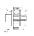
- Fig. 2 is an axial sectional view of a gearbox 100 according to a comparative example, wherein the axis of the planetary wheel stage 120 and the axes of the planetary wheels 121 a, 121 b, 121 c, respectively, are parallel to the axis of the stationary gear ring 110.
- the axis of the planetary wheel stage 120 is not tilted with regard to the axis of the stationary gear ring 110.
- the planetary wheels 121 a, 121 b, 121 c are supported by a planetary wheel carrier 122, which is in turn mechanically coupled to the shaft 123 that may support a wind rotor.
- a torque force of the wind rotor may be applied to the shaft 123 from the side 0, which designates the load input side of the gearbox 100.
- the shaft 133 of the sun gear 130 may mechanically connect to an electric machine such as a generator and the like on side 1, which designates the load output side of the gearbox 100.
- Fig. 3 is an axial sectional view of a gearbox 100 according to the comparative example of Fig. 2 , wherein the axis of the planetary wheel stage 120 and the axes of the planetary wheels 121 a, 121 b, 121 c, respectively, are tilted with regard to the axis of the stationary gear ring 110 by a tilt angle y.
- the tilt may be due to bending moments and/or torque forces applied to the shaft 123.
- a plane spanned by the axis of the planetary wheel stage 120 and the axis of the stationary gear ring 110 may include a vector of the gravity force and extend in vertical direction.
- Fig. 4 which is a view A of the stationary gear ring 110 of the gearbox 100 depicted in Fig. 3 from the load input side 0, the stationary gear ring 110 is installed in the gearbox 100, wherein a plane spanned by the tilted axis of the planetary wheel stage 120 and the axis of the stationary gear component 110 defines a 90°-position (12h-position) and a 270°-position (18h-position).
- the plane spanned by the axis of the planetary wheel stage 120 and said stationary gear component 110 may include a vector of the gravity force.
- the plane spanned by axis of the planetary wheel stage 120 and said stationary gear component 110 may not comprise the vector of the gravity force.
- the 0°-position (9h-position) is offset by 90° in clockwise direction from the plane spanned by the axis of the planetary wheel stage 120 and the axis of the stationary gear component 110 as seen from the load input side 0 of the gearbox 100 and measured from the load-side intersecting position of the stationary gear component 110 and said plane.
- the load-side intersecting position is the one that is closer to the load.
- the angle ⁇ is set to be 0°.
- the angle ⁇ is measured in clockwise direction starting from this 0° position as seen from the load input side, as defined in Fig. 4 .
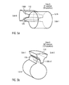
- Fig. 5a-d are partial perspective views A of the gearbox 100 depicted in Fig. 3 , which schematically illustrate the effects of the tilt of the axis of one of the planetary wheels 121 a with regard to the axis of the stationary gear ring 110 in various positions of the engagement between the planetary wheel 121 a and the stationary gear ring 110 along the tooth trace 115.
- Fig. 5a shows the planetary wheel 121 a engaged with the stationary gear ring 110 in the 0°-position (9h-position), Fig.
- FIG. 5b shows the planetary wheel 121 a engaged with the stationary gear ring 110 in the 90°-position (12h-position)
- Fig. 5c shows the planetary wheel 121 a engaged with the stationary gear ring 110 in the 180°-position (15h-position)
- Fig. 5d shows the planetary wheel 121a engaged with the stationary gear ring 110 in the 270°-position (18h-position).
- the effective inclination of the axis of the planetary wheel 121 a with regard to the axis of the stationary gear ring 110 in a generally radial plane by virtue of the influence of the tilt angle y is zero, wherein the effective skew of the axis of the planetary wheel 121 a with regard to the axis of the stationary gear ring 110 in a generally radial plane by virtue of the influence of the tilt angle y is at its maximum.
- the tooth 126 of the planetary wheel 121a and the tooth 116a of the stationary gear ring 110 contact each other only on side 1 and form a gap increasing in the direction of side 0.
- the side 1 bears the entire load and is subjected to considerable compressive stress.
- the effective inclination of the axis of the planetary wheel 121 a with regard to the axis of the stationary gear ring 110 by virtue of the influence of the tilt angle y is at its maximum, whereas the effective skew of the axis of the planetary wheel 121 a with regard to the axis of the stationary gear ring 110 by virtue of the influence of the tilt angle y is zero.
- the tooth 126 of the planetary wheel 121 a and the tooth 116a+i of the stationary gear ring 110 may contact each other along an oblique line inclining from side 1 to side 0.
- the effective inclination of the axis of the planetary wheel 121 a with regard to the axis of the stationary gear ring 110 by virtue of the influence of the tilt angle y is zero again, whereas the effective skew of the axis of the planetary wheel 121 a with regard to the axis of the stationary gear ring 110 by virtue of the influence of the tilt angle y is back at its maximum.
- the tooth 126 of the planetary wheel 121a and the tooth 116a+2i of the stationary gear ring 110 contact each other only on side 0 and form a gap increasing in the direction of side 1.
- the side 0 bears the entire load and is subjected to considerable compressive stress.
- the invention allows for individual adjustment of the tooth flank profiles of the teeth 116a, ..., 116n along the tooth trace 115, as the above-identified orientation of the stationary gear ring 110 in the state of installation and the load acting on the shaft 123 that caused the tilt can be determined in advance. Accordingly, an overall tooth flank compensation amount for each one of the teeth 116a .. 116n along the tooth trace 115 as a function of the e.g. the tilt between the axis of the planetary wheel stage 120 and the axis of the stationary gear component 110, the position angle ⁇ of each tooth along the tooth trace 115 and other factors could also be determined in advance.
- the overall tooth flank compensation amount ⁇ f_( ⁇ ) represents the deviation from a regular flank line that may be calculated for tooth flanks and tooth flank profiles, respectively, as described in section 21.4.5 b) of the handbook " Maschinenmony Band II - Getriebe all Zell, Zahnradgetriebe - Kunststoffn, Stirnradgetriebe”; Niemann, Gustav; 2nd revised edition 1983, Springer-Verlag, in consideration of DIN 3960 to 3967 as valid in November 1980 and the norms referred to therein.
- the tooth flank profiles of the teeth 116a, ..., 116n of the stationary gear ring 110 along the tooth trace 115 are individually adjusted so as to compensate for the tilt of the axis of the planetary wheel stage 120 with regard to the axis of the stationary gear ring 110 by virtue of the influence of an external load. Therefore, an optimum engagement contact between the planetary wheels 121a, 121b, 121c and the stationary gear ring 110 can be secured at every engagement position along the tooth trace 115. Hence, mechanical loads can be transferred between the planetary wheels 121 a, 121 b, 121 c and the stationary gear ring 110 more evenly, such that local peaks of compressive stress can be reduced and the operational lifetime of the gearbox 100 is significantly increased.
- Fig. 6 schematically illustrates a wind power plant 250, which may comprise an electric machine 253 that is mechanically coupled to a wind rotor 251 via a gearbox 200, which may have a configuration as discussed above with reference to the gearbox 100. That is, the gearbox 200 in some illustrative embodiments comprises a stationary ring gear 210 having provided therein an appropriate tooth trace correction that varies along the circumferential direction of the ring gear 210, as described above. Moreover, the gearbox 200 may comprise any further components, such as a planetary wheel stage of which only a carrier 222 is schematically illustrated in Fig. 6 .
- the wind rotor 251 is mechanically coupled via a shaft 252 to the carrier 222, which in turn transfers mechanical load to the stationary ring gear 210. Consequently, due to the substantially horizontal orientation of the shaft 252 a certain tilt of the shaft 252 caused by the wind rotor 251 may occur, for instance caused by the weight of the wind rotor 251 in combination with any external wind loads.
- the electric machine 253 and the gearbox 200 are accommodated in a housing or nacelle 254, which in turn is positioned on a tower 255 wherein the nacelle 254 is rotatably attached to the tower 255 by means of a yaw system, which may comprise a gear system 200b and a drive assembly 256, wherein in some illustrative embodiments the gear system 200b may comprise at least one "stationary" gear 210b, wherein it should be appreciated that the term "stationary” may refer to an arrangement in which the gear 210b is fixed relative to the nacelle 254 or the tower 255.
- the stationary component 210b of the yaw system may be provided with a varying tooth trace correction.
- the wind turbine 250 may be positioned in an environment in which a preferred wind direction is present.
- the load distribution along the tooth trace of the gear 210b may also significantly differ when averaged over elongated time intervals, while at the same time any small angle corrections may have to be performed within a specific section of the gear 210b.
- the gear 210b may be stationary with respect to the nacelle 254 so that upon orienting the nacelle 254 with respect to the wind direction also a substantially imbalanced load distribution may occur along the tooth trace of the gear 210b.
- the transferred mechanical power may be significantly less compared to the power transferred by the gearbox 200, superior performance and durability for a given size and weight of the gear system 200b may be accomplished on the basis of similar concepts by applying a tooth trace correction depending on the angular position within the gear 21 0b
- Fig. 7 schematically illustrates a process tool 360 that is appropriate for performing a position-dependent tooth trace correction and/or for fabricating teeth of a gear component 310, wherein the tooth configuration varies along the tooth trace in accordance with a specified target flank profile distribution.
- the process tool 360 represents a grinding tool configured for performing a controlled grinding process or material removal process in order to form or modify a certain pattern in the gear component 310.
- the process tool 360 comprises a drive system 362, which may enable the movement of a grinding tool 369 along several spatial axes, for instance as indicated by a height axis 363, a translational axis 364 and a rotation axis 365.
- the process tool 360 comprises any appropriate component, for instance on the basis of well-established and available conventional grinding tools, which however are not shown in Fig. 7 .
- the process tool 360 comprises a work piece holder or stage 367, which is appropriately configured to receive the gear 310 in a substantially non-processed state or a preprocessed state with respect to any teeth to be formed or modified in the gear 310.
- the work piece holder 367 may comprise an appropriate drive assembly (not shown) in order to provide a rotational movement along a rotation axis, as indicated by 366.
- the process tool 360 comprises a control unit 361, which applies appropriate control signals to the drive assembly 362 and the work piece holder 367. Consequently, during operation of the tool 367 in some illustrative embodiments a basic configuration of corresponding teeth may be generated in the gear 310 after which, in conventional strategies, a further manufacturing step is applied so as to modify the flank profiles of the previously generated teeth in accordance with a desired target flank profile.
- control data 370 are provided to the control unit 361 so as to enable a specific tooth trace correction for at least some different positions along the tooth trace of the gear 310.
- the control data 370 may comprise appropriate data for generating control signals, which in turn may cause the drive assembly 362 so as to modify the basic tooth shape in accordance with a desired target profile 371, which may be obtained on the basis of calculation and experiments, as for instance previously discussed above.
- the control data set 370 is appropriately configured to enable the individual adaptation of each tooth provided in the gear 310. For example, upon controlling and monitoring the rotational movements 365, 366, the translation 364 and the stroke in the height direction 363 may be controlled such that a desired shape for each tooth is obtained so as to comply with the target profile 371.
- the positioning of the gear 310 on the work piece holder 367 may be appropriately “modulated", for instance by influencing the position coordinates for the gear 310, at least in one direction.
- the position coordinates of at least some point of the gear 310 are shifted, for instance substantially in height, as indicated by the positioning element 368, thereby "superimposing" an additional component when moving the gear 310 relatively to the grinding tool 369 upon operating the process tool 360.
- the positioning of the gear 310 may be adjusted so as to deviate from the regular position, while at the same time appropriate control data 370 which, per se, may result in a circumferentially varying trace correction may be applied so that the combined effect may thus yield the desired target profile for each of the teeth of the gear 310.
- superior flexibility may be obtained, for instance by "extending" the degree of modulation, which may for instance be restricted by the available range of movement of the drive assembly 362, since by appropriately positioning the gear 310 an additional degree of freedom is obtained in adjusting the finally desired tooth trace correction.
- the present invention is not limited to arrangements involving a ring gear as the stationary gear component but likewise applies to arrangements involving a stationary planet carrier or a stationary sun gear or another gear of the gearbox as the stationary gear component, since the formula (I) remains valid for such alternative arrangements.
Landscapes
- Engineering & Computer Science (AREA)
- General Engineering & Computer Science (AREA)
- Mechanical Engineering (AREA)
- Life Sciences & Earth Sciences (AREA)
- Sustainable Development (AREA)
- Sustainable Energy (AREA)
- Chemical & Material Sciences (AREA)
- Combustion & Propulsion (AREA)
- Retarders (AREA)
- Gears, Cams (AREA)
Abstract
Description
- Generally, the present invention relates to gear systems, such as planetary gears, in which superior load distribution may be achieved by applying a tooth trace correction on teeth of at least some components of the gearbox. In particular, the present invention relates to gearboxes that are configured to transmit high mechanical powers, such as gearboxes of wind power plants.
- In many technical applications drive trains have to be used, which have to transfer a large mechanical power, wherein a conversion of input torque and rotation speed rate into appropriate output torque and rate is required. To this end, a wide variety of gear systems has been developed so as to comply with the various requirements in many technical fields. Generally, in a gear system at least two gears are engaged with each other so as to transfer mechanical forces in compliance with the application under consideration. The actual mechanical coupling between the various gear components takes place via the surface areas of the corresponding meshing components, such as the teeth of rotary or linear gear components. Consequently, corresponding compressive forces may act on the individual teeth flank, wherein the forces are transferred via the contact surfaces of the individual teeth meshing with each other. Therefore, the actually occurring mechanical pressure and thus the mechanical stress acting on the individual teeth significantly depends on the area or point or line of interaction, which in turn is affected by the overall profile of the teeth flanks. Generally, in high performance gearboxes the mechanical efficiency, the noise generation, the duration and the like are important aspects that have to be addressed in order to comply with the requirements of the various applications. For example, the engagement of the individual teeth of two gears can be adjusted so as to obtain an improvement in one or more of the above-mentioned aspects, for instance in view of noise reduction and the like, by appropriately adapting the flank profile of the teeth. To this end, frequently a so-called tooth trace correction is applied during the fabrication of one or more gears of a gearbox in order to appropriately adapt the tooth flanks to the expected load condition during operation of the gear system. For example, the leading flank of the teeth may be provided with a different profile compared to the trailing flank of the teeth, when substantially a predefined direction of rotation of the gears is encountered in the application under consideration. The process of tooth trace correction is thus a well-established concept for improving the load conditions for various components of the gearbox, for instance by applying appropriate additional manufacturing steps upon fabricating the individual gears of the gear system and/or by controlling the manufacturing process for the teeth, for instance the grinding process, in order to establish the teeth so as to have the desired target flank profile.
- In many applications a substantially balanced load distribution in complex gearboxes is an essential aspect when the gearbox is designed for transferring high mechanical powers. For example, over the last decades wind energy has proven to be one important component for providing alternative energy due to the superior availability of wind energy and the moderately high cost-effectiveness of modern wind power plants. Presently, most of the highly efficient wind turbines are designed on the basis of wind rotors supported by a substantially horizontal shaft that in turn is mechanically coupled to a gearbox in order to convert the moderately low rotation speed of the wind rotor into a desired high rotation speed of an electrical generator. The conversion of the low input speed and high input torque into a high output speed and moderately low output torque is frequently accomplished on the basis of a planetary gear system, which thus has to transfer a mechanical power of several hundred kW to several MW, depending on the size of the wind power plant. Upon installing a wind power plant with horizontal rotor axis these gearboxes have to be mounted in the nacelle on a tower with a height of several 10 meters to 100 meters or more so that, for economical and technical reasons, generally a high power-to-weight ratio is desirable for the gearbox. For this reason, the weight of the gearbox is typically reduced as much as possible in order to obtain a desired power-to-weight ratio, thereby necessitating the components of the gearbox to be dimensioned closely to the material fatigue limits. On the other hand, the gearboxes have to be operated in remote locations, possibly in sophisticated environmental conditions, for instance offshore, so that regular maintenance intervals may represent an important cost factor, which in turn significantly influences the overall profitability of the wind power plant. Consequently, manufacturers of planetary gear systems for wind turbines have to meet very different requirements, for instance increasing the power-to-weight ratio, which requires reducing the amounts of required materials for the various gears, and providing superior durability at a reduced number of maintenance events over the lifetime of the wind turbine. The latter aspect may, however, require superior materials or an increased amount of material for enhancing the mechanical strength of the various components and/or the application of superior manufacturing techniques, such as sophisticated tooth trace corrections in order to reduce any load variations that may occur in the individual components of the planetary gear system.
- Frequently, a gearbox structure is used in wind power plants in which a stationary ring gear of the planetary system engages with the planetary wheel whose carrier in turn is mechanically coupled to the shaft that supports the wind rotor. On the other hand, the sun gear is typically mechanically connected to an output shaft of the planetary gear system, which in turn may be coupled to a further gear system or to an electric machine. Consequently, the significant diameter of the wind rotor in combination with typically varying wind conditions, in particular in sophisticated environments, may result in a pronounced variation of the load conditions acting on the planetary gear system. That is, the torque transferred from the wind rotor via the shaft into the planetary stage of the gearbox may finally result in corresponding varying load conditions for the stationary ring gear and the sun gear. Consequently, great efforts are being made in estimating the load conditions for various operating states in order to apply sophisticated tooth trace corrections for the planetary wheels, the sun gear and the stationary ring gear. To this end, an appropriate tooth flank profile is determined for the teeth of at least one of these components in order to obtain reduced variability of the resulting load conditions. It turns out, however, that the conventional tooth trace correction concept may not efficiently address the varying load conditions, which are particularly introduced by the planetary wheel carrier connected to a mechanical load that induces strongly varying torque conditions, such as the wind rotor of a wind turbine.
- In view of the situation described above, it is an object of the present invention to provide gearboxes and manufacturing techniques in order to provide for superior balance of load conditions in a gearbox.
- According to one aspect of the present invention, the object is solved by a gearbox that comprises a stationary gear component having a plurality of teeth formed along a tooth trace. At least some of the plurality of teeth differ in their tooth flank profiles at least at an initial phase of the operational lifetime of the gearbox. The gearbox further comprises at least one rotary gear that is mechanically coupled to a subset of the teeth of the stationary gear component. It may prove advantageous when the tooth flank profiles of at least some teeth of the stationary gear component are individually adjusted. This may be accomplished by individually forming the teeth and/or by individually machining the teeth, the tooth flanks and/or the tooth flank profiles. The leading and/or trailing tooth flank profile of each tooth can be individually adjusted, preferably such that said tooth flank profile comprises geometrical variations along the axial direction of said stationary gear component.
- According to the present invention, at least some teeth of the stationary gear component are provided along the tooth trace thereof so as to provide for varying tooth geometries. A difference in flank profile of a tooth or generally a difference in tooth geometry is to be understood such that at least a first tooth is provided along the tooth trace which has a first flank profile, ie. a leading flank and/or a trailing flank profile, that differs from the corresponding flank profile of a second tooth so that the first and second teeth are configured to be operated at different load conditions that may be encountered along the different locations along the tooth trace. Consequently, the stationary gear component may be provided so as to have an appropriately adapted tooth profile depending on the location of a respective tooth along the tooth trace, which may thus allow for a superior load distribution. The variance in the tooth profile may be achieved by determining the stress conditions of the teeth depending on their position along the tooth trace and by appropriately adapting the shape or profiles of the tooth under consideration at the various locations of interest so that the adapted shape deviations and the torque induced by locally varying stress conditions may compensate each other or may at least be reduced. That is, in particular, any deviations or deflections of the teeth induced by torque forces varying along the tooth trace, such as the perimeter of ring gear and the like, or the length of a linear gear component, may be compensated for or may be at least significantly reduced for deviations caused by the rotary gear in a highly non-symmetric manner along the tooth trace.
- It may prove helpful when said tooth flank profiles are individually adjusted as a function of at least one of the following parameters:
- a. a parameter representing a position of the tooth to be adjusted along said tooth trace;
- b. a parameter representing a positional and/or directional and/or dimensional relation between said rotary gear and said stationary gear component, preferably a parameter representing a tilt between the axis of said rotary gear and the axis of said stationary gear component and/or a parameter representing a shaft skew and/or a parameter representing a shaft inclination as calculated in accordance with DIN 3964 of November 1980;
- c. a parameter relating to the transmission of energy and/or the gear engagement between said rotary gear and said stationary gear component, preferably a parameter representing a working pressure angle between said rotary gear and said stationary gear component;
- d. a parameter representing a dimension of said rotary gear and/or a dimension of said stationary gear component, preferably a parameter representing a width of the respective tooth face of the stationary gear component.
- The individual adjustment of the tooth flank profiles is preferably accomplished by individually forming and/or individually machining the teeth, tooth flanks or tooth flank profiles, respectively. In this case, mechanical loads can be transferred between the rotary gear and said stationary gear component more evenly, such that local peaks of compressive stress can be reduced and the operational lifetime of the gearbox is increased.
- It may prove beneficial when said tooth flank profiles are individually adjusted as a function of the following formula (I):

wherein - ϕ =
- angle of the position of the tooth to be adjusted along said tooth trace, wherein the angle is preferably measured in a clockwise direction in relation to the center axis of the stationary gear component as seen from the load input side of the gearbox, wherein the position representing an angle ϕ of 0° is most preferably a position which is offset by 90° in clockwise direction from a load-side intersecting position of a plane spanned by the axis of said rotary gear and by the axis of said stationary gear component when intersecting, and said stationary gear component, as seen from the load input side of the gearbox;
- f_γ =
- amount of the effective flank line angular deviation by virtue of the influence of the tilt of the the axis of said rotary gear when intersecting the axis of said stationary gear component, wherein f_γ = b* tan (y) and b corresponds to the width of the tooth along an axial direction of said stationary gear component;
- α_wt =
- working pressure angle of the gear engagement between said rotary gear and said stationary gear component; and
- Δf_(ϕ)
- = overall tooth flank compensation amount by virtue of the influence of the parameters ϕ, f_y and a_wt.
- The overall tooth flank compensation amount ϕf_(ϕ) represents the deviation from a regular flank line that may be calculated for tooth flanks and tooth flank profiles, respectively, e.g. as described in section 21.4.5 b) of the handbook "Maschinenelemente Band II - Getriebe allgemein, Zahnradgetriebe - Grundlagen, Stirnradgetriebe"; Niemann, Gustav; 2nd revised edition 1983, Springer-Verlag, in consideration of DIN 3960 to 3967 as valid in November 1980 and the norms referred to therein. With such tooth trace correction, the transfer of mechanical loads from the rotary gear to the stationary gear component can be significantly improved, such that local peaks of compressive stress can be reduced and the operational lifetime of the gearbox is still further increased.
- It may also prove useful when a subset of teeth having different tooth flank profiles is repeated along the tooth trace. This is preferred when only certain teeth of the rotary gear engage with the teeth of the stationary gear component in a predictable manner.
- In some illustrative embodiments the stationary component is a ring gear of a planetary gear system and thus a torque of specific direction may thus result in a corresponding variation of the resulting deflections of any teeth in the stationary gear ring. In this case, the tooth profile varying along the circumferential direction of the ring gear may appropriately be adapted to this variation of the resulting tooth stress conditions in order to provide for superior load distribution.
- In some illustrative embodiments the at least one rotary gear is one of a plurality of planet wheels of the planetary gear and is engaged with the ring gear. Moreover, in further illustrative embodiments the at least one rotary gear is connected to a mechanical load so as to cause compressive forces that act on the teeth flank of the stationary gear component in a locally varying manner. Consequently, for many externally applied torque forces caused by the mechanical load coupled to the at least one rotary gear the resulting compressive forces, which may typically result in a certain deviation of shape of the corresponding teeth flank, may efficiently be reduced or compensated for, as is also discussed above. To this end, the difference in flank profile of the teeth of the stationary gear component is correlated to the compressive forces induced by the mechanical load in a manner that is position-dependent along the tooth trace. For example, the tilting of the shaft of a wind rotor may efficiently be taken into consideration upon applying a tooth trace correction to the stationary ring gear, thereby efficiently reducing or compensating the resulting compressive forces, which would otherwise be unevenly distributed along the circumferential direction of the ring gear. Consequently, contrary to conventional tooth trace corrections, the variation of the tooth profiles along the circumferential direction in correlation with, for instance, the resulting tilt or other well predictable torque forces caused by the wind rotor, may thus provide for a superior load distribution thereby resulting in superior mechanical efficiency and/or durability and the like.
- In still further illustrative embodiments, the gearbox comprises at least one further rotary gear that is engaged with the at least one rotary gear and which is mechanically coupled to a generator of a wind power plant. In further illustrative embodiments, the gearbox is configured to transfer a mechanical power of 100 kW or higher so that in particular the gearbox may be implemented in sophisticated wind power plants of high power, wherein the superior load distribution in the gearbox may result in an increased power-to-weight ratio, since generally the size of the various components of the gearbox may be reduced. On the other hand, the power-to-weight ratio may be increased for a given size of the gearbox by enabling the transfer of an increased mechanical power due to the superior robustness and reliability of the ring gear teeth.
- Generally, the inventive gearbox including the position-dependent tooth trace correction of the stationary gear component may provide for superior lifetime and performance of the drive train, which in the case of sophisticated wind turbines may allow the specifying of higher load conditions for a given family of wind turbines without having to increase the overall size of the gearbox and thus of any other periphery of the wind turbine.
- In other illustrative embodiments the gearbox may be used in a drive train of a wind turbine yaw system in order to adjust the angle position of a nacelle of the wind power plant. In this case, the torque forces of the wind rotor that is properly oriented to the wind direction may result in predictable load conditions at the teeth of a "stationary" gear (i.e., yaw gear), wherein the mechanical stress may thus vary along the circumferential direction of the "stationary" gear. Also in this case, a circumferentially varying tooth trace correction is applied in some illustrative embodiments in order to provide for superior mechanical robustness and reliability of the gear system of a yaw system of the wind turbine.
- According to a further aspect of the present invention, the above object is solved by a method of fabricating a stationary gear component of a gearbox that is to be engaged with at least one rotary gear of the gearbox. The method comprises adjusting a flank profile of teeth of the stationary gear component so as to differ for at least some of the teeth along a tooth trace of the stationary gear component.
- Hence, by applying the above-specified method the stationary gear component of a gearbox, as specified above, may be fabricated wherein the adjustment of the varying tooth profile or tooth configuration along the tooth trace may be accomplished during the manufacturing process, ie. during a process for forming the teeth of the gear component and/or during a specific tooth flank correction process in which the desired final flank profile is adjusted in a separate fabrication process so as to obtain individual flank profiles for at least some different teeth of the stationary gear component.
- In one illustrative embodiment, the adjustment of a flank profile of teeth of the gear component comprises the determining of a force distribution along the tooth trace for a given flank profile for each of the teeth and the adapting of the flank profile of the at least some teeth in correlation to the determined force distribution. For example, according to this embodiment a certain force distribution may be "predicted" in order to estimate the load conditions during the actual operation of a gearbox, wherein the forces may be different along the tooth trace of the stationary gear component. Consequently, in correlation to the determined force distribution, which may typically result in a certain shape deflection, the target flank profile may be determined for at least some different positions along the tooth trace in order to obtain a superior distribution of the resulting load and thus shape deflection of the teeth.
- It should be appreciated that the determination of the force distribution at the various positions along the tooth trace for a given tooth profile may not require the actual fabrication of teeth having the same tooth profile but may involve appropriate simulation or calculation techniques, which may predict the deflection of a corresponding basic shape of the teeth for a specified force distribution. From the corresponding results the desired final flank profile at various positions along the tooth trace may then be determined, for instance by appropriate calculations, experiments and the like, in order to obtain the desired even load distribution. For example, in some illustrative embodiments, the torque forces which act on the stationary gear component via the at least one rotary gear when coupled to a substantially horizontal shaft of a wind rotor are determined. Hence, as already discussed above, in particular a superior load distribution may be accomplished in a stationary component of a gearbox in a wind power plant. Also in this case it is to be noted that the determination of any torque forces conveyed via the at least one rotary gear component onto the stationary gear component may be accomplished by experiments, calculations, measurement results of actual implemented gearboxes and the like.
- In one illustrative embodiment adjusting a flank profile of the teeth of the stationary gear component comprises establishing a relative motion between the stationary gear component and a material removal tool and performing a material removal process so as to form the at least some teeth that differ in their flank profiles. In this case, well-established mechanical manufacturing processes, such as grinding and the like, may efficiently be applied in order to form the individual teeth of the stationary component so as to have the position-dependent tooth profile. That is, a grinding tool may appropriately be "scanned" across the basic body of the stationary component in order to obtain the teeth of the gear component having the individually adjusted flank profiles. It should be appreciated that the correspondingly controlled grinding process may be applied during the actual manufacturing process, ie. during a process for producing the teeth from a non-shaped basic material block of the stationary component, thereby implementing the desired target profile for each of the teeth. In other cases, the process of fabricating the teeth and adjusting the final individual flank profile may involve a plurality of manufacturing steps, at least one of which is performed such that a varying tooth trace correction is achieved.
- In a further illustrative embodiment, adjusting a flank profile of the teeth further comprises establishing a control data set on the basis of a target profile for each of the teeth and controlling the relative motion by using the control data set. In this embodiment the process tool, such as a grinding machine, has implemented therein an appropriate control mechanism operated on the basis of the control data set in order to appropriately control the relative position between the grinding or generally material removal tool and the work piece, i.e. the stationary gear component. In this manner, the varying tooth trace correction can be implemented into existing grinding tools by establishing an appropriate control data set, which in turn may be established on the basis of a correlation between the determined force distribution and the required adapted overall configuration of the individual teeth that is appropriate for compensating or reducing the position-dependent tooth deflections caused by the determined force distribution.
- In one illustrative embodiment the adjusting of the flank profile of the teeth further comprises the positioning of the stationary gear component on a support of a material removal tool, such as a grinding tool, in order to obtain different position coordinates of the stationary gear component along at least one spatial direction for at least two different locations along the tooth trace. For example, the gear component may be positioned on a work piece stage of the process tool in a defined "non-even" manner so as to superimpose the difference in position coordinates in at least one spatial direction to the relative motion between the support stage and a grinding tool of the machine under consideration. For example, a desired offset in height between various circumferential positions is introduced upon positioning the gear component on a work piece holder, which may result in a corresponding "wobbling" that is superimposed to the relative motion, which is generally selected so as to obtain a basic substantially identical tooth profile for any of the teeth of the gear component. Thus, an additional movement is obtained by the locally varying position coordinates, for instance the varying height of the gear component when attached to the work piece holder in order to provide for the desired locally varying tooth trace correction.
- It should be appreciated that the introduction of a varying position coordinate, i.e. an intentionally introduced "uneven" support of the work piece may efficiently be combined with an appropriate control data set, which itself results in an individual adjustment of the flank profiles, thereby achieving superior flexibility and, if desired, an increased range of variability of the tooth trace corrections. For example, a certain limitation of superimposing an additional tooth trace correction movement for an individual adaptation of flank profiles based on an appropriate control of the grinding tool may be circumvented by using an "uneven" attachment of the gear component on the work piece holder of the grinding machine.
- Consequently, load distributions of stationary gear components may efficiently be determined in advance, for instance on the basis of calculations, experiments, measurements and the like, and appropriate individual flank profiles are then determined so as to reduce or compensate any variability of tooth deflections in the stationary gear component. In this manner, in particular for high power gear systems such as the gearboxes of wind power plants, increased lifetime for a given power range and size of the gearbox are achieved, while the time interval between regular maintenance events may also be prolonged without sacrificing robustness and reliability of the gearboxes.
- With reference to the accompanying drawings, further illustrative embodiments will now be described in more detail.
- In the figures
- Fig. 1 a
- schematically illustrates a sectional view of a planetary gear;
- Fig. 1 b
- schematically depicts a portion of the stationary ring gear with teeth having varying flank profiles;
- Fig. 1 c
- schematically illustrates a sectional view of the ring gear with different flank profiles at different circumferential positions;
- Fig. 2
- is an axial sectional view of a gearbox of a comparative example, wherein the axis of the planetary wheel stage is parallel to the axis of the stationary gear ring;
- Fig. 3
- is an axial sectional view of a gearbox of the comparative example, wherein the axis of the planetary wheel stage is tilted with regard to the axis of the stationary gear ring;
- Fig. 4
- is a view A of the stationary gear ring of the gearbox depicted in
Fig. 3 from the load input side, indicating the 0°-position (9h-position), the 90°-position (12h-position), the 180°-position (15h-position) and the 270°-position (18h-position), respectively, of the engagement between the planetary wheel and the stationary gear ring; - Fig. 5a-d
- are partial perspectives views A of the gearbox depicted in
Fig. 3 , which schematically illustrate the impact of the tilt of the axis of the planetary wheel stage with regard to the axis of the stationary gear ring in a 0°-position (9h-position), a 90°-position (12h-position), a 180°-position (15h-position) and a 270°-position (18h-position), respectively, of the engagement between one of the planetary wheels and the stationary gear ring; - Fig. 6
- schematically illustrates a sectional view of a wind power plant including a planetary gearbox with a stationary ring gear having a varying tooth trace correction; and
- Fig. 7
- schematically illustrates a sectional view of a grinding system for performing the circumferentially varying tooth trace correction.
-
Fig. 1a schematically illustrates a cross-sectional view of agear system 100 which may be provided in the form of a planetary system configured for transferring a mechanical power of at least 100 kW or significantly higher. Thegearbox 100 comprises astationary gear component 110, such as a ring gear, which is in engagement with a plurality of planetary wheels 121a, 121b, 121c of aplanetary wheel stage 120. Typically, theplanetary wheel stage 120 may comprise awheel carrier 122, which in turn may be attached to ashaft 123 that rotatably supports a load such as a rotor and the like. Moreover,sun gear 130 may be provided so as to be in engagement with theplanetary wheel stage 120 wherein ashaft 133 of thesun gear 130 may mechanically connect to an electric machine such as a generator and the like. It should be appreciated that the configuration of thegearbox 100 may be altered in any manner as is required for complying with the specific application under consideration. For example, two or more stages may be implemented in thegearbox 100 or theplanetary wheel stage 120 may comprise more planetary wheels than what is shown inFig. 1 a. - As discussed above, the
ring gear 110 is provided in the form of a "stationary" component of thegearbox 100, which is to be understood such that thering gear 110 is rigidly attached to ahousing 101 of thegearbox 100, which in turn may be attached to any appropriate support, as required for accommodating the mechanical loads applied to thegearbox 100. Moreover, thering gear 110 comprises atooth trace 115, which is to be understood as a baseline or generally a base surface on which appropriately shaped teeth (not shown inFig. 1 a) are arranged so as to mesh with corresponding teeth of the planetary wheels 121a, 121b, 121c of theplanetary wheel stage 120. It should be appreciated that corresponding teeth may also extend in a direction perpendicular to the drawing plane ofFig. 1 a and may have any appropriate basic configuration, for instance the corresponding teeth may be applied as helical teeth, ie. as components that may be inclined with respect to the circumferential direction of thetooth trace 115. In other cases, a substantially linear configuration of the corresponding teeth may be implemented except for a corresponding tooth trace correction along a "width" direction of thecomponent 110, which is to be understood as the direction perpendicular to the drawing plane ofFig. 1a . - Due to the stationary nature of the
ring gear 110 with respect to theplanetary wheel stage 120, generally a torque force applied to theshaft 123 of thecarrier 122 may generally result in compressive forces along thetooth trace 115 of thestationary ring gear 110 conveyed via the planetary wheels 121 a, 121b, 121c. For a substantially spatially constant torque acting on theshaft 123, however, the resulting force distribution along thetooth trace 115 may vary depending on the position of the individual planetary wheels 121 a, 121b, 121c. For example, the resulting compressive forces acting on any teeth flank that are currently engaged with the planetary wheel 121 a, may be significantly greater compared to the associated forces transferred by the planetary wheels 121b, 121 c for the given torque conditions so that generally the load distribution with respect to the given input torque along thetooth trace 115 of thestationary component 110 differs along thetooth trace 115. Consequently, the resulting deflection of teeth for a given equal flank profile will also conventionally result in a different shape deviation so that, for instance, in a section 115a of the tooth trace 115 a premature fatigue of the teeth of thering gear 110 may result. According to the principles disclosed herein, however, the flank profiles of the teeth vary along thetooth trace 115, preferably in correlation with the expected force distributions associated with one or more predictable load conditions. For example, an appropriate tooth trace correction may be applied so as to take into consideration the increased compressive forces within the section 115a compared to sections 115b, 115c in which, for deposition of theplanetary wheel stage 120 as shown inFig. 1a , a significantly reduced amount of compressive forces will occur for the same torque condition caused by an external force acting on theshaft 123. Consequently, by appropriately adapting the overall tooth trace correction, i.e. establishing different flank profiles within the section 115a on the one hand and the sections 115b, 115c on the other hand, for instance due to the difference in shape deviation, an appropriate load distribution may be obtained. It should be appreciated that a difference in the flank profile of the individual teeth (not shown) may also be established within each individual section 115a, depending on the desired positional "resolution" of the varying tooth trace correction. For example, in some illustrative embodiments, the flank profile of each tooth is individually adjusted on the basis of its position along thetooth trace 115 and for one or more desired externally induced load conditions. -
Fig. 1 b schematically illustrates a portion of thegearbox 100 in greater detail. As illustrated, a portion of thestationary gear ring 110 is shown so as to have a plurality of teeth 116a, ..., 116n positioned along thetooth trace 115, as is also discussed above. At least some of the teeth 116a, ..., 116n have a different flank profile and thus a different geometry or configuration or shape. For example, the tooth 116a has a first flank profile 117a which, as discussed above, may also vary along a width direction, ie. along a direction perpendicular to the drawing plane ofFig. 1 b. On the other hand, a second tooth 116n has a corresponding shape or flank profile 117n, which differs from the profile 117a. Similarly, at least some of the teeth 116b, 116c, ... may differ in their associated flank profile, depending on the position of the corresponding tooth along thetooth trace 115. For example, as shown inFig. 1b , some of the teeth 116a, ..., 116n such as the teeth 116b, 116c, ... are in mesh or engagement with some of the teeth 126a, ..., 126m of the planetary wheel 121 a. Hence, the profiles of the teeth 116b, 116c are correlated with the corresponding circumferential position of these teeth and may thus result in a superior load distribution for a given external load applied to thegear 110 via the planetary wheel 121 a, as discussed above. For example, the respective flank profiles are selected such that generally the stress conditions for the teeth 116b, 116c is similar compared to, for instance, the tooth 116n, when the planetary wheel 121 a moves along thetooth trace 115, however under the same external torque or load conditions. For example, in the position indicated by the dashed line of the wheel 121a for a constant flank profile of the teeth 116a, ..., 116n a significantly different load distribution would be obtained, as discussed above, which however according to the appropriately adapted flank profile may thus be more evenly distributed so that after several rotations of the wheel 121 a, and any further planetary wheels not shown inFig. 1b . each of the teeth 116a, ..., 116n of thestationary ring gear 110 has experienced a very similar mechanical stress. - Furthermore, as explained above, any intermediate teeth between the teeth 116a, ..., 116n may have an appropriately adapted flank profile so as to comply with the varying load conditions along the length of the
tooth trace 115 for the one or more specified load conditions applied via the one or more planetary wheels 121 a. - In some illustrative embodiments an appropriate tooth trace correction may also be applied to the teeth 126a, ..., 126m which may be appropriate for at least some of the individual flank profiles of the teeth 116a, ..., 116n so as to obtain a desired load distribution. That is to say, due to the reduced diameter and number of the teeth 126a, ..., 126m compared to the
ring gear 110, the teeth of the wheel 121a may have to engage with different types of flank profiles. Thus, the corresponding tooth trace correction may represent an appropriate "compromise" so as to obtain the desired degree of load distribution, which is substantially determined by the adapted flank profile of the teeth 116a, ..., 116n of thegear 110. In other words, the tooth trace correction for the wheel 121 a may depend on the varying flank profiles of the teeth of thering gear 110. In other illustrative embodiments, depending on the configuration of thegearbox 100, the tooth trace correction on the planetary wheel 121a may be provided within sections. A section length may correspond to a circumferential length of the planetary wheel 121a so that the well defined subset set of the teeth 121a, ..., 126m within that section may engage with a well defined subset of the teeth corresponding to the section of thetooth trace 115 under consideration. If the corresponding tooth trace correction along thetooth trace 115 is repeated in a "section-wise" manner, then also a varying tooth trace correction may be applied to the planetary wheel 121 a, since in each section of thetrace 115 only certain teeth will engage with each other in a predictable manner, thereby enabling a superior adaptation and load distribution. -
Fig. 1 c schematically illustrates a portion of thegearbox 100. As illustrated, a portion of thegearing 110 is illustrated on the basis of a tooth 116a having its associated flank profile 117a, which differs from the flank profile 117n of a further tooth 116n. In the example shown, the difference in the flank profiles 117a, 117n may be obtained by varying the size of a contact surface 118a, 118n of the teeth 116a, 116n, respectively. When, for instance, for a superior spatial balancing of the load conditions, i.e. of the compressive force component acting on the various teeth flank 116a, 116n requires a local reduction of the resulting mechanical pressure in the tooth 116a, the corresponding tooth trace correction may thus result in an enhanced overall contact surface when engaging with atooth 126, as indicated by the surface 118a. On the other hand, the reduced size of the contact surface 118n may thus be appropriate for inducing substantially the same overall mechanical stress in the tooth 116n for given external torque conditions, as discussed above, thereby generally enhancing overall robustness and reliability of thering gear 110. It should be appreciated that the adaptation of the corresponding contact surface areas 118a, 118n is only one of several measures in order to provide the individually adapted flank profiles or shapes 117a, 117n. For example, the opposite flanks may also receive corresponding differently shaped profiles and/or the profiling along the tooth width, i.e. along the direction perpendicular to the drawing plane ofFig. 1 c , may be individually adapted for the teeth 116a, 116n, respectively. It should be appreciated that applying a tooth flank adaptation individually for each of the teeth 116a, ..., 116n may, in some illustrative embodiments, involve the modification of different components of each individual tooth. For instance, in one or more of the teeth only one tooth flank may be appropriately profiled, while in other teeth both tooth flanks may be subjected to a dedicated flank profiling process. - It should be appreciated that a progression of forces or load conditions along the
tooth trace 115 of thestationary gear component 110 may be obtained by means of calculation, experiments and the like, in which sophisticated simulation programmes may be used for determining the mechanical stress conditions at the various angle of positions along thetooth trace 115, or wherein alternatively or in addition to simulation calculations, experimental data may be gathered in order to obtain a correlation between a specified external load condition, for instance caused by a tilt of a wind rotor, and the angular position along thetooth trace 115 of thering gear 110. - The tilt angle may be defined as the angle between the axis of the
planetary wheel stage 120 and the axis of the saidstationary gear component 110, or as the angle between one of the axes of said rotary gear 121 a, 121b, 121c when intersecting the axis of the saidstationary gear component 110. When contemplating the axes of the rotary gears 121a, 121b, 121c instead of the axis of theplanetary wheel stage 120, the tilt angle is the same, as the axes of the rotary gears 121 a, 121b, 121c and the axis of theplanetary wheel stage 120 are parallel to each other. However, the axes of the rotary gears 121 a, 121b, 121c may only intersect the axis of thestationary gear 110 twice during the revolution of around the axis of thestationary gear 110, namely when running through the 90°-position (12h-position) and the 270°-position (18h-position). For a better comprehension of the tilt of the axis of theplanetary wheel stage 120 with regard to the axis of thestationary gear ring 110, and the effects by virtue of the tilt on the engagement between the planetary wheels 121 a, 121b, 121c and thestationary gear ring 110, a comparative example will now be described with particular reference toFigs. 2-5 . -
Fig. 2 is an axial sectional view of agearbox 100 according to a comparative example, wherein the axis of theplanetary wheel stage 120 and the axes of the planetary wheels 121 a, 121 b, 121 c, respectively, are parallel to the axis of thestationary gear ring 110. In this case, the axis of theplanetary wheel stage 120 is not tilted with regard to the axis of thestationary gear ring 110. The planetary wheels 121 a, 121 b, 121 c are supported by aplanetary wheel carrier 122, which is in turn mechanically coupled to theshaft 123 that may support a wind rotor. A torque force of the wind rotor may be applied to theshaft 123 from theside 0, which designates the load input side of thegearbox 100. Theshaft 133 of thesun gear 130 may mechanically connect to an electric machine such as a generator and the like onside 1, which designates the load output side of thegearbox 100. -
Fig. 3 is an axial sectional view of agearbox 100 according to the comparative example ofFig. 2 , wherein the axis of theplanetary wheel stage 120 and the axes of the planetary wheels 121 a, 121 b, 121 c, respectively, are tilted with regard to the axis of thestationary gear ring 110 by a tilt angle y. The tilt may be due to bending moments and/or torque forces applied to theshaft 123. In this case, a plane spanned by the axis of theplanetary wheel stage 120 and the axis of thestationary gear ring 110 may include a vector of the gravity force and extend in vertical direction. The effects by virtue of the tilt on the gear engagement between one of the planetary wheels 121 a and thestationary gear ring 110 along thetooth trace 115 under such conditions will be explained in the following with reference toFigs. 4 and5a-d . - As seen in
Fig. 4 , which is a view A of thestationary gear ring 110 of thegearbox 100 depicted inFig. 3 from theload input side 0, thestationary gear ring 110 is installed in thegearbox 100, wherein a plane spanned by the tilted axis of theplanetary wheel stage 120 and the axis of thestationary gear component 110 defines a 90°-position (12h-position) and a 270°-position (18h-position). When the tilt results from the gravity force e.g. by virtue of the weight of a wind rotor, the plane spanned by the axis of theplanetary wheel stage 120 and saidstationary gear component 110 may include a vector of the gravity force. In a different case, which is not shown, when the tilt results from other external forces such as wind loads or the like, the plane spanned by axis of theplanetary wheel stage 120 and saidstationary gear component 110 may not comprise the vector of the gravity force. In any case, the 0°-position (9h-position) is offset by 90° in clockwise direction from the plane spanned by the axis of theplanetary wheel stage 120 and the axis of thestationary gear component 110 as seen from theload input side 0 of thegearbox 100 and measured from the load-side intersecting position of thestationary gear component 110 and said plane. As the plane spanned by the axis of theplanetary wheel stage 120 and thestationary gear 110 intersects and defines two positions on thestationary gear component 110, the load-side intersecting position is the one that is closer to the load. In the 0° position, the angle ϕ is set to be 0°. Hence, the angle ϕ is measured in clockwise direction starting from this 0° position as seen from the load input side, as defined inFig. 4 . -
Fig. 5a-d are partial perspective views A of thegearbox 100 depicted inFig. 3 , which schematically illustrate the effects of the tilt of the axis of one of the planetary wheels 121 a with regard to the axis of thestationary gear ring 110 in various positions of the engagement between the planetary wheel 121 a and thestationary gear ring 110 along thetooth trace 115. For ease of description, only onetooth 126 of the planetary wheel 121 a and only one tooth of thestationary gear ring 110 are shown in the state of engagement. In greater detail,Fig. 5a shows the planetary wheel 121 a engaged with thestationary gear ring 110 in the 0°-position (9h-position),Fig. 5b shows the planetary wheel 121 a engaged with thestationary gear ring 110 in the 90°-position (12h-position),Fig. 5c shows the planetary wheel 121 a engaged with thestationary gear ring 110 in the 180°-position (15h-position) andFig. 5d shows the planetary wheel 121a engaged with thestationary gear ring 110 in the 270°-position (18h-position). - As seen in
Fig. 5a , representing the 0°-position (9h-position), the effective inclination of the axis of the planetary wheel 121 a with regard to the axis of thestationary gear ring 110 in a generally radial plane by virtue of the influence of the tilt angle y is zero, wherein the effective skew of the axis of the planetary wheel 121 a with regard to the axis of thestationary gear ring 110 in a generally radial plane by virtue of the influence of the tilt angle y is at its maximum. Accordingly, thetooth 126 of the planetary wheel 121a and the tooth 116a of thestationary gear ring 110 contact each other only onside 1 and form a gap increasing in the direction ofside 0. Theside 1 bears the entire load and is subjected to considerable compressive stress. - Further, as seen in
Fig. 5b , representing the 90°-position (12h-position), the effective inclination of the axis of the planetary wheel 121 a with regard to the axis of thestationary gear ring 110 by virtue of the influence of the tilt angle y is at its maximum, whereas the effective skew of the axis of the planetary wheel 121 a with regard to the axis of thestationary gear ring 110 by virtue of the influence of the tilt angle y is zero. Accordingly, thetooth 126 of the planetary wheel 121 a and the tooth 116a+i of thestationary gear ring 110 may contact each other along an oblique line inclining fromside 1 toside 0. - Still further, as seen in
Fig. 5c , representing the 180°-position (15h-position), the effective inclination of the axis of the planetary wheel 121 a with regard to the axis of thestationary gear ring 110 by virtue of the influence of the tilt angle y is zero again, whereas the effective skew of the axis of the planetary wheel 121 a with regard to the axis of thestationary gear ring 110 by virtue of the influence of the tilt angle y is back at its maximum. Accordingly, thetooth 126 of the planetary wheel 121a and the tooth 116a+2i of thestationary gear ring 110 contact each other only onside 0 and form a gap increasing in the direction ofside 1. Here, theside 0 bears the entire load and is subjected to considerable compressive stress. - Finally, as seen in
Fig. 5d , representing the 270°-position (18h-position), the effective inclination of the axis of the planetary wheel 121 a with regard to the axis of thestationary gear ring 110 by virtue of the influence of the tilt angle y is back at its maximum, whereas the effective skew of the axis of the planetary wheel 121 a with regard to the axis of thestationary gear ring 110 by virtue of the influence of the tilt angle y is zero again. Accordingly, thetooth 126 of the planetary wheel 121a and the tooth 116a+3i of thestationary gear ring 110 may contact each other along an oblique line inclining fromside 0 toside 1. - It is apparent that the same engagement conditions apply for every one of the planetary wheels 121 a, 121b, 121c when it is in one of the above-identified engagement positions along the
tooth trace 115. - The invention allows for individual adjustment of the tooth flank profiles of the teeth 116a, ..., 116n along the
tooth trace 115, as the above-identified orientation of thestationary gear ring 110 in the state of installation and the load acting on theshaft 123 that caused the tilt can be determined in advance. Accordingly, an overall tooth flank compensation amount for each one of the teeth 116a .. 116n along thetooth trace 115 as a function of the e.g. the tilt between the axis of theplanetary wheel stage 120 and the axis of thestationary gear component 110, the position angle ϕ of each tooth along thetooth trace 115 and other factors could also be determined in advance. The overall tooth flank compensation amount for the tooth flanks and tooth flank profiles, respectively, of the teeth 116a, ..., 116n of thestationary gear ring 110 along thetooth trace 115 may be calculated in accordance with the following formula (I):
wherein - ϕ =
- angle of the position of the tooth to be adjusted along the
tooth trace 115, wherein the angle is measured in clockwise direction in relation to the center axis of thestationary gear component 110 as seen from theload input side 0 of thegearbox 100, wherein the position representing the position angle ϕ of 0° is a position which is offset by 90° in clockwise direction from a load-side intersecting position of the plane spanned by the axis of theplanetary wheel stage 120 and the axis of thestationary gear component 110, and thestationary gear component 110, as seen from theload input side 0 of thegearbox 100, as shown inFig. 4 ; - f_y =
- amount of the effective flank line angular deviation by virtue of the influence of the tilt γ the axis of the
planetary wheel stage 120 and the axis of thestationary gear component 110, wherein f_γ=b* tan (y) and b corresponds to the width of the tooth along an axial direction of saidstationary gear component 110, wherein the amount of the effective flank line angular deviation f_y may be calculated in accordance with DIN 3964 of November 1980, for example; - α_wt =
- working pressure angle of the gear engagement between one of the rotary gears 121 a, 121 b, 121 c and the
stationary gear component 110, which may be identified, for example, in accordance with formula (21.3/17) of the handbook "Maschinenelemente Band II - Getriebe allgemein, Zahnradgetriebe - Grundlagen, Stirnradgetriebe"; Niemann, Gustav; 2nd revised edition 1983, Springer-Verlag; and - Af_(ϕ) =
- overall tooth flank compensation amount by virtue of the influence of the parameters ϕ, f_y and α_wt.
- The overall tooth flank compensation amount Δf_(ϕ) represents the deviation from a regular flank line that may be calculated for tooth flanks and tooth flank profiles, respectively, as described in section 21.4.5 b) of the handbook "Maschinenelemente Band II - Getriebe allgemein, Zahnradgetriebe - Grundlagen, Stirnradgetriebe"; Niemann, Gustav; 2nd revised edition 1983, Springer-Verlag, in consideration of DIN 3960 to 3967 as valid in November 1980 and the norms referred to therein.
- According to the invention, the tooth flank profiles of the teeth 116a, ..., 116n of the
stationary gear ring 110 along thetooth trace 115 are individually adjusted so as to compensate for the tilt of the axis of theplanetary wheel stage 120 with regard to the axis of thestationary gear ring 110 by virtue of the influence of an external load. Therefore, an optimum engagement contact between the planetary wheels 121a, 121b, 121c and thestationary gear ring 110 can be secured at every engagement position along thetooth trace 115. Hence, mechanical loads can be transferred between the planetary wheels 121 a, 121 b, 121 c and thestationary gear ring 110 more evenly, such that local peaks of compressive stress can be reduced and the operational lifetime of thegearbox 100 is significantly increased. -
Fig. 6 schematically illustrates awind power plant 250, which may comprise anelectric machine 253 that is mechanically coupled to awind rotor 251 via agearbox 200, which may have a configuration as discussed above with reference to thegearbox 100. That is, thegearbox 200 in some illustrative embodiments comprises astationary ring gear 210 having provided therein an appropriate tooth trace correction that varies along the circumferential direction of thering gear 210, as described above. Moreover, thegearbox 200 may comprise any further components, such as a planetary wheel stage of which only acarrier 222 is schematically illustrated inFig. 6 . Thus, thewind rotor 251 is mechanically coupled via ashaft 252 to thecarrier 222, which in turn transfers mechanical load to thestationary ring gear 210. Consequently, due to the substantially horizontal orientation of the shaft 252 a certain tilt of theshaft 252 caused by thewind rotor 251 may occur, for instance caused by the weight of thewind rotor 251 in combination with any external wind loads. Theelectric machine 253 and thegearbox 200 are accommodated in a housing ornacelle 254, which in turn is positioned on atower 255 wherein thenacelle 254 is rotatably attached to thetower 255 by means of a yaw system, which may comprise a gear system 200b and adrive assembly 256, wherein in some illustrative embodiments the gear system 200b may comprise at least one "stationary" gear 210b, wherein it should be appreciated that the term "stationary" may refer to an arrangement in which the gear 210b is fixed relative to thenacelle 254 or thetower 255. - Consequently, by providing the
stationary ring gear 210 with the varying tooth trace correction, as discussed above, superior performance and durability of thegearbox 200 may be accomplished since a certain load condition, for instance a certain tilt angle y of theshaft 252, may be taken into consideration in designing thegearbox 200. Consequently, for at least one load condition caused by external influences, such as the tilt angle γ, an enhanced load distribution may be accomplished within thegearbox 200 thereby enabling the processing of higher mechanical input powers for a given volume and weight of thegearbox 200 compared to conventional devices. Thus, for a given family of wind turbines 250 a greater power specification may be used, or in other cases for a given power specification the overall size and thus weight of thegearbox 200 may be reduced without negatively affecting durability and performance. - In other illustrative embodiments, in addition to or alternatively to providing the
gearbox 200 with thering gear 210 having the position-dependent tooth trace correction, the stationary component 210b of the yaw system may be provided with a varying tooth trace correction. For example, thewind turbine 250 may be positioned in an environment in which a preferred wind direction is present. In this case, the load distribution along the tooth trace of the gear 210b may also significantly differ when averaged over elongated time intervals, while at the same time any small angle corrections may have to be performed within a specific section of the gear 210b. In other cases, the gear 210b may be stationary with respect to thenacelle 254 so that upon orienting thenacelle 254 with respect to the wind direction also a substantially imbalanced load distribution may occur along the tooth trace of the gear 210b. Although generally the transferred mechanical power may be significantly less compared to the power transferred by thegearbox 200, superior performance and durability for a given size and weight of the gear system 200b may be accomplished on the basis of similar concepts by applying a tooth trace correction depending on the angular position within thegear 21 0b -
Fig. 7 schematically illustrates aprocess tool 360 that is appropriate for performing a position-dependent tooth trace correction and/or for fabricating teeth of agear component 310, wherein the tooth configuration varies along the tooth trace in accordance with a specified target flank profile distribution. In some illustrative embodiments theprocess tool 360 represents a grinding tool configured for performing a controlled grinding process or material removal process in order to form or modify a certain pattern in thegear component 310. For example, theprocess tool 360 comprises adrive system 362, which may enable the movement of a grindingtool 369 along several spatial axes, for instance as indicated by aheight axis 363, atranslational axis 364 and arotation axis 365. It should be appreciated that theprocess tool 360 comprises any appropriate component, for instance on the basis of well-established and available conventional grinding tools, which however are not shown inFig. 7 . Moreover, theprocess tool 360 comprises a work piece holder orstage 367, which is appropriately configured to receive thegear 310 in a substantially non-processed state or a preprocessed state with respect to any teeth to be formed or modified in thegear 310. To this end, thework piece holder 367 may comprise an appropriate drive assembly (not shown) in order to provide a rotational movement along a rotation axis, as indicated by 366. Consequently, by appropriately initiating a relative movement between the grindingtool 369 and thegear 310, the outer circumference of thegear 310 may be formed or patterned in accordance with the basic tooth configuration of thetool 369. To this end, theprocess tool 360 comprises acontrol unit 361, which applies appropriate control signals to thedrive assembly 362 and thework piece holder 367. Consequently, during operation of thetool 367 in some illustrative embodiments a basic configuration of corresponding teeth may be generated in thegear 310 after which, in conventional strategies, a further manufacturing step is applied so as to modify the flank profiles of the previously generated teeth in accordance with a desired target flank profile. According to the principles disclosed herein,appropriate control data 370 are provided to thecontrol unit 361 so as to enable a specific tooth trace correction for at least some different positions along the tooth trace of thegear 310. To this end, thecontrol data 370 may comprise appropriate data for generating control signals, which in turn may cause thedrive assembly 362 so as to modify the basic tooth shape in accordance with a desiredtarget profile 371, which may be obtained on the basis of calculation and experiments, as for instance previously discussed above. In some illustrative embodiments, thecontrol data set 370 is appropriately configured to enable the individual adaptation of each tooth provided in thegear 310. For example, upon controlling and monitoring therotational movements 365, 366, thetranslation 364 and the stroke in theheight direction 363 may be controlled such that a desired shape for each tooth is obtained so as to comply with thetarget profile 371. - In other illustrative embodiments, additionally or alternatively to controlling the relative movement between the
gear 310 and the grindingtool 369 on the basis of thecontrol data set 370, the positioning of thegear 310 on thework piece holder 367 may be appropriately "modulated", for instance by influencing the position coordinates for thegear 310, at least in one direction. For example, by means of providing an intentionally modified surface of theholder 367, the position coordinates of at least some point of thegear 310 are shifted, for instance substantially in height, as indicated by thepositioning element 368, thereby "superimposing" an additional component when moving thegear 310 relatively to the grindingtool 369 upon operating theprocess tool 360. For example, upon rotating theholder 367, due to thepositioning element 368, a certain degree of "wobbling" is moderated on the rotational motion 366 thereby enabling corresponding modification of the resulting tooth trace correction, even if thecontrol unit 361 may provide control signals that may correspond to a conventional spatially constant trace correction. Consequently, by appropriately selecting the size and shape of theposition element 368 or by fixing thegear 310 in an appropriate modified manner on thework piece stage 367, a desired profile along the tooth trace of thegear 310 may be accomplished. - In still other illustrative embodiments, the positioning of the
gear 310 may be adjusted so as to deviate from the regular position, while at the same timeappropriate control data 370 which, per se, may result in a circumferentially varying trace correction may be applied so that the combined effect may thus yield the desired target profile for each of the teeth of thegear 310. In this manner, superior flexibility may be obtained, for instance by "extending" the degree of modulation, which may for instance be restricted by the available range of movement of thedrive assembly 362, since by appropriately positioning thegear 310 an additional degree of freedom is obtained in adjusting the finally desired tooth trace correction. - The present invention is not limited to arrangements involving a ring gear as the stationary gear component but likewise applies to arrangements involving a stationary planet carrier or a stationary sun gear or another gear of the gearbox as the stationary gear component, since the formula (I) remains valid for such alternative arrangements.
Claims (10)
- A gear box (100) comprising
a stationary gear component (110) having a plurality of teeth (116a, ..., 116n) formed along a tooth trace (115), at least some of said plurality of teeth (116a, ..., 116n) differing in their tooth flank profiles at least at an initial phase of an operational lifetime of said gear box (100), and
at least one rotary gear (121a, 121b, 121c) mechanically coupled to a subset of said teeth. - The gear box (100) of claim 1, wherein said tooth flank profiles are individually adjusted as a function of at least one of the following parameters:a. a parameter (ϕ) representing a position of the tooth to be adjusted along said tooth trace (115);b. a parameter (y) representing a positional and/or directional and/or dimensional relation between said rotary gear (121 a, 121b, 121c) and said stationary gear component (110), preferably a parameter (γ) representing a tilt between the axes of said rotary gear (121a, 121b, 121c) and said stationary gear component (110);c. a parameter (αwt) relating to the transmission of energy and/or the gear engagement between said rotary gear (121 a, 121 b, 121 c) and said stationary gear component (110), preferably a parameter (αwt) representing a working pressure angle between said rotary gear (121a, 121b, 121c) and said stationary gear component (110);d. a parameter representing a dimension of said rotary gear and/or a dimension of said stationary gear component, preferably a parameter representing a width of the respective tooth face of the stationary gear component (110).
- The gear box (100) of any one of the preceding claims, wherein said tooth flank profiles are individually adjusted as a function of the following formula:

whereinϕ = angle of the position of the tooth to be adjusted along said tooth trace (115), wherein the angle is preferably measured in clockwise direction in relation to the center axis of the stationary gear component (110) as seen from the load input side (side 0) of the gearbox (100), wherein the position representing an angle ϕ of 0° is most preferably a position which is offset by 90° in clockwise direction from a load-side intersecting position of a plane spanned by the axis of said rotary gear (121 a, 121 b, 121c) and by the axis of said stationary gear component (110) when intersecting, and said stationary gear component (110), as seen from the load input side (side 0) of the gearbox (100);f_Y = amount of the effective flank line angular deviation by virtue of the influence of the tilt (y) the axis of said rotary gear (121 a, 121 b, 121 c) when intersecting the axis of said stationary gear component (110), wherein f_y = b* tan (y) and b corresponds to the width of the tooth along an axial direction of said stationary gear component (110);α_wt = working pressure angle of the gear engagement between said rotary gear (121 a, 121b, 121c) and said stationary gear component (110); andΔf_(ϕ) = overall tooth flank compensation amount by virtue of the influence of the parameters ϕ, f_γ and α_wt. - The gear box of any one of the preceding claims, which is configured to meet at least one of the following requirements:a. Said stationary component (110) is a ring gear of a planetary gear stage.b. Said at least one rotary gear (121 a, 121 b, 121 c) is one of a plurality of planet wheels of said planetary gear stage engaged with said ring gear (110).c. Said at least one rotary gear (121 a, 121b. 121 c) is connected to a mechanical load so as to cause compressive forces to act on said teeth flank (116a, .., 116n) of said stationary gear component (110) that vary along said tooth trace (115) during movement of said at least one rotary gear (121a, 121b, 121c).d. A difference in tooth flank profiles of said at least some of said plurality of teeth (116a, ..., 116n) is correlated to said variation of said compressive forces.e. Said at least one rotary gear (121 a, 121b, 121c) is configured to be coupled to a rotor of a wind power plant.f. The gear box (100) further comprising at least one further rotary gear (130) engaged with said at least one rotary gear (121a, 121b, 121c) and mechanically coupled to a generator of said wind power plant.g. Said stationary gear component (110) is a part of a drive train for rotating a nacelle of a wind power plant.h. Said gear box (100) is configured to transfer a mechanical power of 100 kW or higher.
- A method of fabricating a stationary gear component (110) of a gear box (100) that is to be engaged with at least one rotary gear (121 a, 121 b, 121 c) of said gear box (100), said method comprising:adjusting a flank profile of teeth (116a, ..., 116n) of said stationary gear component (110) so as to differ for at least some of the teeth (116a, ..., 116n) along a tooth trace (115) of said stationary gear component (110).
- The method of claim 5, wherein adjusting a flank profile of teeth (116a, ..., 116n) of said gear component (110) comprises determining a force distribution along said tooth trace (115) for a given flank profile for each of said teeth (116a, ..., 116n) and adapting the flank profile of said at least some of said teeth (116a, ..., 116n) in correlation to said determined force distribution.
- The method of claim 6, wherein determining said force distribution comprises determining torque forces acting on said stationary gear component (110) via said at least one rotary gear (121 a, 121b, 121c) when coupled to a substantially horizontal shaft of a wind rotor.
- The method of any of claims 5 to 7, wherein adjusting a flank profile of said teeth (116a, ..., 116n) comprises establishing a relative motion between said stationary gear component (110) and a material removal tool and performing a material removal process so as to form said at least some teeth that differ in their flank profiles.
- The method of claim 8, wherein adjusting a flank profile of said teeth (116a, ..., 116n) further comprises establishing a control data set on the basis of a target flank profile of each of said teeth and controlling said relative motion by using said control data set.
- The method of claim 8 or 9, wherein adjusting a flank profile of said teeth (116a, ..., 116n) further comprises positioning said stationary gear component (110) on a support of a material removal tool so as to obtain different position coordinates of said stationary gear component (110) along at least one spatial direction for at least two different locations along said tooth trace.
Priority Applications (3)
| Application Number | Priority Date | Filing Date | Title |
|---|---|---|---|
| ES11006392.2T ES2549583T3 (en) | 2011-08-03 | 2011-08-03 | Gearbox comprising a stationary gear component formed based on variable flange profiles of gear teeth |
| EP11006392.2A EP2554841B1 (en) | 2011-08-03 | 2011-08-03 | A gearbox comprising a stationary gear component formed on the basis of variable flank profiles of gear teeth |
| US13/563,386 US8613688B2 (en) | 2011-08-03 | 2012-07-31 | Gearbox comprising a stationary gear component formed on the basis of variable flank profiles of gear teeth |
Applications Claiming Priority (1)
| Application Number | Priority Date | Filing Date | Title |
|---|---|---|---|
| EP11006392.2A EP2554841B1 (en) | 2011-08-03 | 2011-08-03 | A gearbox comprising a stationary gear component formed on the basis of variable flank profiles of gear teeth |
Publications (2)
| Publication Number | Publication Date |
|---|---|
| EP2554841A1 true EP2554841A1 (en) | 2013-02-06 |
| EP2554841B1 EP2554841B1 (en) | 2015-09-16 |
Family
ID=44545428
Family Applications (1)
| Application Number | Title | Priority Date | Filing Date |
|---|---|---|---|
| EP11006392.2A Not-in-force EP2554841B1 (en) | 2011-08-03 | 2011-08-03 | A gearbox comprising a stationary gear component formed on the basis of variable flank profiles of gear teeth |
Country Status (3)
| Country | Link |
|---|---|
| US (1) | US8613688B2 (en) |
| EP (1) | EP2554841B1 (en) |
| ES (1) | ES2549583T3 (en) |
Cited By (3)
| Publication number | Priority date | Publication date | Assignee | Title |
|---|---|---|---|---|
| CN103234006A (en) * | 2013-04-08 | 2013-08-07 | 昆明理工大学 | Differential gear train of double circular arc modified cycloid gear |
| EP3045250A1 (en) * | 2015-01-19 | 2016-07-20 | Siemens Aktiengesellschaft | Method of manufacturing an internally geared hollow wheel and method for manufacturing or repairing a planetary gear |
| CN113984466A (en) * | 2021-10-14 | 2022-01-28 | 安徽科技学院 | Batch determination method for detecting soil phenolic acid |
Families Citing this family (5)
| Publication number | Priority date | Publication date | Assignee | Title |
|---|---|---|---|---|
| US8536726B2 (en) * | 2010-09-17 | 2013-09-17 | Vestas Wind Systems A/S | Electrical machines, wind turbines, and methods for operating an electrical machine |
| PT2551550E (en) * | 2011-07-29 | 2014-07-18 | Agustawestland Spa | TRAINING OF PLANETARY GEARS AND CORRESPONDING PRODUCTION METHOD |
| JP1666420S (en) * | 2019-10-03 | 2020-08-24 | ||
| DK201970782A1 (en) * | 2019-12-17 | 2020-12-15 | Vestas Wind Sys As | Wind turbine power transmission system |
| JP2026055696A (en) * | 2024-09-18 | 2026-03-31 | ナブテスコ株式会社 | Load measurement system, damage rate estimation system, life prediction system, load measurement method, damage rate monitoring method and program |
Citations (5)
| Publication number | Priority date | Publication date | Assignee | Title |
|---|---|---|---|---|
| US2956451A (en) * | 1959-02-17 | 1960-10-18 | Bowman Spencer | Planetary gear-type speed reducer |
| EP0180846A1 (en) * | 1984-10-24 | 1986-05-14 | Hitachi, Ltd. | Planetary gear type reduction starter |
| EP1600667A1 (en) * | 2004-05-25 | 2005-11-30 | Ford Global Technologies, LLC, A subsidary of Ford Motor Company | Gear and Method to optimize the vibratory behaviour from a combustion engine using a gear |
| DE102005027050A1 (en) * | 2005-06-10 | 2006-12-14 | Gkn Sinter Metals Gmbh | Motor vehicle component with toothing |
| WO2011047448A1 (en) * | 2009-10-19 | 2011-04-28 | Hansen Transmisions International, Naamloze Vennootschap | Planetary gear unit for a gearbox of a wind turbine and planet carrier for use in such planetary gear unit |
Family Cites Families (3)
| Publication number | Priority date | Publication date | Assignee | Title |
|---|---|---|---|---|
| US3043158A (en) * | 1960-07-15 | 1962-07-10 | Allis Chalmers Mfg Co | Means for maintaining a pair of mating gears in mesh |
| US3206997A (en) * | 1960-11-16 | 1965-09-21 | Gen Motors Corp | Gearing |
| DE202004021807U1 (en) * | 2003-05-30 | 2011-03-10 | Osro Gmbh | Planetary gear as a precursor for a large wind turbine generator |
-
2011
- 2011-08-03 ES ES11006392.2T patent/ES2549583T3/en active Active
- 2011-08-03 EP EP11006392.2A patent/EP2554841B1/en not_active Not-in-force
-
2012
- 2012-07-31 US US13/563,386 patent/US8613688B2/en not_active Expired - Fee Related
Patent Citations (5)
| Publication number | Priority date | Publication date | Assignee | Title |
|---|---|---|---|---|
| US2956451A (en) * | 1959-02-17 | 1960-10-18 | Bowman Spencer | Planetary gear-type speed reducer |
| EP0180846A1 (en) * | 1984-10-24 | 1986-05-14 | Hitachi, Ltd. | Planetary gear type reduction starter |
| EP1600667A1 (en) * | 2004-05-25 | 2005-11-30 | Ford Global Technologies, LLC, A subsidary of Ford Motor Company | Gear and Method to optimize the vibratory behaviour from a combustion engine using a gear |
| DE102005027050A1 (en) * | 2005-06-10 | 2006-12-14 | Gkn Sinter Metals Gmbh | Motor vehicle component with toothing |
| WO2011047448A1 (en) * | 2009-10-19 | 2011-04-28 | Hansen Transmisions International, Naamloze Vennootschap | Planetary gear unit for a gearbox of a wind turbine and planet carrier for use in such planetary gear unit |
Non-Patent Citations (2)
| Title |
|---|
| NIEMANN, GUSTAV: "Maschinenelemente Band II - Getriebe allgemein, Zahnradgetriebe - Grundlagen, Stirnradgetriebe", 1983, SPRINGER-VERLAG |
| NIEMANN, GUSTAV: "Maschinenelemente Band II - Getriebe allgemein, Zahnradgetriebe - Grundlagen, Stirnradgetriebe", vol. II, 1983, SPRINGER-VERLAG |
Cited By (4)
| Publication number | Priority date | Publication date | Assignee | Title |
|---|---|---|---|---|
| CN103234006A (en) * | 2013-04-08 | 2013-08-07 | 昆明理工大学 | Differential gear train of double circular arc modified cycloid gear |
| EP3045250A1 (en) * | 2015-01-19 | 2016-07-20 | Siemens Aktiengesellschaft | Method of manufacturing an internally geared hollow wheel and method for manufacturing or repairing a planetary gear |
| CN113984466A (en) * | 2021-10-14 | 2022-01-28 | 安徽科技学院 | Batch determination method for detecting soil phenolic acid |
| CN113984466B (en) * | 2021-10-14 | 2024-01-12 | 安徽科技学院 | A batch determination method for soil phenolic acid detection |
Also Published As
| Publication number | Publication date |
|---|---|
| EP2554841B1 (en) | 2015-09-16 |
| ES2549583T3 (en) | 2015-10-29 |
| US20130035198A1 (en) | 2013-02-07 |
| US8613688B2 (en) | 2013-12-24 |
Similar Documents
| Publication | Publication Date | Title |
|---|---|---|
| EP2554841B1 (en) | A gearbox comprising a stationary gear component formed on the basis of variable flank profiles of gear teeth | |
| JP5826866B2 (en) | Gearbox wear monitoring at power stations | |
| US8696315B2 (en) | Hub for a wind turbine and method of mounting a wind turbine | |
| EP2253841A2 (en) | Horizontal axis wind turbine | |
| EP2730779B1 (en) | Yaw brakes for wind turbines | |
| US20120244989A1 (en) | Drive unit for a wind turbine | |
| US8091199B2 (en) | Method to repair pitch control components | |
| JP2007518938A (en) | Gear transmission unit with planet carrier | |
| US9856966B2 (en) | Drivetrain assembly for a wind turbine | |
| EP3428449B1 (en) | Drivetrain for a wind turbine and method for positioning a main bearing of said drivetrain | |
| CA3054974A1 (en) | Adjustment unit for azimuth adjustment and/or pitch adjustment of a wind turbine, and method | |
| CN203257903U (en) | Bearing arranging structure, retainer and external member thereof, speed changing box and wind turbine | |
| KR20100083712A (en) | Wave generator for wave gear device | |
| US9410531B2 (en) | Wind turbine generator | |
| CA3076440C (en) | Gear set in which interacting gears have a different circular pitch | |
| EP2821638B1 (en) | Renewable energy generator | |
| EP4571101B1 (en) | A method for tracking a gear tooth meshing angle of a gearbox of a wind turbine | |
| CN208718259U (en) | Zhongting overhangs curve globoidal glass railing mounting structure | |
| US20180274519A1 (en) | Toothing for a rotary joint and rotary joint of a wind turbine | |
| KR101531265B1 (en) | Wind turbine | |
| EP2786018B1 (en) | Power generating apparatus of renewable energy and method of attaching a hydraulic pump thereof | |
| KR20150060557A (en) | Wind power generator | |
| WO2004013516A1 (en) | Gear transmission unit with planet carrier | |
| KR101480425B1 (en) | Multi-linkage arm type Rotation Angle Transfer Device | |
| KR101478078B1 (en) | Wear-monitoring of a gearbox in a power station |
Legal Events
| Date | Code | Title | Description |
|---|---|---|---|
| PUAI | Public reference made under article 153(3) epc to a published international application that has entered the european phase |
Free format text: ORIGINAL CODE: 0009012 |
|
| AK | Designated contracting states |
Kind code of ref document: A1 Designated state(s): AL AT BE BG CH CY CZ DE DK EE ES FI FR GB GR HR HU IE IS IT LI LT LU LV MC MK MT NL NO PL PT RO RS SE SI SK SM TR |
|
| AX | Request for extension of the european patent |
Extension state: BA ME |
|
| 17P | Request for examination filed |
Effective date: 20130729 |
|
| RBV | Designated contracting states (corrected) |
Designated state(s): AL AT BE BG CH CY CZ DE DK EE ES FI FR GB GR HR HU IE IS IT LI LT LU LV MC MK MT NL NO PL PT RO RS SE SI SK SM TR |
|
| 17Q | First examination report despatched |
Effective date: 20131029 |
|
| GRAP | Despatch of communication of intention to grant a patent |
Free format text: ORIGINAL CODE: EPIDOSNIGR1 |
|
| RIC1 | Information provided on ipc code assigned before grant |
Ipc: F03D 11/02 20060101AFI20150225BHEP Ipc: F16H 1/28 20060101ALI20150225BHEP Ipc: F16H 55/08 20060101ALI20150225BHEP Ipc: B23F 19/00 20060101ALI20150225BHEP |
|
| INTG | Intention to grant announced |
Effective date: 20150320 |
|
| RAP1 | Party data changed (applicant data changed or rights of an application transferred) |
Owner name: VESTAS WIND SYSTEMS A/S |
|
| GRAS | Grant fee paid |
Free format text: ORIGINAL CODE: EPIDOSNIGR3 |
|
| GRAA | (expected) grant |
Free format text: ORIGINAL CODE: 0009210 |
|
| AK | Designated contracting states |
Kind code of ref document: B1 Designated state(s): AL AT BE BG CH CY CZ DE DK EE ES FI FR GB GR HR HU IE IS IT LI LT LU LV MC MK MT NL NO PL PT RO RS SE SI SK SM TR |
|
| REG | Reference to a national code |
Ref country code: GB Ref legal event code: FG4D |
|
| REG | Reference to a national code |
Ref country code: CH Ref legal event code: EP |
|
| REG | Reference to a national code |
Ref country code: IE Ref legal event code: FG4D |
|
| REG | Reference to a national code |
Ref country code: AT Ref legal event code: REF Ref document number: 750039 Country of ref document: AT Kind code of ref document: T Effective date: 20151015 |
|
| REG | Reference to a national code |
Ref country code: DE Ref legal event code: R096 Ref document number: 602011019729 Country of ref document: DE Ref country code: ES Ref legal event code: FG2A Ref document number: 2549583 Country of ref document: ES Kind code of ref document: T3 Effective date: 20151029 |
|
| REG | Reference to a national code |
Ref country code: NL Ref legal event code: MP Effective date: 20150916 |
|
| PG25 | Lapsed in a contracting state [announced via postgrant information from national office to epo] |
Ref country code: GR Free format text: LAPSE BECAUSE OF FAILURE TO SUBMIT A TRANSLATION OF THE DESCRIPTION OR TO PAY THE FEE WITHIN THE PRESCRIBED TIME-LIMIT Effective date: 20151217 Ref country code: LT Free format text: LAPSE BECAUSE OF FAILURE TO SUBMIT A TRANSLATION OF THE DESCRIPTION OR TO PAY THE FEE WITHIN THE PRESCRIBED TIME-LIMIT Effective date: 20150916 Ref country code: NO Free format text: LAPSE BECAUSE OF FAILURE TO SUBMIT A TRANSLATION OF THE DESCRIPTION OR TO PAY THE FEE WITHIN THE PRESCRIBED TIME-LIMIT Effective date: 20151216 Ref country code: LV Free format text: LAPSE BECAUSE OF FAILURE TO SUBMIT A TRANSLATION OF THE DESCRIPTION OR TO PAY THE FEE WITHIN THE PRESCRIBED TIME-LIMIT Effective date: 20150916 |
|
| REG | Reference to a national code |
Ref country code: LT Ref legal event code: MG4D |
|
| REG | Reference to a national code |
Ref country code: AT Ref legal event code: MK05 Ref document number: 750039 Country of ref document: AT Kind code of ref document: T Effective date: 20150916 |
|
| PG25 | Lapsed in a contracting state [announced via postgrant information from national office to epo] |
Ref country code: SE Free format text: LAPSE BECAUSE OF FAILURE TO SUBMIT A TRANSLATION OF THE DESCRIPTION OR TO PAY THE FEE WITHIN THE PRESCRIBED TIME-LIMIT Effective date: 20150916 Ref country code: RS Free format text: LAPSE BECAUSE OF FAILURE TO SUBMIT A TRANSLATION OF THE DESCRIPTION OR TO PAY THE FEE WITHIN THE PRESCRIBED TIME-LIMIT Effective date: 20150916 Ref country code: HR Free format text: LAPSE BECAUSE OF FAILURE TO SUBMIT A TRANSLATION OF THE DESCRIPTION OR TO PAY THE FEE WITHIN THE PRESCRIBED TIME-LIMIT Effective date: 20150916 |
|
| PG25 | Lapsed in a contracting state [announced via postgrant information from national office to epo] |
Ref country code: NL Free format text: LAPSE BECAUSE OF FAILURE TO SUBMIT A TRANSLATION OF THE DESCRIPTION OR TO PAY THE FEE WITHIN THE PRESCRIBED TIME-LIMIT Effective date: 20150916 |
|
| PG25 | Lapsed in a contracting state [announced via postgrant information from national office to epo] |
Ref country code: IT Free format text: LAPSE BECAUSE OF FAILURE TO SUBMIT A TRANSLATION OF THE DESCRIPTION OR TO PAY THE FEE WITHIN THE PRESCRIBED TIME-LIMIT Effective date: 20150916 Ref country code: IS Free format text: LAPSE BECAUSE OF FAILURE TO SUBMIT A TRANSLATION OF THE DESCRIPTION OR TO PAY THE FEE WITHIN THE PRESCRIBED TIME-LIMIT Effective date: 20160116 Ref country code: EE Free format text: LAPSE BECAUSE OF FAILURE TO SUBMIT A TRANSLATION OF THE DESCRIPTION OR TO PAY THE FEE WITHIN THE PRESCRIBED TIME-LIMIT Effective date: 20150916 Ref country code: SK Free format text: LAPSE BECAUSE OF FAILURE TO SUBMIT A TRANSLATION OF THE DESCRIPTION OR TO PAY THE FEE WITHIN THE PRESCRIBED TIME-LIMIT Effective date: 20150916 Ref country code: CZ Free format text: LAPSE BECAUSE OF FAILURE TO SUBMIT A TRANSLATION OF THE DESCRIPTION OR TO PAY THE FEE WITHIN THE PRESCRIBED TIME-LIMIT Effective date: 20150916 |
|
| PG25 | Lapsed in a contracting state [announced via postgrant information from national office to epo] |
Ref country code: RO Free format text: LAPSE BECAUSE OF FAILURE TO SUBMIT A TRANSLATION OF THE DESCRIPTION OR TO PAY THE FEE WITHIN THE PRESCRIBED TIME-LIMIT Effective date: 20150916 Ref country code: PL Free format text: LAPSE BECAUSE OF FAILURE TO SUBMIT A TRANSLATION OF THE DESCRIPTION OR TO PAY THE FEE WITHIN THE PRESCRIBED TIME-LIMIT Effective date: 20150916 Ref country code: PT Free format text: LAPSE BECAUSE OF FAILURE TO SUBMIT A TRANSLATION OF THE DESCRIPTION OR TO PAY THE FEE WITHIN THE PRESCRIBED TIME-LIMIT Effective date: 20160118 Ref country code: AT Free format text: LAPSE BECAUSE OF FAILURE TO SUBMIT A TRANSLATION OF THE DESCRIPTION OR TO PAY THE FEE WITHIN THE PRESCRIBED TIME-LIMIT Effective date: 20150916 |
|
| REG | Reference to a national code |
Ref country code: DE Ref legal event code: R097 Ref document number: 602011019729 Country of ref document: DE |
|
| PLBE | No opposition filed within time limit |
Free format text: ORIGINAL CODE: 0009261 |
|
| STAA | Information on the status of an ep patent application or granted ep patent |
Free format text: STATUS: NO OPPOSITION FILED WITHIN TIME LIMIT |
|
| 26N | No opposition filed |
Effective date: 20160617 |
|
| PG25 | Lapsed in a contracting state [announced via postgrant information from national office to epo] |
Ref country code: DK Free format text: LAPSE BECAUSE OF FAILURE TO SUBMIT A TRANSLATION OF THE DESCRIPTION OR TO PAY THE FEE WITHIN THE PRESCRIBED TIME-LIMIT Effective date: 20150916 |
|
| REG | Reference to a national code |
Ref country code: FR Ref legal event code: PLFP Year of fee payment: 6 |
|
| PG25 | Lapsed in a contracting state [announced via postgrant information from national office to epo] |
Ref country code: SI Free format text: LAPSE BECAUSE OF FAILURE TO SUBMIT A TRANSLATION OF THE DESCRIPTION OR TO PAY THE FEE WITHIN THE PRESCRIBED TIME-LIMIT Effective date: 20150916 |
|
| PG25 | Lapsed in a contracting state [announced via postgrant information from national office to epo] |
Ref country code: MC Free format text: LAPSE BECAUSE OF FAILURE TO SUBMIT A TRANSLATION OF THE DESCRIPTION OR TO PAY THE FEE WITHIN THE PRESCRIBED TIME-LIMIT Effective date: 20150916 |
|
| REG | Reference to a national code |
Ref country code: CH Ref legal event code: PL |
|
| PG25 | Lapsed in a contracting state [announced via postgrant information from national office to epo] |
Ref country code: LI Free format text: LAPSE BECAUSE OF NON-PAYMENT OF DUE FEES Effective date: 20160831 Ref country code: CH Free format text: LAPSE BECAUSE OF NON-PAYMENT OF DUE FEES Effective date: 20160831 |
|
| REG | Reference to a national code |
Ref country code: IE Ref legal event code: MM4A |
|
| PG25 | Lapsed in a contracting state [announced via postgrant information from national office to epo] |
Ref country code: IE Free format text: LAPSE BECAUSE OF NON-PAYMENT OF DUE FEES Effective date: 20160803 |
|
| REG | Reference to a national code |
Ref country code: FR Ref legal event code: PLFP Year of fee payment: 7 |
|
| PG25 | Lapsed in a contracting state [announced via postgrant information from national office to epo] |
Ref country code: LU Free format text: LAPSE BECAUSE OF NON-PAYMENT OF DUE FEES Effective date: 20160803 |
|
| PG25 | Lapsed in a contracting state [announced via postgrant information from national office to epo] |
Ref country code: SM Free format text: LAPSE BECAUSE OF FAILURE TO SUBMIT A TRANSLATION OF THE DESCRIPTION OR TO PAY THE FEE WITHIN THE PRESCRIBED TIME-LIMIT Effective date: 20150916 Ref country code: HU Free format text: LAPSE BECAUSE OF FAILURE TO SUBMIT A TRANSLATION OF THE DESCRIPTION OR TO PAY THE FEE WITHIN THE PRESCRIBED TIME-LIMIT; INVALID AB INITIO Effective date: 20110803 Ref country code: CY Free format text: LAPSE BECAUSE OF FAILURE TO SUBMIT A TRANSLATION OF THE DESCRIPTION OR TO PAY THE FEE WITHIN THE PRESCRIBED TIME-LIMIT Effective date: 20150916 |
|
| PG25 | Lapsed in a contracting state [announced via postgrant information from national office to epo] |
Ref country code: MT Free format text: LAPSE BECAUSE OF NON-PAYMENT OF DUE FEES Effective date: 20160831 Ref country code: MK Free format text: LAPSE BECAUSE OF FAILURE TO SUBMIT A TRANSLATION OF THE DESCRIPTION OR TO PAY THE FEE WITHIN THE PRESCRIBED TIME-LIMIT Effective date: 20150916 Ref country code: TR Free format text: LAPSE BECAUSE OF FAILURE TO SUBMIT A TRANSLATION OF THE DESCRIPTION OR TO PAY THE FEE WITHIN THE PRESCRIBED TIME-LIMIT Effective date: 20150916 |
|
| PG25 | Lapsed in a contracting state [announced via postgrant information from national office to epo] |
Ref country code: BG Free format text: LAPSE BECAUSE OF FAILURE TO SUBMIT A TRANSLATION OF THE DESCRIPTION OR TO PAY THE FEE WITHIN THE PRESCRIBED TIME-LIMIT Effective date: 20150916 |
|
| REG | Reference to a national code |
Ref country code: FR Ref legal event code: PLFP Year of fee payment: 8 |
|
| PG25 | Lapsed in a contracting state [announced via postgrant information from national office to epo] |
Ref country code: AL Free format text: LAPSE BECAUSE OF FAILURE TO SUBMIT A TRANSLATION OF THE DESCRIPTION OR TO PAY THE FEE WITHIN THE PRESCRIBED TIME-LIMIT Effective date: 20150916 |
|
| PGFP | Annual fee paid to national office [announced via postgrant information from national office to epo] |
Ref country code: NL Payment date: 20180926 Year of fee payment: 9 |
|
| REG | Reference to a national code |
Ref country code: FI Ref legal event code: MAE |
|
| PG25 | Lapsed in a contracting state [announced via postgrant information from national office to epo] |
Ref country code: FI Free format text: LAPSE BECAUSE OF NON-PAYMENT OF DUE FEES Effective date: 20190803 |
|
| PGFP | Annual fee paid to national office [announced via postgrant information from national office to epo] |
Ref country code: GB Payment date: 20230822 Year of fee payment: 13 Ref country code: ES Payment date: 20230914 Year of fee payment: 13 |
|
| PGFP | Annual fee paid to national office [announced via postgrant information from national office to epo] |
Ref country code: FR Payment date: 20230824 Year of fee payment: 13 Ref country code: DE Payment date: 20230828 Year of fee payment: 13 Ref country code: BE Payment date: 20230825 Year of fee payment: 13 |
|
| REG | Reference to a national code |
Ref country code: DE Ref legal event code: R119 Ref document number: 602011019729 Country of ref document: DE |
|
| GBPC | Gb: european patent ceased through non-payment of renewal fee |
Effective date: 20240803 |
|
| REG | Reference to a national code |
Ref country code: BE Ref legal event code: MM Effective date: 20240831 |
|
| PG25 | Lapsed in a contracting state [announced via postgrant information from national office to epo] |
Ref country code: DE Free format text: LAPSE BECAUSE OF NON-PAYMENT OF DUE FEES Effective date: 20250301 |
|
| PG25 | Lapsed in a contracting state [announced via postgrant information from national office to epo] |
Ref country code: GB Free format text: LAPSE BECAUSE OF NON-PAYMENT OF DUE FEES Effective date: 20240803 |
|
| PG25 | Lapsed in a contracting state [announced via postgrant information from national office to epo] |
Ref country code: BE Free format text: LAPSE BECAUSE OF NON-PAYMENT OF DUE FEES Effective date: 20240831 |
|
| PG25 | Lapsed in a contracting state [announced via postgrant information from national office to epo] |
Ref country code: FR Free format text: LAPSE BECAUSE OF NON-PAYMENT OF DUE FEES Effective date: 20240831 |
|
| REG | Reference to a national code |
Ref country code: ES Ref legal event code: FD2A Effective date: 20250926 |
|
| PG25 | Lapsed in a contracting state [announced via postgrant information from national office to epo] |
Ref country code: ES Free format text: LAPSE BECAUSE OF NON-PAYMENT OF DUE FEES Effective date: 20240804 |