EP2554810A1 - Exhaust gas treatment device for diesel engine - Google Patents
Exhaust gas treatment device for diesel engine Download PDFInfo
- Publication number
- EP2554810A1 EP2554810A1 EP11765340A EP11765340A EP2554810A1 EP 2554810 A1 EP2554810 A1 EP 2554810A1 EP 11765340 A EP11765340 A EP 11765340A EP 11765340 A EP11765340 A EP 11765340A EP 2554810 A1 EP2554810 A1 EP 2554810A1
- Authority
- EP
- European Patent Office
- Prior art keywords
- combustible gas
- air
- ring
- chamber
- liquid fuel
- Prior art date
- Legal status (The legal status is an assumption and is not a legal conclusion. Google has not performed a legal analysis and makes no representation as to the accuracy of the status listed.)
- Granted
Links
Images







Classifications
-
- F—MECHANICAL ENGINEERING; LIGHTING; HEATING; WEAPONS; BLASTING
- F02—COMBUSTION ENGINES; HOT-GAS OR COMBUSTION-PRODUCT ENGINE PLANTS
- F02M—SUPPLYING COMBUSTION ENGINES IN GENERAL WITH COMBUSTIBLE MIXTURES OR CONSTITUENTS THEREOF
- F02M27/00—Apparatus for treating combustion-air, fuel, or fuel-air mixture, by catalysts, electric means, magnetism, rays, sound waves, or the like
- F02M27/02—Apparatus for treating combustion-air, fuel, or fuel-air mixture, by catalysts, electric means, magnetism, rays, sound waves, or the like by catalysts
-
- F—MECHANICAL ENGINEERING; LIGHTING; HEATING; WEAPONS; BLASTING
- F01—MACHINES OR ENGINES IN GENERAL; ENGINE PLANTS IN GENERAL; STEAM ENGINES
- F01N—GAS-FLOW SILENCERS OR EXHAUST APPARATUS FOR MACHINES OR ENGINES IN GENERAL; GAS-FLOW SILENCERS OR EXHAUST APPARATUS FOR INTERNAL-COMBUSTION ENGINES
- F01N13/00—Exhaust or silencing apparatus characterised by constructional features
- F01N13/009—Exhaust or silencing apparatus characterised by constructional features having two or more separate purifying devices arranged in series
- F01N13/0097—Exhaust or silencing apparatus characterised by constructional features having two or more separate purifying devices arranged in series the purifying devices are arranged in a single housing
-
- F—MECHANICAL ENGINEERING; LIGHTING; HEATING; WEAPONS; BLASTING
- F01—MACHINES OR ENGINES IN GENERAL; ENGINE PLANTS IN GENERAL; STEAM ENGINES
- F01N—GAS-FLOW SILENCERS OR EXHAUST APPARATUS FOR MACHINES OR ENGINES IN GENERAL; GAS-FLOW SILENCERS OR EXHAUST APPARATUS FOR INTERNAL-COMBUSTION ENGINES
- F01N3/00—Exhaust or silencing apparatus having means for purifying, rendering innocuous, or otherwise treating exhaust
- F01N3/02—Exhaust or silencing apparatus having means for purifying, rendering innocuous, or otherwise treating exhaust for cooling, or for removing solid constituents of, exhaust
-
- F—MECHANICAL ENGINEERING; LIGHTING; HEATING; WEAPONS; BLASTING
- F01—MACHINES OR ENGINES IN GENERAL; ENGINE PLANTS IN GENERAL; STEAM ENGINES
- F01N—GAS-FLOW SILENCERS OR EXHAUST APPARATUS FOR MACHINES OR ENGINES IN GENERAL; GAS-FLOW SILENCERS OR EXHAUST APPARATUS FOR INTERNAL-COMBUSTION ENGINES
- F01N3/00—Exhaust or silencing apparatus having means for purifying, rendering innocuous, or otherwise treating exhaust
- F01N3/02—Exhaust or silencing apparatus having means for purifying, rendering innocuous, or otherwise treating exhaust for cooling, or for removing solid constituents of, exhaust
- F01N3/021—Exhaust or silencing apparatus having means for purifying, rendering innocuous, or otherwise treating exhaust for cooling, or for removing solid constituents of, exhaust by means of filters
- F01N3/023—Exhaust or silencing apparatus having means for purifying, rendering innocuous, or otherwise treating exhaust for cooling, or for removing solid constituents of, exhaust by means of filters using means for regenerating the filters, e.g. by burning trapped particles
-
- F—MECHANICAL ENGINEERING; LIGHTING; HEATING; WEAPONS; BLASTING
- F01—MACHINES OR ENGINES IN GENERAL; ENGINE PLANTS IN GENERAL; STEAM ENGINES
- F01N—GAS-FLOW SILENCERS OR EXHAUST APPARATUS FOR MACHINES OR ENGINES IN GENERAL; GAS-FLOW SILENCERS OR EXHAUST APPARATUS FOR INTERNAL-COMBUSTION ENGINES
- F01N3/00—Exhaust or silencing apparatus having means for purifying, rendering innocuous, or otherwise treating exhaust
- F01N3/02—Exhaust or silencing apparatus having means for purifying, rendering innocuous, or otherwise treating exhaust for cooling, or for removing solid constituents of, exhaust
- F01N3/021—Exhaust or silencing apparatus having means for purifying, rendering innocuous, or otherwise treating exhaust for cooling, or for removing solid constituents of, exhaust by means of filters
- F01N3/023—Exhaust or silencing apparatus having means for purifying, rendering innocuous, or otherwise treating exhaust for cooling, or for removing solid constituents of, exhaust by means of filters using means for regenerating the filters, e.g. by burning trapped particles
- F01N3/025—Exhaust or silencing apparatus having means for purifying, rendering innocuous, or otherwise treating exhaust for cooling, or for removing solid constituents of, exhaust by means of filters using means for regenerating the filters, e.g. by burning trapped particles using fuel burner or by adding fuel to exhaust
-
- F—MECHANICAL ENGINEERING; LIGHTING; HEATING; WEAPONS; BLASTING
- F01—MACHINES OR ENGINES IN GENERAL; ENGINE PLANTS IN GENERAL; STEAM ENGINES
- F01N—GAS-FLOW SILENCERS OR EXHAUST APPARATUS FOR MACHINES OR ENGINES IN GENERAL; GAS-FLOW SILENCERS OR EXHAUST APPARATUS FOR INTERNAL-COMBUSTION ENGINES
- F01N3/00—Exhaust or silencing apparatus having means for purifying, rendering innocuous, or otherwise treating exhaust
- F01N3/02—Exhaust or silencing apparatus having means for purifying, rendering innocuous, or otherwise treating exhaust for cooling, or for removing solid constituents of, exhaust
- F01N3/021—Exhaust or silencing apparatus having means for purifying, rendering innocuous, or otherwise treating exhaust for cooling, or for removing solid constituents of, exhaust by means of filters
- F01N3/033—Exhaust or silencing apparatus having means for purifying, rendering innocuous, or otherwise treating exhaust for cooling, or for removing solid constituents of, exhaust by means of filters in combination with other devices
- F01N3/035—Exhaust or silencing apparatus having means for purifying, rendering innocuous, or otherwise treating exhaust for cooling, or for removing solid constituents of, exhaust by means of filters in combination with other devices with catalytic reactors
-
- F—MECHANICAL ENGINEERING; LIGHTING; HEATING; WEAPONS; BLASTING
- F01—MACHINES OR ENGINES IN GENERAL; ENGINE PLANTS IN GENERAL; STEAM ENGINES
- F01N—GAS-FLOW SILENCERS OR EXHAUST APPARATUS FOR MACHINES OR ENGINES IN GENERAL; GAS-FLOW SILENCERS OR EXHAUST APPARATUS FOR INTERNAL-COMBUSTION ENGINES
- F01N3/00—Exhaust or silencing apparatus having means for purifying, rendering innocuous, or otherwise treating exhaust
- F01N3/08—Exhaust or silencing apparatus having means for purifying, rendering innocuous, or otherwise treating exhaust for rendering innocuous
- F01N3/10—Exhaust or silencing apparatus having means for purifying, rendering innocuous, or otherwise treating exhaust for rendering innocuous by thermal or catalytic conversion of noxious components of exhaust
- F01N3/105—General auxiliary catalysts, e.g. upstream or downstream of the main catalyst
-
- F—MECHANICAL ENGINEERING; LIGHTING; HEATING; WEAPONS; BLASTING
- F01—MACHINES OR ENGINES IN GENERAL; ENGINE PLANTS IN GENERAL; STEAM ENGINES
- F01N—GAS-FLOW SILENCERS OR EXHAUST APPARATUS FOR MACHINES OR ENGINES IN GENERAL; GAS-FLOW SILENCERS OR EXHAUST APPARATUS FOR INTERNAL-COMBUSTION ENGINES
- F01N3/00—Exhaust or silencing apparatus having means for purifying, rendering innocuous, or otherwise treating exhaust
- F01N3/08—Exhaust or silencing apparatus having means for purifying, rendering innocuous, or otherwise treating exhaust for rendering innocuous
- F01N3/10—Exhaust or silencing apparatus having means for purifying, rendering innocuous, or otherwise treating exhaust for rendering innocuous by thermal or catalytic conversion of noxious components of exhaust
- F01N3/24—Exhaust or silencing apparatus having means for purifying, rendering innocuous, or otherwise treating exhaust for rendering innocuous by thermal or catalytic conversion of noxious components of exhaust characterised by constructional aspects of converting apparatus
- F01N3/30—Arrangements for supply of additional air
-
- F—MECHANICAL ENGINEERING; LIGHTING; HEATING; WEAPONS; BLASTING
- F01—MACHINES OR ENGINES IN GENERAL; ENGINE PLANTS IN GENERAL; STEAM ENGINES
- F01N—GAS-FLOW SILENCERS OR EXHAUST APPARATUS FOR MACHINES OR ENGINES IN GENERAL; GAS-FLOW SILENCERS OR EXHAUST APPARATUS FOR INTERNAL-COMBUSTION ENGINES
- F01N3/00—Exhaust or silencing apparatus having means for purifying, rendering innocuous, or otherwise treating exhaust
- F01N3/08—Exhaust or silencing apparatus having means for purifying, rendering innocuous, or otherwise treating exhaust for rendering innocuous
- F01N3/10—Exhaust or silencing apparatus having means for purifying, rendering innocuous, or otherwise treating exhaust for rendering innocuous by thermal or catalytic conversion of noxious components of exhaust
- F01N3/24—Exhaust or silencing apparatus having means for purifying, rendering innocuous, or otherwise treating exhaust for rendering innocuous by thermal or catalytic conversion of noxious components of exhaust characterised by constructional aspects of converting apparatus
- F01N3/36—Arrangements for supply of additional fuel
-
- F—MECHANICAL ENGINEERING; LIGHTING; HEATING; WEAPONS; BLASTING
- F01—MACHINES OR ENGINES IN GENERAL; ENGINE PLANTS IN GENERAL; STEAM ENGINES
- F01N—GAS-FLOW SILENCERS OR EXHAUST APPARATUS FOR MACHINES OR ENGINES IN GENERAL; GAS-FLOW SILENCERS OR EXHAUST APPARATUS FOR INTERNAL-COMBUSTION ENGINES
- F01N9/00—Electrical control of exhaust gas treating apparatus
- F01N9/002—Electrical control of exhaust gas treating apparatus of filter regeneration
-
- F—MECHANICAL ENGINEERING; LIGHTING; HEATING; WEAPONS; BLASTING
- F02—COMBUSTION ENGINES; HOT-GAS OR COMBUSTION-PRODUCT ENGINE PLANTS
- F02B—INTERNAL-COMBUSTION PISTON ENGINES; COMBUSTION ENGINES IN GENERAL
- F02B3/00—Engines characterised by air compression and subsequent fuel addition
- F02B3/06—Engines characterised by air compression and subsequent fuel addition with compression ignition
-
- F—MECHANICAL ENGINEERING; LIGHTING; HEATING; WEAPONS; BLASTING
- F23—COMBUSTION APPARATUS; COMBUSTION PROCESSES
- F23G—CREMATION FURNACES; CONSUMING WASTE PRODUCTS BY COMBUSTION
- F23G7/00—Incinerators or other apparatus for consuming industrial waste, e.g. chemicals
- F23G7/06—Incinerators or other apparatus for consuming industrial waste, e.g. chemicals of waste gases or noxious gases, e.g. exhaust gases
- F23G7/061—Incinerators or other apparatus for consuming industrial waste, e.g. chemicals of waste gases or noxious gases, e.g. exhaust gases with supplementary heating
- F23G7/065—Incinerators or other apparatus for consuming industrial waste, e.g. chemicals of waste gases or noxious gases, e.g. exhaust gases with supplementary heating using gaseous or liquid fuel
-
- B—PERFORMING OPERATIONS; TRANSPORTING
- B01—PHYSICAL OR CHEMICAL PROCESSES OR APPARATUS IN GENERAL
- B01D—SEPARATION
- B01D53/00—Separation of gases or vapours; Recovering vapours of volatile solvents from gases; Chemical or biological purification of waste gases, e.g. engine exhaust gases, smoke, fumes, flue gases, aerosols
- B01D53/34—Chemical or biological purification of waste gases
- B01D53/92—Chemical or biological purification of waste gases of engine exhaust gases
- B01D53/94—Chemical or biological purification of waste gases of engine exhaust gases by catalytic processes
- B01D53/944—Simultaneously removing carbon monoxide, hydrocarbons or carbon making use of oxidation catalysts
-
- F—MECHANICAL ENGINEERING; LIGHTING; HEATING; WEAPONS; BLASTING
- F01—MACHINES OR ENGINES IN GENERAL; ENGINE PLANTS IN GENERAL; STEAM ENGINES
- F01N—GAS-FLOW SILENCERS OR EXHAUST APPARATUS FOR MACHINES OR ENGINES IN GENERAL; GAS-FLOW SILENCERS OR EXHAUST APPARATUS FOR INTERNAL-COMBUSTION ENGINES
- F01N2240/00—Combination or association of two or more different exhaust treating devices, or of at least one such device with an auxiliary device, not covered by indexing codes F01N2230/00 or F01N2250/00, one of the devices being
- F01N2240/14—Combination or association of two or more different exhaust treating devices, or of at least one such device with an auxiliary device, not covered by indexing codes F01N2230/00 or F01N2250/00, one of the devices being a fuel burner
-
- F—MECHANICAL ENGINEERING; LIGHTING; HEATING; WEAPONS; BLASTING
- F01—MACHINES OR ENGINES IN GENERAL; ENGINE PLANTS IN GENERAL; STEAM ENGINES
- F01N—GAS-FLOW SILENCERS OR EXHAUST APPARATUS FOR MACHINES OR ENGINES IN GENERAL; GAS-FLOW SILENCERS OR EXHAUST APPARATUS FOR INTERNAL-COMBUSTION ENGINES
- F01N2610/00—Adding substances to exhaust gases
- F01N2610/08—Adding substances to exhaust gases with prior mixing of the substances with a gas, e.g. air
-
- F—MECHANICAL ENGINEERING; LIGHTING; HEATING; WEAPONS; BLASTING
- F01—MACHINES OR ENGINES IN GENERAL; ENGINE PLANTS IN GENERAL; STEAM ENGINES
- F01N—GAS-FLOW SILENCERS OR EXHAUST APPARATUS FOR MACHINES OR ENGINES IN GENERAL; GAS-FLOW SILENCERS OR EXHAUST APPARATUS FOR INTERNAL-COMBUSTION ENGINES
- F01N2610/00—Adding substances to exhaust gases
- F01N2610/10—Adding substances to exhaust gases the substance being heated, e.g. by heating tank or supply line of the added substance
-
- Y—GENERAL TAGGING OF NEW TECHNOLOGICAL DEVELOPMENTS; GENERAL TAGGING OF CROSS-SECTIONAL TECHNOLOGIES SPANNING OVER SEVERAL SECTIONS OF THE IPC; TECHNICAL SUBJECTS COVERED BY FORMER USPC CROSS-REFERENCE ART COLLECTIONS [XRACs] AND DIGESTS
- Y02—TECHNOLOGIES OR APPLICATIONS FOR MITIGATION OR ADAPTATION AGAINST CLIMATE CHANGE
- Y02E—REDUCTION OF GREENHOUSE GAS [GHG] EMISSIONS, RELATED TO ENERGY GENERATION, TRANSMISSION OR DISTRIBUTION
- Y02E20/00—Combustion technologies with mitigation potential
- Y02E20/12—Heat utilisation in combustion or incineration of waste
-
- Y—GENERAL TAGGING OF NEW TECHNOLOGICAL DEVELOPMENTS; GENERAL TAGGING OF CROSS-SECTIONAL TECHNOLOGIES SPANNING OVER SEVERAL SECTIONS OF THE IPC; TECHNICAL SUBJECTS COVERED BY FORMER USPC CROSS-REFERENCE ART COLLECTIONS [XRACs] AND DIGESTS
- Y02—TECHNOLOGIES OR APPLICATIONS FOR MITIGATION OR ADAPTATION AGAINST CLIMATE CHANGE
- Y02T—CLIMATE CHANGE MITIGATION TECHNOLOGIES RELATED TO TRANSPORTATION
- Y02T10/00—Road transport of goods or passengers
- Y02T10/10—Internal combustion engine [ICE] based vehicles
- Y02T10/12—Improving ICE efficiencies
-
- Y—GENERAL TAGGING OF NEW TECHNOLOGICAL DEVELOPMENTS; GENERAL TAGGING OF CROSS-SECTIONAL TECHNOLOGIES SPANNING OVER SEVERAL SECTIONS OF THE IPC; TECHNICAL SUBJECTS COVERED BY FORMER USPC CROSS-REFERENCE ART COLLECTIONS [XRACs] AND DIGESTS
- Y02—TECHNOLOGIES OR APPLICATIONS FOR MITIGATION OR ADAPTATION AGAINST CLIMATE CHANGE
- Y02T—CLIMATE CHANGE MITIGATION TECHNOLOGIES RELATED TO TRANSPORTATION
- Y02T10/00—Road transport of goods or passengers
- Y02T10/10—Internal combustion engine [ICE] based vehicles
- Y02T10/40—Engine management systems
Definitions
- the present invention relates to an exhaust gas treatment device for a diesel engine and, more particularly, to an exhaust gas treatment device for a diesel engine, which can smoothly start the generation of a combustible gas and also reduce the size of a combustible gas generator.
- a DPF is an abbreviation of a diesel particulate filter
- a PM is an abbreviation of a particulate matter included in an exhaust gas
- a DOC means a diesel oxidization catalyst.
- This type of a device is advantageous in that the PM accumulated in the DPF can be burnt and removed by raising the temperature of the exhaust gas by using the combustible gas even when the temperature of the exhaust gas is low.
- the conventional technology is problematic in that a thermal conduction plate and the central wall of an air-fuel mixing chamber are interposed between the heat-dissipating outer peripheral surface of a heater and the air-fuel mixing chamber and thus heat is indirectly radiated from the heat-dissipating outer peripheral surface of the heater to the air-fuel mixing chamber sequentially through the thermal conduction plate and the central wall of the air-fuel mixing chamber when the generation of the combustible gas is started.
- An object of the present invention is to provide an exhaust gas treatment device for a diesel engine, which can smoothly start the generation of a combustible gas and also reduce the size of a combustible gas generator.
- the characteristic of an invention according to claim 1 is as follows. As illustrated in FIG. 1 , in the exhaust gas treatment device of a diesel engine in which a combustible gas 4 is generated by a combustible gas generator 1, the combustible gas 4 is discharged from a combustible gas discharge port 6 to an exhaust passage 7 in the upper stream of a DPF 5, the combustible gas 4 is burnt by oxygen within an exhaust gas 8, a temperature of the exhaust gas 8 is raised by the heat of the combustion, and a PM accumulated in the DPF 5 is burnt and removed by the heat of the exhaust gas 8, as illustrated in FIG.
- a combustible gas generation catalyst chamber 11 is installed in the combustible gas generator 1, a combustible gas generation catalyst 13 is accommodated in the combustible gas generation catalyst chamber 11, a ring-shaped wall 14 is disposed in the starting end portion of the combustible gas generation catalyst chamber 11, an air-fuel mixing chamber 12 is formed on the inside of the ring-shaped wall 14, and air 3 and liquid fuel 2 are supplied to the air-fuel mixing chamber 12 so that an air-fuel mixture gas 23 is formed in the air-fuel mixing chamber 12, the air-fuel mixture gas 23 is supplied to the combustible gas generation catalyst 13, and the combustible gas 4 is generated using the combustible gas generation catalyst 13, and as illustrated in FIGS.
- a core member 15 is inwardly inserted into the center portion of the ring-shaped wall 14 so that the air-fuel mixing chamber 12 is formed between the inner peripheral surface 16 of the ring-shaped wall 14 and the outer peripheral surface 18 of the core member 15, and the air-fuel mixture gas 23 of the air-fuel mixing chamber 12 is supplied from the dead end of the air-fuel mixing chamber 12 to a portion near the center portion of the combustible gas generation catalyst 13, and the heat-dissipating outer peripheral surface 26 of a heater 25 is exposed to the air-fuel mixing chamber 12 by using the heater 25 as the core member 15, and when the combustible gas 4 starts being generated, heat is directly radiated from the heat-dissipating outer peripheral surface 26 of the heater 25 to the air-fuel mixing chamber 12, as illustrated in FIGS.
- an air-fuel mixture gas inlet face 27 is formed on the inner circumferential face of the combustible gas generation catalyst 13 of a ring shape, a liquid fuel retention material 28 is made along the air-fuel mixture gas inlet face 27, and the core member 15 is inserted into the central portion of the liquid fuel retention material 28 so that the air-fuel mixture gas 23 of the air-fuel mixing chamber 12 is introduced from the dead end of the air-fuel mixing chamber 12 to the air-fuel mixture gas inlet face 27 near the center of the combustible gas generation catalyst 13 through the liquid fuel retention material 28, and the heat-dissipation outer peripheral surface 26 of the heater 25 used as the core member 15 is exposed toward the liquid fuel retention material 28, so that when the combustible gas 4 starts being generated, heat is radiated from the heat-dissipation outer peripheral surface 26 of the heater 25 to the liquid fuel retention material 28.
- the invention according to claim 1 exhibits the following effects.
- the heat-dissipating outer peripheral surface 26 of the heater 25 is exposed to the air-fuel mixing chamber 12 by using the heater 25 as the core member 15 and, when the combustible gas 4 starts being generated, the heat is directly radiated from the heat-dissipating outer peripheral surface 26 of the heater 25 to the air-fuel mixing chamber 12. Accordingly, the generation of the combustible gas 4 can be smoothly started because the heat of the heater 25 is rapidly transferred to the air-fuel mixing chamber 12 and the air-fuel mixture gas 23 is rapidly formed.
- the size of the combustible gas generator 1 can be reduced because an intervening substance does not exist between the heater 25 and the air-fuel mixing chamber 12, as illustrated in FIGS. 3(A) and 3(B) , FIGS. 4(A) and 4(B) , and FIG. 7 .
- the size of the combustible gas generator 1 can be reduced because an intervening substance does not need to be installed between the heater 25 and the liquid fuel retention material 28, as illustrated in FIGS. 3(A) and 3(B) , FIGS. 4(A) and 4(B) , and FIG. 7 .
- the air-fuel mixture gas 23 of the air-fuel mixing chamber 12 is introduced into the combustible gas generation catalyst 13 through the liquid fuel retention material 28. Accordingly, thermal damage to the combustible gas generation catalyst 13 or the ring-shaped wall 14 can be prevented because the occurrence of flaming combustion of the air-fuel mixture gas 23 is suppressed by the quenching function of the liquid fuel retention material 28.
- the air-fuel mixture gas 23 of the air-fuel mixing chamber 12 is introduced from the dead end of the air-fuel mixing chamber 12 to the air-fuel mixture gas inlet face 27 near the center portion of the combustible gas generation catalyst 13 through the liquid fuel retention material 28, thereby making heat difficult to escape and maintaining a high temperature state. Accordingly, the combustible gas 4 can be efficiently generated at the air-fuel mixture gas inlet face 27 near the center portion of the combustible gas generation catalyst 13 where high catalyst activity is obtained.
- the invention according to claim 2 exhibits the following effect in addition to the effect of the invention according to claim 1.
- the DPF regeneration controller 111 initiates the supply of the air 3 and the liquid fuel 2 on the basis of a lapse of a specific pre-heating time from the start of the generation of heat of the heater 25 not on the basis of a combustible gas generation catalyst temperature. Accordingly, the time unnecessarily taken until the supply of the air 3 and the liquid fuel 2 is initiated after the generation of heat of the heater 25 is initiated does not exist, and the generation of a combustible gas 4 can be smoothly initiated.
- a thermistor and the like which is inserted into the combustible gas generation catalyst 13 is used as a combustible gas generation catalyst temperature sensor 106, but a combustible gas generation catalyst temperature sensor 106 cannot be brought in contact with the combustible gas generation catalyst 13 from a viewpoint of prevention of damage.
- a combustible gas generation catalyst temperature sensor 106 cannot be brought in contact with the combustible gas generation catalyst 13 from a viewpoint of prevention of damage.
- the start of the supply of the liquid fuel 2 after the generation of heat of the heater 25 is started is performed not on the basis of a combustible gas generation catalyst temperature, but on the basis of a lapse of a specific pre-heating time after the generation of heat of the heater 25 is started and a necessary pre-heating time is previously calculated experimentally, the generation of a combustible gas 4 can be smoothly started because it is not necessary to unnecessarily wait for a long pre-heating time until the supply of the liquid fuel 2 is initiated after the generation of heat of the heater 25 is started.
- the invention according to claim 3 exhibits the following effects in addition to the effects of the invention according to claim 1 or 2.
- an air-fuel mixture gas supply throttle part 17 is installed in the dead end of the inner peripheral surface 16 of the ring-shaped wall 14, and an air-fuel mixture gas supply throttle gap 20 is formed between the air-fuel mixture gas supply throttle part 17 and the outer peripheral surface 18 of the core member 15. Accordingly, thermal damage to the combustible gas generation catalyst 13 or the ring-shaped wall 14 can be prevented because the occurrence of flaming combustion of the air-fuel mixture gas 23 is suppressed by the quenching function of the air-fuel mixture gas supply throttle gap 20.
- the inner peripheral surface 16 of the ring-shaped wall 14 and the outer peripheral surface 18 of the core member 15 are mutually positioned and the air-fuel mixture gas supply throttle part 17 and the outer peripheral surface 18 of the core member 15 are also mutually positioned, through a spacer protrusion 29. Accordingly, the assembly of the combustible gas generator 1 can be easily performed because this positioning can be accurately performed without using a tool.
- the invention according to claim 4 exhibits the following effects in addition to the effects of the invention according to claim 3.
- a liquid fuel retention material 28 made along the air-fuel mixture gas inlet face 27 of the combustible gas generation catalyst 13 and the outer peripheral surface 18 of the core member 15 are mutually positioned through the circumferential wall 10 of the combustible gas generation catalyst chamber 11, the ring-shaped wall 14, and the spacer protrusion 29. Accordingly, the assembly of the combustible gas generator 1 can be easily performed because this positioning can be accurately performed without using a tool.
- the invention according to claim 5 exhibits the following effect in addition to the effects of the invention according to any one of claims 1 to 4.
- a position adjustment protrusion unit 30 placed more inward than the subject placement face 32 is installed in the dead end of the ring-shaped wall 14, and the position adjustment protrusion unit 30 is inwardly inserted into the starting end portion of the circumferential wall 10 of the combustible gas generation catalyst chamber 11.
- the leakage of gas between a placement face 31 and the subject placement face 32 of the ring-shaped wall 14 can be suppressed because the leakage of the air-fuel mixture gas 23 or the combustible gas 4 from the starting end portion of the combustible gas generation catalyst chamber 11 is suppressed by the tight fit of the position adjustment protrusion unit 30.
- an adiabatic space 34 is formed in the position adjustment protrusion unit 30 between the combustible gas generation catalyst 13 and a mounting bolt 33. Accordingly, the transfer of heat generated by using the combustible gas generation catalyst 13 is hindered in the adiabatic space 34, and the thermal expansion of the mounting bolt 33 is suppressed. Consequently, a reduction in the axial force of the mounting bolt 33 can be suppressed.
- the adiabatic space 34 is concavely formed in the outer peripheral surface of the position adjustment protrusion unit 30, a sealant 35 is placed in the adiabatic space 34, and the sealant 35 is sealed between the position adjustment protrusion unit 30 and the circumferential wall 10 of the combustible gas generation catalyst chamber 11.
- a plurality of liquid fuel inlets 42 and liquid fuel outlets 36 are formed at specific intervals in the gasket 40 in a peripheral direction thereof, the liquid fuel outlets 36 are drawn from the respective liquid fuel inlets 42 toward the inside of the gasket 40, a liquid fuel guidance groove 41 is concavely formed in any one of the cover placement face 38 of the ring-shaped wall 14 and the subject placement face 39 of the cover 37 in a peripheral direction thereof, the respective liquid fuel inlets 42 are made to communicate with the opening of the liquid fuel guidance groove 41, and the liquid fuel 2 supplied to the liquid fuel guidance groove 41 is flowed out from the liquid fuel outlets 36 to the air-fuel mixing chamber 12 through the respective liquid fuel inlets 42. Accordingly, the ring-shaped wall 14 can be easily processed as compared with the case in which a liquid fuel guidance passage or a liquid fuel outlet is formed in the ring-shaped wall
- the plurality of air inlets 42b and the air outlets 36b are installed at specific intervals in the gasket 40 in a peripheral direction thereof, the air outlets 36b are drawn from the respective air inlets 42b toward the inside of the gasket 40, an air guidance groove 41b is concavely formed in any one of the cover placement face 38 of the ring-shaped wall 14 and the subject placement face 39 of the cover 37 in a peripheral direction thereof, the respective air inlets 42b are made to communicate with the opening of the air guidance groove 41b, and the air 3 supplied to the air guidance groove 41b is flowed out from the air outlets 36b to the air-fuel mixing chamber 12 through the respective air inlets 42b. Accordingly, the ring-shaped wall 14 can be easily processed as compared with the case in which an air guidance passage or an air outlet is formed in the ring-shaped wall 14.
- the invention according to claim 10 exhibits the following effects in addition to the effects of the invention according to any one of claims 1 to 9.
- the plurality of liquid fuel outlets 36 is formed at specific intervals along the upper circumferential portion of the inner peripheral surface 16 of the ring-shaped wall 14 in a peripheral direction thereof, and the liquid fuel 2 flowed out from the respective liquid fuel outlets 36 is made to flow by self-weight along the inner peripheral surface 16 of the ring-shaped wall 14. Accordingly, a plurality of flows of the liquid fuel 2 flowing along the inner peripheral surface 16 of the ring-shaped wall 14 come in contact with air 3, thus becoming the air-fuel mixture gas 23. Accordingly, a concentration distribution of the air-fuel mixture gas 23 becomes uniform and thus the generation of the combustible gas 4 can be accelerated.
- the inner peripheral surface 16 of the ring-shaped wall 14 has a taper form in which the diameter of the inner peripheral surface 16 is reduced toward a lower dead end. Accordingly, the air-fuel mixture gas 23 can be formed without a hindrance because the liquid fuel 2 flows along the inner peripheral surface 16 of the ring-shaped wall 14 by self-weight even when the combustible gas generator 1 is inclined.
- the invention according to claim 11 exhibits the following effect in addition to the effects of the invention according to any one of claims 1 to 10.
- the secondary air mixing gas 49 passes through the combustible catalyst 46, part of the combustible gas 4 is subject to catalyst combustion by means of the secondary air 48, the temperature of the remainder of the combustible gas 4 passing through the combustion catalyst 46 is raised by heat of the combustion, and the combustible gas 4 having a raised temperature is discharged from the combustible gas discharge port 6 to the exhaust passage 7. Accordingly, the combustible gas 4 can be burnt by oxygen within the exhaust gas 8 because the combustible gas 4 is ignited even when a temperature of the exhaust gas 8 is low.
- the invention according to claim 12 has the following effects in addition to the effects of the invention according to claim 11.
- compartment plate placement faces 50 and 51 are formed in the dead end of the combustible gas generation catalyst chamber 11
- a compartment plate 52 is placed in and fixed to the compartment plate placement faces 50 and 51
- the secondary air mixing chamber 44 is comparted and formed on the lower side of the combustible gas generation catalyst chamber 11 by the compartment plate 52. Accordingly, the secondary air mixing chamber 44 can be simply formed.
- a plurality of combustible gas outlet holes 54 maintained at specific intervals in the circumferential portion 53 of the compartment plate 52 in a peripheral direction thereof are opened, and the combustible gas 4 generated by using the combustible gas generation catalyst 13 is supplied to the secondary air mixing chamber 44 through the combustible gas outlet holes 54.
- the air-fuel mixture gas 23 introduced into the center portion of the combustible gas generation catalyst 13 through the air-fuel mixture gas supply throttle gap 20 passes evenly through the combustible gas generation catalyst 13 toward a plurality of combustible gas outlet holes 54 in the circumferential portion 53 of the compartment plate 52 in the dead end of the combustible gas generation catalyst chamber 11, thereby being capable of efficiently generating the combustible gas 4.
- the invention according to claim 13 exhibits the following effects in addition to the effects of the invention according to claim 11.
- the compartment plate placement faces 50 and 51 are formed in the dead end of the combustible gas generation catalyst chamber 11, the compartment plate 52 is placed in and fixed to the compartment plate placement faces 50 and 51, and the secondary air mixing chamber 44 is comparted and formed on the lower side of the combustible gas generation catalyst chamber 11 by the compartment plate 52. Accordingly, the secondary air mixing chamber 44 can be simply formed.
- a combustible gas outlet gap 56 is formed along the circumferential portion 53 of the compartment plate 52 between the circumferential portion 53 of the compartment plate 52 and the chamber wall 55 of the secondary air mixing chamber 44, and the combustible gas 4 generated by using the combustible gas generation catalyst 13 is supplied to the secondary air mixing chamber 44 through the combustible gas outlet gap 56.
- the air-fuel mixture gas 23 introduced into the center portion of the combustible gas generation catalyst 13 through the air-fuel mixture gas supply throttle gap 20 passes evenly through the combustible gas generation catalyst 13 toward the combustible gas outlet gap 56 along the circumferential portion 53 of the compartment plate 52 in the dead end of the combustible gas generation catalyst chamber 11, thereby being capable of efficiently generating the combustible gas 4.
- the invention according to claim 14 exhibits the following effects in addition to the effects of the invention according to claim 12 or 13.
- a ring-shaped compartment wall 57 is installed at the center portion of the secondary air mixing chamber 44, a secondary air confluence chamber 58 on the circumference of the ring-shaped compartment wall 57 and secondary air mixing gas expansion chambers 59 and 59 on the inside of the ring-shaped compartment wall 57 are comparted by the ring-shaped compartment wall 57, the openings of the secondary air mixing gas expansion chambers 59 and 59 are closed by a compartment plate 52, a throttle hole 60 is opened at the inlet of the secondary air mixing gas expansion chamber 59, and a secondary air mixing gas outlet 61 is opened at the outlet of the secondary air mixing gas expansion chamber 59. Accordingly, the secondary air confluence chamber 58 and the secondary air mixing gas expansion chamber 59 can be formed simply and easily.
- the combustible gas 4 and the secondary air 48 are supplied from the combustible gas generation catalyst chamber 11 and the secondary air supply source 47 to the secondary air confluence chamber 58. Accordingly, the secondary air mixing gas 49 formed by joining the combustible gas 4 and the secondary air 48 in the secondary air confluence chamber 58 is formed, the secondary air mixing gas 49 is throttled by the throttle holes 60 and then diffused while being expanded in the secondary air mixing gas expansion chamber 59, and the secondary air mixing gas 49 is supplied to the combustion catalyst 46 via the secondary air mixing gas outlet 61. Consequently, catalyst combustion in the combustion catalyst 46 can be efficiently performed because a concentration distribution of the secondary air mixing gas 49 supplied to the combustion catalyst 46 becomes uniform.
- FIGS. 1 to 15 are diagrams illustrating an exhaust gas treatment device for a diesel engine according to an embodiment of the present invention.
- an exhaust gas treatment device for a vertical (upright type) multi-cylinder diesel engine is described.
- An outline of the exhaust gas treatment device is as follows. As shown in FIGS. 11 to 13 , an exhaust manifold 113 is mounted on the lateral side of the cylinder head 112, a super charger 75 is mounted over the exhaust manifold 113, and a DPF casing 67 is coupled to the exhaust turbine 76 of the super charger 75 through an exhaust pipe 66. A combustible gas generator 1 is installed in the exhaust pipe 66.
- a combustible gas 4 is generated by the combustible gas generator 1, the combustible gas 4 is discharged from a combustible gas discharge port 6 to an exhaust passage 7 in the upper stream of a DPF 5, the combustible gas 4 is burnt by oxygen within the exhaust gas 8, a temperature of the exhaust gas 8 is raised by heat of the combustion, and a PM accumulated in the DPF 5 is burnt and removed by the heat of the exhaust gas 8.
- a DOC 100 is accommodated on the upper stream of the DPF casing 67 and the DPF 5 is accommodated on the lower stream of the DPF casing 67.
- the DOC is an abbreviation of a diesel oxidation catalyst.
- the DPF 5 is a honeycomb carrier of ceramics and is a wall flow monolith in which the end parts of adjacent cells 5a are alternately blocked.
- the PM of an exhaust gas, passing through the inside of the cells 5a and the walls 5b of the cells 5a, is captured by the walls 5b of the cells 5a.
- the DOC 100 is a honeycomb carrier of ceramics.
- the DOC 100 has a flow-through structure in which an oxidation catalyst is supported and both ends of the cells 100a are opened.
- the exhaust gas 8 passes through the inside of the cells 100a.
- a combustible gas generation catalyst chamber 11 is installed in the combustible gas generator 1
- a combustible gas generation catalyst 13 is accommodated in the combustible gas generation catalyst chamber 11
- a ring-shaped wall 14 is disposed in the starting end portion (top end portion) of the combustible gas generation catalyst chamber 11
- an air-fuel mixing chamber 12 is formed on the inside of the ring-shaped wall 14, and air 3 and liquid fuel 2 are supplied to the air-fuel mixing chamber 12.
- an air-fuel mixture gas 23 is formed in the air-fuel mixing chamber 12, the air-fuel mixture gas 23 is supplied to the combustible gas generation catalyst 13, and the combustible gas 4 is generated by using the combustible gas generation catalyst 13.
- the liquid fuel 2 is diesel oil (i.e., diesel fuel) and supplied from a liquid fuel supply source 22.
- the air 3 is supplied from an air supply source 21.
- the liquid fuel supply source 22 is a fuel tank, and the air supply source 21 is an air cleaner.
- the combustible gas generation catalyst 13 supports an oxidation catalyst component in a carrier of ceramics.
- the liquid fuel 2 is evaporated by heat generated by oxidizing part of the liquid fuel by oxidizing the liquid fuel 2, whereby the combustible gas 4 is generated.
- a carrier made of a metal line having a cubic crosshatch structure or a carrier supporting a partial oxidation catalyst component may be used as the combustible gas generation catalyst 13.
- a core member 15 is inwardly inserted into the center portion of the ring-shaped wall 14 so that the air-fuel mixing chamber 12 is formed between the inner peripheral surface 16 of the ring-shaped wall 14 and the outer peripheral surface 18 of the core member 15, and the air-fuel mixture gas 23 of the air-fuel mixing chamber 12 is supplied from the dead end (bottom end portion) of the air-fuel mixing chamber 12 to a portion near the center portion of the combustible gas generation catalyst 13. Accordingly, the combustible gas 4 can be efficiently generated in the portion near the center portion of the combustible gas generation catalyst 13 where high catalyst activity is obtained because it is difficult for heat to escape and a high temperature state is maintained.
- the heat-dissipating outer peripheral surface 26 of a heater 25 is exposed to the air-fuel mixing chamber 12 by using the heater 25 as the core member 15, and when the combustible gas 4 starts being generated, heat is directly radiated from the heat-dissipating outer peripheral surface 26 of the heater 25 to the air-fuel mixing chamber 12. Accordingly, the generation of the combustible gas 4 can be smoothly started because the heat of the heater 25 is rapidly transferred to the air-fuel mixing chamber 12 and the air-fuel mixture gas 23 is rapidly formed. Furthermore, the size of the combustible gas generator 1 can be reduced because an intervening substance does not exist between the heater 25 and the air-fuel mixing chamber 12.
- the heater 25 is an electric heater for performing heating when the combustible gas 4 starts being generated. A sheathed heater in which an electric heat wire is accommodated in a metal pipe is used as the heater 25.
- an air-fuel mixture gas inlet face 27 is installed in the inner circumference of the ring-shaped combustible gas generation catalyst 13, a liquid fuel retention material 28 is made along the air-fuel mixture gas inlet face 27, the core member 15 is inserted into the center portion of the liquid fuel retention material 28, so that the air-fuel mixture gas 23 of the air-fuel mixing chamber 12 is introduced from the dead end of the air-fuel mixing chamber 12 to the air-fuel mixture gas inlet face 27 near the center portion of the combustible gas generation catalyst 13 through the liquid fuel retention material 28.
- the combustible gas 4 can be efficiently generated at the air-fuel mixture gas inlet face 27 in a portion near the center portion of the combustible gas generation catalyst 13 where high catalyst activity is obtained because it is difficult for heat to escape and a high temperature state is maintained. Furthermore, thermal damage to the combustible gas generation catalyst 13 or the ring-shaped wall 14 can be prevented because the occurrence of flaming combustion of the air-fuel mixture gas 23 is suppressed by the quenching function of the liquid fuel retention material 28.
- the liquid fuel retention material 28 is formed of a glass wool and configured to have a greater void ratio than that of the combustible gas generation catalyst 13 and to more easily maintain the liquid fuel 2 than the combustible gas generation catalyst 13.
- the liquid fuel retention material 28 may be made of metal line materials having a mesh of a cubic net or porous ceramics.
- the liquid fuel retention material 28 is illustrated as being formed on the entire air-fuel mixture gas inlet face 27, but may be along a part of the air-fuel mixture gas inlet face 27.
- the heat-dissipating outer peripheral surface 26 of the heater 25 used as the core member 15 is exposed to the liquid fuel retention material 28 so that, when the combustible gas 4 starts being generated, heat is directly radiated from the heat-dissipating outer peripheral surface 26 of the heater 25 to the liquid fuel retention material 28. Accordingly, the generation of the combustible gas 4 can be smoothly started because the heat of the heater 25 is concentratively transferred to the liquid fuel 2 retained in the liquid fuel retention material 28. Furthermore, the size of the combustible gas generator 1 can be reduced without an intervening substance between the heater 25 and the liquid fuel retention material 28.
- an air-fuel mixture gas supply throttle part 17 is installed in the dead end (bottom end portion) of the inner peripheral surface 16 of the ring-shaped wall 14 and the air-fuel mixture gas supply throttle gap 20 is formed between the air-fuel mixture gas supply throttle part 17 and the outer peripheral surface 18 of the core member 15. Accordingly, thermal damage to the combustible gas generation catalyst 13 or the ring-shaped wall 14 can be prevented because the occurrence of flaming combustion of the air-fuel mixture gas 23 is suppressed by the quenching function of the air-fuel mixture gas supply throttle gap 20.
- a spacer protrusion 29 is formed in the inner peripheral surface 16 of the ring-shaped wall 14 and the spacer protrusion 29 is brought into contact with the outer peripheral surface 18 of the core member 15. Accordingly, the inner peripheral surface 16 of the ring-shaped wall 14 and the outer peripheral surface 18 of the core member 15 are mutually positioned and the air-fuel mixture gas supply throttle part 17 and the outer peripheral surface 18 of the core member 15 are also mutually positioned, through the spacer protrusion 29. Accordingly, the assembly of the combustible gas generator 1 can be easily performed because this positioning can be accurately performed without a tool.
- the ring-shaped wall 14 and the spacer protrusion 29 are molded into one metal product.
- the spacer protrusion 29 may be formed in the outer peripheral surface 18 of the core member 15, and the spacer protrusion 29 may be brought into contact with the inner peripheral surface 16 of the ring-shaped wall 14.
- the combustible gas generation catalyst 13 of a ring shape is inwardly inserted into the combustible gas generation catalyst chamber 11, a position adjustment protrusion unit 30 is installed in the dead end of the ring-shaped wall 14, and the position adjustment protrusion unit 30 is inwardly inserted into the starting end portion (top end portion) of the circumferential wall 10 of the combustible gas generation catalyst chamber 11.
- the air-fuel mixture gas introduction gap 28 made along the air-fuel mixture gas inlet face 27 of the combustible gas generation catalyst 13 and the outer peripheral surface 18 of the core member 15 are mutually positioned through the circumferential wall 10 of the combustible gas generation catalyst chamber 11, the ring-shaped wall 14, and the spacer protrusion 29. Accordingly, the assembly of the combustible gas generator 1 can be easily performed because this positioning can be accurately performed without a tool.
- the leakage of gas between the placement face 31 and the subject placement face of the ring-shaped wall 14 can be suppressed because the leakage of the air-fuel mixture gas 23 or the combustible gas 4 from the starting end portion (top end portion) of the combustible gas generation catalyst chamber 11 is suppressed by the tight fitting of the position adjustment protrusion unit 30.
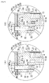
- the subject placement face 32 of the ring-shaped wall 14 is placed in the placement face 31 of the combustible gas generation catalyst chamber 11 with a gasket 19 interposed therebetween, and a cover 37 is placed in the placement face 38 of the ring-shaped wall 14 with a gasket 40 interposed therebetween. They are fastened by a mounting bolt 33.
- FIG. 3(B) is a first modification example of the assembly structure of the combustible gas generator.
- An adiabatic cushion material 9 is interposed between the surrounding face of the combustible gas generation catalyst 13 and the circumferential wall 10 of the combustible gas generation catalyst chamber 11, between the starting end face of the catalyst 13 and the position adjustment protrusion unit 30, and between the terminal end face of the catalyst 13 and a compartment plate 52 to be described later in order to fix and make adiabatic the combustible gas generation catalyst 13 in the combustible gas generation catalyst chamber 11.
- a mat of glass wool is used as the adiabatic cushion material 9.
- FIG. 4(A) is a second modification example.
- an adiabatic space 34 is formed in the position adjustment protrusion unit 30 between the combustible gas generation catalyst 13 and the mounting bolt 33. Accordingly, the transfer of heat generated by using the combustible gas generation catalyst 13 is suppressed by the adiabatic space 34 and thus the thermal expansion of the mounting bolt 33 can be suppressed. Accordingly, a reduction in the axial force of the mounting bolt 33, arising therefrom, can be suppressed.
- FIG. 4(B) is a third modification example and a second modification example of FIG. 4(A) .
- the gasket 19 between the placement face 31 of the combustible gas generation catalyst chamber 11 and the subject placement face 32 of the ring-shaped wall 14 is made unnecessary. Accordingly, a reduction in the axial force of the mounting bolt 33 resulting from a reduction in the elastic force of the gasket 19 can be suppressed.
- FIG. 3(B) and FIGS. 4(A) and 4(B) are the same as those of the embodiment shown in FIG. 3(A) .
- the same elements are assigned the same reference numerals.
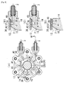
- the structure for supplying the liquid fuel and the air to the air-fuel mixing chamber is as follows. As shown in FIGS. 5(A) and 5(B) , the cover 37 is placed in the starting end portion (top end portion) of the ring-shaped wall 14, the ring-shaped cover placement face 38 is installed in the starting end portion (top end portion) of the ring-shaped wall 14, the subject placement face 39 is placed in the dead end (bottom end portion) of the cover 37, and the subject placement face 39 of the cover 37 is placed in and fixed to the cover placement face 38 of the ring-shaped wall 14 with the ring-shaped gasket 40 interposed therebetween.
- the gasket 40 includes a set of two sheets including a lower gasket 40a and an upper gasket 40b which are overlaid.
- a plurality of liquid fuel inlets 42 and liquid fuel outlets 36 are formed at specific intervals in the lower gasket 40a in a peripheral direction thereof, the liquid fuel outlets 36 are drawn from the respective liquid fuel inlets 42 toward the inside of the gasket 40, a liquid fuel guidance groove 41 is concavely formed in the cover placement face 38 of the ring-shaped wall 14 in a peripheral direction thereof, the respective liquid fuel inlets 42 are made to communicate with the opening of the liquid fuel guidance groove 41, and the liquid fuel 2 supplied to the liquid fuel guidance groove 41 is flowed out from the liquid fuel outlets 36 to the air-fuel mixing chamber 12 through the respective liquid fuel inlets 42.
- the ring-shaped wall 14 can be easily processed as compared with the case in which a liquid fuel guidance passage or a liquid fuel outlet is formed within the ring-shaped wall 14.
- the liquid fuel inlets 42, the liquid fuel outlets 36, and air inlets 42a to be described later are formed in the lower gasket 40a made of metal in a punching form.
- the liquid fuel guidance groove 41 may be installed in the subject placement face 39 of the cover 37.
- a plurality of air inlets 42b and air outlets 36b are installed at specific intervals in the upper gasket 40b in a peripheral direction thereof, the air outlets 36b are drawn from the respective air inlets 42b toward the inside of the gasket 40, an air guidance groove 41b is concavely formed in the cover placement face 38 of the ring-shaped wall 14 in a peripheral direction thereof, the respective air inlets 42b are made to communicate with the opening of the air guidance groove 41b, and the air 3 supplied to the air guidance groove 41b is flowed out from the air outlets 36b to the air-fuel mixing chamber 12 through the respective air inlets 42b.
- the respective air inlets 42b are made to communicate with the opening of the air guidance groove 41b through the air inlets 42a of the lower gasket 40a. Accordingly, the ring-shaped wall 14 can be easily processed as compared with the case in which an air guidance passage or an air outlet is formed in the ring-shaped wall 14. As shown in FIG. 6(C) , the respective air inlets 42b and the respective air outlets 36b are formed in the upper gasket 40b made of metal in a punching form.
- the air guidance groove 41b may be installed in the subject placement face 39 of the cover 37.
- FIGS. 6(A) to 6(C) show plan views of the ring-shaped wall 14, the lower gasket 40a, and the upper gasket 40b, respectively.
- FIGS. 7 and 8 are diagrams illustrating modification examples of the supply structures for the liquid fuel, etc. to the air-fuel mixing chamber.
- FIGS. 7 and 8(A) and 8(B) correspond to a first modification example.
- the gasket 40 includes only a sheet.
- the plurality of liquid fuel inlets 42 and the liquid fuel outlets 36 are formed at specific intervals in the gasket 40 in a peripheral direction thereof, the liquid fuel outlets 36 are drawn from the respective liquid fuel inlets 42 to the inside of the gasket 40, the liquid fuel guidance groove 41 is concavely formed in the cover placement face 38 of the ring-shaped wall 14 in a peripheral direction thereof, the respective liquid fuel inlets 42 are made to communicate with the opening of the liquid fuel guidance groove 41, and the liquid fuel 2 supplied to the liquid fuel guidance groove 41 is flowed out from the liquid fuel outlets 36 to the air-fuel mixing chamber 12 through the respective liquid fuel inlets 42. As shown in FIG. 8(A) , the liquid fuel inlets 42 and the liquid fuel outlets 36 are formed in the gasket 40 in a punching form.
- An air ejection port 24 is formed in the ring-shaped wall 14, the air 3 is ejected from the air ejection port 24 to the air-fuel mixing chamber 12 in a tangent direction and then circulated within the air-fuel mixing chamber 12 along the inner peripheral surface 16 of the ring-shaped wall 14.
- FIGS. 8(C) and 8(D) correspond to a second modification example.
- the liquid fuel guidance groove 41 is formed in the subject placement face 39 of the cover 37.
- the liquid fuel 2 is introduced from a liquid fuel supply port 64 to a predetermined liquid fuel inlet 42 communicating with the liquid fuel supply port 64, and the liquid fuel 2 is flowed out from the liquid fuel outlet 36, drawn from the predetermined liquid fuel inlet 42, to the air-fuel mixing chamber 12 and also introduced to the liquid fuel guidance groove 41 through the predetermined liquid fuel inlet 42.
- the liquid fuel 2 is distributed from the liquid fuel guidance groove 41 over the other liquid fuel inlets 42 and then flowed out from the respective liquid fuel outlets 36 to the air-fuel mixing chamber 12.
- the liquid fuel 2 is flowed out from the liquid fuel guidance groove 41 to the air-fuel mixing chamber 12 through the liquid fuel inlets 42 and the liquid fuel outlets 36 by self-weight. Accordingly, the liquid fuel 2 does not remain in the liquid fuel guidance groove 41, and the clogging of the liquid fuel guidance groove 41 and the like due to the carbonization of the liquid fuel 2 can be suppressed.
- the first modification example and the second modification example regarding the supply of the liquid fuel 2 may be applied to the supply of the air 3, only the air 3 may be flowed out from the gasket 40b to the air-fuel mixing chamber 12 by using only one sheet of the gasket 40b shown in FIG. 6(C) , and the liquid fuel 2 may be flowed out from portions other than the gasket to the air-fuel mixing chamber 12.
- Other structures of the first and the second modification examples shown in FIGS. 7 and 8(A) to 8(D) are the same as those of the embodiments shown in FIGS. 5 and 6 . In the drawings, the same elements are assigned the same reference numerals.
- the inner peripheral surface 16 of the ring-shaped wall 14 has a taper form in which the diameter of the inner peripheral surface 16 is reduced toward a dead end, the plurality of liquid fuel outlets 36 are formed at specific intervals along the upper circumferential portion of the inner peripheral surface 16 of the ring-shaped wall 14 in a peripheral direction thereof, and the liquid fuel 2 flowed out from the respective liquid fuel outlets 36 is made to flow by self-weight along the inner peripheral surface 16 of the ring-shaped wall 14.
- the plurality of flows of the liquid fuel 2 flowing along the inner peripheral surface 16 of the ring-shaped wall 14 come into contact with the air 3, thus becoming the air-fuel mixture gas 23.
- a concentration distribution of the air-fuel mixture gas 23 can become uniform and the generation of the combustible gas 4 can be accelerated.
- the air-fuel mixture gas 23 can be formed without a hindrance because the liquid fuel 2 flows along the inner peripheral surface 16 of the ring-shaped wall 14 by self-weight even when the combustible gas generator 1 is inclined.
- the supply structure for the combustible gas to the exhaust gas is as follows. As shown in FIG. 2 , a secondary air mixing chamber 44 is made to communicate with the combustible gas generation catalyst chamber 11, a combustion catalyst chamber 45 is made to communicate with the secondary air mixing chamber 44 through a secondary air mixing gas outlet 61, a combustion catalyst 46 is accommodated in the combustion catalyst chamber 45, the combustible gas discharge port 6 is made to communicate with the combustion catalyst chamber 45, and the combustible gas 4 and secondary air 48 are supplied from the combustible gas generation catalyst chamber 11 and a secondary air supply source 47 to the secondary air mixing chamber 44.
- the combustible gas 4 and the secondary air 48 are mixed in the secondary air mixing chamber 44, thus becoming a secondary air mixing gas 49.
- the secondary air mixing gas 49 passes through the combustible catalyst 46, part of the combustible gas 4 is subjected to catalyst combustion by means of the secondary air 48, the temperature of the remainder of the combustible gas 4 passing through the combustion catalyst 46 is raised by heat of the combustion, and the combustible gas 4 having a raised temperature is discharged from the combustible gas discharge port 6 to an exhaust passage 7. Accordingly, the combustible gas 4 can be burnt by oxygen within the exhaust gas 8 because the combustible gas 4 is ignited even when the exhaust gas 8 has a low temperature.
- the combustion catalyst 46 is an oxidation catalyst.
- the secondary air supply source 47 is an air cleaner like the air supply source 47.
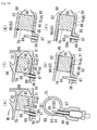
- compartment structure of the secondary air mixing chamber of the combustible gas generator is as follows. As shown in FIG. 9(A) , compartment plate placement faces 50 and 51 are formed in the dead end (bottom end portion) of the combustible gas generation catalyst chamber 11, a compartment plate 52 is placed in and fixed to the compartment plate placement faces 50 and 51, the secondary air mixing chamber 44 is comparted and formed on the dead end (bottom end portion) of the combustible gas generation catalyst chamber 11 by the compartment plate 52, a plurality of combustible gas outlet holes 54 maintained at specific intervals in the circumferential portion 53 of the compartment plate 52 in a peripheral direction thereof are opened, and the combustible gas 4 generated by using the combustible gas generation catalyst 13 is supplied to the secondary air mixing chamber 44 through the combustible gas outlet holes 54.
- the secondary air mixing chamber 44 can be formed simply and easily. Furthermore, the air-fuel mixture gas 23 introduced into the center portion of the combustible gas generation catalyst 13 through the air-fuel mixture gas supply throttle gap 20 passes through the combustible gas generation catalyst 13 without hindrance toward the plurality of combustible gas outlet holes 54 in the circumferential portion 53 of the compartment plate 52 placed in the dead end of the combustible gas generation catalyst chamber 11. Accordingly, the combustible gas 4 can be efficiently generated.
- the compartment plate placement face 50 of the two compartment plate placement faces 50 and 51 is the top end face of a ring-shaped compartment wall 57 to be described later, and the other compartment plate placement face 51 thereof is formed along the inner circumference of the chamber wall 55 of the secondary air mixing chamber 44.
- FIG. 9(B) is a modification example of the compartment structure of the secondary air mixing chamber.
- a combustible gas outlet gap 56 is formed along the circumferential portion 53 of the compartment plate 52 between the circumferential portion 53 of the compartment plate 52 and the chamber wall 55 of the secondary air mixing chamber 44, and the combustible gas 4 generated by using the combustible gas generation catalyst 13 is supplied to the secondary air mixing chamber 44 through the combustible gas outlet gap 56.
- the compartment plate 52 includes three protrusions 73 protruded in a radial direction, and the front ends of the three protrusions 73 come into contact with the chamber wall 55 of the secondary air mixing chamber 44, so that the movement of the compartment plate 52 in a diameter direction thereof is suppressed.
- a ring-shaped compartment wall 57 is installed at the center portion of the secondary air mixing chamber 44, a secondary air confluence chamber 58 on the circumference of the ring-shaped compartment wall 57 and secondary air mixing gas expansion chambers 59 and 59 within the ring-shaped compartment wall 57 are comparted by the ring-shaped compartment wall 57, the upper opening portions of the secondary air mixing gas expansion chambers 59 and 59 are closed by the compartment plate 52, a throttle hole 60 is opened at the inlet of the secondary air mixing gas expansion chamber 59, a secondary air mixing gas outlet 61 is opened at the outlet of the secondary air mixing gas expansion chamber 59, and the combustible gas 4 and the secondary air 48 are supplied from the combustible gas generation catalyst chamber 11 and the secondary air supply source 47 to the secondary air confluence chamber 58.
- the secondary air mixing gas 49 formed by joining the combustible gas 4 and the secondary air 48 in the secondary air confluence chamber 58 is formed, the secondary air mixing gas 49 is throttled by the throttle holes 60 and then spread while being expanded in the secondary air mixing gas expansion chamber 59, and the secondary air mixing gas 49 is supplied to the combustion catalyst 46 via the secondary air mixing gas outlet 61. Accordingly, the secondary air confluence chamber 58 and the secondary air mixing gas expansion chamber 59 can be formed simply and easily. Furthermore, catalyst combustion in the combustion catalyst 46 can be efficiently performed because a concentration distribution of the secondary air mixing gas 49 supplied to the combustion catalyst 46 becomes uniform.
- the structure of the exhaust pipe is as follows. As shown in FIG. 1 , the exhaust pipe 66 is mounted on an exhaust pipe mounting place 65 in the exhaust path, and the DPF casing 67 in which the DPF 5 is accommodated is disposed in the lower stream of the exhaust pipe 66. As shown in FIG. 1 , the exhaust pipe 66 is mounted on an exhaust pipe mounting place 65 in the exhaust path, and the DPF casing 67 in which the DPF 5 is accommodated is disposed in the lower stream of the exhaust pipe 66. As shown in FIG.
- an exhaust outlet passage 68 and a strained unit 69 protruded from the exhaust outlet passage 68 outwardly in the diameter direction of the exhaust outlet passage 68 are installed in the exhaust pipe mounting place 65, the passage starting end portion 71 of the exhaust passage 7 and the passage dead end 74 of a combustible gas guidance passage 70 are installed in parallel in the exhaust pipe 66, the central axial line 71a of the passage starting end portion 71 of the exhaust passage 7 complies with the central axial line 68a of the exhaust outlet passage 68, and the passage central axial line 74a of the passage dead end 74 of the combustible gas guidance passage 70 opens the combustible gas discharge port 6 at the boundary of the passage dead end 74 of the combustible gas guidance passage 70 and the passage starting end portion 71 of the exhaust passage 7 toward the strained unit 69.
- the combustible gas 4 flowing along the passage axial line 74a of the passage dead end 74 of the combustible gas guidance passage 70 flows toward the strained unit 69 and does not directly come into contact with the exhaust gas 8 passing through the exhaust passage 7, but the combustible gas 4 is gently discharged from the combustible gas discharge port 6 to the passage starting end portion 71 of the exhaust passage 7. For this reason, back pressure can become small because a deviation in the flow of the exhaust gas 8 by the combustible gas 4 is suppressed. Furthermore, as shown in FIG.
- the exhaust pipe 66 that is bent or straight on the side of the passage dead end 63 of the exhaust passage 7 can be selectively used, and a deviation in the exhaust gas 8 is suppressed even when the arrangement of the DPF casing 67 is changed. Accordingly, a difference in back pressure due to the difference of the shape of the exhaust pipe 66 is small and a constant exhaust gas performance is assured. For this reason, the degree of freedom in the arrangement of the DPF casing 67 can be increased by changing a shape on the side of the passage dead end 63 of the exhaust pipe 66.
- the exhaust pipe mounting place of the exhaust turbine 76 of the super charger 75 is used as the exhaust pipe mounting place 65
- the exhaust outlet passage of the exhaust turbine 76 is used as the exhaust outlet passage 68
- the waste gate valve 77 of the exhaust turbine 76 and a valve mounting unit 78 thereof are used as the strained unit 69. Accordingly, the exhaust pipe 66 can be mounted by using the super charger 77.
- the outlet-side end face 79 of the combustion catalyst 46 is spaced apart from the combustible gas discharge port 6 toward the starting end side of the combustible gas guidance passage 70.
- the fixing structure of the combustible catalyst is as follows. As shown in FIG. 10(A) , a secondary air mixing gas inlet chamber 81 is formed between the secondary air mixing gas outlet 61 of the secondary air mixing chamber 44 and the combustion catalyst chamber 45, a combustion catalyst reception portion 82 and a combustion catalyst stopper 83 are installed in the secondary air mixing gas inlet chamber 81 and the combustion catalyst chamber 45, and the combustion catalyst 46 is put in the combustion catalyst chamber 45 from the passage dead end 74 of the combustible gas guidance passage 70 toward the secondary air mixing gas inlet chamber 81.
- the combustion catalyst 46 can be easily fixed to the catalyst combustion chamber 45.
- the inner peripheral surface 88 of the secondary air mixing gas inlet chamber 81 has a taper form in which the inner peripheral surface 88 is enlarged and opened from the secondary air mixing gas outlet 61 toward the combustion catalyst chamber 45, and the inner peripheral surface 88 of the secondary air mixing gas inlet chamber 81 is used as the combustion catalyst reception portion 82. Accordingly, the secondary air mixing gas 49 flowed out from the secondary air mixing gas outlet 61 is widely diffused in the secondary air mixing gas inlet chamber 81 toward the inlet-side end face 80 of the combustion catalyst 46 and then introduced from the entire area of the inlet-side end face 80 of the combustion catalyst 46 to the combustion catalyst 46 smoothly. Accordingly, the combustible gas 4 within the secondary air mixing gas 49 can be efficiently burnt over the entire area of the combustion catalyst 46. Furthermore, it is not necessary to specially install the combustion catalyst reception portion 82.
- a pipe 90 is inserted into the sensor insertion hole 86, the combustion catalyst outlet-side temperature sensor 87 is inserted into the pipe 90 so that the combustion catalyst outlet-side temperature sensor 87 passes through the pipe 90, the sensor temperature sensing unit 89 is protruded from the insertion-side end 91 of the pipe 90, and the outlet-side end face 79 of the combustion catalyst 46 is received in the outer peripheral surface 92 of the insertion-side end 91 of the pipe 90.
- the insertion-side end 91 of the pipe 90 is used as the combustion catalyst stopper 83, and the sensor temperature sensing unit 89 of the combustion catalyst outlet-side temperature sensor 87 is spaced apart from the outlet-side end face 79 of the combustion catalyst 46 by means of the insertion-side end 91 of the pipe 90.
- a new insertion hole for mounting the stopper 83 on the passage wall 85 of the combustible gas guidance passage 70 needs not to be formed. Furthermore, a problem that heat is directly inputted from the outlet-side end face 79 of the combustion catalyst 46 to the sensor temperature sensing unit 89 or a problem that the outlet-side end face 79 of the combustion catalyst 46 comes into contact with the sensor temperature sensing unit 89 owing to a vibration of the engine can be prevented. Accordingly, damage to the sensor temperature sensing unit 89 of the combustion catalyst outlet-side temperature sensor 87 can be prevented.
- the passage wall 85 of the combustible gas guidance passage 70 is left in part of the inner end of the sensor insertion hole 86 and used as the pipe reception unit 93, and part of the insertion-side end face 94 of the pipe 90 is received in the pipe reception unit 93. Accordingly, since the pipe 90 does not unnecessarily enter the combustible gas guidance passage 70, a problem that the sensor temperature sensing unit 89 of the combustion catalyst outlet-side temperature sensor 87 is covered at the insertion-side end 91 of the pipe 90 can be prevented.
- FIGS. 10(C) to 10 (F) show modification examples of the fixing structure of the combustion catalyst.
- a first modification example shown in FIG. 10(C) shows that an adiabatic cushion material 96 is interposed between the combustion catalyst 46 and the chamber wall 62 of the combustion catalyst chamber 45, in the embodiments shown in FIGS. 10(A) and 10(B) .
- the adiabatic cushion material 96 is a sheet of glass wool.
- a second modification example shown in FIG. 10(D) shows that the adiabatic cushion material 96 is interposed between the combustion catalyst chamber 45 and the combustion catalyst 46, the adiabatic cushion material 96 is rubbed against and fixed to the chamber wall 62 of the combustion catalyst chamber 45, and the combustion catalyst 46 is rubbed against and fixed to the adiabatic cushion material 96 so that the adiabatic cushion material 96 is used as the combustion catalyst stopper 83.
- the catalyst activity and durability of the combustion catalyst 46 can be increased because a reduction in the temperature of the combustion catalyst 46 or an impact to the combustion catalyst 46 can be avoided by the adiabatic cushion material 96.
- a snap ring 98 is inwardly inserted into and fixed to the outlet of the combustion catalyst chamber 45, and the snap ring 98 is used as the combustion catalyst stopper 83.
- a sleeve 99 is press-fit from the passage dead end 74 of the combustible gas guidance passage 70 toward the combustion catalyst chamber 45, the sleeve 99 is rubbed against and fixed to the passage wall 85 of the combustible gas guidance passage 70, and the sleeve 99 is used as the combustion catalyst stopper 83.
- a sensor insertion through-hole 99a is formed in the sleeve 99, and the sensor temperature sensing unit 89 of the combustion catalyst outlet-side temperature sensor 87 is protruded into the sleeve 99 from the sensor insertion through-hole 99a.
- the combustion catalyst 46 can be robustly fixed in the catalyst combustion chamber 45.
- the chamber wall 95 of the secondary air mixing gas inlet chamber 81, the chamber wall 55 of the secondary air mixing chamber 44, and the ring-shaped compartment wall 57 are integrated into a molding product. Furthermore, the secondary air mixing gas outlet 61 penetrating a boundary wall 97 between the secondary air mixing gas inlet chamber 81 and the secondary air mixing gas expansion chamber 59 and the throttle holes 60 and 60 penetrating the ring-shaped compartment wall 57 are formed by a series of straight drilling processes from the passage dead end 74 of the combustible gas guidance passage 70 toward the secondary air confluence chamber 58 via the secondary air mixing gas inlet chamber 81 and the secondary air mixing gas expansion chamber 59. Accordingly, the secondary air mixing gas outlet 61 and the throttle holes 60 and 60 can be formed simply and easily.
- An engine ECU 102 that is a controller shown in FIG. 1 includes a PM accumulation amount estimation device 101 and a PM regeneration controller 111.
- the engine ECU is an abbreviation of an engine electronic control unit.
- the PM accumulation amount estimation device 101 is a specific operation unit of the engine ECU 102 that estimates a PM accumulation amount from map data which is experimentally calculated in advance on the basis of an engine load, the number of rotations of the engine, an exhaust gas temperature detected by a DPF upper stream-side exhaust temperature sensor 103, a DPF (5) upper stream-side exhaust gas pressure by a DPF upper stream-side exhaust gas pressure sensor 104, and a difference in the pressure between the upper stream and the lower stream of the DPF 5 by a difference pressure sensor 105, etc.
- the PM regeneration controller 111 heats the heater 25 and drives a liquid fuel pump 107, an air supply pump 108, and a secondary air supply pump 109. Accordingly, the liquid fuel 2 and the air 3 are supplied to the air-fuel mixing chamber 12, the combustible gas 4 is generated by using the combustible gas generation catalyst 13, the secondary air mixing gas 49 is formed in the secondary air mixing chamber 44, a temperature of the combustible gas 4 is raised by the combustion catalyst 46, and the combustible gas 4 having a raised temperature is discharged from the combustible gas discharge port 6 to the exhaust passage 7 in the upper stream of the DPF 5.
- the PM regeneration controller 111 meters the amount of the liquid fuel supplied by the liquid fuel pump 107 or the amount of the air supplied by the air pump 108 on the basis of a temperature of the combustible gas generation catalyst 13, detected by the combustible gas generation catalyst temperature sensor 106, and meters the amount of the secondary air supplied by the secondary air pump 109 on the basis of a temperature of the combustible gas 4 on the outlet side of the combustion catalyst 46, detected by the combustion catalyst outlet-side temperature sensor 87.
- the PM regeneration controller 111 meters the amount of the secondary air supplied by the secondary air pump 109, raises a temperature of the combustible gas 4, and raises a temperature of the exhaust gas 12 in order to activate the DOC 10.
- the PM regeneration controller 111 stops the supply of the combustible gas 4 to the exhaust gas 8.
- the DPF regeneration controller 111 performs control as follows. As shown in FIG. 1 , in controlling the supply of the air 3 and the liquid fuel 2 to the air-fuel mixing chamber 12 through the DPF regeneration controller 111, when a combustible gas 4 starts being generated, the DPF regeneration controller 111 initiates the supply of the air 3 and the liquid fuel 2 on the basis of a lapse of a specific pre-heating time from the start of the generation of heat of the heater 25 not on the basis of a combustible gas generation catalyst temperature. Accordingly, the time unnecessarily taken until the supply of the air 3 and the liquid fuel 2 is initiated after the generation of heat of the heater 25 is initiated does not exist, and the generation of a combustible gas 4 can be smoothly initiated.
- the reason is as follows. That is, a thermistor and the like which is inserted into the combustible gas generation catalyst 13 is used as a combustible gas generation catalyst temperature sensor 106, but a combustible gas generation catalyst temperature sensor 106 cannot be brought in contact with the combustible gas generation catalyst 13 from a viewpoint of prevention of damage. Thus, if the supply of the air 3 and the liquid fuel 2 after the generation of heat of the heater 25 is initiated is initiated on the basis of a combustible gas generation catalyst temperature, it is difficult for the combustible gas generation catalyst temperature sensor 106 to precisely detect temperature of the combustible gas generation catalyst 13 which is relatively low after the heater starts generating heat.
- the start of the supply of the liquid fuel 2 after the generation of heat of the heater 25 is started is performed not on the basis of a combustible gas generation catalyst temperature, but on the basis of a lapse of a specific pre-heating time after the generation of heat of the heater 25 is started and a necessary pre-heating time is previously calculated experimentally, the generation of a combustible gas 4 can be smoothly started because it is not necessary to unnecessarily wait for a long pre-heating time until the supply of the liquid fuel 2 is initiated after the generation of heat of the heater 25 is started.
- the air 3 for liquid fuel purge is supplied without supplying the liquid fuel 2 to the combustible gas generator 1, and the liquid fuel 2 remaining in the combustible gas generation catalyst 13 is purged from the combustible gas generation catalyst 13 by using the air 3, as the combustible gas. Accordingly, when the regeneration processing of the DPF is subsequently initiated, the combustible gas generation catalyst 13 does not remain wet with the liquid fuel 2. Thus, the generation of a combustible gas 4 can be smoothly initiated because the temperature of the combustible gas generation catalyst 13 rapidly rises.
- the amount of supply of the air 3 is increased (S16) and the temperature of the combustible gas generation catalyst does not rise for all that, it means that most of the liquid fuel 2 does not remain in the combustible gas generation catalyst 13, and thus the supply of the air 3 is stopped (S18) so that the liquid fuel purge processing is terminated.
- the liquid fuel purge processing is rapidly terminated.
- a flow of processing by the DPF regeneration controller 111 is as follows. As shown in FIG. 14 , whether a PM accumulation estimation value has reached a specific DPF regeneration requirement value is determined at step S1. If the determination is yes, the generation of heat of the heater 25 is initiated at step S2. Whether a specific pre-heating time has elapsed is then determined at step S3. If the determination is yes, the supply of the air 3 and the liquid fuel 2 is initiated at step S4. Whether temperature of a combustible gas generation catalyst has exceeded a gas generation temperature or not is determined at step S5. If the determination is yes, the generation of heat of the heater 25 is finished at step S6. Whether the PM accumulation estimation value has reached a specific DPF regeneration end value or not is determined at step S7. If the determination is yes, the supply of the air 3 and the liquid fuel is finished at step S8.
- a DOC outlet temperature exceeds a purge gas processing temperature (catalyst activation temperature of a DOC) or not is determined at step S9. If the determination is yes, whether temperature of a combustible gas generation catalyst exceeds a gas generation temperature or not is determined at step S10. If the determination is yes, the supply of the air 3 for liquid fuel purge is initiated at step S11, and whether the temperature of the combustible gas generation catalyst rises or not is determined at step S12.
- step S14 the air continues to be supplied at step S13, and whether the temperature of the combustible gas generation catalyst exceeds a purge stop temperature (temperature at which thermal damage due to the overheating of a DPF can be suppressed) or not is determined at step S14. If the determination is yes, the supply of the air is stopped at step S15, and the process returns to step S9. If the determination at step S14 is no, the process returns to step S13. If the determination at step S12 is no, the amount of supply of the air 3 is increased at step S16, and whether the temperature of the combustible gas generation catalyst rises or not is determined at step S17. If the determination is yes, the process proceeds to step S13. If the determination is no, the supply of the air 3 is stopped at step S18, and thus the liquid fuel purge processing is terminated.
- a purge stop temperature temperature at which thermal damage due to the overheating of a DPF can be suppressed
- the DPF regeneration controller 111 calculates the amount of supply of the air 3 and the liquid fuel 2 to the combustible gas generator 1 on the basis of the upper stream-side exhaust temperature of the DOC 100. Accordingly, a change of the upper stream-side exhaust temperature of the DOC 100 due to a change of a load or a change of rotation is reflected in the calculation of the amount of supply of the air 3 and the liquid fuel 2 to the combustible gas generator 1 without change before being subject to the heat storage function of the DOC 100, and the calculated value rapidly corresponds to a change of temperature of an exhaust gas. Accordingly, the amount of generation of the combustible gas 4 becomes proper, and the regeneration efficiency of the DPF 5 can be increased.
- the amount of supply of the air 3 and the liquid fuel 2 to the combustible gas generator 1 is calculated on the basis of the upper stream-side exhaust temperature of the DOC 100 and the number of rotations of the engine. Accordingly, calculation based on the amount of fuel jet or the amount of an intake from a fuel jet valve to a combustion chamber becomes unnecessary. Accordingly, the exhaust gas treatment device can also be used in a diesel engine equipped with a machine cam type fuel jet pump or a diesel engine not equipped with an air flow sensor.
- the calculation of the amount of supply of the air 3 and the liquid fuel 2 to the combustible gas generator 1 using the DPF regeneration controller 111 is performed on the basis of map data for the amount of supply that is experimentally calculated in relation to the upper stream-side exhaust temperature of the DOC 100 and the number of rotations of the engine.
Landscapes
- Engineering & Computer Science (AREA)
- Chemical & Material Sciences (AREA)
- Mechanical Engineering (AREA)
- General Engineering & Computer Science (AREA)
- Combustion & Propulsion (AREA)
- Chemical Kinetics & Catalysis (AREA)
- Health & Medical Sciences (AREA)
- Environmental & Geological Engineering (AREA)
- Toxicology (AREA)
- Materials Engineering (AREA)
- Biomedical Technology (AREA)
- Analytical Chemistry (AREA)
- General Chemical & Material Sciences (AREA)
- Oil, Petroleum & Natural Gas (AREA)
- Processes For Solid Components From Exhaust (AREA)
- Exhaust Gas After Treatment (AREA)
- Filtering Of Dispersed Particles In Gases (AREA)
Abstract
Description
- The present invention relates to an exhaust gas treatment device for a diesel engine and, more particularly, to an exhaust gas treatment device for a diesel engine, which can smoothly start the generation of a combustible gas and also reduce the size of a combustible gas generator.
From among the terms of this specification and claims, a DPF is an abbreviation of a diesel particulate filter, and a PM is an abbreviation of a particulate matter included in an exhaust gas, and a DOC means a diesel oxidization catalyst. - There is a conventional device in which a combustible gas is generated by a combustible gas generator, the combustible gas is discharged from a combustible gas discharge port to an exhaust passage in the upper stream of a DPF, a temperature of an exhaust gas is raised by combustion heat generated by burning the combustible gas using oxygen in the exhaust gas, and a PM accumulated in the DPF is burnt and removed by the heat of the exhaust gas (refer to Patent Document 1).
- This type of a device is advantageous in that the PM accumulated in the DPF can be burnt and removed by raising the temperature of the exhaust gas by using the combustible gas even when the temperature of the exhaust gas is low.
- The conventional technology, however, is problematic in that a thermal conduction plate and the central wall of an air-fuel mixing chamber are interposed between the heat-dissipating outer peripheral surface of a heater and the air-fuel mixing chamber and thus heat is indirectly radiated from the heat-dissipating outer peripheral surface of the heater to the air-fuel mixing chamber sequentially through the thermal conduction plate and the central wall of the air-fuel mixing chamber when the generation of the combustible gas is started.
-
- Patent Document 1: Japanese Unexamined Patent Publication No.
2008-19796 FIG. 1 ) - When the generation of a combustible gas is started, heat is indirectly radiated from the heat-dissipating outer peripheral surface of the heater to the air-fuel mixing chamber sequentially through the thermal conduction plate and the central wall of the air-fuel mixing chamber. Accordingly, it is difficult for the heat of the heater to be transferred to the air-fuel mixing chamber and the generation of the combustible gas may not be smoothly started because the formation of an air-fuel mixture gas is delayed.
- There is the case in which the size of the combustible gas generator is increased because the thermal conduction plate or the inner circumferential wall of the air-fuel mixing chamber is interposed between the heater and the air-fuel mixing chamber.
- An object of the present invention is to provide an exhaust gas treatment device for a diesel engine, which can smoothly start the generation of a combustible gas and also reduce the size of a combustible gas generator.
- The characteristic of an invention according to
claim 1 is as follows.
As illustrated inFIG. 1 , in the exhaust gas treatment device of a diesel engine in which acombustible gas 4 is generated by acombustible gas generator 1, thecombustible gas 4 is discharged from a combustiblegas discharge port 6 to anexhaust passage 7 in the upper stream of aDPF 5, thecombustible gas 4 is burnt by oxygen within anexhaust gas 8, a temperature of theexhaust gas 8 is raised by the heat of the combustion, and a PM accumulated in theDPF 5 is burnt and removed by the heat of theexhaust gas 8,
as illustrated inFIG. 2 , a combustible gasgeneration catalyst chamber 11 is installed in thecombustible gas generator 1, a combustiblegas generation catalyst 13 is accommodated in the combustible gasgeneration catalyst chamber 11, a ring-shaped wall 14 is disposed in the starting end portion of the combustible gasgeneration catalyst chamber 11, an air-fuel mixing chamber 12 is formed on the inside of the ring-shaped wall 14, andair 3 andliquid fuel 2 are supplied to the air-fuel mixing chamber 12 so that an air-fuel mixture gas 23 is formed in the air-fuel mixing chamber 12, the air-fuel mixture gas 23 is supplied to the combustiblegas generation catalyst 13, and thecombustible gas 4 is generated using the combustiblegas generation catalyst 13, and as illustrated inFIGS. 3(A) and 3(B) ,FIGS. 4(A) and 4(B) , andFIG. 7 acore member 15 is inwardly inserted into the center portion of the ring-shaped wall 14 so that the air-fuel mixing chamber 12 is formed between the innerperipheral surface 16 of the ring-shaped wall 14 and the outerperipheral surface 18 of thecore member 15, and the air-fuel mixture gas 23 of the air-fuel mixing chamber 12 is supplied from the dead end of the air-fuel mixing chamber 12 to a portion near the center portion of the combustiblegas generation catalyst 13, and the heat-dissipating outerperipheral surface 26 of aheater 25 is exposed to the air-fuel mixing chamber 12 by using theheater 25 as thecore member 15, and when thecombustible gas 4 starts being generated, heat is directly radiated from the heat-dissipating outerperipheral surface 26 of theheater 25 to the air-fuel mixing chamber 12,
as illustrated inFIGS. 3(A) and 3(B) ,FIGS. 4(A) and 4(B) ,FIG. 7 , an air-fuel mixturegas inlet face 27 is formed on the inner circumferential face of the combustiblegas generation catalyst 13 of a ring shape, a liquidfuel retention material 28 is made along the air-fuel mixturegas inlet face 27, and thecore member 15 is inserted into the central portion of the liquidfuel retention material 28 so that the air-fuel mixture gas 23 of the air-fuel mixing chamber 12 is introduced from the dead end of the air-fuel mixing chamber 12 to the air-fuel mixturegas inlet face 27 near the center of the combustiblegas generation catalyst 13 through the liquidfuel retention material 28, and
the heat-dissipation outerperipheral surface 26 of theheater 25 used as thecore member 15 is exposed toward the liquidfuel retention material 28, so that when thecombustible gas 4 starts being generated, heat is radiated from the heat-dissipation outerperipheral surface 26 of theheater 25 to the liquidfuel retention material 28. - The invention according to
claim 1 exhibits the following effects. - As illustrated in
FIGS. 3(A) and 3(B) ,FIGS. 4(A) and 4(B) , andFIG. 7 , the heat-dissipating outerperipheral surface 26 of theheater 25 is exposed to the air-fuel mixing chamber 12 by using theheater 25 as thecore member 15 and, when thecombustible gas 4 starts being generated, the heat is directly radiated from the heat-dissipating outerperipheral surface 26 of theheater 25 to the air-fuel mixing chamber 12. Accordingly, the generation of thecombustible gas 4 can be smoothly started because the heat of theheater 25 is rapidly transferred to the air-fuel mixing chamber 12 and the air-fuel mixture gas 23 is rapidly formed. - The size of the
combustible gas generator 1 can be reduced because an intervening substance does not exist between theheater 25 and the air-fuel mixing chamber 12, as illustrated inFIGS. 3(A) and 3(B) ,FIGS. 4(A) and 4(B) , andFIG. 7 . - As illustrated in
FIGS. 3(A) and 3(B) ,FIGS. 4(A) and 4(B) , andFIG. 7 , since the air-fuel mixture gas 23 of the air-fuel mixing chamber 12 is supplied from the dead end of the air-fuel mixing chamber 12 to a portion near the center portion of the combustiblegas generation catalyst 13, it is difficult for heat to escape, a high temperature state is maintained, and thecombustible gas 4 can be efficiently generated in the portion near the center portion of the combustiblegas generation catalyst 13 where high catalyst activity is obtained. - As illustrated in
FIGS. 3(A) and 3(B) ,FIGS. 4(A) and 4(B) , andFIG. 7 , when thecombustible gas 4 starts being generated, heat is radiated from the heat-dissipating outerperipheral surface 26 of theheater 25 to the liquidfuel retention material 28, and thus the heat of theheater 25 is concentratively transferred to theliquid fuel 2 maintained in the liquidfuel retention material 28. Accordingly, the generation of thecombustible gas 4 can be smoothly initiated because the temperature of theliquid fuel 2 rapidly rises. - The size of the
combustible gas generator 1 can be reduced because an intervening substance does not need to be installed between theheater 25 and the liquidfuel retention material 28, as illustrated inFIGS. 3(A) and 3(B) ,FIGS. 4(A) and 4(B) , andFIG. 7 . - As illustrated in
FIGS. 3(A) and 3(B) ,FIGS. 4(A) and 4(B) , andFIG. 7 , the air-fuel mixture gas 23 of the air-fuel mixing chamber 12 is introduced into the combustiblegas generation catalyst 13 through the liquidfuel retention material 28. Accordingly, thermal damage to the combustiblegas generation catalyst 13 or the ring-shaped wall 14 can be prevented because the occurrence of flaming combustion of the air-fuel mixture gas 23 is suppressed by the quenching function of the liquidfuel retention material 28. - As illustrated in
FIGS. 3(A) and 3(B) ,FIGS. 4(A) and 4(B) ,FIG. 7 , the air-fuel mixture gas 23 of the air-fuel mixing chamber 12 is introduced from the dead end of the air-fuel mixing chamber 12 to the air-fuel mixturegas inlet face 27 near the center portion of the combustiblegas generation catalyst 13 through the liquidfuel retention material 28, thereby making heat difficult to escape and maintaining a high temperature state. Accordingly, thecombustible gas 4 can be efficiently generated at the air-fuel mixturegas inlet face 27 near the center portion of the combustiblegas generation catalyst 13 where high catalyst activity is obtained. - The invention according to
claim 2 exhibits the following effect in addition to the effect of the invention according toclaim 1. - As shown in
FIG. 1 , when thecombustible gas 4 starts being generated, theDPF regeneration controller 111 initiates the supply of theair 3 and theliquid fuel 2 on the basis of a lapse of a specific pre-heating time from the start of the generation of heat of theheater 25 not on the basis of a combustible gas generation catalyst temperature. Accordingly, the time unnecessarily taken until the supply of theair 3 and theliquid fuel 2 is initiated after the generation of heat of theheater 25 is initiated does not exist, and the generation of acombustible gas 4 can be smoothly initiated. - The reason is as follows.
- That is, a thermistor and the like which is inserted into the combustible
gas generation catalyst 13 is used as a combustible gas generationcatalyst temperature sensor 106, but a combustible gas generationcatalyst temperature sensor 106 cannot be brought in contact with the combustiblegas generation catalyst 13 from a viewpoint of prevention of damage. Thus, if the supply of theair 3 and theliquid fuel 2 after the generation of heat of theheater 25 is initiated is initiated on the basis of a combustible gas generation catalyst temperature, it is difficult for the combustible gas generationcatalyst temperature sensor 106 to precisely detect temperature of the combustiblegas generation catalyst 13 which is relatively low after the heater starts generating heat. Accordingly, it is necessary to wait for the start of the supply of theair 3 and theliquid fuel 2 until the combustible gas generationcatalyst temperature sensor 106 detects a high detection temperature at which the combustiblegas generation catalyst 13 is certainly assumed to have reached a combustible gas generation temperature. - Compared with this, if the start of the supply of the
liquid fuel 2 after the generation of heat of theheater 25 is started is performed not on the basis of a combustible gas generation catalyst temperature, but on the basis of a lapse of a specific pre-heating time after the generation of heat of theheater 25 is started and a necessary pre-heating time is previously calculated experimentally, the generation of acombustible gas 4 can be smoothly started because it is not necessary to unnecessarily wait for a long pre-heating time until the supply of theliquid fuel 2 is initiated after the generation of heat of theheater 25 is started. - The invention according to
claim 3 exhibits the following effects in addition to the effects of the invention according toclaim - As illustrated in
FIGS. 3 (A) and 3(B) ,FIGS. 4 (A) and 4(B), andFIG. 7 , an air-fuel mixture gassupply throttle part 17 is installed in the dead end of the innerperipheral surface 16 of the ring-shaped wall 14, and an air-fuel mixture gassupply throttle gap 20 is formed between the air-fuel mixture gassupply throttle part 17 and the outerperipheral surface 18 of thecore member 15. Accordingly, thermal damage to the combustiblegas generation catalyst 13 or the ring-shaped wall 14 can be prevented because the occurrence of flaming combustion of the air-fuel mixture gas 23 is suppressed by the quenching function of the air-fuel mixture gassupply throttle gap 20. - As illustrated in
FIGS. 3(A) and 3(B) ,FIGS. 4(A) and 4(B) , andFIG. 7 , the innerperipheral surface 16 of the ring-shaped wall 14 and the outerperipheral surface 18 of thecore member 15 are mutually positioned and the air-fuel mixture gassupply throttle part 17 and the outerperipheral surface 18 of thecore member 15 are also mutually positioned, through aspacer protrusion 29. Accordingly, the assembly of thecombustible gas generator 1 can be easily performed because this positioning can be accurately performed without using a tool. - The invention according to
claim 4 exhibits the following effects in addition to the effects of the invention according toclaim 3. - As illustrated in
FIGS. 3(A) and 3(B) ,FIGS. 4(A) and 4(B) , andFIG. 7 , a liquidfuel retention material 28 made along the air-fuel mixturegas inlet face 27 of the combustiblegas generation catalyst 13 and the outerperipheral surface 18 of thecore member 15 are mutually positioned through thecircumferential wall 10 of the combustible gasgeneration catalyst chamber 11, the ring-shaped wall 14, and thespacer protrusion 29. Accordingly, the assembly of thecombustible gas generator 1 can be easily performed because this positioning can be accurately performed without using a tool. - The invention according to claim 5 exhibits the following effect in addition to the effects of the invention according to any one of
claims 1 to 4. - As illustrated in
FIGS. 3(A) and 3(B) ,FIGS. 4(A) and 4(B) , andFIG. 7 , a positionadjustment protrusion unit 30 placed more inward than thesubject placement face 32 is installed in the dead end of the ring-shapedwall 14, and the positionadjustment protrusion unit 30 is inwardly inserted into the starting end portion of thecircumferential wall 10 of the combustible gasgeneration catalyst chamber 11. Accordingly, the leakage of gas between aplacement face 31 and thesubject placement face 32 of the ring-shapedwall 14 can be suppressed because the leakage of the air-fuel mixture gas 23 or thecombustible gas 4 from the starting end portion of the combustible gasgeneration catalyst chamber 11 is suppressed by the tight fit of the positionadjustment protrusion unit 30. - (An invention according to claim 6)
The invention according to claim 6 exhibits the following effect in addition to the effects of the invention according toclaim 5. - As illustrated in
FIGS. 4(A) and 4(B) , anadiabatic space 34 is formed in the positionadjustment protrusion unit 30 between the combustiblegas generation catalyst 13 and a mountingbolt 33. Accordingly, the transfer of heat generated by using the combustiblegas generation catalyst 13 is hindered in theadiabatic space 34, and the thermal expansion of the mountingbolt 33 is suppressed. Consequently, a reduction in the axial force of the mountingbolt 33 can be suppressed. - (An invention according to claim 7)
The invention according to claim 7 exhibits the following effect in addition to the effects of the invention according toclaim 6. - As illustrated in
FIG. 4(B) , theadiabatic space 34 is concavely formed in the outer peripheral surface of the positionadjustment protrusion unit 30, asealant 35 is placed in theadiabatic space 34, and thesealant 35 is sealed between the positionadjustment protrusion unit 30 and thecircumferential wall 10 of the combustible gasgeneration catalyst chamber 11. This makes a gasket unnecessary between theplacement face 31 of the combustible gasgeneration catalyst chamber 11 and thesubject placement face 32 of the ring-shapedwall 14. Accordingly, a reduction in the axial force of the mountingbolt 33 resulting from a reduction in the elastic force of the gasket can be suppressed. - (An invention according to claim 8)
The invention according to claim 8 exhibits the following effect in addition to the effects of the invention according to any one ofclaims 1 to 7. - As illustrated in
FIGS. 5(A) and 5(B) ,FIGS. 6(A) to 6(C) ,FIGS. 8(A) to 8(D) , a plurality ofliquid fuel inlets 42 andliquid fuel outlets 36 are formed at specific intervals in thegasket 40 in a peripheral direction thereof, theliquid fuel outlets 36 are drawn from the respectiveliquid fuel inlets 42 toward the inside of thegasket 40, a liquidfuel guidance groove 41 is concavely formed in any one of the cover placement face 38 of the ring-shapedwall 14 and thesubject placement face 39 of thecover 37 in a peripheral direction thereof, the respectiveliquid fuel inlets 42 are made to communicate with the opening of the liquidfuel guidance groove 41, and theliquid fuel 2 supplied to the liquidfuel guidance groove 41 is flowed out from theliquid fuel outlets 36 to the air-fuel mixing chamber 12 through the respectiveliquid fuel inlets 42. Accordingly, the ring-shapedwall 14 can be easily processed as compared with the case in which a liquid fuel guidance passage or a liquid fuel outlet is formed in the ring-shapedwall 14. - (An invention according to claim 9)
The invention according to claim 9 exhibits the following effect in addition to the effects of the invention according to any one ofclaims 1 to 8. - As illustrated in
FIGS. 5(A) and 5(B) andFIGS. 6(A) to 6(C) , the plurality ofair inlets 42b and theair outlets 36b are installed at specific intervals in thegasket 40 in a peripheral direction thereof, theair outlets 36b are drawn from therespective air inlets 42b toward the inside of thegasket 40, anair guidance groove 41b is concavely formed in any one of the cover placement face 38 of the ring-shapedwall 14 and thesubject placement face 39 of thecover 37 in a peripheral direction thereof, therespective air inlets 42b are made to communicate with the opening of theair guidance groove 41b, and theair 3 supplied to theair guidance groove 41b is flowed out from theair outlets 36b to the air-fuel mixing chamber 12 through therespective air inlets 42b. Accordingly, the ring-shapedwall 14 can be easily processed as compared with the case in which an air guidance passage or an air outlet is formed in the ring-shapedwall 14. - The invention according to claim 10 exhibits the following effects in addition to the effects of the invention according to any one of
claims 1 to 9. - As illustrated in
FIGS. 3(A) and 3(B) ,FIGS. 4(A) and 4(B) , andFIG. 7 , the plurality ofliquid fuel outlets 36 is formed at specific intervals along the upper circumferential portion of the innerperipheral surface 16 of the ring-shapedwall 14 in a peripheral direction thereof, and theliquid fuel 2 flowed out from the respectiveliquid fuel outlets 36 is made to flow by self-weight along the innerperipheral surface 16 of the ring-shapedwall 14. Accordingly, a plurality of flows of theliquid fuel 2 flowing along the innerperipheral surface 16 of the ring-shapedwall 14 come in contact withair 3, thus becoming the air-fuel mixture gas 23. Accordingly, a concentration distribution of the air-fuel mixture gas 23 becomes uniform and thus the generation of thecombustible gas 4 can be accelerated. - As illustrated in
FIGS. 3(A) and 3(B) ,FIGS. 4(A) and 4(B) , andFIG. 7 , the innerperipheral surface 16 of the ring-shapedwall 14 has a taper form in which the diameter of the innerperipheral surface 16 is reduced toward a lower dead end. Accordingly, the air-fuel mixture gas 23 can be formed without a hindrance because theliquid fuel 2 flows along the innerperipheral surface 16 of the ring-shapedwall 14 by self-weight even when thecombustible gas generator 1 is inclined. - The invention according to claim 11 exhibits the following effect in addition to the effects of the invention according to any one of
claims 1 to 10. - As illustrated in
FIG. 2 , when the secondaryair mixing gas 49 passes through thecombustible catalyst 46, part of thecombustible gas 4 is subject to catalyst combustion by means of thesecondary air 48, the temperature of the remainder of thecombustible gas 4 passing through thecombustion catalyst 46 is raised by heat of the combustion, and thecombustible gas 4 having a raised temperature is discharged from the combustiblegas discharge port 6 to theexhaust passage 7. Accordingly, thecombustible gas 4 can be burnt by oxygen within theexhaust gas 8 because thecombustible gas 4 is ignited even when a temperature of theexhaust gas 8 is low. - The invention according to
claim 12 has the following effects in addition to the effects of the invention according toclaim 11. - As illustrated in
FIG. 9(A) , compartment plate placement faces 50 and 51 are formed in the dead end of the combustible gasgeneration catalyst chamber 11, acompartment plate 52 is placed in and fixed to the compartment plate placement faces 50 and 51, and the secondaryair mixing chamber 44 is comparted and formed on the lower side of the combustible gasgeneration catalyst chamber 11 by thecompartment plate 52. Accordingly, the secondaryair mixing chamber 44 can be simply formed. - As illustrated in
FIG. 9(A) , a plurality of combustible gas outlet holes 54 maintained at specific intervals in thecircumferential portion 53 of thecompartment plate 52 in a peripheral direction thereof are opened, and thecombustible gas 4 generated by using the combustiblegas generation catalyst 13 is supplied to the secondaryair mixing chamber 44 through the combustible gas outlet holes 54. Accordingly, the air-fuel mixture gas 23 introduced into the center portion of the combustiblegas generation catalyst 13 through the air-fuel mixture gassupply throttle gap 20 passes evenly through the combustiblegas generation catalyst 13 toward a plurality of combustible gas outlet holes 54 in thecircumferential portion 53 of thecompartment plate 52 in the dead end of the combustible gasgeneration catalyst chamber 11, thereby being capable of efficiently generating thecombustible gas 4. - The invention according to claim 13 exhibits the following effects in addition to the effects of the invention according to
claim 11. - As illustrated in
FIG. 9(B) , the compartment plate placement faces 50 and 51 are formed in the dead end of the combustible gasgeneration catalyst chamber 11, thecompartment plate 52 is placed in and fixed to the compartment plate placement faces 50 and 51, and the secondaryair mixing chamber 44 is comparted and formed on the lower side of the combustible gasgeneration catalyst chamber 11 by thecompartment plate 52. Accordingly, the secondaryair mixing chamber 44 can be simply formed. - As illustrated in
FIG. 9(B) , a combustiblegas outlet gap 56 is formed along thecircumferential portion 53 of thecompartment plate 52 between thecircumferential portion 53 of thecompartment plate 52 and thechamber wall 55 of the secondaryair mixing chamber 44, and thecombustible gas 4 generated by using the combustiblegas generation catalyst 13 is supplied to the secondaryair mixing chamber 44 through the combustiblegas outlet gap 56. Accordingly, the air-fuel mixture gas 23 introduced into the center portion of the combustiblegas generation catalyst 13 through the air-fuel mixture gassupply throttle gap 20 passes evenly through the combustiblegas generation catalyst 13 toward the combustiblegas outlet gap 56 along thecircumferential portion 53 of thecompartment plate 52 in the dead end of the combustible gasgeneration catalyst chamber 11, thereby being capable of efficiently generating thecombustible gas 4. - The invention according to claim 14 exhibits the following effects in addition to the effects of the invention according to claim 12 or 13.
- As illustrated in
FIGS. 9 (A) and 9(B) , a ring-shapedcompartment wall 57 is installed at the center portion of the secondaryair mixing chamber 44, a secondaryair confluence chamber 58 on the circumference of the ring-shapedcompartment wall 57 and secondary air mixinggas expansion chambers compartment wall 57 are comparted by the ring-shapedcompartment wall 57, the openings of the secondary air mixinggas expansion chambers compartment plate 52, athrottle hole 60 is opened at the inlet of the secondary air mixinggas expansion chamber 59, and a secondary air mixinggas outlet 61 is opened at the outlet of the secondary air mixinggas expansion chamber 59. Accordingly, the secondaryair confluence chamber 58 and the secondary air mixinggas expansion chamber 59 can be formed simply and easily. - As illustrated in
FIGS. 9(A) and 9(B) , thecombustible gas 4 and thesecondary air 48 are supplied from the combustible gasgeneration catalyst chamber 11 and the secondary air supply source 47 to the secondaryair confluence chamber 58. Accordingly, the secondaryair mixing gas 49 formed by joining thecombustible gas 4 and thesecondary air 48 in the secondaryair confluence chamber 58 is formed, the secondaryair mixing gas 49 is throttled by the throttle holes 60 and then diffused while being expanded in the secondary air mixinggas expansion chamber 59, and the secondaryair mixing gas 49 is supplied to thecombustion catalyst 46 via the secondary air mixinggas outlet 61. Consequently, catalyst combustion in thecombustion catalyst 46 can be efficiently performed because a concentration distribution of the secondaryair mixing gas 49 supplied to thecombustion catalyst 46 becomes uniform. -
-
FIG. 1 is a diagram of an exhaust gas treatment device for a diesel engine according to an embodiment of the present invention. -
FIG. 2 is a longitudinal sectional view of an exhaust pipe including the combustible gas generator of the device shown inFIG. 1 . -
FIG. 3 is a diagram illustrating the assembly structure of the combustible gas generator shown inFIG. 2 , whereinFIG. 3(A) is a partial enlarged view seen from an arrow IIIA ofFIG. 2 andFIG. 3(B) is a diagram of a first modification example, corresponding toFIG. 3(A) . -
FIG. 4 is a diagram illustrating another modification example of the assembly structure of the combustible gas generator, whereinFIG. 4(A) is a diagram of a second modification example, corresponding toFIG. 3(A) , andFIG. 4 (B) is a diagram of a third modification example, corresponding toFIG. 3(A) . -
FIG. 5 is a diagram illustrating a supply structure for liquid fuel and the like to the air-fuel mixing chamber of the combustible gas generator shown inFIG. 2 , whereinFIG. 5 (A) is a cross-sectional view taken along a line VA-VA inFIG. 2 andFIG. 5(B) is a cross-sectional view taken along a line B-B inFIG. 5(A) . -
FIG. 6 is an explanatory diagram of a part used in the supply structure for liquid fuel and the like to the air-fuel mixing chamber shown inFIG. 5 , whereinFIG. 6(A) is a plan view of a ring-shaped wall having a core member inserted therein,FIG. 6(B) is a plan view of a lower gasket, andFIG. 6(C) is a plan view of an upper gasket. -
FIG. 7 is a diagram illustrating a first modification example of the supply structure for liquid fuel and the like to the air-fuel mixing chamber shown inFIG. 5 , corresponding toFIG. 3(A) . -
FIG. 8 is a diagram illustrating a modification example of the supply structure for liquid fuel and the like to the air-fuel mixing chamber shown inFIG. 5 , whereinFIG. 8(A) is a diagram of a first modification example, corresponding toFIG. 5(A) ,FIG. 8(B) is a cross-sectional view taken along a line B-B inFIG. 8(A), FIG. 8(C) is a diagram of a second modification example, corresponding toFIG. 8(B), and FIG. 8(D) is a longitudinal sectional view of the second modification example ofFIG. 8(C) in another part. -
FIG. 9 is a diagram illustrating the compartment structure of the secondary air mixing chamber of the combustible gas generator shown inFIG. 2 , whereinFIG. 9(A) is a cross-sectional view taken along a line IXA-IXA inFIG. 2 andFIG. 9(B) is a diagram of a modification example, corresponding toFIG. 9(A) . -
FIG. 10 is a diagram illustrating the fixing structure of the combustible catalyst of the exhaust pipe shown inFIG. 2 , whereinFIG. 10 (A) is an enlarged view of major parts inFIG. 2 ,FIG. 10(B) is a cross-sectional view taken along a line B-B inFIG. 10(A), FIG. 10 (C) is a diagram of a first modification example, corresponding toFIG. 10(A), FIG. 10(D) is a diagram of a second modification example, corresponding toFIG. 10(A), FIG. 10(E) is a diagram of a third modification example, corresponding toFIG. 10(A), and FIG. 10(F) is a diagram of a fourth modification example, corresponding toFIG. 10(A) . -
FIG. 11 is a side view of major parts of a diesel engine including the exhaust gas treatment device shown inFIG. 1 . -
FIG. 12 is a plan view of major parts of the diesel engine including the exhaust gas treatment device shown inFIG. 1 . -
FIG. 13 is a front view of major parts of the diesel engine including the exhaust gas treatment device shown inFIG. 1 . -
FIG. 14 is a flowchart of the DPF regeneration processing of a diesel engine including the exhaust gas treatment device shown inFIG. 1 . -
FIG. 15 is a continuation of the flowchart ofFIG. 14 . -
FIGS. 1 to 15 are diagrams illustrating an exhaust gas treatment device for a diesel engine according to an embodiment of the present invention. In the present embodiment, an exhaust gas treatment device for a vertical (upright type) multi-cylinder diesel engine is described. - An outline of the exhaust gas treatment device is as follows.
As shown inFIGS. 11 to 13 , anexhaust manifold 113 is mounted on the lateral side of thecylinder head 112, asuper charger 75 is mounted over theexhaust manifold 113, and aDPF casing 67 is coupled to theexhaust turbine 76 of thesuper charger 75 through anexhaust pipe 66. Acombustible gas generator 1 is installed in theexhaust pipe 66. - As shown in
FIG. 1 , acombustible gas 4 is generated by thecombustible gas generator 1, thecombustible gas 4 is discharged from a combustiblegas discharge port 6 to anexhaust passage 7 in the upper stream of aDPF 5, thecombustible gas 4 is burnt by oxygen within theexhaust gas 8, a temperature of theexhaust gas 8 is raised by heat of the combustion, and a PM accumulated in theDPF 5 is burnt and removed by the heat of theexhaust gas 8. - As shown in
FIG. 1 , aDOC 100 is accommodated on the upper stream of theDPF casing 67 and theDPF 5 is accommodated on the lower stream of theDPF casing 67. The DOC is an abbreviation of a diesel oxidation catalyst.
TheDPF 5 is a honeycomb carrier of ceramics and is a wall flow monolith in which the end parts ofadjacent cells 5a are alternately blocked. The PM of an exhaust gas, passing through the inside of thecells 5a and thewalls 5b of thecells 5a, is captured by thewalls 5b of thecells 5a.
TheDOC 100 is a honeycomb carrier of ceramics. TheDOC 100 has a flow-through structure in which an oxidation catalyst is supported and both ends of the cells 100a are opened. Theexhaust gas 8 passes through the inside of the cells 100a. When thecombustible gas 4, together with theexhaust gas 8, passes through theDOC 100, thecombustible gas 4 is subject to catalyst combustion by oxygen within theexhaust gas 8 by means of theDOC 100, a temperature of theexhaust gas 8 is raised, and the PM accumulated in theDPF 5 is burnt and removed by the heat of theexhaust gas 8. - The construction of the combustible gas generator is as follows.
As shown inFIGS. 1 and2 , a combustible gasgeneration catalyst chamber 11 is installed in thecombustible gas generator 1, a combustiblegas generation catalyst 13 is accommodated in the combustible gasgeneration catalyst chamber 11, a ring-shapedwall 14 is disposed in the starting end portion (top end portion) of the combustible gasgeneration catalyst chamber 11, an air-fuel mixing chamber 12 is formed on the inside of the ring-shapedwall 14, andair 3 andliquid fuel 2 are supplied to the air-fuel mixing chamber 12. Accordingly, an air-fuel mixture gas 23 is formed in the air-fuel mixing chamber 12, the air-fuel mixture gas 23 is supplied to the combustiblegas generation catalyst 13, and thecombustible gas 4 is generated by using the combustiblegas generation catalyst 13. - The
liquid fuel 2 is diesel oil (i.e., diesel fuel) and supplied from a liquidfuel supply source 22. Theair 3 is supplied from an air supply source 21. The liquidfuel supply source 22 is a fuel tank, and the air supply source 21 is an air cleaner.
The combustiblegas generation catalyst 13 supports an oxidation catalyst component in a carrier of ceramics. Theliquid fuel 2 is evaporated by heat generated by oxidizing part of the liquid fuel by oxidizing theliquid fuel 2, whereby thecombustible gas 4 is generated.
A carrier made of a metal line having a cubic crosshatch structure or a carrier supporting a partial oxidation catalyst component may be used as the combustiblegas generation catalyst 13. - As shown in
FIG. 2 , acore member 15 is inwardly inserted into the center portion of the ring-shapedwall 14 so that the air-fuel mixing chamber 12 is formed between the innerperipheral surface 16 of the ring-shapedwall 14 and the outerperipheral surface 18 of thecore member 15, and the air-fuel mixture gas 23 of the air-fuel mixing chamber 12 is supplied from the dead end (bottom end portion) of the air-fuel mixing chamber 12 to a portion near the center portion of the combustiblegas generation catalyst 13.
Accordingly, thecombustible gas 4 can be efficiently generated in the portion near the center portion of the combustiblegas generation catalyst 13 where high catalyst activity is obtained because it is difficult for heat to escape and a high temperature state is maintained. - As shown in
FIG. 2 , the heat-dissipating outerperipheral surface 26 of aheater 25 is exposed to the air-fuel mixing chamber 12 by using theheater 25 as thecore member 15, and when thecombustible gas 4 starts being generated, heat is directly radiated from the heat-dissipating outerperipheral surface 26 of theheater 25 to the air-fuel mixing chamber 12.
Accordingly, the generation of thecombustible gas 4 can be smoothly started because the heat of theheater 25 is rapidly transferred to the air-fuel mixing chamber 12 and the air-fuel mixture gas 23 is rapidly formed. Furthermore, the size of thecombustible gas generator 1 can be reduced because an intervening substance does not exist between theheater 25 and the air-fuel mixing chamber 12.
Theheater 25 is an electric heater for performing heating when thecombustible gas 4 starts being generated. A sheathed heater in which an electric heat wire is accommodated in a metal pipe is used as theheater 25. - As shown in
FIG. 2 , an air-fuel mixturegas inlet face 27 is installed in the inner circumference of the ring-shaped combustiblegas generation catalyst 13, a liquidfuel retention material 28 is made along the air-fuel mixturegas inlet face 27, thecore member 15 is inserted into the center portion of the liquidfuel retention material 28, so that the air-fuel mixture gas 23 of the air-fuel mixing chamber 12 is introduced from the dead end of the air-fuel mixing chamber 12 to the air-fuel mixturegas inlet face 27 near the center portion of the combustiblegas generation catalyst 13 through the liquidfuel retention material 28.
Accordingly, thecombustible gas 4 can be efficiently generated at the air-fuel mixturegas inlet face 27 in a portion near the center portion of the combustiblegas generation catalyst 13 where high catalyst activity is obtained because it is difficult for heat to escape and a high temperature state is maintained.
Furthermore, thermal damage to the combustiblegas generation catalyst 13 or the ring-shapedwall 14 can be prevented because the occurrence of flaming combustion of the air-fuel mixture gas 23 is suppressed by the quenching function of the liquidfuel retention material 28.
The liquidfuel retention material 28 is formed of a glass wool and configured to have a greater void ratio than that of the combustiblegas generation catalyst 13 and to more easily maintain theliquid fuel 2 than the combustiblegas generation catalyst 13. The liquidfuel retention material 28 may be made of metal line materials having a mesh of a cubic net or porous ceramics.
The liquidfuel retention material 28 is illustrated as being formed on the entire air-fuel mixturegas inlet face 27, but may be along a part of the air-fuel mixturegas inlet face 27. - As shown in
FIG. 2 , the heat-dissipating outerperipheral surface 26 of theheater 25 used as thecore member 15 is exposed to the liquidfuel retention material 28 so that, when thecombustible gas 4 starts being generated, heat is directly radiated from the heat-dissipating outerperipheral surface 26 of theheater 25 to the liquidfuel retention material 28.
Accordingly, the generation of thecombustible gas 4 can be smoothly started because the heat of theheater 25 is concentratively transferred to theliquid fuel 2 retained in the liquidfuel retention material 28.
Furthermore, the size of thecombustible gas generator 1 can be reduced without an intervening substance between theheater 25 and the liquidfuel retention material 28. - As shown in
FIG. 3(A) , an air-fuel mixture gassupply throttle part 17 is installed in the dead end (bottom end portion) of the innerperipheral surface 16 of the ring-shapedwall 14 and the air-fuel mixture gassupply throttle gap 20 is formed between the air-fuel mixture gassupply throttle part 17 and the outerperipheral surface 18 of thecore member 15.
Accordingly, thermal damage to the combustiblegas generation catalyst 13 or the ring-shapedwall 14 can be prevented because the occurrence of flaming combustion of the air-fuel mixture gas 23 is suppressed by the quenching function of the air-fuel mixture gassupply throttle gap 20. - As shown in
FIG. 3(A) , aspacer protrusion 29 is formed in the innerperipheral surface 16 of the ring-shapedwall 14 and thespacer protrusion 29 is brought into contact with the outerperipheral surface 18 of thecore member 15. Accordingly, the innerperipheral surface 16 of the ring-shapedwall 14 and the outerperipheral surface 18 of thecore member 15 are mutually positioned and the air-fuel mixture gassupply throttle part 17 and the outerperipheral surface 18 of thecore member 15 are also mutually positioned, through thespacer protrusion 29.
Accordingly, the assembly of thecombustible gas generator 1 can be easily performed because this positioning can be accurately performed without a tool.
The ring-shapedwall 14 and thespacer protrusion 29 are molded into one metal product.
Thespacer protrusion 29 may be formed in the outerperipheral surface 18 of thecore member 15, and thespacer protrusion 29 may be brought into contact with the innerperipheral surface 16 of the ring-shapedwall 14. - As shown in
FIG. 3(A) , the combustiblegas generation catalyst 13 of a ring shape is inwardly inserted into the combustible gasgeneration catalyst chamber 11, a positionadjustment protrusion unit 30 is installed in the dead end of the ring-shapedwall 14, and the positionadjustment protrusion unit 30 is inwardly inserted into the starting end portion (top end portion) of thecircumferential wall 10 of the combustible gasgeneration catalyst chamber 11. Accordingly, the air-fuel mixturegas introduction gap 28 made along the air-fuel mixture gas inlet face 27 of the combustiblegas generation catalyst 13 and the outerperipheral surface 18 of thecore member 15 are mutually positioned through thecircumferential wall 10 of the combustible gasgeneration catalyst chamber 11, the ring-shapedwall 14, and thespacer protrusion 29.
Accordingly, the assembly of thecombustible gas generator 1 can be easily performed because this positioning can be accurately performed without a tool. - As shown in
FIG. 3(A) , in installing a ring-shaped placement face 31 in the starting end portion (top end portion) of thecircumferential wall 10 of the combustible gasgeneration catalyst chamber 11, installing asubject placement face 32 in the dead end (bottom end portion) of the ring-shapedwall 14, and placing and fixing thesubject placement face 32 of the ring-shapedwall 14 in and to theplacement face 31, the positionadjustment protrusion unit 30 placed more inwardly than thesubject placement face 32 is installed in the dead end (bottom end portion) of the ring-shapedwall 14, and the positionadjustment protrusion unit 30 is inwardly inserted into the starting end portion (top end portion) of thecircumferential wall 10 of the combustible gasgeneration catalyst chamber 11.
Accordingly, the leakage of gas between theplacement face 31 and the subject placement face of the ring-shapedwall 14 can be suppressed because the leakage of the air-fuel mixture gas 23 or thecombustible gas 4 from the starting end portion (top end portion) of the combustible gasgeneration catalyst chamber 11 is suppressed by the tight fitting of the positionadjustment protrusion unit 30. - As shown in
FIG. 3(A) , thesubject placement face 32 of the ring-shapedwall 14 is placed in theplacement face 31 of the combustible gasgeneration catalyst chamber 11 with agasket 19 interposed therebetween, and acover 37 is placed in theplacement face 38 of the ring-shapedwall 14 with agasket 40 interposed therebetween. They are fastened by a mountingbolt 33. -
FIG. 3(B) is a first modification example of the assembly structure of the combustible gas generator. Anadiabatic cushion material 9 is interposed between the surrounding face of the combustiblegas generation catalyst 13 and thecircumferential wall 10 of the combustible gasgeneration catalyst chamber 11, between the starting end face of thecatalyst 13 and the positionadjustment protrusion unit 30, and between the terminal end face of thecatalyst 13 and acompartment plate 52 to be described later in order to fix and make adiabatic the combustiblegas generation catalyst 13 in the combustible gasgeneration catalyst chamber 11.
A mat of glass wool is used as theadiabatic cushion material 9. -
FIG. 4(A) is a second modification example. In placing and fixing thesubject placement face 32 of the ring-shapedwall 14 in and to theplacement face 31 of the combustible gasgeneration catalyst chamber 11 by means of the fastening force of the mountingbolt 33 and accommodating the combustiblegas generation catalyst 13 on the inside of the positionadjustment protrusion unit 30, anadiabatic space 34 is formed in the positionadjustment protrusion unit 30 between the combustiblegas generation catalyst 13 and the mountingbolt 33.
Accordingly, the transfer of heat generated by using the combustiblegas generation catalyst 13 is suppressed by theadiabatic space 34 and thus the thermal expansion of the mountingbolt 33 can be suppressed. Accordingly, a reduction in the axial force of the mountingbolt 33, arising therefrom, can be suppressed. -
FIG. 4(B) is a third modification example and a second modification example ofFIG. 4(A) . By concavely forming theadiabatic space 34 in the outer peripheral surface of the positionadjustment protrusion unit 30, placing asealant 35 in theadiabatic space 34, and making thesealant 35 sealed between thecircumferential wall 10 of the combustible gasgeneration catalyst chamber 11 and the positionadjustment protrusion unit 30, thegasket 19 between theplacement face 31 of the combustible gasgeneration catalyst chamber 11 and thesubject placement face 32 of the ring-shapedwall 14 is made unnecessary.
Accordingly, a reduction in the axial force of the mountingbolt 33 resulting from a reduction in the elastic force of thegasket 19 can be suppressed.
Other structures of the first to third modification examples shown inFIG. 3(B) andFIGS. 4(A) and 4(B) are the same as those of the embodiment shown inFIG. 3(A) . In the drawings, the same elements are assigned the same reference numerals. - The structure for supplying the liquid fuel and the air to the air-fuel mixing chamber is as follows.
As shown inFIGS. 5(A) and 5(B) , thecover 37 is placed in the starting end portion (top end portion) of the ring-shapedwall 14, the ring-shapedcover placement face 38 is installed in the starting end portion (top end portion) of the ring-shapedwall 14, thesubject placement face 39 is placed in the dead end (bottom end portion) of thecover 37, and thesubject placement face 39 of thecover 37 is placed in and fixed to the cover placement face 38 of the ring-shapedwall 14 with the ring-shapedgasket 40 interposed therebetween.
Thegasket 40 includes a set of two sheets including alower gasket 40a and anupper gasket 40b which are overlaid.
A plurality ofliquid fuel inlets 42 andliquid fuel outlets 36 are formed at specific intervals in thelower gasket 40a in a peripheral direction thereof, theliquid fuel outlets 36 are drawn from the respectiveliquid fuel inlets 42 toward the inside of thegasket 40, a liquidfuel guidance groove 41 is concavely formed in the cover placement face 38 of the ring-shapedwall 14 in a peripheral direction thereof, the respectiveliquid fuel inlets 42 are made to communicate with the opening of the liquidfuel guidance groove 41, and theliquid fuel 2 supplied to the liquidfuel guidance groove 41 is flowed out from theliquid fuel outlets 36 to the air-fuel mixing chamber 12 through the respectiveliquid fuel inlets 42.
Accordingly, the ring-shapedwall 14 can be easily processed as compared with the case in which a liquid fuel guidance passage or a liquid fuel outlet is formed within the ring-shapedwall 14.
As shown inFIG. 6(B) , theliquid fuel inlets 42, theliquid fuel outlets 36, andair inlets 42a to be described later are formed in thelower gasket 40a made of metal in a punching form.
The liquidfuel guidance groove 41 may be installed in thesubject placement face 39 of thecover 37. - As shown in
FIGS. 5(A) and 5(B) , a plurality ofair inlets 42b andair outlets 36b are installed at specific intervals in theupper gasket 40b in a peripheral direction thereof, theair outlets 36b are drawn from therespective air inlets 42b toward the inside of thegasket 40, anair guidance groove 41b is concavely formed in the cover placement face 38 of the ring-shapedwall 14 in a peripheral direction thereof, therespective air inlets 42b are made to communicate with the opening of theair guidance groove 41b, and theair 3 supplied to theair guidance groove 41b is flowed out from theair outlets 36b to the air-fuel mixing chamber 12 through therespective air inlets 42b.
Therespective air inlets 42b are made to communicate with the opening of theair guidance groove 41b through theair inlets 42a of thelower gasket 40a.
Accordingly, the ring-shapedwall 14 can be easily processed as compared with the case in which an air guidance passage or an air outlet is formed in the ring-shapedwall 14.
As shown inFIG. 6(C) , therespective air inlets 42b and therespective air outlets 36b are formed in theupper gasket 40b made of metal in a punching form.
Theair guidance groove 41b may be installed in thesubject placement face 39 of thecover 37.
FIGS. 6(A) to 6(C) show plan views of the ring-shapedwall 14, thelower gasket 40a, and theupper gasket 40b, respectively. -
FIGS. 7 and8 are diagrams illustrating modification examples of the supply structures for the liquid fuel, etc. to the air-fuel mixing chamber.
FIGS. 7 and8(A) and 8(B) correspond to a first modification example. Thegasket 40 includes only a sheet. The plurality ofliquid fuel inlets 42 and theliquid fuel outlets 36 are formed at specific intervals in thegasket 40 in a peripheral direction thereof, theliquid fuel outlets 36 are drawn from the respectiveliquid fuel inlets 42 to the inside of thegasket 40, the liquidfuel guidance groove 41 is concavely formed in the cover placement face 38 of the ring-shapedwall 14 in a peripheral direction thereof, the respectiveliquid fuel inlets 42 are made to communicate with the opening of the liquidfuel guidance groove 41, and theliquid fuel 2 supplied to the liquidfuel guidance groove 41 is flowed out from theliquid fuel outlets 36 to the air-fuel mixing chamber 12 through the respectiveliquid fuel inlets 42.
As shown inFIG. 8(A) , theliquid fuel inlets 42 and theliquid fuel outlets 36 are formed in thegasket 40 in a punching form.
An air ejection port 24 is formed in the ring-shapedwall 14, theair 3 is ejected from the air ejection port 24 to the air-fuel mixing chamber 12 in a tangent direction and then circulated within the air-fuel mixing chamber 12 along the innerperipheral surface 16 of the ring-shapedwall 14. -
FIGS. 8(C) and 8(D) correspond to a second modification example. The liquidfuel guidance groove 41 is formed in thesubject placement face 39 of thecover 37.
As shown inFIG. 8(C) , theliquid fuel 2 is introduced from a liquid fuel supply port 64 to a predeterminedliquid fuel inlet 42 communicating with the liquid fuel supply port 64, and theliquid fuel 2 is flowed out from theliquid fuel outlet 36, drawn from the predeterminedliquid fuel inlet 42, to the air-fuel mixing chamber 12 and also introduced to the liquidfuel guidance groove 41 through the predeterminedliquid fuel inlet 42. As shown inFIG. 8(D) , theliquid fuel 2 is distributed from the liquidfuel guidance groove 41 over the otherliquid fuel inlets 42 and then flowed out from the respectiveliquid fuel outlets 36 to the air-fuel mixing chamber 12.
In the second modification example, when the regeneration of theDPF 5 is finished and the supply of theliquid fuel 2 to the liquidfuel guidance groove 41 is stopped, theliquid fuel 2 is flowed out from the liquidfuel guidance groove 41 to the air-fuel mixing chamber 12 through theliquid fuel inlets 42 and theliquid fuel outlets 36 by self-weight. Accordingly, theliquid fuel 2 does not remain in the liquidfuel guidance groove 41, and the clogging of the liquidfuel guidance groove 41 and the like due to the carbonization of theliquid fuel 2 can be suppressed. - The first modification example and the second modification example regarding the supply of the
liquid fuel 2 may be applied to the supply of theair 3, only theair 3 may be flowed out from thegasket 40b to the air-fuel mixing chamber 12 by using only one sheet of thegasket 40b shown inFIG. 6(C) , and theliquid fuel 2 may be flowed out from portions other than the gasket to the air-fuel mixing chamber 12.
Other structures of the first and the second modification examples shown inFIGS. 7 and8(A) to 8(D) are the same as those of the embodiments shown inFIGS. 5 and6 . In the drawings, the same elements are assigned the same reference numerals. - As shown in
FIGS. 3(A) and 3(B) ,FIGS. 4 (A) and 4(B) , andFIG. 7 , the innerperipheral surface 16 of the ring-shapedwall 14 has a taper form in which the diameter of the innerperipheral surface 16 is reduced toward a dead end, the plurality ofliquid fuel outlets 36 are formed at specific intervals along the upper circumferential portion of the innerperipheral surface 16 of the ring-shapedwall 14 in a peripheral direction thereof, and theliquid fuel 2 flowed out from the respectiveliquid fuel outlets 36 is made to flow by self-weight along the innerperipheral surface 16 of the ring-shapedwall 14.
Accordingly, the plurality of flows of theliquid fuel 2 flowing along the innerperipheral surface 16 of the ring-shapedwall 14 come into contact with theair 3, thus becoming the air-fuel mixture gas 23. Thus, a concentration distribution of the air-fuel mixture gas 23 can become uniform and the generation of thecombustible gas 4 can be accelerated.
Furthermore, the air-fuel mixture gas 23 can be formed without a hindrance because theliquid fuel 2 flows along the innerperipheral surface 16 of the ring-shapedwall 14 by self-weight even when thecombustible gas generator 1 is inclined. - The supply structure for the combustible gas to the exhaust gas is as follows.
As shown inFIG. 2 , a secondaryair mixing chamber 44 is made to communicate with the combustible gasgeneration catalyst chamber 11, acombustion catalyst chamber 45 is made to communicate with the secondaryair mixing chamber 44 through a secondary air mixinggas outlet 61, acombustion catalyst 46 is accommodated in thecombustion catalyst chamber 45, the combustiblegas discharge port 6 is made to communicate with thecombustion catalyst chamber 45, and thecombustible gas 4 andsecondary air 48 are supplied from the combustible gasgeneration catalyst chamber 11 and a secondary air supply source 47 to the secondaryair mixing chamber 44. Accordingly, thecombustible gas 4 and thesecondary air 48 are mixed in the secondaryair mixing chamber 44, thus becoming a secondaryair mixing gas 49. When the secondaryair mixing gas 49 passes through thecombustible catalyst 46, part of thecombustible gas 4 is subjected to catalyst combustion by means of thesecondary air 48, the temperature of the remainder of thecombustible gas 4 passing through thecombustion catalyst 46 is raised by heat of the combustion, and thecombustible gas 4 having a raised temperature is discharged from the combustiblegas discharge port 6 to anexhaust passage 7.
Accordingly, thecombustible gas 4 can be burnt by oxygen within theexhaust gas 8 because thecombustible gas 4 is ignited even when theexhaust gas 8 has a low temperature.
Thecombustion catalyst 46 is an oxidation catalyst. The secondary air supply source 47 is an air cleaner like the air supply source 47. - The compartment structure of the secondary air mixing chamber of the combustible gas generator is as follows.
As shown inFIG. 9(A) , compartment plate placement faces 50 and 51 are formed in the dead end (bottom end portion) of the combustible gasgeneration catalyst chamber 11, acompartment plate 52 is placed in and fixed to the compartment plate placement faces 50 and 51, the secondaryair mixing chamber 44 is comparted and formed on the dead end (bottom end portion) of the combustible gasgeneration catalyst chamber 11 by thecompartment plate 52, a plurality of combustible gas outlet holes 54 maintained at specific intervals in thecircumferential portion 53 of thecompartment plate 52 in a peripheral direction thereof are opened, and thecombustible gas 4 generated by using the combustiblegas generation catalyst 13 is supplied to the secondaryair mixing chamber 44 through the combustible gas outlet holes 54.
Accordingly, the secondaryair mixing chamber 44 can be formed simply and easily.
Furthermore, the air-fuel mixture gas 23 introduced into the center portion of the combustiblegas generation catalyst 13 through the air-fuel mixture gassupply throttle gap 20 passes through the combustiblegas generation catalyst 13 without hindrance toward the plurality of combustible gas outlet holes 54 in thecircumferential portion 53 of thecompartment plate 52 placed in the dead end of the combustible gasgeneration catalyst chamber 11. Accordingly, thecombustible gas 4 can be efficiently generated.
The compartment plate placement face 50 of the two compartment plate placement faces 50 and 51 is the top end face of a ring-shapedcompartment wall 57 to be described later, and the other compartment plate placement face 51 thereof is formed along the inner circumference of thechamber wall 55 of the secondaryair mixing chamber 44. -
FIG. 9(B) is a modification example of the compartment structure of the secondary air mixing chamber. A combustiblegas outlet gap 56 is formed along thecircumferential portion 53 of thecompartment plate 52 between thecircumferential portion 53 of thecompartment plate 52 and thechamber wall 55 of the secondaryair mixing chamber 44, and thecombustible gas 4 generated by using the combustiblegas generation catalyst 13 is supplied to the secondaryair mixing chamber 44 through the combustiblegas outlet gap 56.
Thecompartment plate 52 includes threeprotrusions 73 protruded in a radial direction, and the front ends of the threeprotrusions 73 come into contact with thechamber wall 55 of the secondaryair mixing chamber 44, so that the movement of thecompartment plate 52 in a diameter direction thereof is suppressed. - As shown in
FIGS. 9(A) and 9(B) , a ring-shapedcompartment wall 57 is installed at the center portion of the secondaryair mixing chamber 44, a secondaryair confluence chamber 58 on the circumference of the ring-shapedcompartment wall 57 and secondary air mixinggas expansion chambers compartment wall 57 are comparted by the ring-shapedcompartment wall 57, the upper opening portions of the secondary air mixinggas expansion chambers compartment plate 52, athrottle hole 60 is opened at the inlet of the secondary air mixinggas expansion chamber 59, a secondary air mixinggas outlet 61 is opened at the outlet of the secondary air mixinggas expansion chamber 59, and thecombustible gas 4 and thesecondary air 48 are supplied from the combustible gasgeneration catalyst chamber 11 and the secondary air supply source 47 to the secondaryair confluence chamber 58. Accordingly, the secondaryair mixing gas 49 formed by joining thecombustible gas 4 and thesecondary air 48 in the secondaryair confluence chamber 58 is formed, the secondaryair mixing gas 49 is throttled by the throttle holes 60 and then spread while being expanded in the secondary air mixinggas expansion chamber 59, and the secondaryair mixing gas 49 is supplied to thecombustion catalyst 46 via the secondary air mixinggas outlet 61.
Accordingly, the secondaryair confluence chamber 58 and the secondary air mixinggas expansion chamber 59 can be formed simply and easily.
Furthermore, catalyst combustion in thecombustion catalyst 46 can be efficiently performed because a concentration distribution of the secondaryair mixing gas 49 supplied to thecombustion catalyst 46 becomes uniform. - The structure of the exhaust pipe is as follows.
As shown inFIG. 1 , theexhaust pipe 66 is mounted on an exhaustpipe mounting place 65 in the exhaust path, and theDPF casing 67 in which theDPF 5 is accommodated is disposed in the lower stream of theexhaust pipe 66. As shown inFIG. 2 , anexhaust outlet passage 68 and astrained unit 69 protruded from theexhaust outlet passage 68 outwardly in the diameter direction of theexhaust outlet passage 68 are installed in the exhaustpipe mounting place 65, the passage startingend portion 71 of theexhaust passage 7 and the passagedead end 74 of a combustiblegas guidance passage 70 are installed in parallel in theexhaust pipe 66, the centralaxial line 71a of the passage startingend portion 71 of theexhaust passage 7 complies with the centralaxial line 68a of theexhaust outlet passage 68, and the passage centralaxial line 74a of the passagedead end 74 of the combustiblegas guidance passage 70 opens the combustiblegas discharge port 6 at the boundary of the passagedead end 74 of the combustiblegas guidance passage 70 and the passage startingend portion 71 of theexhaust passage 7 toward thestrained unit 69. - Accordingly, the
combustible gas 4 flowing along the passageaxial line 74a of the passagedead end 74 of the combustiblegas guidance passage 70 flows toward thestrained unit 69 and does not directly come into contact with theexhaust gas 8 passing through theexhaust passage 7, but thecombustible gas 4 is gently discharged from the combustiblegas discharge port 6 to the passage startingend portion 71 of theexhaust passage 7. For this reason, back pressure can become small because a deviation in the flow of theexhaust gas 8 by thecombustible gas 4 is suppressed.
Furthermore, as shown inFIG. 12 , theexhaust pipe 66 that is bent or straight on the side of the passagedead end 63 of theexhaust passage 7 can be selectively used, and a deviation in theexhaust gas 8 is suppressed even when the arrangement of theDPF casing 67 is changed. Accordingly, a difference in back pressure due to the difference of the shape of theexhaust pipe 66 is small and a constant exhaust gas performance is assured. For this reason, the degree of freedom in the arrangement of theDPF casing 67 can be increased by changing a shape on the side of the passagedead end 63 of theexhaust pipe 66. - As shown in
FIG. 2 , the exhaust pipe mounting place of theexhaust turbine 76 of thesuper charger 75 is used as the exhaustpipe mounting place 65, the exhaust outlet passage of theexhaust turbine 76 is used as theexhaust outlet passage 68, and thewaste gate valve 77 of theexhaust turbine 76 and avalve mounting unit 78 thereof are used as thestrained unit 69.
Accordingly, theexhaust pipe 66 can be mounted by using thesuper charger 77. - As shown in
FIG. 2 , the outlet-side end face 79 of thecombustion catalyst 46 is spaced apart from the combustiblegas discharge port 6 toward the starting end side of the combustiblegas guidance passage 70.
This makes it difficult for theexhaust gas 8 to come into contact with thecombustion catalyst 46 even when theexhaust gas 8 enters from the combustiblegas discharge port 6 to the combustiblegas guidance passage 70 by the pulsation of theexhaust gas 8. Accordingly, a problem that thecombustible gas 4 is unnecessarily burnt by thecombustion catalyst 46 owing to oxygen within theexhaust gas 8 can be suppressed, and thermal damage to thecombustion catalyst 46 resulting from the unnecessary combustion can be prevented. - The fixing structure of the combustible catalyst is as follows.
As shown inFIG. 10(A) , a secondary air mixinggas inlet chamber 81 is formed between the secondary air mixinggas outlet 61 of the secondaryair mixing chamber 44 and thecombustion catalyst chamber 45, a combustioncatalyst reception portion 82 and acombustion catalyst stopper 83 are installed in the secondary air mixinggas inlet chamber 81 and thecombustion catalyst chamber 45, and thecombustion catalyst 46 is put in thecombustion catalyst chamber 45 from the passagedead end 74 of the combustiblegas guidance passage 70 toward the secondary air mixinggas inlet chamber 81. Accordingly, the movement of thecombustion catalyst 46 toward the secondary air mixinggas inlet chamber 81 is received in the combustioncatalyst reception portion 82, the coming-off of thecombustion catalyst 46 toward the passagedead end 74 of the combustiblegas guidance passage 70 is prevented by thecombustion catalyst stopper 83, and thecombustion catalyst 46 is fixed to thecatalyst combustion chamber 45.
Accordingly, thecombustion catalyst 46 can be easily fixed to thecatalyst combustion chamber 45. - As shown in
FIG. 10(A) , the innerperipheral surface 88 of the secondary air mixinggas inlet chamber 81 has a taper form in which the innerperipheral surface 88 is enlarged and opened from the secondary air mixinggas outlet 61 toward thecombustion catalyst chamber 45, and the innerperipheral surface 88 of the secondary air mixinggas inlet chamber 81 is used as the combustioncatalyst reception portion 82.
Accordingly, the secondaryair mixing gas 49 flowed out from the secondary air mixinggas outlet 61 is widely diffused in the secondary air mixinggas inlet chamber 81 toward the inlet-side end face 80 of thecombustion catalyst 46 and then introduced from the entire area of the inlet-side end face 80 of thecombustion catalyst 46 to thecombustion catalyst 46 smoothly. Accordingly, thecombustible gas 4 within the secondaryair mixing gas 49 can be efficiently burnt over the entire area of thecombustion catalyst 46. Furthermore, it is not necessary to specially install the combustioncatalyst reception portion 82. - As shown in
FIGS. 10(A) and 10(B) , in opening asensor insertion hole 86 in thepassage wall 85 of the combustiblegas guidance passage 70 and inserting a combustion catalyst outlet-side temperature sensor 87 from thesensor insertion hole 86 to the combustiblegas guidance passage 70 so that a sensortemperature sensing unit 89 of the combustion catalyst outlet-side temperature sensor 87 faces the outlet-side end face 79 of thecombustion catalyst 46, apipe 90 is inserted into thesensor insertion hole 86, the combustion catalyst outlet-side temperature sensor 87 is inserted into thepipe 90 so that the combustion catalyst outlet-side temperature sensor 87 passes through thepipe 90, the sensortemperature sensing unit 89 is protruded from the insertion-side end 91 of thepipe 90, and the outlet-side end face 79 of thecombustion catalyst 46 is received in the outerperipheral surface 92 of the insertion-side end 91 of thepipe 90. Accordingly, the insertion-side end 91 of thepipe 90 is used as thecombustion catalyst stopper 83, and the sensortemperature sensing unit 89 of the combustion catalyst outlet-side temperature sensor 87 is spaced apart from the outlet-side end face 79 of thecombustion catalyst 46 by means of the insertion-side end 91 of thepipe 90. - Accordingly, a new insertion hole for mounting the
stopper 83 on thepassage wall 85 of the combustiblegas guidance passage 70 needs not to be formed. Furthermore, a problem that heat is directly inputted from the outlet-side end face 79 of thecombustion catalyst 46 to the sensortemperature sensing unit 89 or a problem that the outlet-side end face 79 of thecombustion catalyst 46 comes into contact with the sensortemperature sensing unit 89 owing to a vibration of the engine can be prevented. Accordingly, damage to the sensortemperature sensing unit 89 of the combustion catalyst outlet-side temperature sensor 87 can be prevented. - As shown in
FIG. 10(B) , when thesensor insertion hole 86 is processed by drilling, thepassage wall 85 of the combustiblegas guidance passage 70 is left in part of the inner end of thesensor insertion hole 86 and used as thepipe reception unit 93, and part of the insertion-side end face 94 of thepipe 90 is received in thepipe reception unit 93.
Accordingly, since thepipe 90 does not unnecessarily enter the combustiblegas guidance passage 70, a problem that the sensortemperature sensing unit 89 of the combustion catalyst outlet-side temperature sensor 87 is covered at the insertion-side end 91 of thepipe 90 can be prevented. -
FIGS. 10(C) to 10 (F) show modification examples of the fixing structure of the combustion catalyst.
A first modification example shown inFIG. 10(C) shows that anadiabatic cushion material 96 is interposed between thecombustion catalyst 46 and thechamber wall 62 of thecombustion catalyst chamber 45, in the embodiments shown inFIGS. 10(A) and 10(B) . Theadiabatic cushion material 96 is a sheet of glass wool. - A second modification example shown in
FIG. 10(D) shows that theadiabatic cushion material 96 is interposed between thecombustion catalyst chamber 45 and thecombustion catalyst 46, theadiabatic cushion material 96 is rubbed against and fixed to thechamber wall 62 of thecombustion catalyst chamber 45, and thecombustion catalyst 46 is rubbed against and fixed to theadiabatic cushion material 96 so that theadiabatic cushion material 96 is used as thecombustion catalyst stopper 83.
In the first modification example and the second modification example shown inFIGS. 10(C) and 10(D) , the catalyst activity and durability of thecombustion catalyst 46 can be increased because a reduction in the temperature of thecombustion catalyst 46 or an impact to thecombustion catalyst 46 can be avoided by theadiabatic cushion material 96. - In a third modification example shown in
FIG. 10(E) , asnap ring 98 is inwardly inserted into and fixed to the outlet of thecombustion catalyst chamber 45, and thesnap ring 98 is used as thecombustion catalyst stopper 83.
In a fourth modification example shown inFIG. 10(F) , asleeve 99 is press-fit from the passagedead end 74 of the combustiblegas guidance passage 70 toward thecombustion catalyst chamber 45, thesleeve 99 is rubbed against and fixed to thepassage wall 85 of the combustiblegas guidance passage 70, and thesleeve 99 is used as thecombustion catalyst stopper 83. A sensor insertion through-hole 99a is formed in thesleeve 99, and the sensortemperature sensing unit 89 of the combustion catalyst outlet-side temperature sensor 87 is protruded into thesleeve 99 from the sensor insertion through-hole 99a.
In the third modification example and the fourth modification example shown inFIGS. 10(E) and 10(F) , thecombustion catalyst 46 can be robustly fixed in thecatalyst combustion chamber 45. - As shown in
FIG. 2 , thechamber wall 95 of the secondary air mixinggas inlet chamber 81, thechamber wall 55 of the secondaryair mixing chamber 44, and the ring-shapedcompartment wall 57 are integrated into a molding product. Furthermore, the secondary air mixinggas outlet 61 penetrating aboundary wall 97 between the secondary air mixinggas inlet chamber 81 and the secondary air mixinggas expansion chamber 59 and the throttle holes 60 and 60 penetrating the ring-shapedcompartment wall 57 are formed by a series of straight drilling processes from the passagedead end 74 of the combustiblegas guidance passage 70 toward the secondaryair confluence chamber 58 via the secondary air mixinggas inlet chamber 81 and the secondary air mixinggas expansion chamber 59.
Accordingly, the secondary air mixinggas outlet 61 and the throttle holes 60 and 60 can be formed simply and easily. - The construction of the exhaust path and control of the generation of the combustible gas are as follows.
Anengine ECU 102 that is a controller shown inFIG. 1 includes a PM accumulationamount estimation device 101 and aPM regeneration controller 111. The engine ECU is an abbreviation of an engine electronic control unit.
The PM accumulationamount estimation device 101 is a specific operation unit of theengine ECU 102 that estimates a PM accumulation amount from map data which is experimentally calculated in advance on the basis of an engine load, the number of rotations of the engine, an exhaust gas temperature detected by a DPF upper stream-sideexhaust temperature sensor 103, a DPF (5) upper stream-side exhaust gas pressure by a DPF upper stream-side exhaustgas pressure sensor 104, and a difference in the pressure between the upper stream and the lower stream of theDPF 5 by adifference pressure sensor 105, etc. - When a PM accumulation amount estimation value estimated by the PM accumulation
amount estimation device 101 reaches a specific regeneration desired value, thePM regeneration controller 111 heats theheater 25 and drives a liquid fuel pump 107, anair supply pump 108, and a secondaryair supply pump 109. Accordingly, theliquid fuel 2 and theair 3 are supplied to the air-fuel mixing chamber 12, thecombustible gas 4 is generated by using the combustiblegas generation catalyst 13, the secondaryair mixing gas 49 is formed in the secondaryair mixing chamber 44, a temperature of thecombustible gas 4 is raised by thecombustion catalyst 46, and thecombustible gas 4 having a raised temperature is discharged from the combustiblegas discharge port 6 to theexhaust passage 7 in the upper stream of theDPF 5. - The
PM regeneration controller 111 meters the amount of the liquid fuel supplied by the liquid fuel pump 107 or the amount of the air supplied by theair pump 108 on the basis of a temperature of the combustiblegas generation catalyst 13, detected by the combustible gas generationcatalyst temperature sensor 106, and meters the amount of the secondary air supplied by thesecondary air pump 109 on the basis of a temperature of thecombustible gas 4 on the outlet side of thecombustion catalyst 46, detected by the combustion catalyst outlet-side temperature sensor 87.
When a temperature of theexhaust gas 8 on the upper stream side of theDOC 100 detected by a DOC upper stream-side exhaust temperature sensor 110 is lower than an activation temperature of theDOC 100, thePM regeneration controller 111 meters the amount of the secondary air supplied by thesecondary air pump 109, raises a temperature of thecombustible gas 4, and raises a temperature of theexhaust gas 12 in order to activate theDOC 10.
When a temperature of the exhaust gas detected by a DPF lower stream-side exhaustgas temperature sensor 112 reaches a specific abnormal temperature, thePM regeneration controller 111 stops the supply of thecombustible gas 4 to theexhaust gas 8. - The
DPF regeneration controller 111 performs control as follows.
As shown inFIG. 1 , in controlling the supply of theair 3 and theliquid fuel 2 to the air-fuel mixing chamber 12 through theDPF regeneration controller 111, when acombustible gas 4 starts being generated, theDPF regeneration controller 111 initiates the supply of theair 3 and theliquid fuel 2 on the basis of a lapse of a specific pre-heating time from the start of the generation of heat of theheater 25 not on the basis of a combustible gas generation catalyst temperature.
Accordingly, the time unnecessarily taken until the supply of theair 3 and theliquid fuel 2 is initiated after the generation of heat of theheater 25 is initiated does not exist, and the generation of acombustible gas 4 can be smoothly initiated. - The reason is as follows.
That is, a thermistor and the like which is inserted into the combustiblegas generation catalyst 13 is used as a combustible gas generationcatalyst temperature sensor 106, but a combustible gas generationcatalyst temperature sensor 106 cannot be brought in contact with the combustiblegas generation catalyst 13 from a viewpoint of prevention of damage. Thus, if the supply of theair 3 and theliquid fuel 2 after the generation of heat of theheater 25 is initiated is initiated on the basis of a combustible gas generation catalyst temperature, it is difficult for the combustible gas generationcatalyst temperature sensor 106 to precisely detect temperature of the combustiblegas generation catalyst 13 which is relatively low after the heater starts generating heat. Accordingly, it is necessary to wait for the start of the supply of theair 3 and theliquid fuel 2 until the combustible gas generationcatalyst temperature sensor 106 detects a high detection temperature at which the combustiblegas generation catalyst 13 is certainly assumed to have reached a combustible gas generation temperature. - Compared with this, if the start of the supply of the
liquid fuel 2 after the generation of heat of theheater 25 is started is performed not on the basis of a combustible gas generation catalyst temperature, but on the basis of a lapse of a specific pre-heating time after the generation of heat of theheater 25 is started and a necessary pre-heating time is previously calculated experimentally, the generation of acombustible gas 4 can be smoothly started because it is not necessary to unnecessarily wait for a long pre-heating time until the supply of theliquid fuel 2 is initiated after the generation of heat of theheater 25 is started. - As shown in
FIG. 1 , after the regeneration processing of theDPF 5 is finished, theair 3 for liquid fuel purge is supplied without supplying theliquid fuel 2 to thecombustible gas generator 1, and theliquid fuel 2 remaining in the combustiblegas generation catalyst 13 is purged from the combustiblegas generation catalyst 13 by using theair 3, as the combustible gas.
Accordingly, when the regeneration processing of the DPF is subsequently initiated, the combustiblegas generation catalyst 13 does not remain wet with theliquid fuel 2. Thus, the generation of acombustible gas 4 can be smoothly initiated because the temperature of the combustiblegas generation catalyst 13 rapidly rises. - As shown in
FIGS. 1 and15 , after the supply of theair 3 for liquid fuel purge is initiated (S11), if temperature of a combustible gas generation catalyst rises, theair 3 continues to be supplied (S13). If the temperature of the combustible gas generation catalyst exceeds a purge stop temperature, the supply of theair 3 is stopped. For this reason, thermal damage resulting from the overheating of the combustiblegas generation catalyst 13 due to the excessive supply of theair 3 can be prevented. - As shown in
FIGS. 1 and15 , after the supply of theair 3 for liquid fuel purge is initiated (S11), if temperature of the combustible gas generation catalyst does not rise, the amount of supply of theair 3 is increased (S16). If the temperature of the combustible gas generation catalyst does not rise for all that, the supply of theair 3 is stopped (S18) so that the liquid fuel purge processing is terminated.
After the supply of theair 3 for liquid fuel purse is initiated (S11) as described above, if temperature of the combustible gas generation catalyst does not rise, the amount of supply of theair 3 increases, and thus the incompleteness of liquid fuel purge due to the shortage of the air can be prevented.
Furthermore, if the amount of supply of theair 3 is increased (S16) and the temperature of the combustible gas generation catalyst does not rise for all that, it means that most of theliquid fuel 2 does not remain in the combustiblegas generation catalyst 13, and thus the supply of theair 3 is stopped (S18) so that the liquid fuel purge processing is terminated. When the liquid fuel is purged from the combustiblegas generation catalyst 13, the liquid fuel purge processing is rapidly terminated. - A flow of processing by the
DPF regeneration controller 111 is as follows.
As shown inFIG. 14 , whether a PM accumulation estimation value has reached a specific DPF regeneration requirement value is determined at step S1. If the determination is yes, the generation of heat of theheater 25 is initiated at step S2. Whether a specific pre-heating time has elapsed is then determined at step S3. If the determination is yes, the supply of theair 3 and theliquid fuel 2 is initiated at step S4. Whether temperature of a combustible gas generation catalyst has exceeded a gas generation temperature or not is determined at step S5. If the determination is yes, the generation of heat of theheater 25 is finished at step S6. Whether the PM accumulation estimation value has reached a specific DPF regeneration end value or not is determined at step S7. If the determination is yes, the supply of theair 3 and the liquid fuel is finished at step S8. - As shown in
FIG. 15 , whether a DOC outlet temperature exceeds a purge gas processing temperature (catalyst activation temperature of a DOC) or not is determined at step S9. If the determination is yes, whether temperature of a combustible gas generation catalyst exceeds a gas generation temperature or not is determined at step S10. If the determination is yes, the supply of theair 3 for liquid fuel purge is initiated at step S11, and whether the temperature of the combustible gas generation catalyst rises or not is determined at step S12. If the determination is yes, the air continues to be supplied at step S13, and whether the temperature of the combustible gas generation catalyst exceeds a purge stop temperature (temperature at which thermal damage due to the overheating of a DPF can be suppressed) or not is determined at step S14. If the determination is yes, the supply of the air is stopped at step S15, and the process returns to step S9. If the determination at step S14 is no, the process returns to step S13.
If the determination at step S12 is no, the amount of supply of theair 3 is increased at step S16, and whether the temperature of the combustible gas generation catalyst rises or not is determined at step S17. If the determination is yes, the process proceeds to step S13. If the determination is no, the supply of theair 3 is stopped at step S18, and thus the liquid fuel purge processing is terminated. - As shown in
FIG. 1 , theDPF regeneration controller 111 calculates the amount of supply of theair 3 and theliquid fuel 2 to thecombustible gas generator 1 on the basis of the upper stream-side exhaust temperature of theDOC 100.
Accordingly, a change of the upper stream-side exhaust temperature of theDOC 100 due to a change of a load or a change of rotation is reflected in the calculation of the amount of supply of theair 3 and theliquid fuel 2 to thecombustible gas generator 1 without change before being subject to the heat storage function of theDOC 100, and the calculated value rapidly corresponds to a change of temperature of an exhaust gas. Accordingly, the amount of generation of thecombustible gas 4 becomes proper, and the regeneration efficiency of theDPF 5 can be increased. - As shown in
FIG. 1 , the amount of supply of theair 3 and theliquid fuel 2 to thecombustible gas generator 1 is calculated on the basis of the upper stream-side exhaust temperature of theDOC 100 and the number of rotations of the engine. Accordingly, calculation based on the amount of fuel jet or the amount of an intake from a fuel jet valve to a combustion chamber becomes unnecessary.
Accordingly, the exhaust gas treatment device can also be used in a diesel engine equipped with a machine cam type fuel jet pump or a diesel engine not equipped with an air flow sensor.
The calculation of the amount of supply of theair 3 and theliquid fuel 2 to thecombustible gas generator 1 using theDPF regeneration controller 111 is performed on the basis of map data for the amount of supply that is experimentally calculated in relation to the upper stream-side exhaust temperature of theDOC 100 and the number of rotations of the engine. -
- (1)
- Combustible gas generator
- (2)
- Liquid fuel
- (3)
- Air
- (4)
- Combustible gas
- (5)
- DPF
- (6)
- Combustible gas discharge port
- (7)
- Exhaust passage
- (8)
- Exhaust gas
- (10)
- Circumferential wall of combustible gas generation catalyst chamber
- (11)
- Combustible gas generation catalyst chamber
- (12)
- Air-fuel mixing chamber
- (13)
- Combustible gas generation catalyst
- (14)
- Ring-shaped wall
- (15)
- core member
- (16)
- Inner peripheral surface of ring-shaped wall
- (17)
- Air-fuel mixture gas supply throttle part
- (18)
- Outer peripheral surface of core member
- (20)
- Air-fuel mixture gas supply gap
- (21)
- Air supply source
- (22)
- Liquid fuel supply source
- (23)
- Air-fuel mixture gas
- (24)
- Air ejection port
- (25)
- Heater
- (26)
- Heat-dissipating outer peripheral surface
- (27)
- Air-fuel mixture gas inlet face
- (28)
- Liquid fuel retention material
- (29)
- Spacer protrusion
- (30)
- Position adjustment protrusion unit
- (31)
- Block placement face
- (32)
- Subject placement face
- (33)
- Mounting bolt
- (34)
- Adiabatic space
- (35)
- Sealant
- (36)
- Liquid fuel outlet
- (36b)
- Air outlet
- (37)
- Cover
- (38)
- Cover placement face
- (39)
- Subject placement face
- (40)
- Gasket
- (41)
- Liquid fuel guidance groove
- (41b)
- Air guidance groove
- (42)
- Liquid fuel inlet
- (42a)
- Air inlet
- (42b)
- Air inlet
- (44)
- Secondary air mixing chamber
- (45)
- Combustion catalyst chamber
- (46)
- Combustible catalyst
- (47)
- Secondary air supply source
- (48)
- Secondary air
- (49)
- Secondary air mixing gas
- (50)
- Compartment plate placement face
- (51)
- Compartment plate placement face
- (52)
- Compartment plate
- (53)
- Circumferential portion
- (54)
- Combustible gas outlet hole
- (55)
- Chamber wall of secondary air mixing chamber
- (56)
- Combustible gas outlet gap
- (57)
- Ring-shaped compartment wall
- (58)
- Secondary air confluence chamber
- (59)
- Secondary air mixing gas expansion chamber
- (60)
- Throttle hole
Claims (14)
- An exhaust gas treatment device of a diesel engine in which a combustible gas 4 is generated by a combustible gas generator 1, the combustible gas 4 is discharged from a combustible gas discharge port 6 to an exhaust passage 7 in an upper stream of a DPF 5, the combustible gas 4 is burnt by oxygen within an exhaust gas 8, a temperature of the exhaust gas 8 is raised by heat of the combustion, and a PM accumulated in the DPF 5 is burnt and removed by heat of the exhaust gas 8,
wherein a combustible gas generation catalyst chamber 11 is installed in the combustible gas generator 1, a combustible gas generation catalyst 13 is accommodated in the combustible gas generation catalyst chamber 11, a ring-shaped wall 14 is disposed in a starting end portion of the combustible gas generation catalyst chamber 11, an air-fuel mixing chamber 12 is formed on an inside of the ring-shaped wall 14, and air 3 and liquid fuel 2 are supplied to the air-fuel mixing chamber 12 so that an air-fuel mixture gas 23 is formed in the air-fuel mixing chamber 12, the air-fuel mixture gas 23 is supplied to the combustible gas generation catalyst 13, and the combustible gas 4 is generated by using the combustible gas generation catalyst 13,
a core member 15 is inwardly inserted into a center portion of the ring-shaped wall 14 so that the air-fuel mixing chamber 12 is formed between an inner peripheral surface 16 of the ring-shaped wall 14 and an outer peripheral surface 18 of the core member 15, and the air-fuel mixture gas 23 of the air-fuel mixing chamber 12 is supplied from a dead end of the air-fuel mixing chamber 12 to a portion near a center portion of the combustible gas generation catalyst 13,
a heat-dissipating outer peripheral surface 26 of a heater 25 is exposed to the air-fuel mixing chamber 12 by using the heater 25 as the core member 15, and when the combustible gas 4 starts being generated, heat is directly radiated from the heat-dissipating outer peripheral surface 26 of the heater 25 to the air-fuel mixing chamber 12,
an air-fuel mixture gas inlet face 27 is formed on an inner circumferential face of the combustible gas generation catalyst 13 of a ring shape, a liquid fuel retention material 28 is made along the air-fuel mixture gas inlet face 27, and the core member 15 is inserted into the central portion of the liquid fuel retention material 28 so that the air-fuel mixture gas 23 of the air-fuel mixing chamber 12 is introduced from a dead end of the air-fuel mixing chamber 12 to the air-fuel mixture gas inlet face 27 near a center of the combustible gas generation catalyst 13 through the liquid fuel retention material 28, and
the heat-dissipation outer peripheral surface 26 of the heater 25 used as the core member 15 is exposed toward the liquid fuel retention material 28, so that when the combustible gas 4 starts being generated, heat is radiated from the heat-dissipation outer peripheral surface 26 of the heater 25 to the liquid fuel retention material 28. - The exhaust gas treatment device according to claim 1, wherein in controlling the supply of the air 3 and the liquid fuel 2 to the air-fuel mixing chamber 12 through a DPF regeneration controller 111, when the combustible gas 4 starts being generated, the DPF regeneration controller 111 initiates the supply of the air 3 and the liquid fuel 2 based on an elapse of a specific pre-heating time after the heater 25 starts generating heat not based on a combustible gas generation catalyst temperature.
- The exhaust gas treatment device according to claim 1 or 2, wherein:an air-fuel mixture gas supply throttle part 17 is installed in a dead end of the inner peripheral surface 16 of the ring-shaped wall 14, and an air-fuel mixture gas supply throttle gap 20 is formed between the air-fuel mixture gas supply throttle part 17 and the outer peripheral surface 18 of the core member 15, anda spacer protrusion 29 is formed in one 16 of the inner peripheral surface 16 of the ring-shaped wall 14 and the outer peripheral surface 18 of the core member 15, and the spacer protrusion 29 is brought in contact with the other 18 thereof,whereby the inner peripheral surface 16 of the ring-shaped wall 14 and the outer peripheral surface 18 of the core member 15 are mutually positioned and the air-fuel mixture gas supply throttle part 17 and the outer peripheral surface 18 of the core member 15 are also mutually positioned, through the spacer protrusion 29.
- The exhaust gas treatment device according to claim 3, wherein:the combustible gas generation catalyst 13 of a ring shape is inwardly inserted into the combustible gas generation catalyst chamber 11 so that a position adjustment protrusion unit 30 is formed at a dead end of the ring-shaped wall 14, and the position adjustment protrusion unit 30 is inwardly inserted into a starting end portion of a circumferential wall 10 of the combustible gas generation catalyst chamber 11 so that the liquid fuel retention material 28 made along the air-fuel mixture gas inlet face 27 of the combustible gas generation catalyst 13 and the outer peripheral surface 18 of the core member 15 are mutually positioned through the circumferential wall 10 of the combustible gas generation catalyst chamber 11, the ring-shaped wall 14, and the spacer protrusion 29.
- The exhaust gas treatment device according to any one of claims 1 to 4, wherein:in forming a ring-shaped placement face 31 in the starting end portion of the circumferential wall 10 of the combustible gas generation catalyst chamber 11, forming a subject placement face 32 in the dead end of the ring-shaped wall 14, and placing and fixing the subject placement face 32 of the ring-shaped wall 14 in and to the placement face 31,the position adjustment protrusion unit 30 placed more inwardly than the subject placement face 32 is formed in the dead end of the ring-shaped wall 14, and the position adjustment protrusion unit 30 is inwardly inserted into the starting end portion of the circumferential wall 10 of the combustible gas generation catalyst chamber 11.
- The exhaust gas treatment device according to claim 5, wherein:in placing and fixing the subject placement face 32 of the ring-shaped wall 14 in and to the placement face 31 of the combustible gas generation catalyst chamber 11 by means of fastening force of a mounting bolt 33 and accommodating the combustible gas generation catalyst 13 on the inside of the position adjustment protrusion unit 30,an adiabatic space 34 is formed in the position adjustment protrusion unit 30 between the combustible gas generation catalyst 13 and the mounting bolt 33.
- The exhaust gas treatment device according to claim 6, wherein:the adiabatic space 34 is concavely formed in an outer peripheral surface of the position adjustment protrusion unit 30, a sealant 35 is placed in the adiabatic space 34, and the sealant 35 is sealed between the position adjustment protrusion unit 30 and the circumferential wall 10 of the combustible gas generation catalyst chamber 11,whereby a gasket is unnecessary between the placement face 31 of the combustible gas generation catalyst chamber 11 and the subject placement face 32 of the ring-shaped wall 14.
- The exhaust gas treatment device according to any one of claims 1 to 7, wherein:a cover 37 is placed in a starting end portion of the ring-shaped wall 14, a ring-shaped cover placement face 38 is installed in the starting end portion of the ring-shaped wall 14, a subject placement face 39 is placed in a dead end of the cover 37, and the subject placement face 39 of the cover 37 is placed in and fixed to the cover placement face 38 of the ring-shaped wall 14 with a ring-shaped gasket 40 interposed therebetween,a plurality of liquid fuel inlets 42 and liquid fuel outlets 36 are formed at specific intervals in the gasket 40 in a peripheral direction thereof, and the liquid fuel outlets 36 are drawn from the respective liquid fuel inlets 42 toward an inside of the gasket 40, anda liquid fuel guidance groove 41 is concavely formed in any one of the cover placement face 38 of the ring-shaped wall 14 and the subject placement face 39 of the cover 37 in a peripheral direction thereof, the respective liquid fuel inlets 42 are made to communicate with an opening of the liquid fuel guidance groove 41, and the liquid fuel 2 supplied to the liquid fuel guidance groove 41 is flowed out from the liquid fuel outlets 36 to the air-fuel mixing chamber 12 through the respective liquid fuel inlets 42.
- The exhaust gas treatment device according to any one of claims 1 to 8, wherein:a cover 37 is placed in a starting end portion of the ring-shaped wall 14, a ring-shaped cover placement face 38 is installed in the starting end portion of the ring-shaped wall 14, a subject placement face 39 is placed in a dead end of the cover 37, and the subject placement face 39 of the cover 37 is placed in and fixed to the cover placement face 38 of the ring-shaped wall 14 with a ring-shaped gasket 40 interposed therebetween,a plurality of air inlets 42b and air outlets 36b are formed at specific intervals in the gasket 40 in a peripheral direction thereof, and the air outlets 36b are drawn from the respective air inlets 42b toward the inside of the gasket 40, andan air guidance groove 41b is concavely formed in any one of the cover placement face 38 of the ring-shaped wall 14 and the subject placement face 39 of the cover 37 in a peripheral direction thereof, the respective air inlets 42b are made to communicate with an opening of the air guidance groove 41b, and the air 3 supplied to the air guidance groove 41b is flowed out from the air outlets 36b to the air-fuel mixing chamber 12 through the respective air inlets 42b.
- The exhaust gas treatment device according to any one of claims 1 to 9, wherein:the inner peripheral surface 16 of the ring-shaped wall 14 has a taper form in which a diameter of the inner peripheral surface 16 is reduced toward a lower dead end, anda plurality of liquid fuel outlets 36 are formed at specific intervals along an upper circumferential portion of the inner peripheral surface 16 of the ring-shaped wall 14 in a peripheral direction thereof, and the liquid fuel 2 flowed out from the respective liquid fuel outlets 36 is made to flow by self-weight along the inner peripheral surface 16 of the ring-shaped wall 14.
- The exhaust gas treatment device according to any one of claims 1 to 10, wherein:a secondary air mixing chamber 44 is made to communicate with the combustible gas generation catalyst chamber 11, a combustion catalyst chamber 45 is made to communicate with the secondary air mixing chamber 44, a combustion catalyst 46 is accommodated in the combustion catalyst chamber 45, and the combustible gas discharge port 6 is made to communicate with the combustion catalyst chamber 45, andthe combustible gas 4 and secondary air 48 are supplied from the combustible gas generation catalyst chamber 11 and a secondary air supply source 47 to the secondary air mixing chamber 44,whereby the combustible gas 4 and the secondary air 48 are mixed in the secondary air mixing chamber 44, thus becoming a secondary air mixing gas 49, and when the secondary air mixing gas 49 passes through the combustible catalyst 46, part of the combustible gas 4 is subject to catalyst combustion by means of the secondary air 48, a temperature of the remainder of the combustible gas 4 passing through the combustion catalyst 46 is raised by heat of the combustion, and the combustible gas 4 having a raised temperature is discharged from the combustible gas discharge port 6 to the exhaust passage 7.
- The exhaust gas treatment device according to claim 11, wherein:compartment plate placement faces 50 and 51 are formed in a dead end of the combustible gas generation catalyst chamber 11, a compartment plate 52 is placed in and fixed to the compartment plate placement faces 50 and 51, and the secondary air mixing chamber 44 is comparted and formed on a terminal end side of the combustible gas generation catalyst chamber 11 by the compartment plate 52, anda plurality of combustible gas outlet holes 54 maintained at specific intervals in a circumferential portion 53 of the compartment plate 52 in a peripheral direction thereof are opened, and the combustible gas 4 generated by using the combustible gas generation catalyst 13 is supplied to the secondary air mixing chamber 44 through the combustible gas outlet holes 54.
- The exhaust gas treatment device according to claim 11, wherein:compartment plate placement faces 50 and 51 are formed in a dead end of the combustible gas generation catalyst chamber 11, a compartment plate 52 is placed in and fixed to the compartment plate placement faces 50 and 51, and the secondary air mixing chamber 44 is comparted and formed on a terminal end side of the combustible gas generation catalyst chamber 11 by the compartment plate 52, anda combustible gas outlet gap 56 is formed along the circumferential portion 53 of the compartment plate 52 between the circumferential portion 53 of the compartment plate 52 and a chamber wall 55 of the secondary air mixing chamber 44, and the combustible gas 4 generated by using the combustible gas generation catalyst 13 is supplied to the secondary air mixing chamber 44 through the combustible gas outlet gap 56.
- The exhaust gas treatment device according to claim 12 or 13, wherein:a ring-shaped compartment wall 57 is installed at a center portion of the secondary air mixing chamber 44, a secondary air confluence chamber 58 on a circumference of the ring-shaped compartment wall 57 and secondary air mixing gas expansion chambers 59 and 59 on an inside of the ring-shaped compartment wall 57 are comparted by the ring-shaped compartment wall 57, openings of the secondary air mixing gas expansion chambers 59 and 59 are closed by the compartment plate 52, a throttle hole 60 is opened at an inlet of the secondary air mixing gas expansion chamber 59, and a secondary air mixing gas outlet 61 is opened at an outlet of the secondary air mixing gas expansion chamber 59, andthe combustible gas 4 and the secondary air 48 are supplied from the combustible gas generation catalyst chamber 11 and the secondary air supply source 47 to the secondary air confluence chamber 58,whereby a secondary air mixing gas 49 formed by joining the combustible gas 4 and the secondary air 48 in the secondary air confluence chamber 58 is formed, the secondary air mixing gas 49 is throttled by the throttle holes 60 and then diffused while being expanded in the secondary air mixing gas expansion chamber 59, and the secondary air mixing gas 49 is supplied to the combustion catalyst 46 via the secondary air mixing gas outlet 61.
Applications Claiming Priority (2)
| Application Number | Priority Date | Filing Date | Title |
|---|---|---|---|
| JP2010081110A JP5286320B2 (en) | 2010-03-31 | 2010-03-31 | Diesel engine exhaust treatment equipment |
| PCT/JP2011/056177 WO2011125438A1 (en) | 2010-03-31 | 2011-03-16 | Exhaust gas treatment device for diesel engine |
Publications (3)
| Publication Number | Publication Date |
|---|---|
| EP2554810A1 true EP2554810A1 (en) | 2013-02-06 |
| EP2554810A4 EP2554810A4 (en) | 2016-03-02 |
| EP2554810B1 EP2554810B1 (en) | 2017-06-07 |
Family
ID=44762398
Family Applications (1)
| Application Number | Title | Priority Date | Filing Date |
|---|---|---|---|
| EP11765340.2A Not-in-force EP2554810B1 (en) | 2010-03-31 | 2011-03-16 | Exhaust gas treatment device for diesel engine |
Country Status (6)
| Country | Link |
|---|---|
| US (1) | US8763374B2 (en) |
| EP (1) | EP2554810B1 (en) |
| JP (1) | JP5286320B2 (en) |
| KR (1) | KR101782663B1 (en) |
| CN (1) | CN102791970B (en) |
| WO (1) | WO2011125438A1 (en) |
Cited By (1)
| Publication number | Priority date | Publication date | Assignee | Title |
|---|---|---|---|---|
| WO2024165427A1 (en) * | 2023-02-08 | 2024-08-15 | Mercedes-Benz Group AG | Burner for the exhaust gas system of an internal combustion engine, in particular of a motor vehicle, and internal combustion engine, in particular for a motor vehicle |
Families Citing this family (7)
| Publication number | Priority date | Publication date | Assignee | Title |
|---|---|---|---|---|
| EP2706206B1 (en) | 2012-09-11 | 2015-07-08 | Kubota Corporation | Exhaust treatment device for a diesel engine |
| JP5750416B2 (en) * | 2012-09-11 | 2015-07-22 | 株式会社クボタ | Diesel engine exhaust treatment equipment |
| JP5859412B2 (en) * | 2012-09-11 | 2016-02-10 | 株式会社クボタ | Diesel engine exhaust treatment equipment |
| JP6051144B2 (en) * | 2013-10-30 | 2016-12-27 | 株式会社クボタ | Engine exhaust treatment equipment |
| JP6326392B2 (en) * | 2015-06-22 | 2018-05-16 | 株式会社クボタ | Engine exhaust treatment equipment |
| JP6612190B2 (en) * | 2016-06-28 | 2019-11-27 | 株式会社クボタ | Diesel engine exhaust treatment equipment |
| US11536177B2 (en) * | 2018-01-16 | 2022-12-27 | Carrier Corporation | Exhaust gas temperature control |
Family Cites Families (11)
| Publication number | Priority date | Publication date | Assignee | Title |
|---|---|---|---|---|
| DE19504183A1 (en) * | 1995-02-09 | 1996-08-14 | Eberspaecher J | Diesel engine particle filter regenerating burner |
| US7908847B2 (en) * | 2004-01-13 | 2011-03-22 | Emcon Technologies Llc | Method and apparatus for starting up a fuel-fired burner of an emission abatement assembly |
| US8196388B2 (en) | 2005-09-30 | 2012-06-12 | Korea Institute Of Energy Research | Heating device for exhaust gas in internal combustion engine |
| KR100679716B1 (en) * | 2005-09-30 | 2007-02-07 | 한국에너지기술연구원 | Air intake type internal combustion engine exhaust gas heater |
| JP4674189B2 (en) * | 2006-07-13 | 2011-04-20 | 株式会社クボタ | Diesel engine exhaust system |
| EP1960639B1 (en) * | 2006-08-01 | 2015-06-17 | Korea Institute Of Machinery & Materials | Reduction system for particulate materials in exhaust gas |
| EP1961931B1 (en) * | 2007-02-23 | 2010-01-06 | Kubota Corporation | Exhaust device for a diesel engine |
| US7814746B2 (en) * | 2007-02-26 | 2010-10-19 | Kubota Corporation | Exhaust device for a diesel engine |
| JP4677418B2 (en) * | 2007-03-05 | 2011-04-27 | 株式会社クボタ | Diesel engine exhaust system |
| JP5081848B2 (en) * | 2008-05-15 | 2012-11-28 | 株式会社クボタ | Diesel engine exhaust system |
| JP5210999B2 (en) * | 2009-09-02 | 2013-06-12 | 株式会社クボタ | Diesel engine exhaust treatment equipment |
-
2010
- 2010-03-31 JP JP2010081110A patent/JP5286320B2/en not_active Expired - Fee Related
-
2011
- 2011-03-16 US US13/580,686 patent/US8763374B2/en active Active
- 2011-03-16 CN CN201180013076.2A patent/CN102791970B/en not_active Expired - Fee Related
- 2011-03-16 WO PCT/JP2011/056177 patent/WO2011125438A1/en not_active Ceased
- 2011-03-16 EP EP11765340.2A patent/EP2554810B1/en not_active Not-in-force
- 2011-03-16 KR KR1020127017537A patent/KR101782663B1/en not_active Expired - Fee Related
Non-Patent Citations (1)
| Title |
|---|
| See references of WO2011125438A1 * |
Cited By (1)
| Publication number | Priority date | Publication date | Assignee | Title |
|---|---|---|---|---|
| WO2024165427A1 (en) * | 2023-02-08 | 2024-08-15 | Mercedes-Benz Group AG | Burner for the exhaust gas system of an internal combustion engine, in particular of a motor vehicle, and internal combustion engine, in particular for a motor vehicle |
Also Published As
| Publication number | Publication date |
|---|---|
| JP2011214439A (en) | 2011-10-27 |
| US8763374B2 (en) | 2014-07-01 |
| JP5286320B2 (en) | 2013-09-11 |
| CN102791970A (en) | 2012-11-21 |
| US20120312000A1 (en) | 2012-12-13 |
| KR20130008510A (en) | 2013-01-22 |
| EP2554810B1 (en) | 2017-06-07 |
| EP2554810A4 (en) | 2016-03-02 |
| WO2011125438A1 (en) | 2011-10-13 |
| CN102791970B (en) | 2014-12-10 |
| KR101782663B1 (en) | 2017-09-27 |
Similar Documents
| Publication | Publication Date | Title |
|---|---|---|
| EP2554810B1 (en) | Exhaust gas treatment device for diesel engine | |
| EP2474715B1 (en) | Exhaust gas treatment device for diesel engine | |
| JP5393571B2 (en) | Diesel engine exhaust treatment equipment | |
| JP5462822B2 (en) | Engine exhaust treatment equipment | |
| JP5520860B2 (en) | Engine exhaust treatment equipment | |
| JP5470136B2 (en) | Diesel engine exhaust treatment equipment | |
| JP5167215B2 (en) | Diesel engine exhaust treatment equipment | |
| JP2014055524A (en) | Exhaust gas treatment device of diesel engine | |
| JP5167217B2 (en) | Diesel engine exhaust treatment equipment | |
| JP5167216B2 (en) | Diesel engine exhaust treatment equipment | |
| JP2012188974A (en) | Exhaust treatment device for engine | |
| JP6051144B2 (en) | Engine exhaust treatment equipment | |
| JP6828987B2 (en) | Engine exhaust treatment device | |
| US9353666B2 (en) | Exhaust treatment device of diesel engine | |
| KR102088537B1 (en) | Exhaust treatment apparatus for engine | |
| JP2019120132A (en) | Exhaust treatment device of engine |
Legal Events
| Date | Code | Title | Description |
|---|---|---|---|
| PUAI | Public reference made under article 153(3) epc to a published international application that has entered the european phase |
Free format text: ORIGINAL CODE: 0009012 |
|
| 17P | Request for examination filed |
Effective date: 20121018 |
|
| AK | Designated contracting states |
Kind code of ref document: A1 Designated state(s): AL AT BE BG CH CY CZ DE DK EE ES FI FR GB GR HR HU IE IS IT LI LT LU LV MC MK MT NL NO PL PT RO RS SE SI SK SM TR |
|
| DAX | Request for extension of the european patent (deleted) | ||
| RA4 | Supplementary search report drawn up and despatched (corrected) |
Effective date: 20160202 |
|
| RIC1 | Information provided on ipc code assigned before grant |
Ipc: F01N 3/025 20060101ALI20160127BHEP Ipc: F02B 3/06 20060101ALI20160127BHEP Ipc: F01N 13/00 20100101ALI20160127BHEP Ipc: F01N 9/00 20060101ALI20160127BHEP Ipc: B01D 53/94 20060101ALI20160127BHEP Ipc: B01D 46/42 20060101ALI20160127BHEP Ipc: F01N 3/02 20060101AFI20160127BHEP Ipc: F02M 27/02 20060101ALI20160127BHEP Ipc: F23G 7/06 20060101ALI20160127BHEP Ipc: F01N 3/36 20060101ALI20160127BHEP Ipc: F01N 3/10 20060101ALI20160127BHEP Ipc: F01N 3/035 20060101ALI20160127BHEP |
|
| GRAP | Despatch of communication of intention to grant a patent |
Free format text: ORIGINAL CODE: EPIDOSNIGR1 |
|
| STAA | Information on the status of an ep patent application or granted ep patent |
Free format text: STATUS: GRANT OF PATENT IS INTENDED |
|
| RIC1 | Information provided on ipc code assigned before grant |
Ipc: B01D 46/42 20060101ALI20161201BHEP Ipc: F01N 3/36 20060101ALI20161201BHEP Ipc: F02B 3/06 20060101ALI20161201BHEP Ipc: F01N 3/10 20060101ALI20161201BHEP Ipc: F23G 7/06 20060101ALI20161201BHEP Ipc: F01N 3/02 20060101AFI20161201BHEP Ipc: F01N 3/035 20060101ALI20161201BHEP Ipc: F01N 9/00 20060101ALI20161201BHEP Ipc: B01D 53/94 20060101ALI20161201BHEP Ipc: F01N 3/025 20060101ALI20161201BHEP Ipc: F02M 27/02 20060101ALI20161201BHEP Ipc: F01N 13/00 20100101ALI20161201BHEP |
|
| INTG | Intention to grant announced |
Effective date: 20170103 |
|
| GRAS | Grant fee paid |
Free format text: ORIGINAL CODE: EPIDOSNIGR3 |
|
| GRAA | (expected) grant |
Free format text: ORIGINAL CODE: 0009210 |
|
| STAA | Information on the status of an ep patent application or granted ep patent |
Free format text: STATUS: THE PATENT HAS BEEN GRANTED |
|
| AK | Designated contracting states |
Kind code of ref document: B1 Designated state(s): AL AT BE BG CH CY CZ DE DK EE ES FI FR GB GR HR HU IE IS IT LI LT LU LV MC MK MT NL NO PL PT RO RS SE SI SK SM TR |
|
| REG | Reference to a national code |
Ref country code: GB Ref legal event code: FG4D |
|
| GRAA | (expected) grant |
Free format text: ORIGINAL CODE: 0009210 |
|
| REG | Reference to a national code |
Ref country code: CH Ref legal event code: EP Ref country code: AT Ref legal event code: REF Ref document number: 899398 Country of ref document: AT Kind code of ref document: T Effective date: 20170615 |
|
| REG | Reference to a national code |
Ref country code: IE Ref legal event code: FG4D |
|
| REG | Reference to a national code |
Ref country code: DE Ref legal event code: R096 Ref document number: 602011038542 Country of ref document: DE |
|
| REG | Reference to a national code |
Ref country code: NL Ref legal event code: MP Effective date: 20170607 |
|
| REG | Reference to a national code |
Ref country code: LT Ref legal event code: MG4D |
|
| PG25 | Lapsed in a contracting state [announced via postgrant information from national office to epo] |
Ref country code: HR Free format text: LAPSE BECAUSE OF FAILURE TO SUBMIT A TRANSLATION OF THE DESCRIPTION OR TO PAY THE FEE WITHIN THE PRESCRIBED TIME-LIMIT Effective date: 20170607 Ref country code: LT Free format text: LAPSE BECAUSE OF FAILURE TO SUBMIT A TRANSLATION OF THE DESCRIPTION OR TO PAY THE FEE WITHIN THE PRESCRIBED TIME-LIMIT Effective date: 20170607 Ref country code: GR Free format text: LAPSE BECAUSE OF FAILURE TO SUBMIT A TRANSLATION OF THE DESCRIPTION OR TO PAY THE FEE WITHIN THE PRESCRIBED TIME-LIMIT Effective date: 20170908 Ref country code: ES Free format text: LAPSE BECAUSE OF FAILURE TO SUBMIT A TRANSLATION OF THE DESCRIPTION OR TO PAY THE FEE WITHIN THE PRESCRIBED TIME-LIMIT Effective date: 20170607 Ref country code: FI Free format text: LAPSE BECAUSE OF FAILURE TO SUBMIT A TRANSLATION OF THE DESCRIPTION OR TO PAY THE FEE WITHIN THE PRESCRIBED TIME-LIMIT Effective date: 20170607 Ref country code: NO Free format text: LAPSE BECAUSE OF FAILURE TO SUBMIT A TRANSLATION OF THE DESCRIPTION OR TO PAY THE FEE WITHIN THE PRESCRIBED TIME-LIMIT Effective date: 20170907 |
|
| REG | Reference to a national code |
Ref country code: AT Ref legal event code: MK05 Ref document number: 899398 Country of ref document: AT Kind code of ref document: T Effective date: 20170607 |
|
| PG25 | Lapsed in a contracting state [announced via postgrant information from national office to epo] |
Ref country code: SE Free format text: LAPSE BECAUSE OF FAILURE TO SUBMIT A TRANSLATION OF THE DESCRIPTION OR TO PAY THE FEE WITHIN THE PRESCRIBED TIME-LIMIT Effective date: 20170607 Ref country code: LV Free format text: LAPSE BECAUSE OF FAILURE TO SUBMIT A TRANSLATION OF THE DESCRIPTION OR TO PAY THE FEE WITHIN THE PRESCRIBED TIME-LIMIT Effective date: 20170607 Ref country code: NL Free format text: LAPSE BECAUSE OF FAILURE TO SUBMIT A TRANSLATION OF THE DESCRIPTION OR TO PAY THE FEE WITHIN THE PRESCRIBED TIME-LIMIT Effective date: 20170607 Ref country code: RS Free format text: LAPSE BECAUSE OF FAILURE TO SUBMIT A TRANSLATION OF THE DESCRIPTION OR TO PAY THE FEE WITHIN THE PRESCRIBED TIME-LIMIT Effective date: 20170607 Ref country code: BG Free format text: LAPSE BECAUSE OF FAILURE TO SUBMIT A TRANSLATION OF THE DESCRIPTION OR TO PAY THE FEE WITHIN THE PRESCRIBED TIME-LIMIT Effective date: 20170907 |
|
| PG25 | Lapsed in a contracting state [announced via postgrant information from national office to epo] |
Ref country code: EE Free format text: LAPSE BECAUSE OF FAILURE TO SUBMIT A TRANSLATION OF THE DESCRIPTION OR TO PAY THE FEE WITHIN THE PRESCRIBED TIME-LIMIT Effective date: 20170607 Ref country code: RO Free format text: LAPSE BECAUSE OF FAILURE TO SUBMIT A TRANSLATION OF THE DESCRIPTION OR TO PAY THE FEE WITHIN THE PRESCRIBED TIME-LIMIT Effective date: 20170607 Ref country code: AT Free format text: LAPSE BECAUSE OF FAILURE TO SUBMIT A TRANSLATION OF THE DESCRIPTION OR TO PAY THE FEE WITHIN THE PRESCRIBED TIME-LIMIT Effective date: 20170607 Ref country code: CZ Free format text: LAPSE BECAUSE OF FAILURE TO SUBMIT A TRANSLATION OF THE DESCRIPTION OR TO PAY THE FEE WITHIN THE PRESCRIBED TIME-LIMIT Effective date: 20170607 Ref country code: SK Free format text: LAPSE BECAUSE OF FAILURE TO SUBMIT A TRANSLATION OF THE DESCRIPTION OR TO PAY THE FEE WITHIN THE PRESCRIBED TIME-LIMIT Effective date: 20170607 |
|
| REG | Reference to a national code |
Ref country code: FR Ref legal event code: PLFP Year of fee payment: 8 |
|
| PG25 | Lapsed in a contracting state [announced via postgrant information from national office to epo] |
Ref country code: IS Free format text: LAPSE BECAUSE OF FAILURE TO SUBMIT A TRANSLATION OF THE DESCRIPTION OR TO PAY THE FEE WITHIN THE PRESCRIBED TIME-LIMIT Effective date: 20171007 Ref country code: SM Free format text: LAPSE BECAUSE OF FAILURE TO SUBMIT A TRANSLATION OF THE DESCRIPTION OR TO PAY THE FEE WITHIN THE PRESCRIBED TIME-LIMIT Effective date: 20170607 Ref country code: PL Free format text: LAPSE BECAUSE OF FAILURE TO SUBMIT A TRANSLATION OF THE DESCRIPTION OR TO PAY THE FEE WITHIN THE PRESCRIBED TIME-LIMIT Effective date: 20170607 Ref country code: IT Free format text: LAPSE BECAUSE OF FAILURE TO SUBMIT A TRANSLATION OF THE DESCRIPTION OR TO PAY THE FEE WITHIN THE PRESCRIBED TIME-LIMIT Effective date: 20170607 |
|
| REG | Reference to a national code |
Ref country code: DE Ref legal event code: R097 Ref document number: 602011038542 Country of ref document: DE |
|
| PLBE | No opposition filed within time limit |
Free format text: ORIGINAL CODE: 0009261 |
|
| STAA | Information on the status of an ep patent application or granted ep patent |
Free format text: STATUS: NO OPPOSITION FILED WITHIN TIME LIMIT |
|
| PG25 | Lapsed in a contracting state [announced via postgrant information from national office to epo] |
Ref country code: DK Free format text: LAPSE BECAUSE OF FAILURE TO SUBMIT A TRANSLATION OF THE DESCRIPTION OR TO PAY THE FEE WITHIN THE PRESCRIBED TIME-LIMIT Effective date: 20170607 |
|
| 26N | No opposition filed |
Effective date: 20180308 |
|
| PG25 | Lapsed in a contracting state [announced via postgrant information from national office to epo] |
Ref country code: SI Free format text: LAPSE BECAUSE OF FAILURE TO SUBMIT A TRANSLATION OF THE DESCRIPTION OR TO PAY THE FEE WITHIN THE PRESCRIBED TIME-LIMIT Effective date: 20170607 |
|
| REG | Reference to a national code |
Ref country code: CH Ref legal event code: PL |
|
| PG25 | Lapsed in a contracting state [announced via postgrant information from national office to epo] |
Ref country code: MC Free format text: LAPSE BECAUSE OF FAILURE TO SUBMIT A TRANSLATION OF THE DESCRIPTION OR TO PAY THE FEE WITHIN THE PRESCRIBED TIME-LIMIT Effective date: 20170607 |
|
| REG | Reference to a national code |
Ref country code: BE Ref legal event code: MM Effective date: 20180331 |
|
| REG | Reference to a national code |
Ref country code: IE Ref legal event code: MM4A |
|
| PG25 | Lapsed in a contracting state [announced via postgrant information from national office to epo] |
Ref country code: LU Free format text: LAPSE BECAUSE OF NON-PAYMENT OF DUE FEES Effective date: 20180316 |
|
| PG25 | Lapsed in a contracting state [announced via postgrant information from national office to epo] |
Ref country code: IE Free format text: LAPSE BECAUSE OF NON-PAYMENT OF DUE FEES Effective date: 20180316 |
|
| PG25 | Lapsed in a contracting state [announced via postgrant information from national office to epo] |
Ref country code: LI Free format text: LAPSE BECAUSE OF NON-PAYMENT OF DUE FEES Effective date: 20180331 Ref country code: CH Free format text: LAPSE BECAUSE OF NON-PAYMENT OF DUE FEES Effective date: 20180331 Ref country code: BE Free format text: LAPSE BECAUSE OF NON-PAYMENT OF DUE FEES Effective date: 20180331 |
|
| PG25 | Lapsed in a contracting state [announced via postgrant information from national office to epo] |
Ref country code: MT Free format text: LAPSE BECAUSE OF NON-PAYMENT OF DUE FEES Effective date: 20180316 |
|
| PG25 | Lapsed in a contracting state [announced via postgrant information from national office to epo] |
Ref country code: TR Free format text: LAPSE BECAUSE OF FAILURE TO SUBMIT A TRANSLATION OF THE DESCRIPTION OR TO PAY THE FEE WITHIN THE PRESCRIBED TIME-LIMIT Effective date: 20170607 |
|
| PG25 | Lapsed in a contracting state [announced via postgrant information from national office to epo] |
Ref country code: PT Free format text: LAPSE BECAUSE OF FAILURE TO SUBMIT A TRANSLATION OF THE DESCRIPTION OR TO PAY THE FEE WITHIN THE PRESCRIBED TIME-LIMIT Effective date: 20170607 Ref country code: HU Free format text: LAPSE BECAUSE OF FAILURE TO SUBMIT A TRANSLATION OF THE DESCRIPTION OR TO PAY THE FEE WITHIN THE PRESCRIBED TIME-LIMIT; INVALID AB INITIO Effective date: 20110316 |
|
| PG25 | Lapsed in a contracting state [announced via postgrant information from national office to epo] |
Ref country code: MK Free format text: LAPSE BECAUSE OF NON-PAYMENT OF DUE FEES Effective date: 20170607 Ref country code: CY Free format text: LAPSE BECAUSE OF FAILURE TO SUBMIT A TRANSLATION OF THE DESCRIPTION OR TO PAY THE FEE WITHIN THE PRESCRIBED TIME-LIMIT Effective date: 20170607 |
|
| PG25 | Lapsed in a contracting state [announced via postgrant information from national office to epo] |
Ref country code: AL Free format text: LAPSE BECAUSE OF FAILURE TO SUBMIT A TRANSLATION OF THE DESCRIPTION OR TO PAY THE FEE WITHIN THE PRESCRIBED TIME-LIMIT Effective date: 20170607 |
|
| PGFP | Annual fee paid to national office [announced via postgrant information from national office to epo] |
Ref country code: FR Payment date: 20230208 Year of fee payment: 13 |
|
| PGFP | Annual fee paid to national office [announced via postgrant information from national office to epo] |
Ref country code: GB Payment date: 20230202 Year of fee payment: 13 Ref country code: DE Payment date: 20230131 Year of fee payment: 13 |
|
| REG | Reference to a national code |
Ref country code: DE Ref legal event code: R119 Ref document number: 602011038542 Country of ref document: DE |
|
| GBPC | Gb: european patent ceased through non-payment of renewal fee |
Effective date: 20240316 |
|
| PG25 | Lapsed in a contracting state [announced via postgrant information from national office to epo] |
Ref country code: DE Free format text: LAPSE BECAUSE OF NON-PAYMENT OF DUE FEES Effective date: 20241001 |
|
| PG25 | Lapsed in a contracting state [announced via postgrant information from national office to epo] |
Ref country code: GB Free format text: LAPSE BECAUSE OF NON-PAYMENT OF DUE FEES Effective date: 20240316 |
|
| PG25 | Lapsed in a contracting state [announced via postgrant information from national office to epo] |
Ref country code: FR Free format text: LAPSE BECAUSE OF NON-PAYMENT OF DUE FEES Effective date: 20240331 |
|
| PG25 | Lapsed in a contracting state [announced via postgrant information from national office to epo] |
Ref country code: GB Free format text: LAPSE BECAUSE OF NON-PAYMENT OF DUE FEES Effective date: 20240316 Ref country code: FR Free format text: LAPSE BECAUSE OF NON-PAYMENT OF DUE FEES Effective date: 20240331 Ref country code: DE Free format text: LAPSE BECAUSE OF NON-PAYMENT OF DUE FEES Effective date: 20241001 |