EP2554790A2 - Self Locking Nut and Bolt Assembly - Google Patents
Self Locking Nut and Bolt Assembly Download PDFInfo
- Publication number
- EP2554790A2 EP2554790A2 EP12177967A EP12177967A EP2554790A2 EP 2554790 A2 EP2554790 A2 EP 2554790A2 EP 12177967 A EP12177967 A EP 12177967A EP 12177967 A EP12177967 A EP 12177967A EP 2554790 A2 EP2554790 A2 EP 2554790A2
- Authority
- EP
- European Patent Office
- Prior art keywords
- locking nut
- bolt
- bolt assembly
- nut
- washer
- Prior art date
- Legal status (The legal status is an assumption and is not a legal conclusion. Google has not performed a legal analysis and makes no representation as to the accuracy of the status listed.)
- Granted
Links
Images
Classifications
-
- F—MECHANICAL ENGINEERING; LIGHTING; HEATING; WEAPONS; BLASTING
- F01—MACHINES OR ENGINES IN GENERAL; ENGINE PLANTS IN GENERAL; STEAM ENGINES
- F01D—NON-POSITIVE DISPLACEMENT MACHINES OR ENGINES, e.g. STEAM TURBINES
- F01D5/00—Blades; Blade-carrying members; Heating, heat-insulating, cooling or antivibration means on the blades or the members
- F01D5/02—Blade-carrying members, e.g. rotors
- F01D5/06—Rotors for more than one axial stage, e.g. of drum or multiple disc type; Details thereof, e.g. shafts, shaft connections
- F01D5/066—Connecting means for joining rotor-discs or rotor-elements together, e.g. by a central bolt, by clamps
-
- F—MECHANICAL ENGINEERING; LIGHTING; HEATING; WEAPONS; BLASTING
- F01—MACHINES OR ENGINES IN GENERAL; ENGINE PLANTS IN GENERAL; STEAM ENGINES
- F01D—NON-POSITIVE DISPLACEMENT MACHINES OR ENGINES, e.g. STEAM TURBINES
- F01D5/00—Blades; Blade-carrying members; Heating, heat-insulating, cooling or antivibration means on the blades or the members
- F01D5/02—Blade-carrying members, e.g. rotors
- F01D5/06—Rotors for more than one axial stage, e.g. of drum or multiple disc type; Details thereof, e.g. shafts, shaft connections
-
- F—MECHANICAL ENGINEERING; LIGHTING; HEATING; WEAPONS; BLASTING
- F16—ENGINEERING ELEMENTS AND UNITS; GENERAL MEASURES FOR PRODUCING AND MAINTAINING EFFECTIVE FUNCTIONING OF MACHINES OR INSTALLATIONS; THERMAL INSULATION IN GENERAL
- F16B—DEVICES FOR FASTENING OR SECURING CONSTRUCTIONAL ELEMENTS OR MACHINE PARTS TOGETHER, e.g. NAILS, BOLTS, CIRCLIPS, CLAMPS, CLIPS OR WEDGES; JOINTS OR JOINTING
- F16B39/00—Locking of screws, bolts or nuts
- F16B39/02—Locking of screws, bolts or nuts in which the locking takes place after screwing down
- F16B39/025—Locking of screws, bolts or nuts in which the locking takes place after screwing down by plastic deformation of a part of one of the threaded elements into a notch or cavity of the other threaded element
-
- F—MECHANICAL ENGINEERING; LIGHTING; HEATING; WEAPONS; BLASTING
- F16—ENGINEERING ELEMENTS AND UNITS; GENERAL MEASURES FOR PRODUCING AND MAINTAINING EFFECTIVE FUNCTIONING OF MACHINES OR INSTALLATIONS; THERMAL INSULATION IN GENERAL
- F16B—DEVICES FOR FASTENING OR SECURING CONSTRUCTIONAL ELEMENTS OR MACHINE PARTS TOGETHER, e.g. NAILS, BOLTS, CIRCLIPS, CLAMPS, CLIPS OR WEDGES; JOINTS OR JOINTING
- F16B39/00—Locking of screws, bolts or nuts
- F16B39/02—Locking of screws, bolts or nuts in which the locking takes place after screwing down
- F16B39/12—Locking of screws, bolts or nuts in which the locking takes place after screwing down by means of locknuts
Definitions
- the present application relates generally to gas turbine engines and more particularly relates to a self locking nut and bolt assembly for use with a compressor rotor or other type of rotary machine.
- the rotors of rotary machines such as turbines and compressors, generally include a number of axially stacked wheels. A number of circumferentially spaced blades are mounted in turn about the periphery of the wheels for rotation therewith.
- compressor rotors generally include a series of individual compressor wheels stacked together with a set of tie bolts extending axially therethrough. The wheels mount the rotor blades thereon to form the compressor stages with a corresponding number of stator blades.
- the tie bolts typically are elongated studs that may be threaded at both ends. The tie bolts are enclosed by nuts to maintain the wheels in a stacked, assembled relationship relative to one another. A sufficient load is applied to the tie bolts to ensure that the rotor torque is carried through the stack by friction between the wheels.
- Such an improved nut and bolt assembly preferably would be self locking, would prevent gross rotation of the bolt without adding unnecessary weight or requiring damage to expensive assembly components and the like, and would be readily accessible for inspection and disassembly.
- the present invention provides a self locking nut and bolt assembly for a stack of rotating wheels.
- the self locking nut and bolt assembly may include a tie bolt extending through the stack of rotating wheels, a locking nut positioned on a first end of the tie bolt, and a locking washer positioned on the one end of the tie bolt within the locking nut.
- the present invention further provides a method of preventing rotation of a tie bolt in a stack of rotating wheels.
- the method may include the steps of positioning a locking nut on a first end of the tie bolt, locking the locking nut in place within a bore of one of the rotating wheels, positioning a locking washer on the tie bolt and within the locking nut, and staking the locking washer in place to prevent rotation of the bolt.
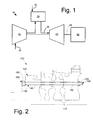
- Fig. 1 shows a schematic view of gas turbine engine 10 as may be used herein.
- the gas turbine engine 10 may include a compressor 15.
- the compressor 15 compresses an incoming flow of air 20.
- the compressor 15 delivers the compressed flow of air 20 to a combustor 25.
- the combustor 25 mixes the compressed flow of air 20 with a compressed flow of fuel 30 and ignites the mixture to create a flow of combustion gases 35.
- the gas turbine engine 10 may include any number of combustors 25.
- the flow of combustion gases 35 is in turn delivered to a turbine 40.
- the flow of combustion gases 35 drives the turbine 40 so as to produce mechanical work.
- the mechanical work produced in the turbine 40 drives the compressor 15 via a shaft 45 and an external load 50 such as an electrical generator and the like.
- the gas turbine engine 10 may use natural gas, various types of syngas, and/or other types of fuels.
- the gas turbine engine 10 may be any one of a number of different gas turbine engines offered by General Electric Company of Schenectady, New York, including, but not limited to, those such as a 7 or a 9 series heavy duty gas turbine engine and the like.
- the gas turbine engine 10 may have different configurations and may use other types of components.
- Other types of gas turbine engines also may be used herein.
- Multiple gas turbine engines, other types of turbines, and other types of power generation equipment also may be used herein together.
- Fig. 2 shows a portion of a rotary machine, in this case a compressor 100.
- the compressor 100 may be similar to the compressor 15 described above.
- the compressor 100 includes a number of wheels 110.
- the wheels 110 may be arranged in a stack 120.
- the wheels 110 and the stack 120 may be maintained in an axial configuration by a number of tie bolt assemblies 130.
- the tie bolt assemblies 130 extend axially along the length of the compressor stack 120 or a number of tie bolt assemblies 130 may be used for a number of stages therein.
- Each tie bolt assembly 130 includes a tie bolt 140.
- the tie bolt 140 may be an elongated stud with an aft end 150 and a forward end 160.
- Each tie bolt 140 may have a number of bolt threads 170 thereon.
- the bolt threads 170 may extend along the length of the tie bolt 140 or just about the aft end 150 and/or the forward end 160.
- the tie bolt 140 extends through a bore 180 in each wheel 110 of the stack 120
- each tie bolt 140 may be secured via an aft nut assembly 190.
- the aft nut assembly 190 may include a conventional twelve point nut that is forcibly abutted by a jam nut with a crimp. Many other types of aft nut assemblies 190 may be used herein. Other components and other configurations may be used herein.
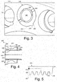
- Figs. 3-5 show a self locking nut and bolt assembly 200 as may be described herein.
- the self locking nut and bolt assembly 200 may secure the tie bolt 140 about the forward end 160 thereof within the bore 180 of the wheel 110 at the front of the stack 120.
- Multiple self locking nut and bolt assemblies 200 may be used herein together.
- the self locking nut and bolt assembly 200 includes a locking nut 210.
- the locking nut 210 and the components thereof are sized to fit securely within the bore 180 of the wheel 110.
- the locking nut 210 may include an interior bore 220 with nut threads 230 therein.
- the nut threads 230 mate with the bolt threads 170 of the tie bolt 140.
- the locking nut 210 also may include an aft flange 240, a reduced diameter center portion 250, and a forward flange 260.
- the forward flange 260 may include one or more tabs 270 extending radially outward.
- the tab 270 may be sized so as to mate with a cut out or notch 280 within the wheel 110 about the bore 180. Any number of tabs 270 and notches 280 may be used herein. The engagement of the tab 270 and the notch 280 prevents rotation of the locking nut 210.
- the locking nut 210 may be made out of a super alloy such as an nickel-chromium based super alloy including an Inconel material and similar types of materials. Other components and other configurations may be used herein.
- the locking nut 210 includes a cutout 290 about the internal bore 220 adjacent to the forward flange 260.
- the self locking nut and bolt assembly 200 thus includes a locking washer 300 positioned within the cutout 290.
- the locking washer 300 may include an internal washer bore 310 with a number of washer threads 320 positioned thereon.
- the washer threads 320 are sized to engage with the bolt threads 170 of the tie bolt 140.
- the locking washer 300 may be constructed from a fairly malleable material to aid the staking process as will be described in more detail below. Other components and other configurations may be used herein.
- the forward end 160 of the tie bolt 140 may be secured to the locking nut 210.
- the locking nut 210 is locked in place about the bore 180 of the wheel 110 via the tab 270 and notch 280.
- the locking washer 300 may be tightened thereon. Tightening the locking washer 300 against the locking nut 210 stretches the bolt 140 and generates a normal force on the locking washer 300 so as to create a compression force to prevent relative rotation.
- the locking washer 300 then may be staked into place.
- the forward flange 260 of the locking nut 210 may have one or more staking slots 330 formed therein so as to accommodate a staking tool without damage to the other components. Staking the locking washer 300 into place ensures that it cannot rotate about the end of the tie bolt 140. Because the threads 170 of the tie bolt 140 are pulled in opposite directions, neither the locking nut 210 nor the locking washer 300 can turn relative to the other such that the tie bolt 140 is locked and unable to rotate. The self locking nut and bolt assembly 200 thus prevents rotation of the tie bolt 140. The staking of the locking washer 300 into the locking nut 210 ensures that the compression load remains constant through out the operation of the gas turbine.
- the self locking nut and bolt assembly 200 thus fully locks the tie bolt 140, the locking nut 210, and the locking washer 300 in a simple and compact design. Moreover, no staking damage to the locking nut 210, the tie bolt 140, or the wheel 110 should result given that only the locking washer 300 is staked. Because the locking washer 300 is not a critical clamping component, it can be made of a lower strength material than the nuts and bolts so as to make it less expensive to replace.
- the self locking nut and bolt assembly 200 may be inspected during routine maintenance so as to ensure proper bolting loads are maintained.
- the self locking nut and bolt assembly 200 may include a low profile design for relatively tight space constraints. Moreover, the self locking nut and bolt assembly 200 also may be relatively lightweight so as to reduce bending stresses in the threads and undercuts. The self locking nut and bolt assembly 200 also may be easy to assemble without requiring complex or single purpose tools.
Landscapes
- Engineering & Computer Science (AREA)
- General Engineering & Computer Science (AREA)
- Mechanical Engineering (AREA)
- Connection Of Plates (AREA)
- Structures Of Non-Positive Displacement Pumps (AREA)
Abstract
Description
- The present application relates generally to gas turbine engines and more particularly relates to a self locking nut and bolt assembly for use with a compressor rotor or other type of rotary machine.
- The rotors of rotary machines, such as turbines and compressors, generally include a number of axially stacked wheels. A number of circumferentially spaced blades are mounted in turn about the periphery of the wheels for rotation therewith. For example, compressor rotors generally include a series of individual compressor wheels stacked together with a set of tie bolts extending axially therethrough. The wheels mount the rotor blades thereon to form the compressor stages with a corresponding number of stator blades. The tie bolts typically are elongated studs that may be threaded at both ends. The tie bolts are enclosed by nuts to maintain the wheels in a stacked, assembled relationship relative to one another. A sufficient load is applied to the tie bolts to ensure that the rotor torque is carried through the stack by friction between the wheels.
- It will be appreciated that any loosening of the nuts on the tie bolts would reduce the tension on the bolts and, thus, lower the torque carrying capability of the rotor. Current rotor designs thus require that the rotation of the nut relative to the bolt be prevented by redundant methods. One such method relies on friction against the threads and the stack. A second method uses a jam nut against a primary nut to prevent rotation relative to the stud. A further method uses a crimped or oblong nut barrel to increase the torque required for removal.
- There thus a desire for an improved nut and bolt assembly for use with a compressor rotor and other types of rotary machines. Such an improved nut and bolt assembly preferably would be self locking, would prevent gross rotation of the bolt without adding unnecessary weight or requiring damage to expensive assembly components and the like, and would be readily accessible for inspection and disassembly.
- The present invention provides a self locking nut and bolt assembly for a stack of rotating wheels. The self locking nut and bolt assembly may include a tie bolt extending through the stack of rotating wheels, a locking nut positioned on a first end of the tie bolt, and a locking washer positioned on the one end of the tie bolt within the locking nut.
- The present invention further provides a method of preventing rotation of a tie bolt in a stack of rotating wheels. The method may include the steps of positioning a locking nut on a first end of the tie bolt, locking the locking nut in place within a bore of one of the rotating wheels, positioning a locking washer on the tie bolt and within the locking nut, and staking the locking washer in place to prevent rotation of the bolt.
- These and other features of the present application and the resultant patent will become apparent to one of ordinary skill in the art upon review of the following detailed description when taken in conjunction with the several drawings and the appended claims.
- Embodiments of the present invention will now be described, by way of example only, with reference to the accompanying drawings in which:
-
Fig. 1 is a schematic view of a gas turbine engine. -
Fig. 2 is a schematic view of a stacked wheel assembly for a rotary machine with a self locking nut and bolt assembly as may be described herein. -
Fig. 3 is a perspective view of the self locking nut and bolt assembly ofFig. 2 positioned in a forward wheel of a wheel stack. -
Fig. 4 is a side cross-sectional view of the self locking nut and bolt assembly ofFig. 2 . -
Fig. 5 is a side cross-sectional view of the respective threads of the bolt, the nut, and the locking washer of the self locking nut and bolt assembly ofFig. 2 . - Referring now to the drawings, in which like numerals refer to like elements throughout the several views,
Fig. 1 shows a schematic view of gas turbine engine 10 as may be used herein. The gas turbine engine 10 may include acompressor 15. Thecompressor 15 compresses an incoming flow ofair 20. Thecompressor 15 delivers the compressed flow ofair 20 to acombustor 25. Thecombustor 25 mixes the compressed flow ofair 20 with a compressed flow offuel 30 and ignites the mixture to create a flow ofcombustion gases 35. Although only asingle combustor 25 is shown, the gas turbine engine 10 may include any number ofcombustors 25. The flow ofcombustion gases 35 is in turn delivered to aturbine 40. The flow ofcombustion gases 35 drives theturbine 40 so as to produce mechanical work. The mechanical work produced in theturbine 40 drives thecompressor 15 via ashaft 45 and anexternal load 50 such as an electrical generator and the like. - The gas turbine engine 10 may use natural gas, various types of syngas, and/or other types of fuels. The gas turbine engine 10 may be any one of a number of different gas turbine engines offered by General Electric Company of Schenectady, New York, including, but not limited to, those such as a 7 or a 9 series heavy duty gas turbine engine and the like. The gas turbine engine 10 may have different configurations and may use other types of components. Other types of gas turbine engines also may be used herein. Multiple gas turbine engines, other types of turbines, and other types of power generation equipment also may be used herein together.
-
Fig. 2 shows a portion of a rotary machine, in this case acompressor 100. Thecompressor 100 may be similar to thecompressor 15 described above. As such, thecompressor 100 includes a number ofwheels 110. Thewheels 110 may be arranged in astack 120. Thewheels 110 and thestack 120 may be maintained in an axial configuration by a number oftie bolt assemblies 130. Thetie bolt assemblies 130 extend axially along the length of thecompressor stack 120 or a number oftie bolt assemblies 130 may be used for a number of stages therein. Eachtie bolt assembly 130 includes atie bolt 140. Thetie bolt 140 may be an elongated stud with anaft end 150 and aforward end 160. Eachtie bolt 140 may have a number ofbolt threads 170 thereon. Thebolt threads 170 may extend along the length of thetie bolt 140 or just about theaft end 150 and/or theforward end 160. Thetie bolt 140 extends through abore 180 in eachwheel 110 of thestack 120. - The
aft end 150 of eachtie bolt 140 may be secured via anaft nut assembly 190. In this example, theaft nut assembly 190 may include a conventional twelve point nut that is forcibly abutted by a jam nut with a crimp. Many other types ofaft nut assemblies 190 may be used herein. Other components and other configurations may be used herein. -
Figs. 3-5 show a self locking nut andbolt assembly 200 as may be described herein. The self locking nut andbolt assembly 200 may secure thetie bolt 140 about theforward end 160 thereof within thebore 180 of thewheel 110 at the front of thestack 120. Multiple self locking nut andbolt assemblies 200 may be used herein together. - The self locking nut and
bolt assembly 200 includes alocking nut 210. Thelocking nut 210 and the components thereof are sized to fit securely within thebore 180 of thewheel 110. The lockingnut 210 may include aninterior bore 220 withnut threads 230 therein. Thenut threads 230 mate with thebolt threads 170 of thetie bolt 140. The lockingnut 210 also may include anaft flange 240, a reduceddiameter center portion 250, and aforward flange 260. Theforward flange 260 may include one ormore tabs 270 extending radially outward. Thetab 270 may be sized so as to mate with a cut out or notch 280 within thewheel 110 about thebore 180. Any number oftabs 270 andnotches 280 may be used herein. The engagement of thetab 270 and thenotch 280 prevents rotation of the lockingnut 210. - Examples of the configuration and the use of the locking
nut 210 are shown in commonly ownedU.S. Patent No. 6,784,597 . The lockingnut 210 may be made out of a super alloy such as an nickel-chromium based super alloy including an Inconel material and similar types of materials. Other components and other configurations may be used herein. - In this example, the locking
nut 210 includes acutout 290 about theinternal bore 220 adjacent to theforward flange 260. The self locking nut andbolt assembly 200 thus includes a lockingwasher 300 positioned within thecutout 290. The lockingwasher 300 may include an internal washer bore 310 with a number ofwasher threads 320 positioned thereon. Thewasher threads 320 are sized to engage with thebolt threads 170 of thetie bolt 140. The lockingwasher 300 may be constructed from a fairly malleable material to aid the staking process as will be described in more detail below. Other components and other configurations may be used herein. - In use, the
forward end 160 of thetie bolt 140 may be secured to the lockingnut 210. The lockingnut 210 is locked in place about thebore 180 of thewheel 110 via thetab 270 and notch 280. Once thetie bolt 140 is tensioned to its full load, the lockingwasher 300 may be tightened thereon. Tightening the lockingwasher 300 against the lockingnut 210 stretches thebolt 140 and generates a normal force on the lockingwasher 300 so as to create a compression force to prevent relative rotation. - The locking
washer 300 then may be staked into place. Theforward flange 260 of the lockingnut 210 may have one ormore staking slots 330 formed therein so as to accommodate a staking tool without damage to the other components. Staking the lockingwasher 300 into place ensures that it cannot rotate about the end of thetie bolt 140. Because thethreads 170 of thetie bolt 140 are pulled in opposite directions, neither the lockingnut 210 nor the lockingwasher 300 can turn relative to the other such that thetie bolt 140 is locked and unable to rotate. The self locking nut andbolt assembly 200 thus prevents rotation of thetie bolt 140. The staking of the lockingwasher 300 into the lockingnut 210 ensures that the compression load remains constant through out the operation of the gas turbine. - The self locking nut and
bolt assembly 200 thus fully locks thetie bolt 140, the lockingnut 210, and the lockingwasher 300 in a simple and compact design. Moreover, no staking damage to the lockingnut 210, thetie bolt 140, or thewheel 110 should result given that only the lockingwasher 300 is staked. Because the lockingwasher 300 is not a critical clamping component, it can be made of a lower strength material than the nuts and bolts so as to make it less expensive to replace. The self locking nut andbolt assembly 200 may be inspected during routine maintenance so as to ensure proper bolting loads are maintained. The self locking nut andbolt assembly 200 may include a low profile design for relatively tight space constraints. Moreover, the self locking nut andbolt assembly 200 also may be relatively lightweight so as to reduce bending stresses in the threads and undercuts. The self locking nut andbolt assembly 200 also may be easy to assemble without requiring complex or single purpose tools. - It should be apparent that the foregoing relates only to certain embodiments of the present application and the resultant patent. Numerous changes and modifications may be made herein by one of ordinary skill in the art without departing from the general spirit and scope of the invention as defined by the following claims and the equivalents thereof.
- Various aspects and embodiments of the present invention are defined by the following numbered clauses:
- 1. A self locking nut and bolt assembly for a stack of rotating compressor wheels, comprising:
- a tie bolt extending through the stack of rotating wheels;
- the tie bolt comprising bolt threads thereon;
- a locking nut positioned on a front end of the tie bolt;
- the locking nut comprising nut threads sized to accommodate the bolt threads;
- a locking washer positioned on the front end of the tie bolt within the locking nut; and
- the locking washer comprising washer threads sized to accommodate the bolt threads.
- 2. The self locking nut and bolt assembly of clause 1, wherein the locking nut and the locking washer share the bolt threads and are forcibly abutted.
- 3. The self locking nut and bolt assembly of clause 1 or 2, wherein the locking nut comprises a forward flange.
- 4. The self locking nut and bolt assembly of clause 3, wherein the forward flange comprises a tab therein and wherein a forward wheel of the stack comprises a notch sized to accommodate the tab.
- 5. The self locking nut and bolt assembly of any of clauses 1 to 4, wherein the locking nut comprises one or more stacking slots thereon.
Claims (15)
- A self locking nut and bolt assembly (200) for a stack (120) of rotating wheels (110), comprising:a tie bolt (140) extending through the stack (120) of rotating wheels (110);a locking nut (210) positioned on a first end (160) of the tie bolt (140); anda locking washer (300) positioned on the one end (160) of the tie bolt (140) within the locking nut (210).
- The self locking nut and bolt assembly (200) of claim 1, wherein the tie bolt (140) comprises bolt threads (170), the locking nut (210) comprises nut threads (230) sized to accommodate the bolt threads (170), and the locking washer (300) comprises washer threads (320) sized to accommodate the bolts threads (170).
- The self locking nut and bolt assembly (200) of claim 2, wherein the locking nut (210) and the locking washer (300) share the bolt threads (170) and are forcibly abutted.
- The self locking nut and bolt assembly (200) of any of claims 1 to 3, wherein the first end (160) of the tie bolt comprises a forward end (160).
- The self locking nut and bolt assembly (200) of any of claims 1 to 4, wherein the locking nut (210) comprises a forward flange (260).
- The self locking nut and bolt assembly (200) of claim 5, wherein the forward flange (260) comprises a tab (270) therein and wherein a forward wheel (110) of the stack (120) comprises a notch (280) sized to accommodate the tab (270).
- The self locking nut and bolt assembly (200) of any of claims 1 to 6, further comprising an aft nut assembly (190) positioned on a second end (150) of the tie bolt (140).
- The self locking nut and bolt assembly (200) of any preceding claim, wherein the locking nut (210) comprises one or more staking slots (330) thereon.
- The self locking nut and bolt assembly (200) of any preceding claim, wherein the locking nut (210) comprises a bore (220) surrounding the tie bolt (140).
- The self locking nut and bolt assembly (200) of any preceding claim, wherein the locking nut (210) comprises a cut out (290) sized to accommodate the locking washer (300).
- The self locking nut and bolt assembly (200) of any preceding claim wherein the locking washer (300) comprises a washer bore (310) surrounding the tie bolt (140).
- The self locking nut and bolt assembly (200) of any preceding claim, wherein the locking nut (210) comprises a super alloy material.
- The self locking nut and bolt assembly (200) of any preceding claim, wherein the locking washer (300) comprises a malleable material for staking.
- The self locking nut and bolt assembly (200) of any preceding claim, wherein each of the wheels (110) comprises a wheel bore (180) therethrough and wherein the locking nut (210) is sized to accommodate the wheel bore (180).
- A method of preventing rotation of a tie bolt (140) in a stack of rotating wheels (110), comprising:positioning a locking nut (210) on a first end (160) of the tie bolt (140);locking the locking nut (210) in place within a bore (180) of one of the rotating wheels (110);positioning a locking washer (300) on the tie bolt (140) and within the locking nut (210); andstaking the locking washer (300) in place.
Applications Claiming Priority (1)
| Application Number | Priority Date | Filing Date | Title |
|---|---|---|---|
| US13/195,875 US9322275B2 (en) | 2011-08-02 | 2011-08-02 | Self locking nut and bolt assembly |
Publications (3)
| Publication Number | Publication Date |
|---|---|
| EP2554790A2 true EP2554790A2 (en) | 2013-02-06 |
| EP2554790A3 EP2554790A3 (en) | 2017-06-07 |
| EP2554790B1 EP2554790B1 (en) | 2019-12-18 |
Family
ID=46679135
Family Applications (1)
| Application Number | Title | Priority Date | Filing Date |
|---|---|---|---|
| EP12177967.2A Active EP2554790B1 (en) | 2011-08-02 | 2012-07-26 | Self Locking Nut and Bolt Assembly |
Country Status (3)
| Country | Link |
|---|---|
| US (1) | US9322275B2 (en) |
| EP (1) | EP2554790B1 (en) |
| CN (1) | CN102913530B (en) |
Families Citing this family (3)
| Publication number | Priority date | Publication date | Assignee | Title |
|---|---|---|---|---|
| GB201309952D0 (en) * | 2013-06-04 | 2013-07-17 | Siemens Ag | Shaft arrangement |
| US9689261B2 (en) | 2013-11-11 | 2017-06-27 | General Electric Company | Stacked wheel assembly for a rotor of a rotary machine |
| WO2022049064A1 (en) * | 2020-09-03 | 2022-03-10 | Siemens Gas And Power Gmbh & Co. Kg | Rotor assembly for a gas turbine |
Citations (1)
| Publication number | Priority date | Publication date | Assignee | Title |
|---|---|---|---|---|
| US6784597B1 (en) | 2003-04-15 | 2004-08-31 | General Electric Company | Self-locking nut for stud shaft and stacked wheel assembly for the rotor of a rotary machine |
Family Cites Families (27)
| Publication number | Priority date | Publication date | Assignee | Title |
|---|---|---|---|---|
| US578194A (en) * | 1897-03-02 | Nut-lock | ||
| US632422A (en) * | 1899-02-11 | 1899-09-05 | John Hunnewell | Lock-nut. |
| US783572A (en) * | 1904-11-29 | 1905-02-28 | Columbia Nut And Bolt Company | Nut-lock. |
| US972968A (en) * | 1910-03-03 | 1910-10-18 | Joseph B Wismer | Nut-lock. |
| US1196565A (en) * | 1916-01-18 | 1916-08-29 | Alexander Mcdonald | Lock-nut. |
| US1235205A (en) * | 1916-10-30 | 1917-07-31 | James S Kierstead | Nut-lock. |
| US1400154A (en) * | 1920-02-19 | 1921-12-13 | Edward A Green | Nut-lock |
| US1352918A (en) * | 1920-02-21 | 1920-09-14 | William L Rohbock | Fastening device |
| US1470528A (en) * | 1921-06-11 | 1923-10-09 | Flentjen Auguste | Lock screw |
| US1717789A (en) * | 1927-02-15 | 1929-06-18 | Thomas H Brown | Lock nut |
| US1779896A (en) * | 1929-05-31 | 1930-10-28 | Winter Alois | Screw composed of several parts |
| US4035901A (en) * | 1976-07-22 | 1977-07-19 | Robertshaw Controls Company | Apparatus for joining two abutting metal members together and method of making such apparatus |
| US4260005A (en) * | 1977-11-09 | 1981-04-07 | Vsi Corporation | Self-locking fastener, fastener system, and process |
| JPS602336Y2 (en) * | 1980-11-26 | 1985-01-23 | 株式会社 冨士精密製作所 | Loosening nut |
| US5004389A (en) | 1988-06-13 | 1991-04-02 | Industrial Nut Corp. | Externally threaded self-locking nut |
| US5090854A (en) | 1991-03-06 | 1992-02-25 | Artifex Ltd. | Self locking nut |
| US5226788A (en) | 1991-12-23 | 1993-07-13 | General Electric Company | Turbine heat shield and bolt retainer assembly |
| US5796202A (en) | 1997-02-20 | 1998-08-18 | General Electric Co. | Tie bolt and stacked wheel assembly for the rotor of a rotary machine |
| US5860779A (en) * | 1997-11-26 | 1999-01-19 | Mcdonnell Douglas Corporation | Locking nut |
| US6220804B1 (en) | 1999-03-24 | 2001-04-24 | R B & W Corporation | Self-piercing clinch nut |
| US7207760B2 (en) * | 2001-12-06 | 2007-04-24 | Junkers John K | Washer and fastener provided with a washer |
| DE10163282B4 (en) * | 2001-12-21 | 2005-06-09 | Visteon Global Technologies, Inc., Dearborn | Rack and pinion, in particular rack and pinion steering gear and method for its preparation |
| DE102005012048A1 (en) * | 2005-03-08 | 2006-09-14 | Dr.Ing.H.C. F. Porsche Ag | Turbine housing of an exhaust gas turbocharger with adjustable turbine geometry |
| US20070201965A1 (en) * | 2006-02-28 | 2007-08-30 | Barry Littlewood | Threaded fastening systems |
| US7437976B1 (en) * | 2006-09-05 | 2008-10-21 | Harold Goldbaum | Positive auto-blocking nut ensemble and torqueing tool |
| CN100425846C (en) * | 2006-12-22 | 2008-10-15 | 魏民 | Accentric self locking nut |
| CN102094886B (en) * | 2011-01-20 | 2013-01-23 | 宁波信泰机械有限公司 | Bolted connection structure and lock washer and luggage rack thereof |
-
2011
- 2011-08-02 US US13/195,875 patent/US9322275B2/en active Active
-
2012
- 2012-07-26 EP EP12177967.2A patent/EP2554790B1/en active Active
- 2012-08-02 CN CN201210272337.9A patent/CN102913530B/en active Active
Patent Citations (1)
| Publication number | Priority date | Publication date | Assignee | Title |
|---|---|---|---|---|
| US6784597B1 (en) | 2003-04-15 | 2004-08-31 | General Electric Company | Self-locking nut for stud shaft and stacked wheel assembly for the rotor of a rotary machine |
Also Published As
| Publication number | Publication date |
|---|---|
| CN102913530A (en) | 2013-02-06 |
| CN102913530B (en) | 2017-03-01 |
| US9322275B2 (en) | 2016-04-26 |
| EP2554790B1 (en) | 2019-12-18 |
| US20130034402A1 (en) | 2013-02-07 |
| EP2554790A3 (en) | 2017-06-07 |
Similar Documents
| Publication | Publication Date | Title |
|---|---|---|
| CN105308265B (en) | Including be arranged on be shell between axis and rotor combustion gas turbine system shaft device | |
| US9217334B2 (en) | Turbine cover plate assembly | |
| US20090034896A1 (en) | Bearing retainer | |
| EP3343002B1 (en) | Casing for gas turbine and gas turbine | |
| US10001029B2 (en) | Bearing locking assemblies and methods of assembling the same | |
| EP2554790B1 (en) | Self Locking Nut and Bolt Assembly | |
| US8545184B2 (en) | Locking spacer assembly | |
| US20180187711A1 (en) | Locking nut and bolt assemblies for reducing windage in the vicinity of a high pressure flow region of a gas turbine engine | |
| US9163514B2 (en) | System and method for coupling rotor components | |
| JP4778892B2 (en) | Self-locking nut and stack wheel assembly for rotor shaft stud shaft | |
| EP2594751A2 (en) | Stud Retention | |
| US10274016B2 (en) | Turbine engine bearing assembly and method for assembling the same | |
| JP7570819B2 (en) | Damper and spring lock mechanism for generator field | |
| US10562159B2 (en) | Bolt tightening system | |
| US9109456B2 (en) | System for coupling a segment to a rotor of a turbomachine | |
| US9689261B2 (en) | Stacked wheel assembly for a rotor of a rotary machine | |
| US10267328B2 (en) | Rotor structure for rotating machinery and method of assembly thereof | |
| EP4671502A2 (en) | Mid-body generator for a turbine engine |
Legal Events
| Date | Code | Title | Description |
|---|---|---|---|
| PUAI | Public reference made under article 153(3) epc to a published international application that has entered the european phase |
Free format text: ORIGINAL CODE: 0009012 |
|
| AK | Designated contracting states |
Kind code of ref document: A2 Designated state(s): AL AT BE BG CH CY CZ DE DK EE ES FI FR GB GR HR HU IE IS IT LI LT LU LV MC MK MT NL NO PL PT RO RS SE SI SK SM TR |
|
| AX | Request for extension of the european patent |
Extension state: BA ME |
|
| PUAL | Search report despatched |
Free format text: ORIGINAL CODE: 0009013 |
|
| AK | Designated contracting states |
Kind code of ref document: A3 Designated state(s): AL AT BE BG CH CY CZ DE DK EE ES FI FR GB GR HR HU IE IS IT LI LT LU LV MC MK MT NL NO PL PT RO RS SE SI SK SM TR |
|
| AX | Request for extension of the european patent |
Extension state: BA ME |
|
| RIC1 | Information provided on ipc code assigned before grant |
Ipc: F16B 39/00 20060101ALI20170503BHEP Ipc: F16B 39/12 20060101ALI20170503BHEP Ipc: F16B 39/02 20060101ALI20170503BHEP Ipc: F01D 5/06 20060101AFI20170503BHEP |
|
| PUAL | Search report despatched |
Free format text: ORIGINAL CODE: 0009013 |
|
| STAA | Information on the status of an ep patent application or granted ep patent |
Free format text: STATUS: REQUEST FOR EXAMINATION WAS MADE |
|
| 17P | Request for examination filed |
Effective date: 20171207 |
|
| RBV | Designated contracting states (corrected) |
Designated state(s): AL AT BE BG CH CY CZ DE DK EE ES FI FR GB GR HR HU IE IS IT LI LT LU LV MC MK MT NL NO PL PT RO RS SE SI SK SM TR |
|
| GRAP | Despatch of communication of intention to grant a patent |
Free format text: ORIGINAL CODE: EPIDOSNIGR1 |
|
| STAA | Information on the status of an ep patent application or granted ep patent |
Free format text: STATUS: GRANT OF PATENT IS INTENDED |
|
| INTG | Intention to grant announced |
Effective date: 20190704 |
|
| GRAS | Grant fee paid |
Free format text: ORIGINAL CODE: EPIDOSNIGR3 |
|
| GRAA | (expected) grant |
Free format text: ORIGINAL CODE: 0009210 |
|
| STAA | Information on the status of an ep patent application or granted ep patent |
Free format text: STATUS: THE PATENT HAS BEEN GRANTED |
|
| AK | Designated contracting states |
Kind code of ref document: B1 Designated state(s): AL AT BE BG CH CY CZ DE DK EE ES FI FR GB GR HR HU IE IS IT LI LT LU LV MC MK MT NL NO PL PT RO RS SE SI SK SM TR |
|
| REG | Reference to a national code |
Ref country code: GB Ref legal event code: FG4D |
|
| REG | Reference to a national code |
Ref country code: CH Ref legal event code: EP |
|
| REG | Reference to a national code |
Ref country code: DE Ref legal event code: R096 Ref document number: 602012066516 Country of ref document: DE |
|
| REG | Reference to a national code |
Ref country code: IE Ref legal event code: FG4D |
|
| REG | Reference to a national code |
Ref country code: AT Ref legal event code: REF Ref document number: 1214802 Country of ref document: AT Kind code of ref document: T Effective date: 20200115 |
|
| REG | Reference to a national code |
Ref country code: NL Ref legal event code: MP Effective date: 20191218 |
|
| PG25 | Lapsed in a contracting state [announced via postgrant information from national office to epo] |
Ref country code: FI Free format text: LAPSE BECAUSE OF FAILURE TO SUBMIT A TRANSLATION OF THE DESCRIPTION OR TO PAY THE FEE WITHIN THE PRESCRIBED TIME-LIMIT Effective date: 20191218 Ref country code: SE Free format text: LAPSE BECAUSE OF FAILURE TO SUBMIT A TRANSLATION OF THE DESCRIPTION OR TO PAY THE FEE WITHIN THE PRESCRIBED TIME-LIMIT Effective date: 20191218 Ref country code: LT Free format text: LAPSE BECAUSE OF FAILURE TO SUBMIT A TRANSLATION OF THE DESCRIPTION OR TO PAY THE FEE WITHIN THE PRESCRIBED TIME-LIMIT Effective date: 20191218 Ref country code: BG Free format text: LAPSE BECAUSE OF FAILURE TO SUBMIT A TRANSLATION OF THE DESCRIPTION OR TO PAY THE FEE WITHIN THE PRESCRIBED TIME-LIMIT Effective date: 20200318 Ref country code: GR Free format text: LAPSE BECAUSE OF FAILURE TO SUBMIT A TRANSLATION OF THE DESCRIPTION OR TO PAY THE FEE WITHIN THE PRESCRIBED TIME-LIMIT Effective date: 20200319 Ref country code: LV Free format text: LAPSE BECAUSE OF FAILURE TO SUBMIT A TRANSLATION OF THE DESCRIPTION OR TO PAY THE FEE WITHIN THE PRESCRIBED TIME-LIMIT Effective date: 20191218 Ref country code: NO Free format text: LAPSE BECAUSE OF FAILURE TO SUBMIT A TRANSLATION OF THE DESCRIPTION OR TO PAY THE FEE WITHIN THE PRESCRIBED TIME-LIMIT Effective date: 20200318 |
|
| REG | Reference to a national code |
Ref country code: LT Ref legal event code: MG4D |
|
| PG25 | Lapsed in a contracting state [announced via postgrant information from national office to epo] |
Ref country code: RS Free format text: LAPSE BECAUSE OF FAILURE TO SUBMIT A TRANSLATION OF THE DESCRIPTION OR TO PAY THE FEE WITHIN THE PRESCRIBED TIME-LIMIT Effective date: 20191218 Ref country code: HR Free format text: LAPSE BECAUSE OF FAILURE TO SUBMIT A TRANSLATION OF THE DESCRIPTION OR TO PAY THE FEE WITHIN THE PRESCRIBED TIME-LIMIT Effective date: 20191218 |
|
| PG25 | Lapsed in a contracting state [announced via postgrant information from national office to epo] |
Ref country code: AL Free format text: LAPSE BECAUSE OF FAILURE TO SUBMIT A TRANSLATION OF THE DESCRIPTION OR TO PAY THE FEE WITHIN THE PRESCRIBED TIME-LIMIT Effective date: 20191218 |
|
| PG25 | Lapsed in a contracting state [announced via postgrant information from national office to epo] |
Ref country code: EE Free format text: LAPSE BECAUSE OF FAILURE TO SUBMIT A TRANSLATION OF THE DESCRIPTION OR TO PAY THE FEE WITHIN THE PRESCRIBED TIME-LIMIT Effective date: 20191218 Ref country code: NL Free format text: LAPSE BECAUSE OF FAILURE TO SUBMIT A TRANSLATION OF THE DESCRIPTION OR TO PAY THE FEE WITHIN THE PRESCRIBED TIME-LIMIT Effective date: 20191218 Ref country code: PT Free format text: LAPSE BECAUSE OF FAILURE TO SUBMIT A TRANSLATION OF THE DESCRIPTION OR TO PAY THE FEE WITHIN THE PRESCRIBED TIME-LIMIT Effective date: 20200513 Ref country code: CZ Free format text: LAPSE BECAUSE OF FAILURE TO SUBMIT A TRANSLATION OF THE DESCRIPTION OR TO PAY THE FEE WITHIN THE PRESCRIBED TIME-LIMIT Effective date: 20191218 Ref country code: RO Free format text: LAPSE BECAUSE OF FAILURE TO SUBMIT A TRANSLATION OF THE DESCRIPTION OR TO PAY THE FEE WITHIN THE PRESCRIBED TIME-LIMIT Effective date: 20191218 |
|
| PG25 | Lapsed in a contracting state [announced via postgrant information from national office to epo] |
Ref country code: IS Free format text: LAPSE BECAUSE OF FAILURE TO SUBMIT A TRANSLATION OF THE DESCRIPTION OR TO PAY THE FEE WITHIN THE PRESCRIBED TIME-LIMIT Effective date: 20200418 Ref country code: SK Free format text: LAPSE BECAUSE OF FAILURE TO SUBMIT A TRANSLATION OF THE DESCRIPTION OR TO PAY THE FEE WITHIN THE PRESCRIBED TIME-LIMIT Effective date: 20191218 Ref country code: SM Free format text: LAPSE BECAUSE OF FAILURE TO SUBMIT A TRANSLATION OF THE DESCRIPTION OR TO PAY THE FEE WITHIN THE PRESCRIBED TIME-LIMIT Effective date: 20191218 |
|
| REG | Reference to a national code |
Ref country code: DE Ref legal event code: R097 Ref document number: 602012066516 Country of ref document: DE |
|
| REG | Reference to a national code |
Ref country code: AT Ref legal event code: MK05 Ref document number: 1214802 Country of ref document: AT Kind code of ref document: T Effective date: 20191218 |
|
| PLBE | No opposition filed within time limit |
Free format text: ORIGINAL CODE: 0009261 |
|
| STAA | Information on the status of an ep patent application or granted ep patent |
Free format text: STATUS: NO OPPOSITION FILED WITHIN TIME LIMIT |
|
| PG25 | Lapsed in a contracting state [announced via postgrant information from national office to epo] |
Ref country code: ES Free format text: LAPSE BECAUSE OF FAILURE TO SUBMIT A TRANSLATION OF THE DESCRIPTION OR TO PAY THE FEE WITHIN THE PRESCRIBED TIME-LIMIT Effective date: 20191218 Ref country code: DK Free format text: LAPSE BECAUSE OF FAILURE TO SUBMIT A TRANSLATION OF THE DESCRIPTION OR TO PAY THE FEE WITHIN THE PRESCRIBED TIME-LIMIT Effective date: 20191218 |
|
| 26N | No opposition filed |
Effective date: 20200921 |
|
| PG25 | Lapsed in a contracting state [announced via postgrant information from national office to epo] |
Ref country code: SI Free format text: LAPSE BECAUSE OF FAILURE TO SUBMIT A TRANSLATION OF THE DESCRIPTION OR TO PAY THE FEE WITHIN THE PRESCRIBED TIME-LIMIT Effective date: 20191218 Ref country code: AT Free format text: LAPSE BECAUSE OF FAILURE TO SUBMIT A TRANSLATION OF THE DESCRIPTION OR TO PAY THE FEE WITHIN THE PRESCRIBED TIME-LIMIT Effective date: 20191218 |
|
| PG25 | Lapsed in a contracting state [announced via postgrant information from national office to epo] |
Ref country code: IT Free format text: LAPSE BECAUSE OF FAILURE TO SUBMIT A TRANSLATION OF THE DESCRIPTION OR TO PAY THE FEE WITHIN THE PRESCRIBED TIME-LIMIT Effective date: 20191218 |
|
| PG25 | Lapsed in a contracting state [announced via postgrant information from national office to epo] |
Ref country code: MC Free format text: LAPSE BECAUSE OF FAILURE TO SUBMIT A TRANSLATION OF THE DESCRIPTION OR TO PAY THE FEE WITHIN THE PRESCRIBED TIME-LIMIT Effective date: 20191218 Ref country code: PL Free format text: LAPSE BECAUSE OF FAILURE TO SUBMIT A TRANSLATION OF THE DESCRIPTION OR TO PAY THE FEE WITHIN THE PRESCRIBED TIME-LIMIT Effective date: 20191218 |
|
| REG | Reference to a national code |
Ref country code: CH Ref legal event code: PL |
|
| REG | Reference to a national code |
Ref country code: BE Ref legal event code: MM Effective date: 20200731 |
|
| PG25 | Lapsed in a contracting state [announced via postgrant information from national office to epo] |
Ref country code: FR Free format text: LAPSE BECAUSE OF NON-PAYMENT OF DUE FEES Effective date: 20200731 Ref country code: LU Free format text: LAPSE BECAUSE OF NON-PAYMENT OF DUE FEES Effective date: 20200726 Ref country code: LI Free format text: LAPSE BECAUSE OF NON-PAYMENT OF DUE FEES Effective date: 20200731 Ref country code: CH Free format text: LAPSE BECAUSE OF NON-PAYMENT OF DUE FEES Effective date: 20200731 |
|
| PG25 | Lapsed in a contracting state [announced via postgrant information from national office to epo] |
Ref country code: BE Free format text: LAPSE BECAUSE OF NON-PAYMENT OF DUE FEES Effective date: 20200731 |
|
| PG25 | Lapsed in a contracting state [announced via postgrant information from national office to epo] |
Ref country code: IE Free format text: LAPSE BECAUSE OF NON-PAYMENT OF DUE FEES Effective date: 20200726 |
|
| PG25 | Lapsed in a contracting state [announced via postgrant information from national office to epo] |
Ref country code: TR Free format text: LAPSE BECAUSE OF FAILURE TO SUBMIT A TRANSLATION OF THE DESCRIPTION OR TO PAY THE FEE WITHIN THE PRESCRIBED TIME-LIMIT Effective date: 20191218 Ref country code: MT Free format text: LAPSE BECAUSE OF FAILURE TO SUBMIT A TRANSLATION OF THE DESCRIPTION OR TO PAY THE FEE WITHIN THE PRESCRIBED TIME-LIMIT Effective date: 20191218 Ref country code: CY Free format text: LAPSE BECAUSE OF FAILURE TO SUBMIT A TRANSLATION OF THE DESCRIPTION OR TO PAY THE FEE WITHIN THE PRESCRIBED TIME-LIMIT Effective date: 20191218 |
|
| PG25 | Lapsed in a contracting state [announced via postgrant information from national office to epo] |
Ref country code: MK Free format text: LAPSE BECAUSE OF FAILURE TO SUBMIT A TRANSLATION OF THE DESCRIPTION OR TO PAY THE FEE WITHIN THE PRESCRIBED TIME-LIMIT Effective date: 20191218 |
|
| REG | Reference to a national code |
Ref country code: DE Ref legal event code: R082 Ref document number: 602012066516 Country of ref document: DE Ref country code: DE Ref legal event code: R081 Ref document number: 602012066516 Country of ref document: DE Owner name: GENERAL ELECTRIC TECHNOLOGY GMBH, CH Free format text: FORMER OWNER: GENERAL ELECTRIC COMPANY, SCHENECTADY, NY, US |
|
| REG | Reference to a national code |
Ref country code: GB Ref legal event code: 732E Free format text: REGISTERED BETWEEN 20240222 AND 20240228 |
|
| PGFP | Annual fee paid to national office [announced via postgrant information from national office to epo] |
Ref country code: GB Payment date: 20250619 Year of fee payment: 14 |
|
| PGFP | Annual fee paid to national office [announced via postgrant information from national office to epo] |
Ref country code: DE Payment date: 20250620 Year of fee payment: 14 |