EP2554787A2 - Gas lift valve having edge-welded bellows and captive sliding seal - Google Patents
Gas lift valve having edge-welded bellows and captive sliding seal Download PDFInfo
- Publication number
- EP2554787A2 EP2554787A2 EP20120179046 EP12179046A EP2554787A2 EP 2554787 A2 EP2554787 A2 EP 2554787A2 EP 20120179046 EP20120179046 EP 20120179046 EP 12179046 A EP12179046 A EP 12179046A EP 2554787 A2 EP2554787 A2 EP 2554787A2
- Authority
- EP
- European Patent Office
- Prior art keywords
- bellows
- piston
- edge
- seal
- disposed
- Prior art date
- Legal status (The legal status is an assumption and is not a legal conclusion. Google has not performed a legal analysis and makes no representation as to the accuracy of the status listed.)
- Granted
Links
- 238000007789 sealing Methods 0.000 claims description 61
- 239000012530 fluid Substances 0.000 claims description 41
- 238000004891 communication Methods 0.000 claims description 23
- 239000007789 gas Substances 0.000 description 124
- 238000002347 injection Methods 0.000 description 34
- 239000007924 injection Substances 0.000 description 34
- 238000004519 manufacturing process Methods 0.000 description 32
- 239000003921 oil Substances 0.000 description 12
- 239000007787 solid Substances 0.000 description 10
- IJGRMHOSHXDMSA-UHFFFAOYSA-N Atomic nitrogen Chemical compound N#N IJGRMHOSHXDMSA-UHFFFAOYSA-N 0.000 description 8
- 230000009977 dual effect Effects 0.000 description 7
- 239000002184 metal Substances 0.000 description 7
- 229910052751 metal Inorganic materials 0.000 description 7
- 229920002545 silicone oil Polymers 0.000 description 5
- 230000015572 biosynthetic process Effects 0.000 description 4
- 230000006835 compression Effects 0.000 description 4
- 238000007906 compression Methods 0.000 description 4
- 230000007246 mechanism Effects 0.000 description 4
- 229910052757 nitrogen Inorganic materials 0.000 description 4
- RYGMFSIKBFXOCR-UHFFFAOYSA-N Copper Chemical compound [Cu] RYGMFSIKBFXOCR-UHFFFAOYSA-N 0.000 description 3
- 229910045601 alloy Inorganic materials 0.000 description 3
- 239000000956 alloy Substances 0.000 description 3
- 230000008901 benefit Effects 0.000 description 3
- 229910052802 copper Inorganic materials 0.000 description 3
- 239000010949 copper Substances 0.000 description 3
- 230000000694 effects Effects 0.000 description 3
- 229910001026 inconel Inorganic materials 0.000 description 3
- 230000014759 maintenance of location Effects 0.000 description 3
- 239000000463 material Substances 0.000 description 3
- 238000000034 method Methods 0.000 description 3
- 229920001343 polytetrafluoroethylene Polymers 0.000 description 3
- 239000004810 polytetrafluoroethylene Substances 0.000 description 3
- 239000004215 Carbon black (E152) Substances 0.000 description 2
- 229910000792 Monel Inorganic materials 0.000 description 2
- 229920006362 Teflon® Polymers 0.000 description 2
- 230000006837 decompression Effects 0.000 description 2
- 239000002360 explosive Substances 0.000 description 2
- 229930195733 hydrocarbon Natural products 0.000 description 2
- 150000002430 hydrocarbons Chemical class 0.000 description 2
- 230000013011 mating Effects 0.000 description 2
- UONOETXJSWQNOL-UHFFFAOYSA-N tungsten carbide Chemical compound [W+]#[C-] UONOETXJSWQNOL-UHFFFAOYSA-N 0.000 description 2
- XLYOFNOQVPJJNP-UHFFFAOYSA-N water Substances O XLYOFNOQVPJJNP-UHFFFAOYSA-N 0.000 description 2
- 241000270295 Serpentes Species 0.000 description 1
- XUIMIQQOPSSXEZ-UHFFFAOYSA-N Silicon Chemical compound [Si] XUIMIQQOPSSXEZ-UHFFFAOYSA-N 0.000 description 1
- 239000004809 Teflon Substances 0.000 description 1
- 230000004075 alteration Effects 0.000 description 1
- 238000004873 anchoring Methods 0.000 description 1
- 239000004568 cement Substances 0.000 description 1
- 230000000295 complement effect Effects 0.000 description 1
- 238000010276 construction Methods 0.000 description 1
- 229920001971 elastomer Polymers 0.000 description 1
- 239000000806 elastomer Substances 0.000 description 1
- 239000013536 elastomeric material Substances 0.000 description 1
- 238000010894 electron beam technology Methods 0.000 description 1
- 230000003628 erosive effect Effects 0.000 description 1
- 238000009434 installation Methods 0.000 description 1
- 239000012528 membrane Substances 0.000 description 1
- 239000007769 metal material Substances 0.000 description 1
- 150000002739 metals Chemical class 0.000 description 1
- 238000012986 modification Methods 0.000 description 1
- 230000004048 modification Effects 0.000 description 1
- 230000010355 oscillation Effects 0.000 description 1
- 229920000642 polymer Polymers 0.000 description 1
- -1 polytetrafluoroethylene Polymers 0.000 description 1
- 230000004044 response Effects 0.000 description 1
- 229910052710 silicon Inorganic materials 0.000 description 1
- 239000010703 silicon Substances 0.000 description 1
- BFKJFAAPBSQJPD-UHFFFAOYSA-N tetrafluoroethene Chemical compound FC(F)=C(F)F BFKJFAAPBSQJPD-UHFFFAOYSA-N 0.000 description 1
- 238000003466 welding Methods 0.000 description 1
Images




Classifications
-
- E—FIXED CONSTRUCTIONS
- E21—EARTH OR ROCK DRILLING; MINING
- E21B—EARTH OR ROCK DRILLING; OBTAINING OIL, GAS, WATER, SOLUBLE OR MELTABLE MATERIALS OR A SLURRY OF MINERALS FROM WELLS
- E21B43/00—Methods or apparatus for obtaining oil, gas, water, soluble or meltable materials or a slurry of minerals from wells
- E21B43/12—Methods or apparatus for controlling the flow of the obtained fluid to or in wells
- E21B43/121—Lifting well fluids
- E21B43/122—Gas lift
- E21B43/123—Gas lift valves
-
- Y—GENERAL TAGGING OF NEW TECHNOLOGICAL DEVELOPMENTS; GENERAL TAGGING OF CROSS-SECTIONAL TECHNOLOGIES SPANNING OVER SEVERAL SECTIONS OF THE IPC; TECHNICAL SUBJECTS COVERED BY FORMER USPC CROSS-REFERENCE ART COLLECTIONS [XRACs] AND DIGESTS
- Y10—TECHNICAL SUBJECTS COVERED BY FORMER USPC
- Y10T—TECHNICAL SUBJECTS COVERED BY FORMER US CLASSIFICATION
- Y10T137/00—Fluid handling
- Y10T137/2931—Diverse fluid containing pressure systems
- Y10T137/2934—Gas lift valves for wells
-
- Y—GENERAL TAGGING OF NEW TECHNOLOGICAL DEVELOPMENTS; GENERAL TAGGING OF CROSS-SECTIONAL TECHNOLOGIES SPANNING OVER SEVERAL SECTIONS OF THE IPC; TECHNICAL SUBJECTS COVERED BY FORMER USPC CROSS-REFERENCE ART COLLECTIONS [XRACs] AND DIGESTS
- Y10—TECHNICAL SUBJECTS COVERED BY FORMER USPC
- Y10T—TECHNICAL SUBJECTS COVERED BY FORMER US CLASSIFICATION
- Y10T137/00—Fluid handling
- Y10T137/7722—Line condition change responsive valves
- Y10T137/7837—Direct response valves [i.e., check valve type]
Definitions
- a wellbore is drilled into an area of interest within a formation.
- the wellbore may then be "completed” by inserting casing in the wellbore and setting the casing using cement.
- the wellbore may remain uncased as an "open hole"), or it may be only partially cased.
- production tubing is run into the wellbore to convey production fluid (e.g., hydrocarbon fluid, which may also include water) to the surface.
- an artificial lift system can be used to carry the production fluid to the surface.
- One type of artificial lift system is a gas lift system, of which there are two primary: tubing-retrievable gas lift systems and wireline-retrievable gas lift systems.
- Each type of gas lift system uses several gas lift valves spaced along the production tubing. The gas lift valves allow gas to flow from the annulus into the production tubing so the gas can lift production fluid in the production tubing. Yet, the gas lift valves prevent fluid to flow from the production tubing into the annulus.
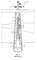
- a typical wireline-retrievable gas lift system 10 is shown in Figure 1 . Operators inject compressed gas G into the annulus 22 between a production tubing string 20 and the casing 24 within a cased wellbore 26. A valve system 12 supplies the injection gas G from the surface and allows produced fluid to exit the gas lift system 10.
- Gas lift valves 40 are one-way valves that allow gas flow from the annulus 22 into the production string 20 and to prevent gas flow from the production string 20 into the annulus 22.
- a production packer 14 located on the production string 20 forces the flow of production fluid P from a formation up through the production string 20 instead of up through the annulus 22. Additionally, the production packer 14 forces the gas flow from the annulus 22 into the production string 20 through the gas lift valves 40.
- the production fluid P flows from the formation into the wellbore 26 through casing perforations 28 and then flows into the production tubing string 20.
- compressed gas G is introduced into the annulus 22, and the gas G enters from the annulus 22 through ports 34 in the mandrel's side pockets 32.
- the gas lift valves 40 Disposed inside the side pockets 32, the gas lift valves 40 control the flow of injected gas I into the production string 20. As the injected gas I rises to the surface, it helps to lift the production fluid P up the production string 20 to the surface.
- Gas lift valves 40 have been used for many years to inject compressed gas into oil and gas wells to assist in the production to the surface.
- the valves 40 use metal bellows to convert pressure into movement. Injected gas acts on the bellows to open the valve 40, and the gas passes through a valve mechanism into the tubing string. As differential pressure is reduced on the bellows, the valve 40 can close.
- Two types of gas lift valves 40 use bellows.
- One type uses a non-gas charged, atmospheric bellows and requires a spring to close the valve mechanism.
- the other type of valve 40 uses an internal gas charge, usually nitrogen, in a volume dome to provide a closing force on the bellows.
- pressure differential on the bellows from injected high-pressure gas opens the valve mechanism.
- the atmospheric bellows is subjected to high differential pressures when the valve 40 is installed in a well and can be exposed to high operating gas injection pressure.
- a valve having the gas-charged bellows is subject to high internal bellows pressure during setting and prior to installation. Yet, once the gas-charged valve is installed, the differential pressure across the bellows is less than in the non-gas charged bellows during operation of the valve.
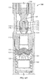
- FIGS 2A-2B Prior art gas lift valves 40a-b having gas-charged bellows are shown in Figures 2A-2B .
- Each of the gas lift valves 40a-b has upper and lower seals 44a-b separating a valve port 46, which is in communication with injection gas ports 48.
- a valve piston 52 is biased closed by a gas charge dome 50 and a bellows assembly (i.e., convoluted bellows 56 in Fig. 2A or edge-welded bellows system 57 in Fig. 2B ).
- the valve piston 52 moves relative to a valve seat 54 at the valve port 46 in response to pressure on the bellows 56 from the gas charge dome 50.
- a predetermined gas charge is applied to the dome 50 and bellows assembly ( i.e ., 56 or 57) biases the valve piston 52 against the valve seat 54 and close the valve port 46.
- a check valve 58 in the gas-lift valves 40 is positioned downstream from the valve piston 52, valve seat 54, and valve port 46.
- the check valve 58 keeps flow from the production string (not shown) from going through the injection ports 48 and back into the casing (annulus) through the valve port 46. Yet, the check valve 58 allows injected gas from the valve port 46 to pass out the gas injection ports 48.
- the bellows 56 on the valve 40a in Figure 2A is a convoluted bellows.
- a spring-activated gas lift valve may be available for standard sizes and capable of higher pressures, such a bellows-activated gas lift valve 40a with a convoluted bellows is not available for standard sizes of 1" and 1.5", while being capable of operating pressures higher than 2000-2500 PSI range. Instead, existing gas lift valves 40a using convoluted bellows are rated to a maximum operating injection pressure of 2000-2500 PSI.
- valve 40a is not capable of reaching high operating pressures. If exposed to higher pressures, the valve's convoluted bellows 56 would fail.
- the bellows 56 may snake by forming a wave when exposed to high differential internal pressure, or the bellows 56 may split the convolutions by flattening when exposed to high external pressures.
- rapid pressure changes can contract and expand the bellows until the bellow's material fails due to fatigue.
- the XLift gas lift valve available from Schlumberger has a bellows system for operating at high pressures.
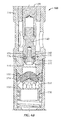
- An example of this bellows system 57 is shown on the gas lift valve 40b of Figure 2B .
- the edge-welded bellows system 57 is similar to that disclosed in U.S. Pat. No. 5,662,335 .
- two sets 60a-b of dual bellows each include a seal bellows 62 and a counter bellows 64.
- the counter bellows 64 equalizes pressure exerted on the seal bellows 62 by delivering pressure of the injection gas to the oil in the system.
- the valve piston 52 with its tungsten carbide ball on its distal end contacts the venturi seat 54, which acts as a positive stop for the gas lift valve 40b.
- None of the bellows 62, 64 of the bellows system 57 fully compresses.
- the arrangement of multiple bellows 62, 64 in the two sets 60a-b allow the gas lift valve to operate at higher pressures.
- the gas lift valve 40b must at least have a nominal size of 1.75-in. This requires the gas lift valve 40b to be used in a larger, custom designed gas lift mandrel, namely the XLG side pocket mandrel available from Schlumberger.
- the complexity of the bellows system 57 has obvious disadvantages in the construction and operation of the gas lift valve 40b.
- the subject matter of the present disclosure is directed to overcoming, or at least reducing the effects of, one or more of the problems set forth above.
- a gas lift apparatus may comprise a housing having a chamber, an inlet, and an outlet and a first seat disposed between the inlet and the outlet.
- the apparatus may comprise a piston movably disposed in the housing, the piston having a proximal end exposed to chamber pressure and a distal end exposed to inlet pressure, the distal end sliding relative to the first seat and selectively sealing fluid communication through the first seat.
- the apparatus may comprise a first edge-welded bellows disposed on the piston and separating the inlet pressure from the chamber pressure, the first edge-welded bellows fully compressing to a stacked height at a point when the distal end seals fluid communication through the first seat.
- the first edge-welded bellows fully compressed to the stacked height may stop the sliding of the distal end relative to the first seat.
- the apparatus may further comprise a check valve disposed in the housing, the check valve permitting fluid communication from the inlet to the outlet and restricting fluid communication from the outlet to the inlet.
- the first seat may comprise an internal surface
- the distal end of the piston may comprise a seal disposed on an external surface of the distal end, the seal biased transversely to an axis of the piston and engaging the internal surface when disposed adjacent thereto.
- the seal may comprise a sealing ring and a resilient ring disposed in a groove defined around the external surface, the resilient ring biasing the sealing ring away from the external surface.
- the seal may comprise a spring-loaded cup seal having a lip biased away from the external surface.
- the distal end may comprise an external surface
- the first seat may comprise a seal disposed on an internal surface, the seal biased transversely to an axis of the piston and engaging the external surface of the distal end when disposed adjacent thereto.
- the seal may comprise a sealing ring and a resilient ring disposed in a groove defined around the internal surface, the resilient ring biasing the sealing ring away from the internal surface.
- the seal may comprise a spring-loaded cup seal having a lip biased away from the internal surface.
- the first edge-welded bellows may comprise a plurality of edge-welded diaphragms being stacked on top of one another when fully compressed in the stacked height.
- the chamber may comprise an end wall having a shape corresponding to one of the edge-welded diaphragms and having one end of the first edge-welded bellows affixed thereto; and the piston may comprise a shoulder having a shape corresponding to one of the edge-welded diaphragms and having one end of the first edge-welded bellows affixed thereto.
- the apparatus may further comprise a second edge-welded bellows disposed on the piston and separating the inlet pressure from the chamber pressure, the second edge-welded bellows fully compressing to a stacked height when the distal end is distanced away from the first seat.
- the piston may comprise an internal passage communicating a first interior of the first edge-welded bellows with a second interior of the second edge-welded bellows.
- the first and second interiors may communicate a pressure differential between the inlet pressure and the chamber pressure via the internal passage.
- An incompressible fluid may fill the first and second interiors and the internal passage.
- a gas lift apparatus may comprise a housing having a chamber, an inlet, and an outlet and having an internal surface disposed between the inlet and the outlet.
- the apparatus may comprise a piston movably disposed along an axis in the housing, the piston having a proximal end exposed to chamber pressure and having a distal end exposed to inlet pressure, the distal end having an external surface selectively movable relative to the internal surface.
- the apparatus may comprise at least one bellows disposed on the piston and separating the inlet pressure from the chamber pressure.
- the apparatus may comprise a seal configured between the internal and external surfaces, the seal selectively sealing fluid communication from the inlet to the outlet and allowing the internal surface to slide relative to the external surface with the movement of the piston along the axis.
- the apparatus may further comprise a check valve disposed in the housing, the check valve permitting fluid communication from the inlet to the outlet and restricting fluid communication from the outlet to the inlet.
- the seal may be disposed on the external surface of the distal end, the seal biased transversely to the axis of the piston and engaging the internal surface of the housing when disposed adjacent thereto.
- the seal may comprise a sealing ring and a resilient ring disposed in a groove defined around the external surface, the resilient ring biasing the sealing ring away from the external surface.
- the seal may comprise a spring-loaded cup seal having a lip biased away from the external surface.
- the seal may be disposed on the internal surface of the housing, the seal biased transversely to the axis of the piston and engaging the external surface of the distal end when disposed adjacent thereto.
- the seal may comprise a sealing ring and a resilient ring disposed in a groove defined around the internal surface of the housing, the resilient ring biasing the sealing ring away from the internal surface.
- the seal may comprise a spring-loaded cup seal having a lip biased away from the internal surface.
- the at least one bellows may comprise a first edge-welded bellows fully compressing to a stacked height at a point when the seal seals fluid communication and stopping the movement of the piston in a first direction along the axis.
- the first edge-welded bellows may comprise a plurality of edge-welded diaphragms being stacked on top of one another when fully compressed in the stacked height.
- the chamber may comprise an end wall having a shape corresponding to one of the edge-welded diaphragms and having one end of the first edge-welded bellows affixed thereto; and the piston may comprise a shoulder having a shape corresponding to one of the edge-welded diaphragms and having one end of the first edge-welded bellows affixed thereto.
- the at least one bellows may comprise a second edge-welded bellows disposed on the piston and separating the inlet pressure from the chamber pressure, the second edge-welded bellows fully compressing to a stacked height when the external surface is distanced away from the internal surface and stopping the movement of the piston in a second direction along the axis.
- the piston may comprise an internal passage communicating a first interior of the first edge-welded bellows with a second interior of the second edge-welded bellows.
- the first and second interiors may communicate a pressure differential between the inlet pressure and the chamber pressure via the internal passage.
- An incompressible fluid may fill the first and second interiors and the internal passage.
- An apparatus for gas lift of production fluid in a production string has a gas lift valve that disposes in a mandrel downhole.
- the valve has a housing with a chamber, an inlet, and an outlet.
- a seat is disposed in the housing between the inlet and the outlet, and a piston is movably disposed in the housing relative to the seat for opening and closing the valve.
- the piston's proximal end is exposed to the chamber, while the piston's distal end can selectively seal with the seat to close fluid communication from the inlet to the outlet.
- the seat and the piston's distal end can engage with a captive sliding seal during operation of the valve.
- the seat is an inner cylindrical wall of the housing, and the piston's distal end has a captive sliding seal disposed thereabout that engages the wall when the distal end is inserted through the seat during closure of the valve.
- the wall and seal configuration are reversed so that the piston's distal end has an external surface that engages a captive sliding seal on the housing when moved relative thereto.
- Different types of captive sliding seals can be used, having elastomeric biasing elements or spring-loaded basing elements.
- an edge-welded bellows is disposed on the piston and separates inlet pressure at the inlet from chamber pressure at the chamber.
- the first edge-welded bellows fully compresses to a stacked height when the piston's distal end seals with the seat. In this way, the stacked edge-welded bellows stops movement of the piston's distal end inside the seat so there is no need for a mechanical stop to limit the piston's movement as conventionally required. Consequently, a more dynamic seal can be achieved at closing as noted above.
- Another edge-welded bellows can also be disposed on the piston and can separate the inlet pressure from the chamber pressure.
- the two bellows can have interiors communicating with one another via an internal passage in the piston.
- the two bellows operate in tandem with one extending when the other contracts and vice versa.
- An incompressible fluid such as silicon oil, fills the interiors and the passage and can move from one bellows to the other to transfer the pressure differential between the inlet pressure and the chamber pressure.
- this second bellows fully compresses to a stacked height when the distal end is distanced away from with the seat. This stops movement of the distal end away from the seat during opening and stops further extension of the first bellows.
- Fig. 1 illustrates a gas lift system
- Figs. 2A-2B illustrate gas lift valves according to the prior art.
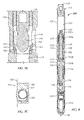
- Fig. 3 illustrates a cross-section of a gas lift valve according to the present disclosure having a single edge-welded bellow.
- Fig. 4 shows an edge-welded bellows according to the present disclosure.
- Figs. 5A-5C shows the edge-welded bellows in three states.
- Figs. 6A-6B illustrates portion of the gas lift valve, showing the valve member in stages of sealing.
- Fig. 7A illustrates portion of the gas lift valve, showing a reverse sealing arrangement than that shown in Figures 6A-6B .
- Fig. 7B illustrates portion of the gas lift valve, showing another sealing arrangement having a spring-loaded cup seal.
- Fig. 7C is a detailed view of a spring-loaded cup seal having a lip biased transversely to the valve's axis.
- Fig. 8 illustrates a cross-section of a gas lift valve according to the present disclosure having dual edge-welded bellows.
- Figs. 9A-9B illustrates portion of the gas lift valve, showing the dual bellows during stages of operation.
- a gas lift valve 100 has a housing 110 that sets in an appropriate mandrel (not shown).
- the gas lift valve 100 can be a tubing-retrievable or a wireline-retrievable gas lift valve used in an appropriate mandrel.
- the housing 110 has seals 114a-b to isolate fluid communication of injected gas from a port (not shown) on the mandrel into a valve port 116 of the valve 100.
- Various components of the valve 100 such as a latch connected to the top end, are not shown, but would be present, as one skilled in the art would be appreciated.
- a dome chamber 120 and an edge-welded bellows 160 bias a valve piston 130 and control the flow of the injected gas from the valve port 116 to injection ports 118.
- the dome chamber 120 holds a compressed gas, typically nitrogen, which is filled through a port 113 in a top member 112.
- This port 113 typically has a core valve (not shown) for filing the chamber 120 and typically has an additional tail plug (not shown) installed during assembly.
- the bellows 160 separates the compressed gas in the dome chamber 120 from communicating with the valve port 116 and injection port 118 so pressure can be maintained in the chamber 120.
- an example of the edge-welded bellows 160 for the gas lift valve has several stamped diaphragms 162 and 164 weld together. These stamped diaphragms 162 and 164 are made from metal sheeting using hydraulic stamping techniques. The thickness, shape, and material of these stamped diaphragms 162 and 164 can be configured to suite the pressure, stroke length, spring rate, temperature, and other factors of the application at hand. Various ripple profiles and the diameters of the inside and outside edges 166 and 168 of the stamped diaphragms 162 and 164 can dictate the performance of the bellows 160 so that they are preferably designed using known techniques for the desired application.
- stamped diaphragms 162 and 164 are stacked back-to-back (male to female) and are welded together at inside and outside diameters 166 and 168 using plasma, laser, arc, or electron beam welding.
- the upper and lower ends on the bellows 160 can have end plates or flanges welded thereto, or the ends of the bellows 160 can be directly affixed to portions of the piston 130 and housing 110, as shown in Figure 3 .
- an upper seal 132 can engage an upper seat 122 of the dome chamber 120 when the piston 130 is at its pinnacle position ( i.e. , fully biased open).
- the upper seal 132 is preferably made of a metal material, such as copper, which is less hard than the upper seat 122.
- the valve piston 130 can be grooved or slotted along portion of its length to fit in complementary grooves or slots inside the housing 110 to prevent rotation of the valve piston 130.
- the valve piston 130 Opposite the bellows 160, the valve piston 130 has a distal end 140 that moves relative to an inner seating surface 115 of the housing 110.
- the distal end 140 has an outer surface 142, which can be cylindrical in shape to match the seating surface 115 with a close clearance.
- the housing's inner surface 115 and the distal end's outer surface 142 are disposed axially along the axis of the valve 100 so that the outer surface 142 can slide with tight clearance relative to the inside surface 115 of the housing 110.
- a suitable clearance for the two surfaces 115 and 142 would be about ⁇ 0.002-inch, although other clearances could be used for a given implementation.
- a captive sliding seal 170 on the piston's distal end 140 engages or disengages the surface 115 to close and open communication from the valve port 116 to the injection ports 118.
- the captive sliding seal 170 is installed in a groove around the outside surface 142 of the distal end 140 and moves with the end 140 relative to the internal seating surface 115 of the housing 110 near the inlet 116. (Further details of the captive sliding seal 170 are discussed below with reference to Figures 6A-6B .)
- any injected gas passing through the seating surface 115 when the distal end 140 is distanced opened therefrom can overcome the bias of a reverse check valve 150 and exit the injection ports 118 to enter the production tubing for the gas lift operation.
- the check valve 150 can be a dart valve with ports 151.
- a spring 156 biases the check valve 150 toward a seat, which has an elastomeric component 152 and a retainer 154, although other types of seals could be used.
- the bellows 160 is disposed on the valve piston 130 in an ancillary chamber 124 separated from the dome chamber 120 by the chamber seat 122.
- the valve 100 uses this edge-welded bellow 160 as the membrane between the dome chamber 120 and the annulus injection pressure that opens the valve 100.
- the bellows 160 is an edge-welded bellows, as discussed below.
- the edge-welded bellows 160 is fully compressed when valve 100 is closed, and the bellows 160 goes to expanded state as the valve 100 is being opened by the differential between injection and tubing pressures.
- the single edge-welded bellows 140 moves the piston 130 depending on the pressure difference between the dome pressure and injection pressure.
- pressure in the dome chamber 120 acts on the bellows' outside surface while injection pressure acts internally. If there is no injection pressure, the valve 100 is in the closed position, and the bellows 160 is compressed completely to its solid height (like a fully compressed spring). This is unlike the standard convoluted bellows, which is in an expanded state when the gas lift valve is closed.
- the bellows 160 is configured to fully compress so that the piston's distal end 140 engages in the sealing surface 115, closing the valve 100.
- compressed gas from the casing-tubing annulus (not illustrated) is injected from the surface, the gas enters the inlet 116 during operation of the valve 100.
- the compressed gas travels internally in the space between the housing 110 and the piston 130 and enters the interior of the bellows 160.
- the compressed gas acts against the internal surfaces of the bellows 160, pushing the convolutions against the external dome chamber pressure inside the bellows 160.
- pressurized gas and any oil or the like in the dome 120 provides a counteracting force on the external surface of the bellows 160.
- the dome chamber 120 is filled with appropriate amount of silicone oil.
- silicone oil protects the bellows 160 from internal-injection pressure and prevents valve chatter due to any non-uniform injection flow or pressure.
- the copper seal 132 on the valve piston 120 reaches the chamber's seat 122. Expansion of the bellows 160 stops and silicone oil is trapped in the volume between the bellow's outside dimension and the dome's internal diameter. In this open condition, the copper seal 132 provides a bellows expansion stop, and the incompressible oil prevents bellows convolution deformations and failure.
- the bellows 160 stays close to pressure balance so the convolutions are protected from overstressing. It is believed that the gas lift valve 100 of Figure 3 may be able to operate at least in pressures as high as 2,500 PSI.
- the gas lift valve 100 can still have 1" and 1.5" valve diameter.
- the captive sliding seal 170 is not sensitive to explosive decompression.
- the bellows 160 may not be perfectly pressure balanced. However, any pressure difference is not very large, and the pressure difference for various seal diameters and tubing pressure combinations may be expected to range within about 20%. This means that the injection pressure acting on the bellow's surface area minus the seat's ID surface area may be higher than the dome pressure in chamber 120.
- the bellows 160 itself acts as a stop, which is reaches its stack height and keeps the piston's distal end 140 from inserting further in the seat 115.
- gas lift valves use a tungsten carbide ball and seat to open and close flow through the valve as noted previously. Engagement of the ball with the seat acts as the "stop” for the piston in conventional gas lift valves. Since the edge-welded bellows 160 acts as the "stop,” the disclosed gas lift valve 100 can use the captive sliding seal 170, which is a different type of sealing mechanism than typically used.
- the captive sliding seal 170 includes a cap 172 affixed in the opening 144 on the piston's distal end 140.
- the cap 172 holds a sealing element 176 and a biasing element 174 on the end 140.
- the biasing element 174 is an O-ring seal, which can be composed of a suitable elastomer for the application.
- the sealing element 176 can be a ring composed of a polymer, such as polytetrafluoroethylene (PTFE), Teflon®, or the like. (TEFLON is a registered trademark of E. I. Du Pont De Nemours and Company Corporation.)
- the biasing element 174 is held captive in a groove 173 behind the sealing element 176.
- the sealing element 176 is energized by the biasing element 174 and extends outward from the distal end's outer surface 142 so it can transversely engage the seating surface 115.
- the sealing element 176 as shown in Figure 6B creates a seal as it engages the surface 115 and is biased by the biasing element 174.
- the groove 173 helps anchor the elements 174 and 176 to prevent the seal 170 from displacing during opening of the valve (100).
- Channels 175 in the cap 172 communicate from the end of the cap 172 to an area of the groove 173 between the biasing and sealing elements 174 and 176.
- the channels 175 are intended to equalize the pressure on the elements 174 and 176 and may be optional depending on the implementation. As will be appreciated, differential pressure across the seal 170 can be significant and appropriate anchoring of the seal 170 can be necessary for proper functioning.
- the captive sliding seal 170 can be configured in a reverse arrangement on the gas lift valve 100.
- the cap 172 is a ring element that threads into the housing 110 at the sealing surface 115. (Other means for holding the cap 172 could be used, such as external retention pins or the like.)
- the sealing surface 115 may be an integral part of the housing 110 as before, or a base element 119 as shown can thread into the housing 110 to provide the surface 115 and engage the cap 172.
- the cap 172 holds the biasing element 174 and the sealing element 176 captive in a groove 173. (Here, the groove 173 is formed between the cap 172 and the base element 119.)
- the piston's distal end 140 has an outer surface 142, which can be cylindrical and can have a tight clearance to the internal diameter of the housing's sealing surface 115.
- the captive sliding seal 170 engages the distal end's outer surface 142 to seal off fluid flow from the inlet ports 116 to the check valve 150. This arrangement is especially useful when the valve's performance requires a relatively small diameter for the distal end 140 because the small diameter would make retaining biasing and sealing elements on the distal end 140 problematic.
- FIG. 7B Another captive sealing arrangement is shown in Figure 7B , which illustrates portion of the gas lift valve 100.
- a captive sealing seat 180 is disposed in the housing 110 between the inlet 116 and the housing's inner surface 115.
- the distal end 140 has an outer surface 142, which can be cylindrical in shape to match the seating surface 115 with a close clearance.
- the distal end 140 attached to the piston 130 can travel through the captive sealing seat 180 to open and close the valve 100, and the end's outer surface 142 engages the captive sealing seat 180.
- the captive sealing seat 180 includes a retaining ring 182 and an energized lip seal 184.
- the retaining ring 182 can be composed of non-elastomeric material, such as PTFE or metal. As shown, the retaining ring 182 can be held in the housing 110 with retention pins (not shown) inserted externally through retention holes 183 in the housing. Of course, other means known in the art could be used to retain the ring 182. For example, the ring 182 may thread into the housing 110 to hole the seal 184 captive.
- the energized lip seal 184 can be a spring-loaded cup seal disposed in a rod and piston seal configuration.
- the resiliency of the seal 184 therefore acts transversely to the piston's longitudinal axis. In this way, the seal 184 presses outward into the valve's seating surface 115 and acts transversely to the seating direction of the distal end 170 as shown in Figure 7B .
- the shape and geometry of the seal 184 is preferably configured, as much as possible, to avoid failure. All the same, the seal 184 offers another type of sealing configuration for the sliding captive seal of the present disclosure.
- Figure 7C shows one arrangement of a spring-loaded cup seal for the seal 184 on the sealing arrangement of Figure 7B .
- the spring-loaded cup seal 184 can have a jacket 185, a coil spring 187, and a hat ring 189.
- the jacket 185 and hat ring 186 are both preferably composed of non-elastomeric materials, and the coil spring 187 is preferably composed of corrosive resistant metal.
- the seal's internal lip is preferably thick to prevent possible oscillation when exposed to high flow rates of gas or water through the valve 100. Further details of such a captive sealing arrangement having such a spring-loaded cup seal and the like are provided in copending U.S. Pat. Appl. Ser. No. 13/027,676 , entitled “Self-Boosting, Non-Elastomeric Resilient Seal for Check Seal” and filed 15-FEB-2011, which is incorporated herein by reference in its entirety.
- the sealing arrangements of Figures 6A-6B and 7A-7C for the captive sliding seals 170/180 allow the distal end 140 to slide with the axial movement of the piston 130 through the valve's surrounding surface 115 when opening and closing the valve.
- the captive sliding seals 170/180 can avoid problems that conventional seals experience from explosive decompression.
- the captive sliding seals 170/180 (especially the seal arrangement of Figs. 6A-6B ) can resist erosion that may occur when the valve 100 is operated.
- both the piston's distal end 140 and the housing's sealing surface 115 can have a captive sliding seal, as long as the two seals are arranged so as not to engage one another when the valve 100 is fully closed.
- either the distal end 140 or the surface 115 may have more than one captive sliding seal disclosed herein.
- Figure 8 illustrates another gas lift valve 100 according to the present disclosure.
- the valve 100 has dual edge-welded bellows 160a-b disposed on the piston 130.
- the piston 130 defines an internal passage having a main passage 135 and ancillary passages 137, which interconnect the interiors of the bellows 160a-b as discussed later.
- Figures 9A-9B illustrate portion of the gas lift valve 100, showing the dual bellows 160a-b during stages of operation.
- the gas lift valve 100 has seals 114a-b on the housing 110 to isolate fluid communication of injected gas into a valve port 116 of the valve 100.
- a dome chamber 120 and the dual edge-welded bellows 160a-b then bias a valve piston 130 and control the flow of the injected gas from the valve port 116 to injection ports 118.
- the dome chamber 120 holds a compressed gas, typically nitrogen, which is filled through a port 113 in a top member 112 and later sealed with a plug (not shown).
- the two bellows 160a-b separate the compressed gas in the chamber 120 from communicating with the valve port 116 and injection port 118 so pressure can be maintained in the chamber 120.
- both bellows 160a-b are very close to internal/external pressure balance, which is helpful to protect the bellows 160a-b.
- an upper connector or shoulder 131a on the piston 130 has one end of the upper bellows 160a affixed thereto; the other end of the upper bellows 160a affixes to the top surface or end wall on an intermediate body 124.
- This upper connector 131a and the exterior of the upper bellows 160a are exposed to pressure in the dome chamber 120.
- the valve piston 130 also has a lower connector or shoulder 131b to which one end of the lower bellows 160b affixes; the other end of the lower bellows 160b affixes to the bottom surface or end wall on the intermediate body 124.
- the lower connector 131b and the exterior of the lower bellows 160b are exposed to pressure in an ancillary chamber 117. Pressure acting outside the upper bellows 160a transfers via the piston's passages 135 and 137 to the interior of the lower bellows 160b. The reverse is also true.
- the valve piston 130 also has a distal end 140 that moves relative to an inner seating surface 115 of the housing 110.
- a captive sliding seal 170 on the distal end 140 engages or disengages the surface 115 to close and open communication from the valve port 116 to the injection ports 118.
- this valve 100 of Figure 8 can have any of the other seal arrangements disclosed herein.
- Any injected gas passing through the seating surface 115 when the distal end 140 is distanced opened therefrom can overcome the bias of a reverse check valve 150 and exit the injection ports 118 to enter the production tubing for the gas lift operation.
- the bellows 160a-b and the piston 130 are shown relative to the intermediate body 124 when the valve 100 is fully open ( Fig. 9A ) and fully closed ( Fig. 9B ).
- the lower bellows 160b is configured to fully compress when the distal end (140) disengages from the sealing surface (115), opening the valve 100.
- the upper below 160a is configured to extend when the valve is open.
- the upper bellows 160a is configured to fully compress when the distal end (140) engages in the sealing surface (115), closing the valve 100.
- the lower bellows 160b is configured to extend when the valve is closed.
- each bellows 160a-b welds to the bellow connector 131a-b, which has a surface machined to match the bellow's convolution geometry.
- Opposite ends of each bellow 160a-b are welded to mating surfaces 125a-b on the intermediate body 124, which has its surfaces 125a-b machined to match the bellow's convolution geometry.
- the matching surfaces 125a-b on the body 124 and the surfaces on the connectors 131a-b allow the bellows 160a-b to be compressed to solid height against the surfaces for full contact without deformation/damage to bellows' convolutions.
- the bottom and top surfaces 125a-b of the intermediate body 124 match the shape of an edge-welded diaphragm of the bellows 160a-b
- the surfaces of the caps 131a-b also match the shape of an edge-welded diaphragm of the bellows 160a-b.
- the bellows 160a-b are filled with an incompressible fluid, such as silicone oil.
- an incompressible fluid such as silicone oil.
- the lower bellow 160a is fully compressed during the filling.
- plugs 129 and 133 are installed respectively in opening 128 in the intermediate body 124 and in the opening 133 on the upper connector 131a. Once filled, oil can then flow between the upper and lower bellows 160a-b depending on which bellow pressure is acting through the communication passages 135 and 137 in the piston 130.
- the chamber 120 is charged with compressed gas, such as nitrogen, at a desired high pressure through the end piece (112), whose opening (113) is plugged after filing. With only the dome pressure, the pressure in the chamber 120 acts on the upper bellow's external surface, causing it to fully compress ( Fig. 9B ) to its solid length (similar to a fully compressed spring) when injection pressure is not present.
- compressed gas such as nitrogen
- the pressure difference on the bellows 160a-b fully compresses the upper bellows 160a and fully extend the lower bellows 160b to move the piston's distal end 140 against the sealing surface (115).
- the captive sliding seal 170 engages seating surface (115), thereby preventing injection gas from passing through the valve 100 to the outlet (118). This represents the "closed" condition of the valve 100.
- the bellows 160a When the upper bellows 160a is fully compressed, the bellows 160a reverts to its solid height, and no more oil flow occurs once the upper bellow 160a is fully compressed.
- the full compression protects the bellows 160a from deformation caused by the external dome pressure when the gas lift valve 100 is closed.
- the compressed upper bellows 160a acts as a stop to the piston's movement.
- the dynamic seal can be used as discussed herein with its advantages over conventional sealing engagements.
- the valve piston 130 does not move, and the valve 100 remains closed.
- the piston 130 moves upward, and the gas-lift valve 100 opens.
- the external and internal pressure difference on the bellows 160a-b may partially contract the upper bellows 160a and extend the lower bellows 160b to move the piston's distal end 140 away from the sealing surface 115.
- Flow is now established through the valve 100, pushing the reverse check dart 150 to the open position and allowing gas to exit the valve 100 through the nose ports 118.
- the bellow 160b is fully protected from deformation and damage since it acts as a piece of metal cylinder.
- the upper bellow 160a is now fully expanded to its free length. Regardless of further injection pressure increase, the oil stops flowing from the lower bellow 160a to the upper bellow 160b, and pressure does not transmit to the upper bellow 160a because movement is stopped by the stacked lower bellow 160b.
- Bellow protection uses the full compression to solid stack height for both bellows 160a-b during valve operation when the valve 100 is open or closed.
- Full compression to solid height means that the bellows 160a-b are acting as a mechanical stop.
- the upper bellow 160a is a mechanical stop.
- the lower bellow 160b is a mechanical stop in the opposite direction.
- the captive sliding seal 170 can therefore act dynamical as a sliding seal that can seal flow while allowing the bellows 160b to fully compress.
- the gas lift valve 100 can be used for deepwater gas lift applications and applications involving very high injection pressures, although any number of implementations may benefit from the valve 100.
- the pressure rating of the gas lift valve 100 can be increased by using bellows 160 composed of an Inconel ® alloy (e.g., Inconel ® alloy 718) rather than a Monel ® alloy. (INCONEL and MONEL are registered trademarks of Special Metals Corporation).
- other techniques known in the art can help keep the bellows 160 from being damaged when operated with high differential pressure.
- valve 100 of Figures 3 or 8 can be used on either valve 100 of Figures 3 or 8 .
- gas lift valves 100 have been shown and described primarily as wireline-retrievable gas lift valves intended to install in a side pocket mandrel. As will be appreciated, this is not strictly necessary, and the disclosed valves 100 can be used as a wireline or tubing-retrievable apparatus and can be configured for use with any type of mandrel, even conventional mandrels having external mounts.
Landscapes
- Life Sciences & Earth Sciences (AREA)
- Engineering & Computer Science (AREA)
- Geology (AREA)
- Mining & Mineral Resources (AREA)
- Physics & Mathematics (AREA)
- Environmental & Geological Engineering (AREA)
- Fluid Mechanics (AREA)
- General Life Sciences & Earth Sciences (AREA)
- Geochemistry & Mineralogy (AREA)
- Fluid-Driven Valves (AREA)
Abstract
Description
- To obtain hydrocarbon fluids from an earth formation, a wellbore is drilled into an area of interest within a formation. The wellbore may then be "completed" by inserting casing in the wellbore and setting the casing using cement. Alternatively, the wellbore may remain uncased as an "open hole"), or it may be only partially cased. Regardless of the form of the wellbore, production tubing is run into the wellbore to convey production fluid (e.g., hydrocarbon fluid, which may also include water) to the surface.
- Often, pressure within the wellbore is insufficient to cause the production fluid to naturally rise through the production tubing to the surface. In these cases, an artificial lift system can be used to carry the production fluid to the surface. One type of artificial lift system is a gas lift system, of which there are two primary: tubing-retrievable gas lift systems and wireline-retrievable gas lift systems. Each type of gas lift system uses several gas lift valves spaced along the production tubing. The gas lift valves allow gas to flow from the annulus into the production tubing so the gas can lift production fluid in the production tubing. Yet, the gas lift valves prevent fluid to flow from the production tubing into the annulus.
- A typical wireline-retrievable
gas lift system 10 is shown inFigure 1 . Operators inject compressed gas G into theannulus 22 between aproduction tubing string 20 and the casing 24 within acased wellbore 26. Avalve system 12 supplies the injection gas G from the surface and allows produced fluid to exit thegas lift system 10. -
Side pocket mandrels 30 spaced along theproduction string 20 holdgas lift valves 40 withinside pockets 32. As noted previously, thegas lift valves 40 are one-way valves that allow gas flow from theannulus 22 into theproduction string 20 and to prevent gas flow from theproduction string 20 into theannulus 22. - A production packer 14 located on the
production string 20 forces the flow of production fluid P from a formation up through theproduction string 20 instead of up through theannulus 22. Additionally, the production packer 14 forces the gas flow from theannulus 22 into theproduction string 20 through thegas lift valves 40. - In operation, the production fluid P flows from the formation into the
wellbore 26 throughcasing perforations 28 and then flows into theproduction tubing string 20. When it is desired to lift the production fluid P, compressed gas G is introduced into theannulus 22, and the gas G enters from theannulus 22 throughports 34 in the mandrel'sside pockets 32. Disposed inside theside pockets 32, thegas lift valves 40 control the flow of injected gas I into theproduction string 20. As the injected gas I rises to the surface, it helps to lift the production fluid P up theproduction string 20 to the surface. -
Gas lift valves 40 have been used for many years to inject compressed gas into oil and gas wells to assist in the production to the surface. Thevalves 40 use metal bellows to convert pressure into movement. Injected gas acts on the bellows to open thevalve 40, and the gas passes through a valve mechanism into the tubing string. As differential pressure is reduced on the bellows, thevalve 40 can close. - Two types of
gas lift valves 40 use bellows. One type uses a non-gas charged, atmospheric bellows and requires a spring to close the valve mechanism. The other type ofvalve 40 uses an internal gas charge, usually nitrogen, in a volume dome to provide a closing force on the bellows. In both valve configurations, pressure differential on the bellows from injected high-pressure gas opens the valve mechanism. In the case of a valve having the non-gas charged bellows, the atmospheric bellows is subjected to high differential pressures when thevalve 40 is installed in a well and can be exposed to high operating gas injection pressure. By contrast, a valve having the gas-charged bellows is subject to high internal bellows pressure during setting and prior to installation. Yet, once the gas-charged valve is installed, the differential pressure across the bellows is less than in the non-gas charged bellows during operation of the valve. - Prior art
gas lift valves 40a-b having gas-charged bellows are shown inFigures 2A-2B . Each of thegas lift valves 40a-b has upper andlower seals 44a-b separating avalve port 46, which is in communication withinjection gas ports 48. Avalve piston 52 is biased closed by agas charge dome 50 and a bellows assembly (i.e., convolutedbellows 56 inFig. 2A or edge-welded bellows system 57 inFig. 2B ). At its distal end, thevalve piston 52 moves relative to avalve seat 54 at thevalve port 46 in response to pressure on thebellows 56 from thegas charge dome 50. A predetermined gas charge is applied to thedome 50 and bellows assembly (i.e., 56 or 57) biases thevalve piston 52 against thevalve seat 54 and close thevalve port 46. - A
check valve 58 in the gas-lift valves 40 is positioned downstream from thevalve piston 52,valve seat 54, andvalve port 46. Thecheck valve 58 keeps flow from the production string (not shown) from going through theinjection ports 48 and back into the casing (annulus) through thevalve port 46. Yet, thecheck valve 58 allows injected gas from thevalve port 46 to pass out thegas injection ports 48. - The
bellows 56 on thevalve 40a inFigure 2A is a convoluted bellows. Although a spring-activated gas lift valve may be available for standard sizes and capable of higher pressures, such a bellows-activatedgas lift valve 40a with a convoluted bellows is not available for standard sizes of 1" and 1.5", while being capable of operating pressures higher than 2000-2500 PSI range. Instead, existinggas lift valves 40a using convoluted bellows are rated to a maximum operating injection pressure of 2000-2500 PSI. - As a result, such a
valve 40a is not capable of reaching high operating pressures. If exposed to higher pressures, the valve's convolutedbellows 56 would fail. For example, thebellows 56 may snake by forming a wave when exposed to high differential internal pressure, or thebellows 56 may split the convolutions by flattening when exposed to high external pressures. Finally, rapid pressure changes can contract and expand the bellows until the bellow's material fails due to fatigue. - Although a working pressure no higher than 2000-25000 PSI may be acceptable in some application, operators want to use gas lift system in higher working pressure of up to 5000-6000 PSI, for example. Unfortunately, high differential pressure across a bellows during operation reduces its cycle life. Therefore, existing gas lift valves and bellows are not designed to operate with set pressures or in operating pressures in excess of 2000 PSI without severe failure risks.
- As one exception, the XLift gas lift valve available from Schlumberger has a bellows system for operating at high pressures. An example of this
bellows system 57 is shown on thegas lift valve 40b ofFigure 2B . The edge-welded bellows system 57 is similar to that disclosed inU.S. Pat. No. 5,662,335 . As shown, twosets 60a-b of dual bellows each include aseal bellows 62 and acounter bellows 64. Thecounter bellows 64 equalizes pressure exerted on theseal bellows 62 by delivering pressure of the injection gas to the oil in the system. - During operation, the
valve piston 52 with its tungsten carbide ball on its distal end contacts theventuri seat 54, which acts as a positive stop for thegas lift valve 40b. None of thebellows bellows system 57 fully compresses. In the end, the arrangement ofmultiple bellows sets 60a-b allow the gas lift valve to operate at higher pressures. Due to the requirements of thebellows system 57, however, thegas lift valve 40b must at least have a nominal size of 1.75-in. This requires thegas lift valve 40b to be used in a larger, custom designed gas lift mandrel, namely the XLG side pocket mandrel available from Schlumberger. Additionally, the complexity of thebellows system 57 has obvious disadvantages in the construction and operation of thegas lift valve 40b. - The subject matter of the present disclosure is directed to overcoming, or at least reducing the effects of, one or more of the problems set forth above.
- According to a first aspect of the invention, there is provided a gas lift apparatus. The apparatus may comprisea housing having a chamber, an inlet, and an outlet and a first seat disposed between the inlet and the outlet. The apparatus may comprise a piston movably disposed in the housing, the piston having a proximal end exposed to chamber pressure and a distal end exposed to inlet pressure, the distal end sliding relative to the first seat and selectively sealing fluid communication through the first seat. The apparatus may comprise a first edge-welded bellows disposed on the piston and separating the inlet pressure from the chamber pressure, the first edge-welded bellows fully compressing to a stacked height at a point when the distal end seals fluid communication through the first seat.
- The first edge-welded bellows fully compressed to the stacked height may stop the sliding of the distal end relative to the first seat.
- The apparatus may further comprise a check valve disposed in the housing, the check valve permitting fluid communication from the inlet to the outlet and restricting fluid communication from the outlet to the inlet.
- The first seat may comprise an internal surface, and the distal end of the piston may comprise a seal disposed on an external surface of the distal end, the seal biased transversely to an axis of the piston and engaging the internal surface when disposed adjacent thereto.
- The seal may comprise a sealing ring and a resilient ring disposed in a groove defined around the external surface, the resilient ring biasing the sealing ring away from the external surface.
- The seal may comprise a spring-loaded cup seal having a lip biased away from the external surface.
- The distal end may comprise an external surface, and the first seat may comprise a seal disposed on an internal surface, the seal biased transversely to an axis of the piston and engaging the external surface of the distal end when disposed adjacent thereto.
- The seal may comprise a sealing ring and a resilient ring disposed in a groove defined around the internal surface, the resilient ring biasing the sealing ring away from the internal surface.
- The seal may comprise a spring-loaded cup seal having a lip biased away from the internal surface.
- The first edge-welded bellows may comprise a plurality of edge-welded diaphragms being stacked on top of one another when fully compressed in the stacked height.
- The chamber may comprise an end wall having a shape corresponding to one of the edge-welded diaphragms and having one end of the first edge-welded bellows affixed thereto; and the piston may comprise a shoulder having a shape corresponding to one of the edge-welded diaphragms and having one end of the first edge-welded bellows affixed thereto.
- The apparatus may further comprise a second edge-welded bellows disposed on the piston and separating the inlet pressure from the chamber pressure, the second edge-welded bellows fully compressing to a stacked height when the distal end is distanced away from the first seat.
- The piston may comprise an internal passage communicating a first interior of the first edge-welded bellows with a second interior of the second edge-welded bellows.
- The first and second interiors may communicate a pressure differential between the inlet pressure and the chamber pressure via the internal passage.
- An incompressible fluid may fill the first and second interiors and the internal passage.
- According to a further aspect of the invention, there is provided a gas lift apparatus. The apparatus may comprise a housing having a chamber, an inlet, and an outlet and having an internal surface disposed between the inlet and the outlet. The apparatus may comprise a piston movably disposed along an axis in the housing, the piston having a proximal end exposed to chamber pressure and having a distal end exposed to inlet pressure, the distal end having an external surface selectively movable relative to the internal surface. The apparatus may comprise at least one bellows disposed on the piston and separating the inlet pressure from the chamber pressure. The apparatus may comprise a seal configured between the internal and external surfaces, the seal selectively sealing fluid communication from the inlet to the outlet and allowing the internal surface to slide relative to the external surface with the movement of the piston along the axis.
- The apparatus may further comprise a check valve disposed in the housing, the check valve permitting fluid communication from the inlet to the outlet and restricting fluid communication from the outlet to the inlet.
- The seal may be disposed on the external surface of the distal end, the seal biased transversely to the axis of the piston and engaging the internal surface of the housing when disposed adjacent thereto.
- The seal may comprise a sealing ring and a resilient ring disposed in a groove defined around the external surface, the resilient ring biasing the sealing ring away from the external surface.
- The seal may comprise a spring-loaded cup seal having a lip biased away from the external surface.
- The seal may be disposed on the internal surface of the housing, the seal biased transversely to the axis of the piston and engaging the external surface of the distal end when disposed adjacent thereto.
- The seal may comprise a sealing ring and a resilient ring disposed in a groove defined around the internal surface of the housing, the resilient ring biasing the sealing ring away from the internal surface.
- The seal may comprise a spring-loaded cup seal having a lip biased away from the internal surface.
- The at least one bellows may comprise a first edge-welded bellows fully compressing to a stacked height at a point when the seal seals fluid communication and stopping the movement of the piston in a first direction along the axis.
- The first edge-welded bellows may comprise a plurality of edge-welded diaphragms being stacked on top of one another when fully compressed in the stacked height.
- The chamber may comprise an end wall having a shape corresponding to one of the edge-welded diaphragms and having one end of the first edge-welded bellows affixed thereto; and the piston may comprise a shoulder having a shape corresponding to one of the edge-welded diaphragms and having one end of the first edge-welded bellows affixed thereto.
- The at least one bellows may comprisea second edge-welded bellows disposed on the piston and separating the inlet pressure from the chamber pressure, the second edge-welded bellows fully compressing to a stacked height when the external surface is distanced away from the internal surface and stopping the movement of the piston in a second direction along the axis.
- The piston may comprise an internal passage communicating a first interior of the first edge-welded bellows with a second interior of the second edge-welded bellows.
- The first and second interiors may communicate a pressure differential between the inlet pressure and the chamber pressure via the internal passage.
- An incompressible fluid may fill the first and second interiors and the internal passage.
- An apparatus for gas lift of production fluid in a production string has a gas lift valve that disposes in a mandrel downhole. The valve has a housing with a chamber, an inlet, and an outlet. A seat is disposed in the housing between the inlet and the outlet, and a piston is movably disposed in the housing relative to the seat for opening and closing the valve. The piston's proximal end is exposed to the chamber, while the piston's distal end can selectively seal with the seat to close fluid communication from the inlet to the outlet.
- The seat and the piston's distal end can engage with a captive sliding seal during operation of the valve. In one arrangement, the seat is an inner cylindrical wall of the housing, and the piston's distal end has a captive sliding seal disposed thereabout that engages the wall when the distal end is inserted through the seat during closure of the valve. In another arrangement, the wall and seal configuration are reversed so that the piston's distal end has an external surface that engages a captive sliding seal on the housing when moved relative thereto. Different types of captive sliding seals can be used, having elastomeric biasing elements or spring-loaded basing elements.
- To control movement of the piston, an edge-welded bellows is disposed on the piston and separates inlet pressure at the inlet from chamber pressure at the chamber. The first edge-welded bellows fully compresses to a stacked height when the piston's distal end seals with the seat. In this way, the stacked edge-welded bellows stops movement of the piston's distal end inside the seat so there is no need for a mechanical stop to limit the piston's movement as conventionally required. Consequently, a more dynamic seal can be achieved at closing as noted above.
- Another edge-welded bellows can also be disposed on the piston and can separate the inlet pressure from the chamber pressure. For example, the two bellows can have interiors communicating with one another via an internal passage in the piston. The two bellows operate in tandem with one extending when the other contracts and vice versa. An incompressible fluid, such as silicon oil, fills the interiors and the passage and can move from one bellows to the other to transfer the pressure differential between the inlet pressure and the chamber pressure. In contrast to the first bellows, this second bellows fully compresses to a stacked height when the distal end is distanced away from with the seat. This stops movement of the distal end away from the seat during opening and stops further extension of the first bellows.
- The foregoing summary is not intended to summarize each potential embodiment or every aspect of the present disclosure. It should be understood that the features defined above in accordance with any aspect of the present invention or below in relation to any specific embodiment of the invention may be utilized, either alone or in combination, with any other defined feature, in any other aspect or embodiment of the invention.
-
Fig. 1 illustrates a gas lift system. -
Figs. 2A-2B illustrate gas lift valves according to the prior art. -
Fig. 3 illustrates a cross-section of a gas lift valve according to the present disclosure having a single edge-welded bellow. -
Fig. 4 shows an edge-welded bellows according to the present disclosure. -
Figs. 5A-5C shows the edge-welded bellows in three states. -
Figs. 6A-6B illustrates portion of the gas lift valve, showing the valve member in stages of sealing. -
Fig. 7A illustrates portion of the gas lift valve, showing a reverse sealing arrangement than that shown inFigures 6A-6B . -
Fig. 7B illustrates portion of the gas lift valve, showing another sealing arrangement having a spring-loaded cup seal. -
Fig. 7C is a detailed view of a spring-loaded cup seal having a lip biased transversely to the valve's axis. -
Fig. 8 illustrates a cross-section of a gas lift valve according to the present disclosure having dual edge-welded bellows. -
Figs. 9A-9B illustrates portion of the gas lift valve, showing the dual bellows during stages of operation. - Referring to
Figure 3 , agas lift valve 100 has ahousing 110 that sets in an appropriate mandrel (not shown). In general, thegas lift valve 100 can be a tubing-retrievable or a wireline-retrievable gas lift valve used in an appropriate mandrel. Shown primarily here as wireline-retrievable, thehousing 110 hasseals 114a-b to isolate fluid communication of injected gas from a port (not shown) on the mandrel into avalve port 116 of thevalve 100. (Various components of thevalve 100, such as a latch connected to the top end, are not shown, but would be present, as one skilled in the art would be appreciated.) - Internally, a
dome chamber 120 and an edge-weldedbellows 160 bias avalve piston 130 and control the flow of the injected gas from thevalve port 116 to injection ports 118. Thedome chamber 120 holds a compressed gas, typically nitrogen, which is filled through aport 113 in atop member 112. Thisport 113 typically has a core valve (not shown) for filing thechamber 120 and typically has an additional tail plug (not shown) installed during assembly. - The bellows 160 separates the compressed gas in the
dome chamber 120 from communicating with thevalve port 116 and injection port 118 so pressure can be maintained in thechamber 120. As shown inFigure 4 , an example of the edge-weldedbellows 160 for the gas lift valve has several stampeddiaphragms diaphragms diaphragms outside edges diaphragms bellows 160 so that they are preferably designed using known techniques for the desired application. - These stamped
diaphragms outside diameters bellows 160 can have end plates or flanges welded thereto, or the ends of thebellows 160 can be directly affixed to portions of thepiston 130 andhousing 110, as shown inFigure 3 . - Looking at the
valve piston 130 in more detail inFigure 3 , anupper seal 132 can engage anupper seat 122 of thedome chamber 120 when thepiston 130 is at its pinnacle position (i.e., fully biased open). Theupper seal 132 is preferably made of a metal material, such as copper, which is less hard than theupper seat 122. - The
valve piston 130 can be grooved or slotted along portion of its length to fit in complementary grooves or slots inside thehousing 110 to prevent rotation of thevalve piston 130. Opposite thebellows 160, thevalve piston 130 has adistal end 140 that moves relative to aninner seating surface 115 of thehousing 110. Thedistal end 140 has anouter surface 142, which can be cylindrical in shape to match theseating surface 115 with a close clearance. The housing'sinner surface 115 and the distal end'souter surface 142 are disposed axially along the axis of thevalve 100 so that theouter surface 142 can slide with tight clearance relative to theinside surface 115 of thehousing 110. A suitable clearance for the twosurfaces - To control fluid flow, a
captive sliding seal 170 on the piston'sdistal end 140 engages or disengages thesurface 115 to close and open communication from thevalve port 116 to the injection ports 118. Thecaptive sliding seal 170 is installed in a groove around theoutside surface 142 of thedistal end 140 and moves with theend 140 relative to theinternal seating surface 115 of thehousing 110 near theinlet 116. (Further details of thecaptive sliding seal 170 are discussed below with reference toFigures 6A-6B .) - Any injected gas passing through the
seating surface 115 when thedistal end 140 is distanced opened therefrom can overcome the bias of areverse check valve 150 and exit the injection ports 118 to enter the production tubing for the gas lift operation. As is typical, thecheck valve 150 can be a dart valve withports 151. Aspring 156 biases thecheck valve 150 toward a seat, which has anelastomeric component 152 and aretainer 154, although other types of seals could be used. - The bellows 160 is disposed on the
valve piston 130 in anancillary chamber 124 separated from thedome chamber 120 by thechamber seat 122. Thevalve 100 uses this edge-weldedbellow 160 as the membrane between thedome chamber 120 and the annulus injection pressure that opens thevalve 100. Contrary to the conventional convoluted bellows used in the art, thebellows 160 is an edge-welded bellows, as discussed below. Moreover, unlike the typical bellows that fully expands when a gas lift valve is closed, the edge-weldedbellows 160 is fully compressed whenvalve 100 is closed, and thebellows 160 goes to expanded state as thevalve 100 is being opened by the differential between injection and tubing pressures. - The single edge-welded
bellows 140 moves thepiston 130 depending on the pressure difference between the dome pressure and injection pressure. In particular, pressure in thedome chamber 120 acts on the bellows' outside surface while injection pressure acts internally. If there is no injection pressure, thevalve 100 is in the closed position, and thebellows 160 is compressed completely to its solid height (like a fully compressed spring). This is unlike the standard convoluted bellows, which is in an expanded state when the gas lift valve is closed. - As noted above, the
bellows 160 is configured to fully compress so that the piston'sdistal end 140 engages in the sealingsurface 115, closing thevalve 100. When compressed gas from the casing-tubing annulus (not illustrated) is injected from the surface, the gas enters theinlet 116 during operation of thevalve 100. The compressed gas travels internally in the space between thehousing 110 and thepiston 130 and enters the interior of thebellows 160. Here, the compressed gas acts against the internal surfaces of thebellows 160, pushing the convolutions against the external dome chamber pressure inside thebellows 160. Meanwhile, pressurized gas and any oil or the like in thedome 120 provides a counteracting force on the external surface of thebellows 160. - Eventually, a pressure balance (minus tubing pressure effect) for the
bellows 160 is reached when the internal injection pressure reaches the external dome chamber's pressure. At this point, thebellows 160 starts to expand, and thevalve piston 130 moves toward an open position as injection pressure increases. At some point, when the force of compressed gas inside thebellows 160 is large enough, thebellows 160 fully extends. (Figure 5A shows the edge-weldedbellows 160 in a fully extended state with a height hmax.) - With the
bellows 160 fully extended, theupper seal 132 on thepiston 130 engages the chamber'sseat 122. This prevents further extension of thebellows 160 and further movement of thepiston 130. When the bellows 160 extends, thepiston 130 moves away from the sealingsurface 115, allowing the compressed gas from theinlet 116 to exit the ports 118. This condition is shown inFigure 3 . - The
dome chamber 120 is filled with appropriate amount of silicone oil. When thevalve 100 is in a vertical working position, the bellow's outside surface is submerged in silicone oil. The silicone oil protects thebellows 160 from internal-injection pressure and prevents valve chatter due to any non-uniform injection flow or pressure. When injection pressure increases and thebellows 160 expands completely, thecopper seal 132 on thevalve piston 120 reaches the chamber'sseat 122. Expansion of thebellows 160 stops and silicone oil is trapped in the volume between the bellow's outside dimension and the dome's internal diameter. In this open condition, thecopper seal 132 provides a bellows expansion stop, and the incompressible oil prevents bellows convolution deformations and failure. - When less compressed gas from the casing-tubing annulus enters the
valve 100, the external and internal pressure difference on thebellows 160 may cause the bellows to partially contract thebellows 160 and move the piston'sdistal end 140 toward the sealingsurface 115. (Figure 5B shows the edge-weldedbellows 160 in an intermediate state with a contracted height h0.) - When even less or no gas enters the
valve 100, the external and internal pressure difference on the metal bellows 160 fully compresses thebellows 160, and the piston'sdistal end 140 moves against the sealingsurface 115. When thebellows 160 fully compresses, the piston'sseal 170 engages theseating surface 115, thereby preventing fluid from passing through thevalve 100 to the outlet 118. This represents the "closed" condition of thevalve 100. - When the edge-welded
bellows 160 is fully compressed, thebellows 160 reverts to its solid, stack height. (Figure 5C shows the edge-weldedbellows 160 in a fully compressed state with a stack height hmin.) The full compression protects thebellows 160 from deformation caused by the external dome pressure when thegas lift valve 100 is closed. With thebellows 160 compressed to its solid stack height, there is no room for the bellow's convolutions to deform and fail. The pressure reaches between the bellow's external surfaces since no sealing is provided when convolutions are compressed against each other. Yet, there is no room for the convolutions to deform and yield. Thus, the fully compressingbellows 160 can have a very high-pressure rating. - During operation of the
valve 100, thebellows 160 stays close to pressure balance so the convolutions are protected from overstressing. It is believed that thegas lift valve 100 ofFigure 3 may be able to operate at least in pressures as high as 2,500 PSI. By using the single edge-weldedbellows 160 with thecaptive sliding seal 170, thegas lift valve 100 can still have 1" and 1.5" valve diameter. Moreover, thecaptive sliding seal 170 is not sensitive to explosive decompression. - It should be noted that due to the tubing pressure effect, the
bellows 160 may not be perfectly pressure balanced. However, any pressure difference is not very large, and the pressure difference for various seal diameters and tubing pressure combinations may be expected to range within about 20%. This means that the injection pressure acting on the bellow's surface area minus the seat's ID surface area may be higher than the dome pressure inchamber 120. - In the gas-
lift valve 100, thebellows 160 itself acts as a stop, which is reaches its stack height and keeps the piston'sdistal end 140 from inserting further in theseat 115. Historically, gas lift valves use a tungsten carbide ball and seat to open and close flow through the valve as noted previously. Engagement of the ball with the seat acts as the "stop" for the piston in conventional gas lift valves. Since the edge-weldedbellows 160 acts as the "stop," the disclosedgas lift valve 100 can use thecaptive sliding seal 170, which is a different type of sealing mechanism than typically used. - To that end, discussion now turns to the
captive sliding seal 170 as shown inFigures 6A-6B . Thecaptive sliding seal 170 includes acap 172 affixed in theopening 144 on the piston'sdistal end 140. Thecap 172 holds a sealingelement 176 and abiasing element 174 on theend 140. The biasingelement 174 is an O-ring seal, which can be composed of a suitable elastomer for the application. The sealingelement 176 can be a ring composed of a polymer, such as polytetrafluoroethylene (PTFE), Teflon®, or the like. (TEFLON is a registered trademark of E. I. Du Pont De Nemours and Company Corporation.) - The biasing
element 174 is held captive in agroove 173 behind the sealingelement 176. In this way, the sealingelement 176 is energized by the biasingelement 174 and extends outward from the distal end'souter surface 142 so it can transversely engage theseating surface 115. When engaged with the side of the sealingsurface 115, the sealingelement 176 as shown inFigure 6B creates a seal as it engages thesurface 115 and is biased by the biasingelement 174. - The
groove 173 helps anchor theelements seal 170 from displacing during opening of the valve (100).Channels 175 in thecap 172 communicate from the end of thecap 172 to an area of thegroove 173 between the biasing and sealingelements channels 175 are intended to equalize the pressure on theelements seal 170 can be significant and appropriate anchoring of theseal 170 can be necessary for proper functioning. - As shown in
Figure 7A , thecaptive sliding seal 170 can be configured in a reverse arrangement on thegas lift valve 100. As shown here, thecap 172 is a ring element that threads into thehousing 110 at the sealingsurface 115. (Other means for holding thecap 172 could be used, such as external retention pins or the like.) The sealingsurface 115 may be an integral part of thehousing 110 as before, or abase element 119 as shown can thread into thehousing 110 to provide thesurface 115 and engage thecap 172. - The
cap 172 holds the biasingelement 174 and the sealingelement 176 captive in agroove 173. (Here, thegroove 173 is formed between thecap 172 and thebase element 119.) For its part, the piston'sdistal end 140 has anouter surface 142, which can be cylindrical and can have a tight clearance to the internal diameter of the housing'ssealing surface 115. When thedistal end 140 inserts into the sealingsurface 115 during valve closure, thecaptive sliding seal 170 engages the distal end'souter surface 142 to seal off fluid flow from theinlet ports 116 to thecheck valve 150. This arrangement is especially useful when the valve's performance requires a relatively small diameter for thedistal end 140 because the small diameter would make retaining biasing and sealing elements on thedistal end 140 problematic. - Another captive sealing arrangement is shown in
Figure 7B , which illustrates portion of thegas lift valve 100. Instead of thedistal end 140 on thepiston 130 having the sealing elements, acaptive sealing seat 180 is disposed in thehousing 110 between theinlet 116 and the housing'sinner surface 115. Thedistal end 140 has anouter surface 142, which can be cylindrical in shape to match theseating surface 115 with a close clearance. As thevalve 100 operates, thedistal end 140 attached to thepiston 130 can travel through thecaptive sealing seat 180 to open and close thevalve 100, and the end'souter surface 142 engages thecaptive sealing seat 180. - For its part, the
captive sealing seat 180 includes a retainingring 182 and an energizedlip seal 184. The retainingring 182 can be composed of non-elastomeric material, such as PTFE or metal. As shown, the retainingring 182 can be held in thehousing 110 with retention pins (not shown) inserted externally throughretention holes 183 in the housing. Of course, other means known in the art could be used to retain thering 182. For example, thering 182 may thread into thehousing 110 to hole theseal 184 captive. - The energized
lip seal 184 can be a spring-loaded cup seal disposed in a rod and piston seal configuration. The resiliency of theseal 184 therefore acts transversely to the piston's longitudinal axis. In this way, theseal 184 presses outward into the valve'sseating surface 115 and acts transversely to the seating direction of thedistal end 170 as shown inFigure 7B . Due to the flow and pressure that theseal 184 may be subjected to during operation, the shape and geometry of theseal 184 is preferably configured, as much as possible, to avoid failure. All the same, theseal 184 offers another type of sealing configuration for the sliding captive seal of the present disclosure. -
Figure 7C shows one arrangement of a spring-loaded cup seal for theseal 184 on the sealing arrangement ofFigure 7B . As shown, the spring-loadedcup seal 184 can have ajacket 185, acoil spring 187, and ahat ring 189. Thejacket 185 and hat ring 186 are both preferably composed of non-elastomeric materials, and thecoil spring 187 is preferably composed of corrosive resistant metal. The seal's internal lip is preferably thick to prevent possible oscillation when exposed to high flow rates of gas or water through thevalve 100. Further details of such a captive sealing arrangement having such a spring-loaded cup seal and the like are provided in copendingU.S. Pat. Appl. Ser. No. 13/027,676 , entitled "Self-Boosting, Non-Elastomeric Resilient Seal for Check Seal" and filed 15-FEB-2011, which is incorporated herein by reference in its entirety. - As will be appreciated, the sealing arrangement of
Figures 7B-7C can also be reversed with proper configuration of the components. In this way, the piston'sdistal end 140 can having thecaptive sliding seal 180 disposed thereon not unlike the arrangement ofFigures 6A-6B , while the housing'ssealing surface 115 can be cylindrical and lack a seal. - The sealing arrangements of
Figures 6A-6B and7A-7C for thecaptive sliding seals 170/180 allow thedistal end 140 to slide with the axial movement of thepiston 130 through the valve's surroundingsurface 115 when opening and closing the valve. Thecaptive sliding seals 170/180 can avoid problems that conventional seals experience from explosive decompression. In addition, thecaptive sliding seals 170/180 (especially the seal arrangement ofFigs. 6A-6B ) can resist erosion that may occur when thevalve 100 is operated. For redundancy, both the piston'sdistal end 140 and the housing'ssealing surface 115 can have a captive sliding seal, as long as the two seals are arranged so as not to engage one another when thevalve 100 is fully closed. Moreover, either thedistal end 140 or thesurface 115 may have more than one captive sliding seal disclosed herein. -
Figure 8 illustrates anothergas lift valve 100 according to the present disclosure. In contrast to the previous arrangement, thevalve 100 has dual edge-weldedbellows 160a-b disposed on thepiston 130. Additionally, thepiston 130 defines an internal passage having amain passage 135 andancillary passages 137, which interconnect the interiors of thebellows 160a-b as discussed later. (Figures 9A-9B illustrate portion of thegas lift valve 100, showing thedual bellows 160a-b during stages of operation.) - As before, the
gas lift valve 100 hasseals 114a-b on thehousing 110 to isolate fluid communication of injected gas into avalve port 116 of thevalve 100. Adome chamber 120 and the dual edge-weldedbellows 160a-b then bias avalve piston 130 and control the flow of the injected gas from thevalve port 116 to injection ports 118. Thedome chamber 120 holds a compressed gas, typically nitrogen, which is filled through aport 113 in atop member 112 and later sealed with a plug (not shown). The two bellows 160a-b separate the compressed gas in thechamber 120 from communicating with thevalve port 116 and injection port 118 so pressure can be maintained in thechamber 120. During valve operation, bothbellows 160a-b are very close to internal/external pressure balance, which is helpful to protect thebellows 160a-b. - Looking in particular at the
valve piston 130, an upper connector orshoulder 131a on thepiston 130 has one end of theupper bellows 160a affixed thereto; the other end of theupper bellows 160a affixes to the top surface or end wall on anintermediate body 124. Thisupper connector 131a and the exterior of theupper bellows 160a are exposed to pressure in thedome chamber 120. Thevalve piston 130 also has a lower connector orshoulder 131b to which one end of thelower bellows 160b affixes; the other end of thelower bellows 160b affixes to the bottom surface or end wall on theintermediate body 124. Thelower connector 131b and the exterior of thelower bellows 160b are exposed to pressure in anancillary chamber 117. Pressure acting outside theupper bellows 160a transfers via the piston'spassages lower bellows 160b. The reverse is also true. - The
valve piston 130 also has adistal end 140 that moves relative to aninner seating surface 115 of thehousing 110. As before, acaptive sliding seal 170 on thedistal end 140 engages or disengages thesurface 115 to close and open communication from thevalve port 116 to the injection ports 118. (Although shown with thecaptive sliding seal 170 on thedistal end 140, thisvalve 100 ofFigure 8 can have any of the other seal arrangements disclosed herein.) Any injected gas passing through theseating surface 115 when thedistal end 140 is distanced opened therefrom can overcome the bias of areverse check valve 150 and exit the injection ports 118 to enter the production tubing for the gas lift operation. - Turning in particular to
Figures 9A-9B , thebellows 160a-b and thepiston 130 are shown relative to theintermediate body 124 when thevalve 100 is fully open (Fig. 9A ) and fully closed (Fig. 9B ). As shown when thevalve 100 is open inFigure 9A , thelower bellows 160b is configured to fully compress when the distal end (140) disengages from the sealing surface (115), opening thevalve 100. Contrariwise, the upper below 160a is configured to extend when the valve is open. As shown when thevalve 100 is closed inFigure 9B , theupper bellows 160a is configured to fully compress when the distal end (140) engages in the sealing surface (115), closing thevalve 100. Contrariwise, thelower bellows 160b is configured to extend when the valve is closed. - For assembly, one end of each bellows 160a-b welds to the
bellow connector 131a-b, which has a surface machined to match the bellow's convolution geometry. Opposite ends of each bellow 160a-b are welded tomating surfaces 125a-b on theintermediate body 124, which has itssurfaces 125a-b machined to match the bellow's convolution geometry. The matching surfaces 125a-b on thebody 124 and the surfaces on theconnectors 131a-b allow thebellows 160a-b to be compressed to solid height against the surfaces for full contact without deformation/damage to bellows' convolutions. In other words, the bottom andtop surfaces 125a-b of theintermediate body 124 match the shape of an edge-welded diaphragm of thebellows 160a-b, and the surfaces of thecaps 131a-b also match the shape of an edge-welded diaphragm of thebellows 160a-b. Thus, when thebellows 160a-b are fully compressed to their stack height, the surfaces andcaps 131a-b will not tend to deform thebellows 160a-b. - Once the
bellows 160a-b are welded to the mating parts, thebellows 160a-b are filled with an incompressible fluid, such as silicone oil. Thelower bellow 160a is fully compressed during the filling. Once filled, plugs 129 and 133 are installed respectively in opening 128 in theintermediate body 124 and in theopening 133 on theupper connector 131a. Once filled, oil can then flow between the upper andlower bellows 160a-b depending on which bellow pressure is acting through thecommunication passages piston 130. - The
chamber 120 is charged with compressed gas, such as nitrogen, at a desired high pressure through the end piece (112), whose opening (113) is plugged after filing. With only the dome pressure, the pressure in thechamber 120 acts on the upper bellow's external surface, causing it to fully compress (Fig. 9B ) to its solid length (similar to a fully compressed spring) when injection pressure is not present. - With the dome pressure acting alone, the
seal piston 130 moves thedistal end 140 toward the seating surface (115), and the captive sliding seal (170) engages the surface (115) as discussed previously. There is no flow through thevalve 100 at this point. Thelower bellow 160b remains extended to its free length, and the internal oil has pumped from theupper bellow 160a to thelower bellow 160b through the piston'spassages - The pressure difference on the
bellows 160a-b fully compresses theupper bellows 160a and fully extend the lower bellows 160b to move the piston'sdistal end 140 against the sealing surface (115). Thecaptive sliding seal 170 engages seating surface (115), thereby preventing injection gas from passing through thevalve 100 to the outlet (118). This represents the "closed" condition of thevalve 100. - When the
upper bellows 160a is fully compressed, thebellows 160a reverts to its solid height, and no more oil flow occurs once theupper bellow 160a is fully compressed. The full compression protects thebellows 160a from deformation caused by the external dome pressure when thegas lift valve 100 is closed. Moreover, the compressedupper bellows 160a acts as a stop to the piston's movement. Thus, the dynamic seal can be used as discussed herein with its advantages over conventional sealing engagements. - With the
bellows 160a compressed to its solid stack height, there is no room for the bellow's convolutions to deform and fail. The pressure reaches between the bellow's external surfaces since no sealing is provided when convolutions are compressed against each other. Yet, there is no room for the convolutions to deform and yield. Regardless of future dome pressure increases, theupper bellow 160a does not compress further (since it is already fully compressed), and no oil flows to thelower bellow 160b. In this way, high-dome pressure does not transmit to thelower bellow 160b. It is expected that thisgas lift valve 100 with the arrangement of twobellows 160a-b can operate up to 10k PSI. - When compressed gas from the casing-tubing annulus (not illustrated) is injected from the surface, the gas enters the
inlet 116 during operation of thevalve 100. The compressed gas travels internally in the space between thehousing 110 and thedistal end 140 and enters theancillary chamber 117. Here, the compressed gas acts against thelower cap 131b and against the external surfaces of thelower bellows 160b. This pressure then tends to push the bellow's convolutions against the internal dome chamber pressure inside thebellows 160b, which is communicated from thechamber 120 via theupper bellows 160a and oil in the piston'spassages - As long as the dome pressure's force is larger than the force created by the injection pressure, the
valve piston 130 does not move, and thevalve 100 remains closed. Once injection pressure increases sufficiently and the injection force acting on thelower bellow 160b becomes larger than the dome pressure, thepiston 130 moves upward, and the gas-lift valve 100 opens. The external and internal pressure difference on thebellows 160a-b may partially contract theupper bellows 160a and extend the lower bellows 160b to move the piston'sdistal end 140 away from the sealingsurface 115. Flow is now established through thevalve 100, pushing thereverse check dart 150 to the open position and allowing gas to exit thevalve 100 through the nose ports 118. - Increasing injection pressure and gas flow further compresses the
lower bellow 160b as thepiston 130 is forced upward. The internal oil travels from thelower bellow 160b to theupper bellow 160a via theinternal passages lower bellow 160b will fully compress to its solid stack height. In the open position shown inFigure 8 , thelower bellows 160b is fully compressed, and theupper bellows 160b is fully extended. The lower bellows 160b acts as a stop to thepiston 130 and keeps theupper bellows 160a from over extending. (Figure 9B shows a detail of the edge-weldedbellows 160a-b and piston in an open condition.) - At this point, the
bellow 160b is fully protected from deformation and damage since it acts as a piece of metal cylinder. Theupper bellow 160a is now fully expanded to its free length. Regardless of further injection pressure increase, the oil stops flowing from thelower bellow 160a to theupper bellow 160b, and pressure does not transmit to theupper bellow 160a because movement is stopped by the stackedlower bellow 160b. - Bellow protection uses the full compression to solid stack height for both
bellows 160a-b during valve operation when thevalve 100 is open or closed. Full compression to solid height means that thebellows 160a-b are acting as a mechanical stop. When thevalve 100 is fully closed, theupper bellow 160a is a mechanical stop. When thevalve 100 is fully open, thelower bellow 160b is a mechanical stop in the opposite direction. Thecaptive sliding seal 170 can therefore act dynamical as a sliding seal that can seal flow while allowing thebellows 160b to fully compress. - The
gas lift valve 100 can be used for deepwater gas lift applications and applications involving very high injection pressures, although any number of implementations may benefit from thevalve 100. The pressure rating of thegas lift valve 100 can be increased by usingbellows 160 composed of an Inconel® alloy (e.g., Inconel® alloy 718) rather than a Monel® alloy. (INCONEL and MONEL are registered trademarks of Special Metals Corporation). Moreover, other techniques known in the art can help keep thebellows 160 from being damaged when operated with high differential pressure. - The foregoing description of preferred and other embodiments is not intended to limit or restrict the scope or applicability of the inventive concepts conceived of by the Applicants. With the benefit of the present disclosure, one skilled in the art will appreciate that features of one embodiment or arrangement disclosed herein can be combined with or exchanged for other embodiments or arrangements disclosed herein. Thus, the various captive sliding seal arrangements disclosed herein in
Figures 6A through 7C can be used on eithervalve 100 ofFigures 3 or8 . Moreover, thegas lift valves 100 have been shown and described primarily as wireline-retrievable gas lift valves intended to install in a side pocket mandrel. As will be appreciated, this is not strictly necessary, and the disclosedvalves 100 can be used as a wireline or tubing-retrievable apparatus and can be configured for use with any type of mandrel, even conventional mandrels having external mounts. - In exchange for disclosing the inventive concepts contained herein, the Applicants desire all patent rights afforded by the appended claims. Therefore, it is intended that the appended claims include all modifications and alterations to the full extent that they come within the scope of the following claims or the equivalents thereof.
Claims (15)
- A gas lift apparatus, comprising:a housing having a chamber, an inlet, and an outlet and having a first seat disposed between the inlet and the outlet;a piston movably disposed in the housing, the piston having a proximal end exposed to chamber pressure and having a distal end exposed to inlet pressure, the distal end sliding relative to the first seat and selectively sealing fluid communication through the first seat; anda first edge-welded bellows disposed on the piston and separating the inlet pressure from the chamber pressure, the first edge-welded bellows fully compressing to a stacked height at a point when the distal end seals fluid communication through the first seat.
- The apparatus of claim 1, wherein the first edge-welded bellows fully compressed to the stacked height stops the sliding of the distal end relative to the first seat.
- The apparatus of claim 1 or 2, further comprising a check valve disposed in the housing, the check valve permitting fluid communication from the inlet to the outlet and restricting fluid communication from the outlet to the inlet.
- The apparatus of claim 1, 2 or 3, wherein the first seat comprises an internal surface, and wherein the distal end of the piston comprises a seal disposed on an external surface of the distal end, the seal biased transversely to an axis of the piston and engaging the internal surface when disposed adjacent thereto, and optionally wherein:the seal comprises a sealing ring and a resilient ring disposed in a groove defined around the external surface, the resilient ring biasing the sealing ring away from the external surface; and/orthe seal comprises a spring-loaded cup seal having a lip biased away from the external surface.
- The apparatus of any preceding claim, wherein the distal end comprises an external surface, and wherein the first seat comprises a seal disposed on an internal surface, the seal biased transversely to an axis of the piston and engaging the external surface of the distal end when disposed adjacent thereto, and optionally wherein:the seal comprises a sealing ring and a resilient ring disposed in a groove defined around the internal surface, the resilient ring biasing the sealing ring away from the internal surface; and/orthe seal comprises a spring-loaded cup seal having a lip biased away from the internal surface.
- The apparatus of claim 1, wherein the first edge-welded bellows comprises a plurality of edge-welded diaphragms being stacked on top of one another when fully compressed in the stacked height, and optionally wherein the chamber comprises an end wall having a shape corresponding to one of the edge-welded diaphragms and having one end of the first edge-welded bellows affixed thereto; and wherein the piston comprises a shoulder having a shape corresponding to one of the edge-welded diaphragms and having one end of the first edge-welded bellows affixed thereto.
- The apparatus of any preceding claim, further comprising:a second edge-welded bellows disposed on the piston and separating the inlet pressure from the chamber pressure, the second edge-welded bellows fully compressing to a stacked height when the distal end is distanced away from the first seat.
- The apparatus of claim 7, wherein the piston comprises an internal passage communicating a first interior of the first edge-welded bellows with a second interior of the second edge-welded bellows, and optionally wherein:the first and second interiors communicate a pressure differential between the inlet pressure and the chamber pressure via the internal passage; and/oran incompressible fluid fills the first and second interiors and the internal passage.
- A gas lift apparatus, comprising:a housing having a chamber, an inlet, and an outlet and having an internal surface disposed between the inlet and the outlet;a piston movably disposed along an axis in the housing, the piston having a proximal end exposed to chamber pressure and having a distal end exposed to inlet pressure, the distal end having an external surface selectively movable relative to the internal surface;at least one bellows disposed on the piston and separating the inlet pressure from the chamber pressure; anda seal configured between the internal and external surfaces, the seal selectively sealing fluid communication from the inlet to the outlet and allowing the internal surface to slide relative to the external surface with the movement of the piston along the axis.
- The apparatus of claim 9, further comprising a check valve disposed in the housing, the check valve permitting fluid communication from the inlet to the outlet and restricting fluid communication from the outlet to the inlet.
- The apparatus of claim 9 or 10, wherein the seal is disposed on the external surface of the distal end, the seal biased transversely to the axis of the piston and engaging the internal surface of the housing when disposed adjacent thereto, and optionally wherein:the seal comprises a sealing ring and a resilient ring disposed in a groove defined around the external surface, the resilient ring biasing the sealing ring away from the external surface; and/orthe seal comprises a spring-loaded cup seal having a lip biased away from the external surface.
- The apparatus of any one of claims 2 to 11, wherein the seal is disposed on the internal surface of the housing, the seal biased transversely to the axis of the piston and engaging the external surface of the distal end when disposed adjacent thereto, and optionally wherein:the seal comprises a sealing ring and a resilient ring disposed in a groove defined around the internal surface of the housing, the resilient ring biasing the sealing ring away from the internal surface; and/orthe seal comprises a spring-loaded cup seal having a lip biased away from the internal surface.
- The apparatus of any one of claims 9 to 12, wherein the at least one bellows comprises a first edge-welded bellows fully compressing to a stacked height at a point when the seal seals fluid communication and stopping the movement of the piston in a first direction along the axis, and optionally wherein:the first edge-welded bellows comprises a plurality of edge-welded diaphragms being stacked on top of one another when fully compressed in the stacked height; and/orthe chamber comprises an end wall having a shape corresponding to one of the edge-welded diaphragms and having one end of the first edge-welded bellows affixed thereto; and wherein the piston comprises a shoulder having a shape corresponding to one of the edge-welded diaphragms and having one end of the first edge-welded bellows affixed thereto.
- The apparatus of claim 13, wherein the at least one bellows comprises:a second edge-welded bellows disposed on the piston and separating the inlet pressure from the chamber pressure, the second edge-welded bellows fully compressing to a stacked height when the external surface is distanced away from the internal surface and stopping the movement of the piston in a second direction along the axis.
- The apparatus of claim 14, wherein the piston comprises an internal passage communicating a first interior of the first edge-welded bellows with a second interior of the second edge-welded bellows, and optionally wherein:the first and second interiors communicate a pressure differential between the inlet pressure and the chamber pressure via the internal passage; and/oran incompressible fluid fills the first and second interiors and the internal passage.
Applications Claiming Priority (1)
| Application Number | Priority Date | Filing Date | Title |
|---|---|---|---|
| US13/198,468 US9010353B2 (en) | 2011-08-04 | 2011-08-04 | Gas lift valve having edge-welded bellows and captive sliding seal |
Publications (3)
| Publication Number | Publication Date |
|---|---|
| EP2554787A2 true EP2554787A2 (en) | 2013-02-06 |
| EP2554787A3 EP2554787A3 (en) | 2015-05-27 |
| EP2554787B1 EP2554787B1 (en) | 2018-02-21 |
Family
ID=47002547
Family Applications (1)
| Application Number | Title | Priority Date | Filing Date |
|---|---|---|---|
| EP12179046.3A Not-in-force EP2554787B1 (en) | 2011-08-04 | 2012-08-02 | Gas lift valve having edge-welded bellows and captive sliding seal |
Country Status (5)
| Country | Link |
|---|---|
| US (1) | US9010353B2 (en) |
| EP (1) | EP2554787B1 (en) |
| BR (1) | BR102012019522A2 (en) |
| DK (1) | DK2554787T3 (en) |
| NO (1) | NO2554787T3 (en) |
Cited By (4)
| Publication number | Priority date | Publication date | Assignee | Title |
|---|---|---|---|---|
| EP2666957A3 (en) * | 2012-05-23 | 2015-04-29 | Weatherford Technology Holdings, LLC | Gas lift valve with ball-orifice closing mechanism and fully compressible dual edge-welded bellows |
| CN111535783A (en) * | 2020-04-17 | 2020-08-14 | 四川轻化工大学 | Negative pressure suction and gas lift combined action pump for double-layer pipe |
| NO20210177A1 (en) * | 2021-02-11 | 2022-08-12 | Tco As | Metal bellows for downhole use |
| WO2023154370A3 (en) * | 2022-02-14 | 2023-09-21 | Trc Services, Inc. | Gas lift valve remanufacturing process and apparatus produced thereby |
Families Citing this family (19)
| Publication number | Priority date | Publication date | Assignee | Title |
|---|---|---|---|---|
| US20130048302A1 (en) * | 2011-08-22 | 2013-02-28 | Schlumberger Technology Corporation | Surface controlled subsurface safety valve |
| US9605521B2 (en) | 2012-09-14 | 2017-03-28 | Weatherford Technology Holdings, Llc | Gas lift valve with mixed bellows and floating constant volume fluid chamber |
| US9512835B2 (en) | 2012-11-01 | 2016-12-06 | Alloy Bellows and Precision Welding, Inc. | High pressure bellows assembly |
| US20140332227A1 (en) * | 2013-05-10 | 2014-11-13 | Lufkin Industries, Inc. | Gas-lift valve and method of use |
| US9453398B1 (en) * | 2013-07-02 | 2016-09-27 | The University Of Tulsa | Self-stabilizing gas lift valve |
| US9518674B2 (en) * | 2014-03-07 | 2016-12-13 | Senior Ip Gmbh | High pressure valve assembly |
| US9519292B2 (en) | 2014-03-07 | 2016-12-13 | Senior Ip Gmbh | High pressure valve assembly |
| WO2016083918A1 (en) | 2014-11-24 | 2016-06-02 | Senior Ip Gmbh | High pressure valve assembly |
| NO2734508T3 (en) | 2014-11-26 | 2018-07-28 | ||
| BR122020018503B1 (en) * | 2015-12-30 | 2022-11-01 | Halliburton Energy Services, Inc | METHOD FOR OPERATING A CHECK VALVE ASSEMBLY |
| US11255157B2 (en) * | 2016-11-21 | 2022-02-22 | Weatherford Technology Holdings, Llc | Chemical injection valve with stem bypass flow |
| CN106761603A (en) * | 2016-12-29 | 2017-05-31 | 中国海洋石油总公司 | A kind of high-pressure opening gas lift valve suitable for deepwater |
| US10787889B2 (en) | 2018-07-26 | 2020-09-29 | Weatherford Technology Holdings, Llc | Gas lift valve having shear open mechanism for pressure testing |
| CN111913505B (en) * | 2019-05-08 | 2024-03-22 | 浙江三花商用制冷有限公司 | Pressure driving device, manufacturing method thereof and pressure controller using pressure driving device |
| US11549603B2 (en) * | 2019-08-27 | 2023-01-10 | Priority Artificial Lift Services, Llc | Check valve assembly |
| US11326425B2 (en) | 2020-03-17 | 2022-05-10 | Silverwell Technology Ltd | Pressure protection system for lift gas injection |
| GB2631205A (en) | 2022-03-14 | 2024-12-25 | Schlumberger Technology Bv | Injection pressure operated gas lift valve and methods of use |
| US12704051B2 (en) | 2023-09-28 | 2026-08-11 | Devon Energy Corporation | Gas lift valve |
| US20250314151A1 (en) * | 2024-04-03 | 2025-10-09 | Liberty Lift Solutions, LLC | Check valve for downhole gas lines |
Citations (1)
| Publication number | Priority date | Publication date | Assignee | Title |
|---|---|---|---|---|
| US5662335A (en) | 1994-09-19 | 1997-09-02 | Larsen; Richard R. | Pressure balanced bellows seal |
Family Cites Families (30)
| Publication number | Priority date | Publication date | Assignee | Title |
|---|---|---|---|---|
| USRE25292E (en) * | 1962-12-04 | Flow valve devices | ||
| US2668553A (en) * | 1948-09-20 | 1954-02-09 | Camco Inc | Flow valve |
| US2725014A (en) * | 1951-02-01 | 1955-11-29 | Phillips Petroleum Co | System and apparatus for flowing wells |
| US2761465A (en) * | 1953-03-20 | 1956-09-04 | Garrett Oil Tools Inc | Valve |
| US2797700A (en) * | 1953-08-07 | 1957-07-02 | Camco Inc | Balanced flow valve |
| US3592561A (en) * | 1968-11-25 | 1971-07-13 | Baker Oil Tools Inc | Differential control gas lift system |
| US3530770A (en) * | 1968-12-30 | 1970-09-29 | Mcmurry Oil Tools Inc | Bellows assembly and method |
| BR9300293A (en) * | 1993-01-27 | 1994-08-16 | Petroleo Brasileiro Sa | Optimized pressure valve |
| US5421241A (en) | 1993-12-23 | 1995-06-06 | Enterra Petroleum Equipment Group | Gas lift bellows construction and process for manufacture thereof |
| US6182684B1 (en) | 1998-03-19 | 2001-02-06 | Robertshaw Controls Company | Bellows balanced valve |
| DE19840169A1 (en) | 1998-09-03 | 2000-03-09 | Schaeffler Waelzlager Ohg | Arrangement for relative displacement of internal combustion engine camshaft has intermediate wheel set as satellites to driven wheel with first wheel acted upon by drive chain/belt |
| JP3205909B2 (en) | 1999-10-25 | 2001-09-04 | 日本ピラー工業株式会社 | Pump with pulsation reduction device |
| US6491105B2 (en) | 2001-02-14 | 2002-12-10 | Weatherford/Lamb, Inc. | Cross-over housing for gas lift valve |
| CN1208545C (en) | 2001-07-24 | 2005-06-29 | 三洋电机株式会社 | Starling refrigerator |
| US6827146B2 (en) | 2001-11-22 | 2004-12-07 | Jean Louis Faustinelli | Double bellows gas lift valve “faustoval” |
| US6929034B1 (en) | 2002-06-20 | 2005-08-16 | Richard R. Larsen | Coupling system, kit, and method |
| US6932581B2 (en) | 2003-03-21 | 2005-08-23 | Schlumberger Technology Corporation | Gas lift valve |
| US20050161477A1 (en) * | 2004-01-27 | 2005-07-28 | Strecker Timothy D. | Dispensing apparatus including a ceramic body |
| US7373972B2 (en) | 2004-08-30 | 2008-05-20 | Murat Ocalan | Piloting actuator valve for subterranean flow control |
| US7228909B2 (en) | 2004-12-28 | 2007-06-12 | Weatherford/Lamb, Inc. | One-way valve for a side pocket mandrel of a gas lift system |
| US7654315B2 (en) | 2005-09-30 | 2010-02-02 | Schlumberger Technology Corporation | Apparatus, pumping system incorporating same, and methods of protecting pump components |
| US7370706B2 (en) | 2006-03-31 | 2008-05-13 | Becker Billy G | Gas lift valve for high pressure operation |
| CN101663525B (en) * | 2007-04-02 | 2011-11-30 | 株式会社富士金 | Valve with built-in heater |
| NO332752B1 (en) | 2007-06-05 | 2013-01-07 | Petroleum Technology Co As | Belgventil |
| US7832486B2 (en) | 2007-08-15 | 2010-11-16 | Schlumberger Technology Corporation | Flapper gas lift valve |
| NO328257B1 (en) | 2008-03-13 | 2010-01-18 | Petroleum Technology Co As | Bellow valve 2 |
| US8162060B2 (en) | 2008-10-22 | 2012-04-24 | Eagle Gas Lift, LLC. | Gas-lift valve and method of use |
| US20100224807A1 (en) * | 2009-03-05 | 2010-09-09 | Brizes Robert C | Multiple flow-rate dispensing valve and method |
| JP2011099542A (en) * | 2009-11-09 | 2011-05-19 | Fujikin Inc | Control valve device |
| US8381821B2 (en) | 2009-12-01 | 2013-02-26 | Schlumberger Technology Corporation | Gas lift valve |
-
2011
- 2011-08-04 US US13/198,468 patent/US9010353B2/en not_active Expired - Fee Related
-
2012
- 2012-08-02 EP EP12179046.3A patent/EP2554787B1/en not_active Not-in-force
- 2012-08-02 DK DK12179046.3T patent/DK2554787T3/en active
- 2012-08-02 NO NO12179046A patent/NO2554787T3/no unknown
- 2012-08-03 BR BR102012019522A patent/BR102012019522A2/en not_active IP Right Cessation
Patent Citations (1)
| Publication number | Priority date | Publication date | Assignee | Title |
|---|---|---|---|---|
| US5662335A (en) | 1994-09-19 | 1997-09-02 | Larsen; Richard R. | Pressure balanced bellows seal |
Cited By (9)
| Publication number | Priority date | Publication date | Assignee | Title |
|---|---|---|---|---|
| EP2666957A3 (en) * | 2012-05-23 | 2015-04-29 | Weatherford Technology Holdings, LLC | Gas lift valve with ball-orifice closing mechanism and fully compressible dual edge-welded bellows |
| CN111535783A (en) * | 2020-04-17 | 2020-08-14 | 四川轻化工大学 | Negative pressure suction and gas lift combined action pump for double-layer pipe |
| CN111535783B (en) * | 2020-04-17 | 2022-03-08 | 四川轻化工大学 | Negative pressure suction and gas lift combined action pump for double-layer pipe |
| NO20210177A1 (en) * | 2021-02-11 | 2022-08-12 | Tco As | Metal bellows for downhole use |
| NO348150B1 (en) * | 2021-02-11 | 2024-09-09 | Tco As | Metal Bellows seal system in a downhole tool and manufacture thereof |
| US12253175B2 (en) | 2021-02-11 | 2025-03-18 | Tco As | Metal bellows for downhole use |
| WO2023154370A3 (en) * | 2022-02-14 | 2023-09-21 | Trc Services, Inc. | Gas lift valve remanufacturing process and apparatus produced thereby |
| US12110771B2 (en) | 2022-02-14 | 2024-10-08 | Trc Services, Inc. | Gas lift valve remanufacturing process and apparatus produced thereby |
| US12687092B2 (en) | 2022-02-14 | 2026-07-21 | Trc Services, Inc. | Gas lift valve remanufacturing process and apparatus produced thereby |
Also Published As
| Publication number | Publication date |
|---|---|
| EP2554787A3 (en) | 2015-05-27 |
| NO2554787T3 (en) | 2018-07-21 |
| US20130032226A1 (en) | 2013-02-07 |
| DK2554787T3 (en) | 2018-05-22 |
| US9010353B2 (en) | 2015-04-21 |
| BR102012019522A2 (en) | 2013-08-06 |
| EP2554787B1 (en) | 2018-02-21 |
Similar Documents
| Publication | Publication Date | Title |
|---|---|---|
| EP2554787B1 (en) | Gas lift valve having edge-welded bellows and captive sliding seal | |
| US9988886B2 (en) | Gas lift valve with mixed bellows and floating constant volume fluid chamber | |
| US8763706B2 (en) | Self-boosting, non-elastomeric resilient seal for check valve | |
| US7637323B2 (en) | Ball seat having fluid activated ball support | |
| US6446717B1 (en) | Core-containing sealing assembly | |
| US10584561B2 (en) | Dirty fluid pressure regulator and control valve | |
| US11686185B2 (en) | High pressure gas lift valve with dual edge welded bellows | |
| EP2666957A2 (en) | Gas lift valve with ball-orifice closing mechanism and fully compressible dual edge-welded bellows | |
| WO2014210616A1 (en) | Method and apparatus for smooth bore toe valve | |
| US10161232B2 (en) | Lift valve with bellow hydraulic protection and chatter reduction | |
| US9519292B2 (en) | High pressure valve assembly | |
| EP4198256B1 (en) | Chemical injection valve with stem bypass flow | |
| US7926569B1 (en) | Bypass device for wellbores | |
| AU2011293599B2 (en) | Pump through circulating and or safety circulating valve | |
| US20140174764A1 (en) | Annulus Seal Utilizing Energized Discrete Soft Interfacial Sealing Elements | |
| NO347699B1 (en) | Annulus seal utilizing energized discrete soft interfacial sealing elements |
Legal Events
| Date | Code | Title | Description |
|---|---|---|---|
| PUAI | Public reference made under article 153(3) epc to a published international application that has entered the european phase |
Free format text: ORIGINAL CODE: 0009012 |
|
| 17P | Request for examination filed |
Effective date: 20120802 |
|
| AK | Designated contracting states |
Kind code of ref document: A2 Designated state(s): AL AT BE BG CH CY CZ DE DK EE ES FI FR GB GR HR HU IE IS IT LI LT LU LV MC MK MT NL NO PL PT RO RS SE SI SK SM TR |
|
| AX | Request for extension of the european patent |
Extension state: BA ME |
|
| RAP1 | Party data changed (applicant data changed or rights of an application transferred) |
Owner name: WEATHERFORD/LAMB, INC. |
|
| RIC1 | Information provided on ipc code assigned before grant |
Ipc: E21B 43/12 20060101AFI20150128BHEP |
|
| RAP1 | Party data changed (applicant data changed or rights of an application transferred) |
Owner name: WEATHERFORD TECHNOLOGY HOLDINGS, LLC |
|
| PUAL | Search report despatched |
Free format text: ORIGINAL CODE: 0009013 |
|
| AK | Designated contracting states |
Kind code of ref document: A3 Designated state(s): AL AT BE BG CH CY CZ DE DK EE ES FI FR GB GR HR HU IE IS IT LI LT LU LV MC MK MT NL NO PL PT RO RS SE SI SK SM TR |
|
| AX | Request for extension of the european patent |
Extension state: BA ME |
|
| RIC1 | Information provided on ipc code assigned before grant |
Ipc: E21B 43/12 20060101AFI20150422BHEP |
|
| STAA | Information on the status of an ep patent application or granted ep patent |
Free format text: STATUS: EXAMINATION IS IN PROGRESS |
|
| 17Q | First examination report despatched |
Effective date: 20161215 |
|
| GRAP | Despatch of communication of intention to grant a patent |
Free format text: ORIGINAL CODE: EPIDOSNIGR1 |
|
| STAA | Information on the status of an ep patent application or granted ep patent |
Free format text: STATUS: GRANT OF PATENT IS INTENDED |
|
| INTG | Intention to grant announced |
Effective date: 20170725 |
|
| GRAJ | Information related to disapproval of communication of intention to grant by the applicant or resumption of examination proceedings by the epo deleted |
Free format text: ORIGINAL CODE: EPIDOSDIGR1 |
|
| STAA | Information on the status of an ep patent application or granted ep patent |
Free format text: STATUS: EXAMINATION IS IN PROGRESS |
|
| GRAR | Information related to intention to grant a patent recorded |
Free format text: ORIGINAL CODE: EPIDOSNIGR71 |
|
| GRAS | Grant fee paid |
Free format text: ORIGINAL CODE: EPIDOSNIGR3 |
|
| INTC | Intention to grant announced (deleted) | ||
| STAA | Information on the status of an ep patent application or granted ep patent |
Free format text: STATUS: GRANT OF PATENT IS INTENDED |
|
| GRAA | (expected) grant |
Free format text: ORIGINAL CODE: 0009210 |
|
| STAA | Information on the status of an ep patent application or granted ep patent |
Free format text: STATUS: THE PATENT HAS BEEN GRANTED |
|
| INTG | Intention to grant announced |
Effective date: 20180110 |
|
| AK | Designated contracting states |
Kind code of ref document: B1 Designated state(s): AL AT BE BG CH CY CZ DE DK EE ES FI FR GB GR HR HU IE IS IT LI LT LU LV MC MK MT NL NO PL PT RO RS SE SI SK SM TR |
|
| REG | Reference to a national code |
Ref country code: GB Ref legal event code: FG4D |
|
| REG | Reference to a national code |
Ref country code: CH Ref legal event code: EP |
|
| REG | Reference to a national code |
Ref country code: AT Ref legal event code: REF Ref document number: 971932 Country of ref document: AT Kind code of ref document: T Effective date: 20180315 |
|
| REG | Reference to a national code |
Ref country code: IE Ref legal event code: FG4D |
|
| REG | Reference to a national code |
Ref country code: DE Ref legal event code: R096 Ref document number: 602012042966 Country of ref document: DE |
|
| REG | Reference to a national code |
Ref country code: DK Ref legal event code: T3 Effective date: 20180514 |
|
| REG | Reference to a national code |
Ref country code: NL Ref legal event code: MP Effective date: 20180221 |
|
| REG | Reference to a national code |
Ref country code: NO Ref legal event code: T2 Effective date: 20180221 |
|
| REG | Reference to a national code |
Ref country code: LT Ref legal event code: MG4D |
|
| REG | Reference to a national code |
Ref country code: AT Ref legal event code: MK05 Ref document number: 971932 Country of ref document: AT Kind code of ref document: T Effective date: 20180221 |
|
| PG25 | Lapsed in a contracting state [announced via postgrant information from national office to epo] |
Ref country code: FI Free format text: LAPSE BECAUSE OF FAILURE TO SUBMIT A TRANSLATION OF THE DESCRIPTION OR TO PAY THE FEE WITHIN THE PRESCRIBED TIME-LIMIT Effective date: 20180221 Ref country code: CY Free format text: LAPSE BECAUSE OF FAILURE TO SUBMIT A TRANSLATION OF THE DESCRIPTION OR TO PAY THE FEE WITHIN THE PRESCRIBED TIME-LIMIT Effective date: 20180221 Ref country code: LT Free format text: LAPSE BECAUSE OF FAILURE TO SUBMIT A TRANSLATION OF THE DESCRIPTION OR TO PAY THE FEE WITHIN THE PRESCRIBED TIME-LIMIT Effective date: 20180221 Ref country code: NL Free format text: LAPSE BECAUSE OF FAILURE TO SUBMIT A TRANSLATION OF THE DESCRIPTION OR TO PAY THE FEE WITHIN THE PRESCRIBED TIME-LIMIT Effective date: 20180221 Ref country code: ES Free format text: LAPSE BECAUSE OF FAILURE TO SUBMIT A TRANSLATION OF THE DESCRIPTION OR TO PAY THE FEE WITHIN THE PRESCRIBED TIME-LIMIT Effective date: 20180221 Ref country code: HR Free format text: LAPSE BECAUSE OF FAILURE TO SUBMIT A TRANSLATION OF THE DESCRIPTION OR TO PAY THE FEE WITHIN THE PRESCRIBED TIME-LIMIT Effective date: 20180221 |
|
| PG25 | Lapsed in a contracting state [announced via postgrant information from national office to epo] |
Ref country code: BG Free format text: LAPSE BECAUSE OF FAILURE TO SUBMIT A TRANSLATION OF THE DESCRIPTION OR TO PAY THE FEE WITHIN THE PRESCRIBED TIME-LIMIT Effective date: 20180521 Ref country code: RS Free format text: LAPSE BECAUSE OF FAILURE TO SUBMIT A TRANSLATION OF THE DESCRIPTION OR TO PAY THE FEE WITHIN THE PRESCRIBED TIME-LIMIT Effective date: 20180221 Ref country code: AT Free format text: LAPSE BECAUSE OF FAILURE TO SUBMIT A TRANSLATION OF THE DESCRIPTION OR TO PAY THE FEE WITHIN THE PRESCRIBED TIME-LIMIT Effective date: 20180221 Ref country code: SE Free format text: LAPSE BECAUSE OF FAILURE TO SUBMIT A TRANSLATION OF THE DESCRIPTION OR TO PAY THE FEE WITHIN THE PRESCRIBED TIME-LIMIT Effective date: 20180221 Ref country code: LV Free format text: LAPSE BECAUSE OF FAILURE TO SUBMIT A TRANSLATION OF THE DESCRIPTION OR TO PAY THE FEE WITHIN THE PRESCRIBED TIME-LIMIT Effective date: 20180221 Ref country code: GR Free format text: LAPSE BECAUSE OF FAILURE TO SUBMIT A TRANSLATION OF THE DESCRIPTION OR TO PAY THE FEE WITHIN THE PRESCRIBED TIME-LIMIT Effective date: 20180522 |
|
| PG25 | Lapsed in a contracting state [announced via postgrant information from national office to epo] |
Ref country code: PL Free format text: LAPSE BECAUSE OF FAILURE TO SUBMIT A TRANSLATION OF THE DESCRIPTION OR TO PAY THE FEE WITHIN THE PRESCRIBED TIME-LIMIT Effective date: 20180221 Ref country code: EE Free format text: LAPSE BECAUSE OF FAILURE TO SUBMIT A TRANSLATION OF THE DESCRIPTION OR TO PAY THE FEE WITHIN THE PRESCRIBED TIME-LIMIT Effective date: 20180221 Ref country code: RO Free format text: LAPSE BECAUSE OF FAILURE TO SUBMIT A TRANSLATION OF THE DESCRIPTION OR TO PAY THE FEE WITHIN THE PRESCRIBED TIME-LIMIT Effective date: 20180221 Ref country code: IT Free format text: LAPSE BECAUSE OF FAILURE TO SUBMIT A TRANSLATION OF THE DESCRIPTION OR TO PAY THE FEE WITHIN THE PRESCRIBED TIME-LIMIT Effective date: 20180221 Ref country code: AL Free format text: LAPSE BECAUSE OF FAILURE TO SUBMIT A TRANSLATION OF THE DESCRIPTION OR TO PAY THE FEE WITHIN THE PRESCRIBED TIME-LIMIT Effective date: 20180221 |
|
| REG | Reference to a national code |
Ref country code: DE Ref legal event code: R097 Ref document number: 602012042966 Country of ref document: DE |
|
| PG25 | Lapsed in a contracting state [announced via postgrant information from national office to epo] |
Ref country code: SK Free format text: LAPSE BECAUSE OF FAILURE TO SUBMIT A TRANSLATION OF THE DESCRIPTION OR TO PAY THE FEE WITHIN THE PRESCRIBED TIME-LIMIT Effective date: 20180221 Ref country code: SM Free format text: LAPSE BECAUSE OF FAILURE TO SUBMIT A TRANSLATION OF THE DESCRIPTION OR TO PAY THE FEE WITHIN THE PRESCRIBED TIME-LIMIT Effective date: 20180221 Ref country code: CZ Free format text: LAPSE BECAUSE OF FAILURE TO SUBMIT A TRANSLATION OF THE DESCRIPTION OR TO PAY THE FEE WITHIN THE PRESCRIBED TIME-LIMIT Effective date: 20180221 |
|
| PLBE | No opposition filed within time limit |
Free format text: ORIGINAL CODE: 0009261 |
|
| STAA | Information on the status of an ep patent application or granted ep patent |
Free format text: STATUS: NO OPPOSITION FILED WITHIN TIME LIMIT |
|
| 26N | No opposition filed |
Effective date: 20181122 |
|
| PG25 | Lapsed in a contracting state [announced via postgrant information from national office to epo] |
Ref country code: SI Free format text: LAPSE BECAUSE OF FAILURE TO SUBMIT A TRANSLATION OF THE DESCRIPTION OR TO PAY THE FEE WITHIN THE PRESCRIBED TIME-LIMIT Effective date: 20180221 |
|
| REG | Reference to a national code |
Ref country code: DE Ref legal event code: R119 Ref document number: 602012042966 Country of ref document: DE |
|
| PG25 | Lapsed in a contracting state [announced via postgrant information from national office to epo] |
Ref country code: MC Free format text: LAPSE BECAUSE OF FAILURE TO SUBMIT A TRANSLATION OF THE DESCRIPTION OR TO PAY THE FEE WITHIN THE PRESCRIBED TIME-LIMIT Effective date: 20180221 |
|
| REG | Reference to a national code |
Ref country code: CH Ref legal event code: PL |
|
| PG25 | Lapsed in a contracting state [announced via postgrant information from national office to epo] |
Ref country code: CH Free format text: LAPSE BECAUSE OF NON-PAYMENT OF DUE FEES Effective date: 20180831 Ref country code: LI Free format text: LAPSE BECAUSE OF NON-PAYMENT OF DUE FEES Effective date: 20180831 Ref country code: LU Free format text: LAPSE BECAUSE OF NON-PAYMENT OF DUE FEES Effective date: 20180802 |
|
| REG | Reference to a national code |
Ref country code: BE Ref legal event code: MM Effective date: 20180831 |
|
| REG | Reference to a national code |
Ref country code: IE Ref legal event code: MM4A |
|
| PG25 | Lapsed in a contracting state [announced via postgrant information from national office to epo] |
Ref country code: DE Free format text: LAPSE BECAUSE OF NON-PAYMENT OF DUE FEES Effective date: 20190301 Ref country code: IE Free format text: LAPSE BECAUSE OF NON-PAYMENT OF DUE FEES Effective date: 20180802 |
|
| PG25 | Lapsed in a contracting state [announced via postgrant information from national office to epo] |
Ref country code: FR Free format text: LAPSE BECAUSE OF NON-PAYMENT OF DUE FEES Effective date: 20180831 Ref country code: BE Free format text: LAPSE BECAUSE OF NON-PAYMENT OF DUE FEES Effective date: 20180831 |
|
| PG25 | Lapsed in a contracting state [announced via postgrant information from national office to epo] |
Ref country code: MT Free format text: LAPSE BECAUSE OF NON-PAYMENT OF DUE FEES Effective date: 20180802 |
|
| PG25 | Lapsed in a contracting state [announced via postgrant information from national office to epo] |
Ref country code: TR Free format text: LAPSE BECAUSE OF FAILURE TO SUBMIT A TRANSLATION OF THE DESCRIPTION OR TO PAY THE FEE WITHIN THE PRESCRIBED TIME-LIMIT Effective date: 20180221 |
|
| PG25 | Lapsed in a contracting state [announced via postgrant information from national office to epo] |
Ref country code: HU Free format text: LAPSE BECAUSE OF FAILURE TO SUBMIT A TRANSLATION OF THE DESCRIPTION OR TO PAY THE FEE WITHIN THE PRESCRIBED TIME-LIMIT; INVALID AB INITIO Effective date: 20120802 Ref country code: PT Free format text: LAPSE BECAUSE OF FAILURE TO SUBMIT A TRANSLATION OF THE DESCRIPTION OR TO PAY THE FEE WITHIN THE PRESCRIBED TIME-LIMIT Effective date: 20180221 |
|
| PG25 | Lapsed in a contracting state [announced via postgrant information from national office to epo] |
Ref country code: MK Free format text: LAPSE BECAUSE OF NON-PAYMENT OF DUE FEES Effective date: 20180221 |
|
| PG25 | Lapsed in a contracting state [announced via postgrant information from national office to epo] |
Ref country code: IS Free format text: LAPSE BECAUSE OF FAILURE TO SUBMIT A TRANSLATION OF THE DESCRIPTION OR TO PAY THE FEE WITHIN THE PRESCRIBED TIME-LIMIT Effective date: 20180621 |
|
| REG | Reference to a national code |
Ref country code: GB Ref legal event code: 732E Free format text: REGISTERED BETWEEN 20200813 AND 20200819 |
|
| REG | Reference to a national code |
Ref country code: GB Ref legal event code: 732E Free format text: REGISTERED BETWEEN 20201126 AND 20201202 |
|
| REG | Reference to a national code |
Ref country code: GB Ref legal event code: 732E Free format text: REGISTERED BETWEEN 20210225 AND 20210303 |
|
| PGFP | Annual fee paid to national office [announced via postgrant information from national office to epo] |
Ref country code: GB Payment date: 20220609 Year of fee payment: 11 |
|
| PGFP | Annual fee paid to national office [announced via postgrant information from national office to epo] |
Ref country code: NO Payment date: 20220809 Year of fee payment: 11 Ref country code: DK Payment date: 20220809 Year of fee payment: 11 |
|
| REG | Reference to a national code |
Ref country code: DK Ref legal event code: EBP Effective date: 20230831 |
|
| GBPC | Gb: european patent ceased through non-payment of renewal fee |
Effective date: 20230802 |
|
| PG25 | Lapsed in a contracting state [announced via postgrant information from national office to epo] |
Ref country code: NO Free format text: LAPSE BECAUSE OF NON-PAYMENT OF DUE FEES Effective date: 20230831 |
|
| PG25 | Lapsed in a contracting state [announced via postgrant information from national office to epo] |
Ref country code: GB Free format text: LAPSE BECAUSE OF NON-PAYMENT OF DUE FEES Effective date: 20230802 |
|
| PG25 | Lapsed in a contracting state [announced via postgrant information from national office to epo] |
Ref country code: DK Free format text: LAPSE BECAUSE OF NON-PAYMENT OF DUE FEES Effective date: 20230831 |
|
| PG25 | Lapsed in a contracting state [announced via postgrant information from national office to epo] |
Ref country code: GB Free format text: LAPSE BECAUSE OF NON-PAYMENT OF DUE FEES Effective date: 20230802 Ref country code: DK Free format text: LAPSE BECAUSE OF NON-PAYMENT OF DUE FEES Effective date: 20230831 |