EP2554389A1 - Image-forming apparatus, accelerator and image-forming method - Google Patents
Image-forming apparatus, accelerator and image-forming method Download PDFInfo
- Publication number
- EP2554389A1 EP2554389A1 EP11762320A EP11762320A EP2554389A1 EP 2554389 A1 EP2554389 A1 EP 2554389A1 EP 11762320 A EP11762320 A EP 11762320A EP 11762320 A EP11762320 A EP 11762320A EP 2554389 A1 EP2554389 A1 EP 2554389A1
- Authority
- EP
- European Patent Office
- Prior art keywords
- depiction
- commands
- rendering
- section
- processing
- Prior art date
- Legal status (The legal status is an assumption and is not a legal conclusion. Google has not performed a legal analysis and makes no representation as to the accuracy of the status listed.)
- Withdrawn
Links
Images



Classifications
-
- G—PHYSICS
- G06—COMPUTING OR CALCULATING; COUNTING
- G06K—GRAPHICAL DATA READING; PRESENTATION OF DATA; RECORD CARRIERS; HANDLING RECORD CARRIERS
- G06K15/00—Arrangements for producing a permanent visual presentation of the output data, e.g. computer output printers
- G06K15/02—Arrangements for producing a permanent visual presentation of the output data, e.g. computer output printers using printers
- G06K15/18—Conditioning data for presenting it to the physical printing elements
- G06K15/1848—Generation of the printable image
- G06K15/1856—Generation of the printable image characterized by its workflow
- G06K15/1857—Generation of the printable image characterized by its workflow involving parallel processing in the same printing apparatus
-
- G—PHYSICS
- G06—COMPUTING OR CALCULATING; COUNTING
- G06K—GRAPHICAL DATA READING; PRESENTATION OF DATA; RECORD CARRIERS; HANDLING RECORD CARRIERS
- G06K15/00—Arrangements for producing a permanent visual presentation of the output data, e.g. computer output printers
- G06K15/02—Arrangements for producing a permanent visual presentation of the output data, e.g. computer output printers using printers
- G06K15/18—Conditioning data for presenting it to the physical printing elements
- G06K15/1867—Post-processing of the composed and rasterized print image
- G06K15/1886—Storage of the print image data or of parts thereof
- G06K15/1888—Storage of image elements as generic data
-
- G—PHYSICS
- G06—COMPUTING OR CALCULATING; COUNTING
- G06T—IMAGE DATA PROCESSING OR GENERATION, IN GENERAL
- G06T1/00—General purpose image data processing
- G06T1/20—Processor architectures; Processor configuration, e.g. pipelining
Definitions
- the present invention relates to an image forming apparatus, an accelerator and an image forming method.
- MFP Multi-Functional Peripheral
- the MFP is coupled to a plurality of computers through a network.
- Page Description Language representing a document or the like created by using the computer concerned
- the MFP parses the Page Description Language concerned so as to create a depiction command, and then, conducts rendering (image depiction processing) based on the depiction command above-created, so as to output a printed paper sheet onto which a formed image is fixed.
- Rendering can be implemented by processing hardware and/or processing software, both provided in the MFP concerned.
- processing hardware and/or processing software, both provided in the MFP concerned.
- conventionally well-known is such a printing apparatus that is provided with a plurality of image depicting sections, each of which performs an image depicting operation by using the processing hardware, and another plurality of image depicting sections, each of which performs an image depicting operation by using the processing software, and that makes the both kinds of image depicting sections implement the image depiction processing in parallel so as to improve the processing velocity faster than ever (for instance, set forth in Patent Document 1).
- the printing apparatus sorts the processing into the processing hardware and the processing software, while detecting the loading status of the processing software. On an occasion of sorting the processing, the printing apparatus gives a priority to the processing hardware so as to make the high-speed depiction processing possible. Accordingly, it becomes possible to shorten the process time to be consumed before the printing operation is actually started, resulting in an improvement of the printing velocity.
- Such a print controlling apparatus that is provided with a rendering section, which performs rendering by using the processing hardware, and another rendering section, which performs rendering by using the processing software, and that categorizes the depiction commands into those to be processed by the processing hardware and others to be processed by the processing software, so as to implement the processing of each of the depiction commands, corresponding to the level of the depiction command concerned (for instance, set forth in Patent Document 2).
- One of objects of the present invention is to provide an image forming apparatus, an accelerator and an image forming method, each of which makes it possible to suppress the scale enlargement of the electric circuit to be employed for the processing hardware, makes it unnecessary to update the processing software for allotting the processing, corresponding to the change of the processing hardware, and makes the system highly flexible.
- the invention recited in Claim 1 is characterized in that, in an image forming apparatus that applies rendering operation to depiction commands acquired by parsing data written in a Page Description Language, the image forming apparatus is provided with:
- the invention recited in Claim 2 is characterized in that, in the image forming apparatus recited in Claim 1, the image forming apparatus is further provided with:
- the invention recited in Claim 3 is characterized in that, in the image forming apparatus recited in Claim 2, the image forming apparatus is further provided with:
- the invention recited in Claim 4 is characterized in that, in the image forming apparatus recited in any one of Claims 1-3, the hardware processing means is provided with the storing means.
- the invention recited in Claim 5 is characterized in that, in the image forming apparatus recited in any one of Claims 1-4, the information in regard to the depiction commands varies depending on a processing capability of the hardware processing means.
- the invention recited in Claim 6 is characterized in that, in the image forming apparatus recited in any one of Claims 1-5, the information in regard to the depiction commands includes information in regard to kinds of objects.
- the invention recited in Claim 7 is characterized in that, in the image forming apparatus recited in Claim 6, the information in regard to the kinds of the objects includes an image, a character, a figure and a gradation.
- the invention recited in Claim 8 is characterized in that, in the image forming apparatus recited in any one of Claims 1-7, the information in regard to the depiction commands includes information in regard to kinds of image processing operations.
- the invention recited in Claim 9 is characterized in that, in the image forming apparatus recited in Claim 8, the information in regard to the kinds of the image processing operations includes an overwrite processing, a ROP processing and a transparent overlay processing.
- the invention recited in Claim 10 is characterized in that, in the image forming apparatus recited in any one of Claim 1-9, the determining means determines whether the first rendering means or the second rendering means should implement the rendering operation in a unit of a page or in a unit of a band.
- the invention recited in Claim 11 is characterized in that, in an accelerator that is employed as hardware processing means to apply rendering operation to depiction commands so as to form an image, the accelerator is provided with:
- the invention recited in Claim 11 is characterized in that, in an image forming method for forming an image by employing an image forming apparatus that stores information in regard to depiction commands to which a rendering operation can be applied by using hardware processing means, and by applying the rendering operation to the depiction commands, acquired by parsing data written in a Page Description Language, by means of the hardware processing means or software processing means, the image forming method comprises the steps of:
- the converting means parses the input data written in the Page Description Language so as to convert the input data to the depiction commands.
- the storing means stores the information that relates to the depiction commands to which the first rendering means can apply the rendering operation, therein, and further, the reading means reads out the information in regard to the depiction commands stored in the storing means.
- the determining means determines whether the first rendering means or the second rendering means should implement the rendering operation in regard to the depiction commands concerned.
- the control means makes either the first rendering means or the second rendering means implement the rendering operation in regard to the depiction commands concerned.
- the reading means since the reading means reads out the information in regard to the depiction commands from the storing means, it becomes possible to categorize the depiction commands to be processed by the rendering operation. In other words, it becomes possible to sort the depiction commands into a group of depiction commands to be processed by the first rendering means and another group of those to be processed by the second rendering means, depending on the processing capability of the first rendering means.
- the hardware processing means makes the storing means store only such depiction commands that are preferable for the hardware processing means to efficiently implement the rendering operation.
- the determining means can sort the depiction commands into the group to be processed by the first rendering means and the other group to be processed by the second rendering means, it becomes unnecessary to update the software to be executed for implementing the sort processing, corresponding to the update of the hardware processing means, resulting in realization of an image forming apparatus having a highly flexible performance.
- the adding means can generate a single batch of data including the determining information corresponding to each of the depiction commands by adding the determining information to the depiction commands, it becomes possible to make the data management operation easy.
- any one of the first rendering means or the second rendering means can be selected as a currently suitable depicting section, depending on the kind of the object, it becomes possible to implement the rendering operation with a high processing efficiency.
- any one of the first rendering means or the second rendering means can be selected as a currently suitable depicting section, depending on the kind of the image processing, it becomes possible to implement the rendering operation with a high processing efficiency.
- the image forming apparatus parses the input data written in the Page Description Language so as to convert the input data to the depiction commands.
- the image forming apparatus stores the information in regard to depiction commands to which the rendering operation can be applied by using the hardware processing means, and reads the information in regard to depiction commands stored therein. Based on the information above-read in regard to depiction commands, the image forming apparatus determines whether the hardware processing means or the software processing means should apply the rendering operation to the depiction commands. Then, the image forming apparatus makes the determined processing means apply the rendering operation to the depiction commands.
- the depiction commands by reading out the information in regard to the depiction commands, it becomes possible to categorize the depiction commands to be processed by the rendering operation. In other words, it becomes possible to sort the depiction commands into a group of depiction commands to be processed by the hardware processing means and another group of those to be processed by the software processing means, depending on the processing capability of the hardware processing means.
- the hardware processing means makes the storing means store only such depiction commands that are preferable for the hardware processing means to efficiently implement the rendering operation.
- the determining means can sort the depiction commands into the group to be processed by the hardware processing means and the other group to be processed by the software processing means, it becomes unnecessary to update the software to be executed for implementing the sort processing, corresponding to the update of the hardware processing means, resulting in realization of an image forming apparatus having a highly flexible performance.
- it becomes unnecessary to fix the group of depiction commands to be processed for implementing the rendering operation by the hardware processing means and the other group of depiction commands to be processed for implementing the rendering operation by the software processing means but it becomes possible to update each of the groups concerned in a flexible way.
- an image forming apparatus 1 serves as an MFP (Multi-Functional Peripherals) that is provided with a scanner function, a copy function and a printer function.
- the image forming apparatus 1 is coupled to a network N through a hub 10. Further, the image forming apparatus 1 is coupled to a plurality of user terminal devices P through the network N.
- the image forming apparatus 1 receives PDL data (data written in the Page Description Language to be used for an image forming operation), and implements the rendering operation (image depiction processing) based on the depiction command acquired by parsing the PDL data above-received, so as to create image data representing an image to be printed.
- PDL data data written in the Page Description Language to be used for an image forming operation
- the rendering operation image depiction processing
- the image forming apparatus 1 is constituted by a control section 2, an accelerator 3, an input/output interface 4, a scanner section 5, a printer section 6, an ADF (Automatic Document Feeder) section 7 and an operation display section 8.
- a control section 2 an accelerator 3, an input/output interface 4, a scanner section 5, a printer section 6, an ADF (Automatic Document Feeder) section 7 and an operation display section 8.
- ADF Automatic Document Feeder
- the control section 2 is provided with a CPU (Central Processing Unit), a ROM (Read Only Memory), a RAM (Random Access Memory), a storage section, etc., which are conventionally well-known.
- a CPU Central Processing Unit
- ROM Read Only Memory
- RAM Random Access Memory
- the control section 2 receives PDL data (written in the Page Description Language) to be used for the printing operation, from one of the user terminal devices P coupled to the network N, through the input/output interface 4.
- the control section 2 transmits print data, created from the PDL data, to the printer section 6.
- the control section 2 is coupled to the accelerator 3.
- the control section 2 is provided with a converting section 21, a depicting section 22, an expanding section 23, a non-reversible compressing section 24, a print data creating section 25, a reading section 26, a determining section 27, a processing section 28 and a communication section 29.
- the converting section 21 parses the PDL data received from the hub 10 so as to convert the PDL data to the depiction commands.
- the converting section 21 serves as a converting measure.
- the depiction commands are such information that is necessary for the depicting section 22 or another depicting section 31, detailed later, to develop them to image data, and includes, for instance, kinds of objects (an image, a character, a figure, a gradation, etc.), sizes, colors, shapes, positional coordinate values, complication degrees of processing (number of arithmetic calculations to be repeated, etc.), kinds of image processing (an overwrite processing, an ROP processing, a permeabilize processing, etc.), units of rendering operations (for instance, in a unit of page, in a unit of band, in a unit of depiction command, etc.), etc.
- the depicting section 22 makes the control section 2, serving as processing software measure, apply the rendering to the depiction commands converted by the converting section 21.
- the CPU Central Processing Unit
- the depicting section 22 serves as a second rendering measure.
- the expanding section 23 expands the image data compressed by the accelerator 3.
- the non-reversible compressing section 24 applies a non-reversible compression processing to image data as a pre-stage processing to be conducted before the image data is converted to the print data.
- the print data creating section 25 creates print data to be transmitted to the printer section 6.
- the reading section 26 reads the information in regard to the depiction commands stored into a storage section 33 provided in the accelerator 3.
- the reading section 26 serves as a reading measure.
- the information in regard to the depiction commands also includes such information that relates to the processing ability of the accelerator 3 (such as a high speed processing, a low speed processing, etc.).
- the information in regard to the processing ability of the accelerator 3 serves as an indicator for determining which depiction command is to be rendering-processed by the accelerator 3.
- the determining section 27 determines whether the depicting section 22 of the control section 2 or the depicting section 33 of the accelerator 3 should implement the rendering operation in regard to the concerned depiction command.
- the processing section 28 conducts controlling operations of each of the sections included in the control section 2.
- the processing section 28 transmits a command signal to any one of the depicting section 22 and the depicting section 31, determined by the determining section 27, so as to apply the rendering operation to the depiction command concerned.
- the processing section 28 serves as a controlling measure.
- the processing section 28 Based on the judgment determined by the determining section 27, the processing section 28 creates judgment information representing the determination whether the depicting section 22 of the control section 2 or the depicting section 33 of the accelerator 3 should implement the rendering operation in regard to the concerned depiction command. In other words, the processing section 28 serves as a creating measure.
- the processing section 28 adds the judgment information, above-created, to the depiction command, currently converted by the converting section 21.
- the processing section 28 serves as an adding measure.
- the processing section 28 flags "0" onto the depiction command to be processed by the depicting section 31, while flags "1" onto the other depiction command to be processed by the depicting section 22.
- the communication section 29 is coupled to both the hub 10 and the accelerator 3.
- the communication section 29 receives the PDL data sent from the hub 10.
- the communication section 29 transmits the depiction command, currently converted by the converting section 21, to the accelerator 3, so as to make the depicting section 31 apply the rendering operation to the depiction command concerned.
- the communication section 29 receives the image data, created by applying the rendering operation, from the accelerator 3.
- the communication section 29 transmits print data, created by the print data creating section 25, to the printer section 6.
- the control section 2 reads out various kinds of processing programs, such as system programs, image forming/processing programs, paper-sheet ejection processing programs, etc., stored in the ROM (Read Only Memory), and develops them into the RAM (Random Access Memory), so as to implement the centralized controlling operations for controlling each of the sections included in the image forming apparatus 1 according to the programs currently developed in the RAM. Further, the storage section stores information in regard to preview images to be created and employed for displaying various kinds of setting information established by the user's inputting operations performed through the operation display section 8, therein.
- processing programs such as system programs, image forming/processing programs, paper-sheet ejection processing programs, etc.
- the CPU Central Processing Unit
- job is defined as a series of consecutive operations in respect to a unit image forming task.
- the series of consecutive operations in respect to the copying task for making a single copy of the document constituted by the plural paper sheets is a job above-defined.
- the series of consecutive operations in respect to the copying task for making the plurality of copies of the document constituted by the plural paper sheets is a job above-defined.
- the accelerator 3 is coupled to the control section 2.
- the accelerator 3 is provided with the depicting section 31, a compressing section 32, the storage section 33, a processing section 34 and a communication section 35.
- the depicting section 31 makes the processing hardware measure apply the rendering to the depiction commands converted by the converting section 21.
- the accelerator 3, serving as the processing hardware measure implements the rendering.
- the depicting section 31 serves as a first rendering measure.
- the compressing section 32 Before transmitting the image data, generated by applying the rendering operation, to the control section 2, the compressing section 32 applies a compression processing to the image data concerned.
- Various kinds of compression methods are available, and an optimum compression method is selected from the compression methods above-provided, corresponding to the capacity of the image data concerned and the presence or absence of the re-rendering operation.
- the storage section 33 stores information that relates to the depiction commands to which the depicting section 31 of the accelerator 3 can apply the rendering operation, therein.
- the storage section 33 serves as a storage measure.
- the depicting section 22 of the control section 2 applies the rendering operation to all of the depiction commands that are not stored in the storage section 33.
- the processing section 34 conducts controlling operations for controlling each of the sections included in the accelerator 3.
- the communication section 35 is coupled to the control section 2.
- the communication section 35 receives the depiction commands converted by the converting section 21 of the control section 2.
- the communication section 35 transmits the image data, generated by applying the rendering operation in the depicting section 31, to the control section 2.
- the input/output interface 4 serves as an interface to couple the control section 2 to various kinds of external input/output apparatuses, and is coupled to the hub 10 and the control section 2.
- the input/output interface 4 receives the PDL data sent from each of the plurality of user terminal devices P (such as a personal computer, etc.), and then, transmits the PDL data above-received to the control section 2.
- the scanner section 5 is provided with an image sensor, such as a CCD (Charge Coupled Device), etc., and a scanner controlling section. Based on the controlling signals sent from the control section 2, the scanner controlling section controls the driving operations to be performed in each of the sections provided in the scanner section 5. Concretely speaking, the scanner controlling section controls the implementation of the exposure scanning operation for scanning a light beam onto the document, which is currently placed onto the contact glass (platen glass), so as to read an image from the reflected light projected onto the image sensor. Successively, the scanner controlling section controls the opt-electric converting actions, so as to convert intensities of the reflected light projected onto the image sensor to analogue image signals, and then, transmits the analogue image signals to the control section 2.
- an image sensor such as a CCD (Charge Coupled Device), etc.
- the scanner controlling section controls the driving operations to be performed in each of the sections provided in the scanner section 5. Concretely speaking, the scanner controlling section controls the implementation of the exposure scanning operation for scanning a light beam onto the document, which is currently placed onto the
- the printer section 6 is provided with an LD (Laser Diode) section and a printer controlling section.
- the printer section 6 forms an image onto a paper sheet, based on the image data inputted from the control section 2.
- the printer section 6 forms the image based on data received from the control section 2.
- the LD section is provided with an LD (Laser Diode), a photoreceptor drum, an electric charging section, an exposing section, a developing section, a transferring section, a cleaning section, a fixing section, etc.
- the LD section is also provided with such a conveyance section that includes pairs of paper-sheet feeding rollers to convey the paper sheet along an inner conveyance path, a pair of registration rollers, various kinds of rollers including a pair of paper-sheet ejection rollers, a conveyance path switchover plate, a conveyance direction reversing section, etc.
- the conveyance section of the LD section picks up a paper sheet, designated in regard to the job concerned, from the paper sheet feeding tray, so as to feed it into the conveyance path, and conveys the paper sheet through the conveyance path.
- a plurality of sensors is disposed along the conveyance path of the LD section. Each of the plurality of sensors generates a detection signal every time when the paper sheet passes through it, and outputs the detection signal to the printer controlling section.
- the printer controlling section controls the operations to be implemented in each of the sections included in the LD section. Further, based on the detection signals detected by the plurality of sensors respectively disposed at various positions located along the conveyance path, the printer controlling section counts a number of paper sheets fed during every job implementation, so as to output the counted number to the control section 2.
- the printer section 6 Based on the instructions received from the printer controlling section, the printer section 6 makes the electric charging section electrically charge the circumferential surface of the photoreceptor drum, and then, based on the PWM (Pulse Width Modulation) signals inputted from the control section 2, makes the LD irradiate a laser beam onto the circumferential surface of the photoreceptor drum so as to form an electrostatic latent image thereon. Successively, the printer section 6 makes the developing section adhere toner onto the area including the electrostatic latent image formed on the circumferential surface of the photoreceptor drum so as to form a visible toner image thereon, and then, makes the transferring section transfer the visible toner image onto the paper sheet so as to form an image thereon. Still successively, the printer section 6 makes the fixing section fix the image above-transferred onto the paper sheet concerned, and then, makes the pair of paper-sheet ejection rollers convey the paper sheet, on which the image is already formed, to a post processing section.
- PWM Pulse Wi
- the ADF section 7 is provided with an ADF (Automatic Document Feeder) controlling section that conducts the operations for controlling the ADF section 7.
- the ADF section 7 automatically conveys a single document paper sheet or a plurality of document paper sheets, placed on a document placing tray (not shown in the drawings), onto the contact glass of the scanner section 5, one by one.
- the operation display section 8 is provided with a displaying section, an operation display controlling section, an operating section and a group of operation keys (not shown in the drawings).
- the displaying section displays various kinds of setting screens, a status of current image, an operating status of each of various functions, etc., thereon.
- an operating section that is provided with, for instance, a pressure-sensitive (resistance film pressure-sensitive type) touch panel in which transparent electrodes are arranged in a lattice pattern, etc., is mounted over the display surface of the displaying section, so as to detect X-Y coordinate electric values representing a pressure point depressed by a finger, a touch pen or the like, and the displaying section output the positional signals, above-detected, to the operation display controlling section as the operational signals.
- a pressure-sensitive (resistance film pressure-sensitive type) touch panel in which transparent electrodes are arranged in a lattice pattern, etc.
- the image forming apparatus 1 commences the image forming operation at the time when the control section 2 receives PDL data from one of the user terminal devices P through the communication section 29.
- the reading section 26 accesses the storage section 33 of the accelerator 3 so as to read out information in regard to the depiction commands concerned, therefrom (Step S 1).
- the converting section 21 parses the PDL data above-received so as to convert the PDL data to the depiction commands (Step S2).
- the determining section 27 determines whether or not the rendering can be applied to each of the depiction commands above-converted in the depicting section 31 of the accelerator 3 (Step S3).
- Step S3 determines that the rendering can be applied to one of the depiction commands in the depicting section 31 of the accelerator 3
- the processing section 28 adds a flag "0" (determination information), indicating that the rendering operation is to be implemented in the depicting section 31, to concerned one of the depiction commands (Step S4).
- Step S3 determines that the rendering cannot be applied to one of the depiction commands in the depicting section 31 of the accelerator 3
- the processing section 28 adds a flag "1" (determination information), indicating that the rendering operation is to be implemented in the depicting section 22, to concerned one of the depiction commands (Step S5).
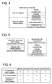
- the depiction commands, converted by the converting section 21 include such information representing kinds of objects, such as an image, characters, a figure and a gradation, and such other information representing kinds of image processing operations such as an overwrite processing, a ROP processing and a transparent overlay processing.
- depiction commands to which the depicting section 31 can apply the rendering are an image, characters, a figure, an overwrite processing and a ROP processing, and which are currently stored in the storage section 33 of the accelerator 3.
- the determining section 27 determines that the depicting section 31 of the accelerator 3 should apply the rendering to the depiction commands in regard to the image, the characters, the figure, the overwrite processing and the ROP processing, while the depicting section 22 of the control section 2 should apply the rendering to the other depiction commands in regard to the gradation, included in the information representing kinds of objects, and the transparent overlay processing.
- the processing section 28 adds the flag "0" to a corresponding portion of each of the depiction commands of the image, the characters, the figure, the overwrite processing and the ROP processing, while adds the flag "1" to a corresponding portion of each of the depiction commands of the gradation and the transparent overlay processing
- Step S6 determines whether or not the conversion processing for converting the PDL data to the depiction commands, which is to be implemented by the converting section 21, has been completed.
- Step S6 when determining that the conversion processing to be implemented by the converting section 21 has not been completed (Step S6: No), the processing section 28 makes the processing step return to Step S2.
- Step S6 when determining that the conversion processing to be implemented by the converting section 21 has been completed (Step S6: Yes), the processing section 28 reads the flag attached to the depiction command concerned (Step S7).
- the determining section 27 detennines whether the status of the flag above-read is "0" or "1" (Step S8).
- Step S8 when the determining section 27 determines that the status of the flag above-read is "0" (Step S8: Yes), the processing section 28 transmits an instruction signal to the depicting section 31 of the accelerator 3 so that the depicting section 31 implements the rendering operation based on the depiction command concerned (Step S9).
- Step S8 when the determining section 27 detennines that the status of the flag above-read is "1" (Step S8: No), the processing section 28 transmits an instruction signal to the depicting section 22 of the control section 2 so that the depicting section 22 implements the rendering operation based on the depiction command concerned (Step S 10).
- Step S9 or Step S10 the processing section 28 determines whether or not the depicting section 22 or 31 completes the rendering operation based on the depiction command concerned (Step S 11).
- Step S11 when determining that depicting section 22 or 31 has not completed the rendering operation based on the depiction command concerned (Step S 11; No), the processing section 28 makes the processing step return to Step S7.
- Step S11 when determining that depicting section 22 or 31 has completed the rendering operation based on the depiction command concerned (Step S11; Yes), the processing section 28 determines that the concerned rendering operation is finalized. Successively, the print data creating section 25 creates the print data based on the image data acquired by applying the rendering operation (Step S12), and then, based on the print data, the printer section 6 prints the image onto a recording medium, such as a paper sheet, etc., so as to output the printed recording medium (Step S 13).
- a recording medium such as a paper sheet, etc.
- the image forming operation is conducted according to the processing described in the foregoing.
- the converting section 21 parses the data written in the Page Description Language so as to convert it to the depiction commands. Further, the storage section 33 stores the information that relates to the depiction commands to which the depicting section 31 can apply the rendering operation, therein, and further, the reading section 26 reads out the information in regard to the depiction commands stored in the storage section 33. Successively, based on the information in regard to the depiction commands concerned, the determining section 27 determines whether the depicting section 31 or the depicting section 22 should implement the rendering operation in regard to the depiction commands concerned. Still successively, according to the determining result determined by the determining section 27, the processing section 28 makes either the depicting section 31 or the depicting section 22 implement the rendering operation in regard to the depiction commands concerned.
- the reading section 26 since the reading section 26 reads out the information in regard to the depiction commands from the storage section 33, it becomes possible to categorize the depiction commands to be processed by the rendering operation. In other words, it becomes possible to sort the depiction commands into a group of depiction commands to be processed by the depicting section 31 and another group of those to be processed by the depicting section 22, depending on the processing capability of the depicting section 31.
- the accelerator 3 makes the storage section 33 store only such depiction commands that are preferable for the accelerator 3 to efficiently implement the rendering operation.
- the determining section 27 can sort the depiction commands into the group to be processed by the depicting section 31 and the other group to be processed by the depicting section 22, it becomes unnecessary to update the software to be executed for implementing the sort processing, corresponding to the update of the accelerator 3, resulting in realization of an image forming apparatus having a highly flexible performance.
- processing section 28 creates the determining information in advance, it becomes unnecessary to determine whether the depicting section 22 or the depicting section 31 should implement rendering operation for every depiction command at the time of implementing the rendering operation. Accordingly, it becomes possible to hasten the implementation of the rendering operation.
- processing section 28 can generate a single batch of data including the determining information corresponding to each of the depiction commands by adding the determining information to the depiction commands, it becomes possible to make the data management operation easy.
- the accelerator as the hardware processing device, it becomes possible to alleviate the burden for processing other operations among the consecutive operations to be conducted by the image forming apparatus 1.
- the accelerator 3 is provided with the storage section 33, it becomes unnecessary to provide another storage device separately, resulted in reduction of the number of parts to be employed.
- any one of the depicting section 22 and the depicting section 31 can be selected as a currently suitable depicting section, depending on the kind of the object and the kind of the image processing, it becomes possible to implement the rendering operation with a high processing efficiency.
- the accelerator when the accelerator is changed to a high-functional accelerator as a new one, it would become possible for the high-functional accelerator to implement the rendering operations based on all of the depiction commands. In that case, as shown in Fig. 7 , the flag "0" is attached to all of the depiction commands. Accordingly, when the processing efficiency of the accelerator is updated, it is applicable that only the contents of data stored in the storage section provided in the accelerator are rewritten as needed.
- the flag "1" or "0" is attached to every depiction command depending on the result of determining whether the depicting section 22 or the depicting section 31 should implements the rendering operation, it is also applicable that the abovementioned determination is made in a unit of a page or a unit of a band, defined as a predetermined range of area. According to the above, since not only a number of flags, but also a number of times for implementing the abovementioned determining operations to be conducted at the time of the rendering, can be reduced, it becomes possible to hasten the image forming processing.
- each of the accelerators is made to store information in regard to its own efficiencies, such as a high functional capability, a standard capability, a cost reduction capability, etc., therein, while the control section stores the depiction commands, with which each of the accelerators can cope.
- the control section reads out depiction commands therefrom, and classifies the depiction commands above-read into a group of depiction commands to be processed by the depicting section provided in the control section and another group of depiction commands to be processed by the other depicting section provided in the accelerator, so as to make them implement the rendering operations, respectively.
- the result of determining a depiction command, to which the accelerator should apply the rendering operation varies depending on the circuit scale of the accelerator concerned.
- such a rendering operation that is simply performed in a unit of pixel and includes no arithmetic calculation process as performed for an image object can be regarded as a processing suitable for hardware, since it is easy to design the hardware concerned, and it is possible to not only minimize the scale of the circuit concerned, but also achieve the cost reduction.
- a high performance accelerator is employed in such a MFP (Multi-Functional Peripheral) model that requires a higher processing rate
- a low performance accelerator is employed in such another MFP (Multi-Functional Peripheral) model that requires a cost reduction of the system concerned. Accordingly, it becomes possible for the user to select a suitable MFP (Multi-Functional Peripherals), corresponding to the object and/or the rank desired by the user.
Landscapes
- Engineering & Computer Science (AREA)
- Physics & Mathematics (AREA)
- General Physics & Mathematics (AREA)
- Theoretical Computer Science (AREA)
- General Engineering & Computer Science (AREA)
- Record Information Processing For Printing (AREA)
- Facsimiles In General (AREA)
Abstract
Description
- The present invention relates to an image forming apparatus, an accelerator and an image forming method.
- There has been well-known an MFP (Multi-Functional Peripheral) that is provided with various kinds of functions, including a printing function, a copy function, a facsimile function, etc. The MFP is coupled to a plurality of computers through a network. Each of the users, who currently uses each of the computers, transmits data (Page Description Language), representing a document or the like created by using the computer concerned, to the MFP through the network. Receiving the Page Description Language, the MFP parses the Page Description Language concerned so as to create a depiction command, and then, conducts rendering (image depiction processing) based on the depiction command above-created, so as to output a printed paper sheet onto which a formed image is fixed.
- Rendering can be implemented by processing hardware and/or processing software, both provided in the MFP concerned. For instance, conventionally well-known is such a printing apparatus that is provided with a plurality of image depicting sections, each of which performs an image depicting operation by using the processing hardware, and another plurality of image depicting sections, each of which performs an image depicting operation by using the processing software, and that makes the both kinds of image depicting sections implement the image depiction processing in parallel so as to improve the processing velocity faster than ever (for instance, set forth in Patent Document 1).
- The printing apparatus, set forth in
Patent Document 1, sorts the processing into the processing hardware and the processing software, while detecting the loading status of the processing software. On an occasion of sorting the processing, the printing apparatus gives a priority to the processing hardware so as to make the high-speed depiction processing possible. Accordingly, it becomes possible to shorten the process time to be consumed before the printing operation is actually started, resulting in an improvement of the printing velocity. - Further, still conventionally well-known is such a print controlling apparatus that is provided with a rendering section, which performs rendering by using the processing hardware, and another rendering section, which performs rendering by using the processing software, and that categorizes the depiction commands into those to be processed by the processing hardware and others to be processed by the processing software, so as to implement the processing of each of the depiction commands, corresponding to the level of the depiction command concerned (for instance, set forth in Patent Document 2).
- In the print controlling apparatus set forth in
Patent Document 2, a high-quality rendering operation is performed by the processing hardware, and accordingly, the processing software, serving as a subsidiary function of the processing hardware, does not perform such a high-quality rendering operation that is equivalent to that to be performed by the processing hardware. -
- Patent Document 1: Tokkai
2009-269179 - Patent Document 2:
JP-2875725 - However, in order to allot a processing to either the processing hardware or the processing software while referring to the loading statuses of them as described in
Patent Document 1, it is necessary to configure the system so that both the processing hardware and the processing software can process the same object. In other words, if neither the processing hardware nor the processing software has the ability of processing all of the objects to be instructed by the depiction commands, the processing would be delayed and stuck. Further, there has been such a problem that, in order to make all of the objects processable, a large scale electric circuit should be provided for the processing hardware, resulting in the steep rise of the manufacturing cost thereof. - Further, in order to categorize the processing, corresponding to the level of the depiction command concerned, as described in
Patent Document 2, it is necessary to determine in advance those to be processed by the processing hardware and others to be processed by the processing software. As a result, the flexibility of the system concerned has been lost, and it has been virtually impossible to easily replace the processing hardware to an updated one. In addition, there has been such a problem that it is also necessary to update the software to be executed for allotting the processing, corresponding to the processing hardware to be employed, resulting in the steep rise of the updating cost thereof. - Accordingly, the present invention is achieved to overcome the abovementioned problems. One of objects of the present invention is to provide an image forming apparatus, an accelerator and an image forming method, each of which makes it possible to suppress the scale enlargement of the electric circuit to be employed for the processing hardware, makes it unnecessary to update the processing software for allotting the processing, corresponding to the change of the processing hardware, and makes the system highly flexible.
- The invention recited in
Claim 1 is characterized in that, in an image forming apparatus that applies rendering operation to depiction commands acquired by parsing data written in a Page Description Language, the image forming apparatus is provided with: - converting means for parsing inputted data written in the Page Description Language and converting to the depiction commands;
- first rendering means for applying the rendering operation to the depiction commands by hardware processing means;
- second rendering means for applying the rendering operation to the depiction commands by software processing means;
- storing means for storing information in regard to depiction commands to which the rendering operation is can be applied by the first rendering means;
- reading means for reading the information in regard to the depiction commands stored in the storing means;
- determining means for determining whether the first rendering means or the second rendering means should apply the rendering operation to the depiction command, based on the information in regard to the depiction commands, read by the reading means; and
- controlling means for making the rendering means, determined by the detennining means, apply the rendering operation to the depiction command.
- The invention recited in
Claim 2 is characterized in that, in the image forming apparatus recited inClaim 1, the image forming apparatus is further provided with: - creating means for creating determining information representing a result of whether the first rendering means or the second rendering means should apply the rendering operation to the depiction command, and
- based on the determining information created by the creating means, the controlling means makes any one of the first rendering means and the second rendering means implement the rendering operation.
- The invention recited in
Claim 3 is characterized in that, in the image forming apparatus recited inClaim 2, the image forming apparatus is further provided with: - adding means for adding the determining information, created by the creating means, to the depiction command.
- The invention recited in
Claim 4 is characterized in that, in the image forming apparatus recited in any one of Claims 1-3, the hardware processing means is provided with the storing means. - The invention recited in
Claim 5 is characterized in that, in the image forming apparatus recited in any one of Claims 1-4, the information in regard to the depiction commands varies depending on a processing capability of the hardware processing means. - The invention recited in
Claim 6 is characterized in that, in the image forming apparatus recited in any one of Claims 1-5, the information in regard to the depiction commands includes information in regard to kinds of objects. - The invention recited in
Claim 7 is characterized in that, in the image forming apparatus recited inClaim 6, the information in regard to the kinds of the objects includes an image, a character, a figure and a gradation. - The invention recited in
Claim 8 is characterized in that, in the image forming apparatus recited in any one of Claims 1-7, the information in regard to the depiction commands includes information in regard to kinds of image processing operations. - The invention recited in Claim 9 is characterized in that, in the image forming apparatus recited in
Claim 8, the information in regard to the kinds of the image processing operations includes an overwrite processing, a ROP processing and a transparent overlay processing. - The invention recited in
Claim 10 is characterized in that, in the image forming apparatus recited in any one of Claim 1-9, the determining means determines whether the first rendering means or the second rendering means should implement the rendering operation in a unit of a page or in a unit of a band. - The invention recited in Claim 11 is characterized in that, in an accelerator that is employed as hardware processing means to apply rendering operation to depiction commands so as to form an image, the accelerator is provided with:
- storing means to store information in regard to depiction commands to which the accelerator itself can apply the rendering operation.
- The invention recited in Claim 11 is characterized in that, in an image forming method for forming an image by employing an image forming apparatus that stores information in regard to depiction commands to which a rendering operation can be applied by using hardware processing means, and by applying the rendering operation to the depiction commands, acquired by parsing data written in a Page Description Language, by means of the hardware processing means or software processing means, the image forming method comprises the steps of:
- parsing input data written in the Page Description Language so as to convert the input data to depiction commands;
- reading information, in regard to the depiction commands;
- determining whether the hardware processing means or the software processing means should apply the rendering operation to the depiction commands, based on the depiction commands read in the reading step; and
- applying the rendering operation to the depiction commands by means of the processing means determined in the determining step.
- According to the invention recited in
Claim 1, the converting means parses the input data written in the Page Description Language so as to convert the input data to the depiction commands. Further, the storing means stores the information that relates to the depiction commands to which the first rendering means can apply the rendering operation, therein, and further, the reading means reads out the information in regard to the depiction commands stored in the storing means. Successively, based on the information in regard to the depiction commands concerned, the determining means determines whether the first rendering means or the second rendering means should implement the rendering operation in regard to the depiction commands concerned. Still successively, according to the determining result determined by the determining means, the control means makes either the first rendering means or the second rendering means implement the rendering operation in regard to the depiction commands concerned. - According to the abovementioned process, since the reading means reads out the information in regard to the depiction commands from the storing means, it becomes possible to categorize the depiction commands to be processed by the rendering operation. In other words, it becomes possible to sort the depiction commands into a group of depiction commands to be processed by the first rendering means and another group of those to be processed by the second rendering means, depending on the processing capability of the first rendering means.
- Accordingly, it becomes unnecessary to configure the system so as to make both the first rendering means and the second rendering means possible to process the same object, and as a result, it becomes possible to suppress the circuit scale expansion of the hardware processing means for making the first rendering means perform the rendering operation. Therefore, it becomes applicable that the hardware processing means makes the storing means store only such depiction commands that are preferable for the hardware processing means to efficiently implement the rendering operation.
- Further, even when the information in regard to the depiction commands, stored in the storing means, is updated, since the determining means can sort the depiction commands into the group to be processed by the first rendering means and the other group to be processed by the second rendering means, it becomes unnecessary to update the software to be executed for implementing the sort processing, corresponding to the update of the hardware processing means, resulting in realization of an image forming apparatus having a highly flexible performance. In other words, it becomes unnecessary to fix the group of depiction commands to be processed for implementing the rendering operation by the hardware processing means and the other group of depiction commands to be processed for implementing the rendering operation by the software processing means, but it becomes possible to update each of the groups concerned in a flexible way.
- According to the invention recited in
Claim 2, by making the creating means create the determining information in advance, it becomes unnecessary to determine whether the first rendering means or the second rendering means should implement rendering operation for every depiction command at the time of implementing the rendering operation. - Accordingly, it becomes possible to hasten the implementation of the rendering operation.
- According to the invention recited in
Claim 3, since the adding means can generate a single batch of data including the determining information corresponding to each of the depiction commands by adding the determining information to the depiction commands, it becomes possible to make the data management operation easy. - According to the invention recited in
Claim 4, by making the accelerator provided with the storing means, it becomes unnecessary to provide another storing means separately, resulting in reduction of the number of parts to be employed. - According to the invention recited in
Claim 5, since the information in regard to the depiction commands varies depending on the processing capability of the hardware processing means, it becomes possible to implement the rendering operation with a high processing efficiency. - According to the invention recited in
Claims - According to the invention recited in
Claims 8, 9, since any one of the first rendering means or the second rendering means can be selected as a currently suitable depicting section, depending on the kind of the image processing, it becomes possible to implement the rendering operation with a high processing efficiency. - According to the invention recited in
Claim 10, since it becomes possible to determine whether the first rendering means or the second rendering means should implement the rendering operation in a unit of a page or in a unit of a band, it becomes possible to hasten the processing for implementing the image forming operation. - According to the invention recited in Claim 11, by employing an accelerator as the hardware processing means, it becomes possible to alleviate the burden for implementing other processing in the consecutive processing to be conducted by the image forming apparatus.
- Further, by providing the storing means into the accelerator, it becomes unnecessary to provide another storing means separately, resulting in reduction of the number of parts to be employed.
- According to the invention recited in Claim 12, the image forming apparatus parses the input data written in the Page Description Language so as to convert the input data to the depiction commands. The image forming apparatus stores the information in regard to depiction commands to which the rendering operation can be applied by using the hardware processing means, and reads the information in regard to depiction commands stored therein. Based on the information above-read in regard to depiction commands, the image forming apparatus determines whether the hardware processing means or the software processing means should apply the rendering operation to the depiction commands. Then, the image forming apparatus makes the determined processing means apply the rendering operation to the depiction commands.
- According to the abovementioned process, by reading out the information in regard to the depiction commands, it becomes possible to categorize the depiction commands to be processed by the rendering operation. In other words, it becomes possible to sort the depiction commands into a group of depiction commands to be processed by the hardware processing means and another group of those to be processed by the software processing means, depending on the processing capability of the hardware processing means.
- Accordingly, it becomes unnecessary to configure the system so as to make both the hardware processing means and the software processing means possible to process the same object, and as a result, it becomes possible to suppress the circuit scale expansion of the hardware processing means for making the first rendering means perform the rendering operation. Therefore, it becomes applicable that the hardware processing means makes the storing means store only such depiction commands that are preferable for the hardware processing means to efficiently implement the rendering operation.
- Further, even when the information in regard to the depiction commands, stored in the storing means, is updated, since the determining means can sort the depiction commands into the group to be processed by the hardware processing means and the other group to be processed by the software processing means, it becomes unnecessary to update the software to be executed for implementing the sort processing, corresponding to the update of the hardware processing means, resulting in realization of an image forming apparatus having a highly flexible performance. In other words, it becomes unnecessary to fix the group of depiction commands to be processed for implementing the rendering operation by the hardware processing means and the other group of depiction commands to be processed for implementing the rendering operation by the software processing means, but it becomes possible to update each of the groups concerned in a flexible way.
-
-
Fig. 1 is a block diagram indicating a brief configuration of an image forming system. -
Fig. 2 is a block diagram indicating a brief configuration of a control section and an accelerator. -
Fig. 3 is a flowchart indicating image forming processing to be conducted by an image forming apparatus. -
Fig. 4 is a drawing for explaining a depiction command. -
Fig. 5 is a drawing for explaining depiction commands to which depicting sections apply rendering operation, respectively. -
Fig. 6 is a drawing for explaining flags to be attached to depiction commands. -
Fig. 7 is a drawing for explaining flags to be attached to depiction commands, when a high performance accelerator is employed. - Referring to the drawings, an image forming apparatus, an accelerator and an image forming method, each embodied in the present invention, will be detailed in the following.
- As shown in
Fig. 1 , animage forming apparatus 1 serves as an MFP (Multi-Functional Peripherals) that is provided with a scanner function, a copy function and a printer function. Theimage forming apparatus 1 is coupled to a network N through ahub 10. Further, theimage forming apparatus 1 is coupled to a plurality of user terminal devices P through the network N. Concretely speaking, theimage forming apparatus 1 receives PDL data (data written in the Page Description Language to be used for an image forming operation), and implements the rendering operation (image depiction processing) based on the depiction command acquired by parsing the PDL data above-received, so as to create image data representing an image to be printed. - As shown in
Fig. 1 , theimage forming apparatus 1 is constituted by acontrol section 2, anaccelerator 3, an input/output interface 4, ascanner section 5, aprinter section 6, an ADF (Automatic Document Feeder)section 7 and anoperation display section 8. - The
control section 2 is provided with a CPU (Central Processing Unit), a ROM (Read Only Memory), a RAM (Random Access Memory), a storage section, etc., which are conventionally well-known. - As shown in
Fig. 1 andFig. 2 , thecontrol section 2 receives PDL data (written in the Page Description Language) to be used for the printing operation, from one of the user terminal devices P coupled to the network N, through the input/output interface 4. Thecontrol section 2 transmits print data, created from the PDL data, to theprinter section 6. - The
control section 2 is coupled to theaccelerator 3. - The
control section 2 is provided with a convertingsection 21, a depictingsection 22, an expandingsection 23, anon-reversible compressing section 24, a printdata creating section 25, areading section 26, a determiningsection 27, aprocessing section 28 and acommunication section 29. - The converting
section 21 parses the PDL data received from thehub 10 so as to convert the PDL data to the depiction commands. In other words, the convertingsection 21 serves as a converting measure. In this connection, the depiction commands are such information that is necessary for the depictingsection 22 or another depictingsection 31, detailed later, to develop them to image data, and includes, for instance, kinds of objects (an image, a character, a figure, a gradation, etc.), sizes, colors, shapes, positional coordinate values, complication degrees of processing (number of arithmetic calculations to be repeated, etc.), kinds of image processing (an overwrite processing, an ROP processing, a permeabilize processing, etc.), units of rendering operations (for instance, in a unit of page, in a unit of band, in a unit of depiction command, etc.), etc. - The depicting
section 22 makes thecontrol section 2, serving as processing software measure, apply the rendering to the depiction commands converted by the convertingsection 21. Concretely speaking, the CPU (Central Processing Unit) included in thecontrol section 2 executes the software in regard to the rendering operation so as to implement the rendering. In other words, the depictingsection 22 serves as a second rendering measure. - The expanding
section 23 expands the image data compressed by theaccelerator 3. - The
non-reversible compressing section 24 applies a non-reversible compression processing to image data as a pre-stage processing to be conducted before the image data is converted to the print data. - The print
data creating section 25 creates print data to be transmitted to theprinter section 6. - The
reading section 26 reads the information in regard to the depiction commands stored into a storage section 33 provided in theaccelerator 3. In other words, thereading section 26 serves as a reading measure. In this connection, in addition to the information in regard to the depiction commands abovementioned, the information in regard to the depiction commands also includes such information that relates to the processing ability of the accelerator 3 (such as a high speed processing, a low speed processing, etc.). The information in regard to the processing ability of theaccelerator 3 serves as an indicator for determining which depiction command is to be rendering-processed by theaccelerator 3. - Based on the information in regard to the depiction commands read by the
reading section 26, the determiningsection 27 determines whether the depictingsection 22 of thecontrol section 2 or the depicting section 33 of theaccelerator 3 should implement the rendering operation in regard to the concerned depiction command. - The
processing section 28 conducts controlling operations of each of the sections included in thecontrol section 2. - The
processing section 28 transmits a command signal to any one of the depictingsection 22 and the depictingsection 31, determined by the determiningsection 27, so as to apply the rendering operation to the depiction command concerned. In other words, theprocessing section 28 serves as a controlling measure. - Based on the judgment determined by the determining
section 27, theprocessing section 28 creates judgment information representing the determination whether the depictingsection 22 of thecontrol section 2 or the depicting section 33 of theaccelerator 3 should implement the rendering operation in regard to the concerned depiction command. In other words, theprocessing section 28 serves as a creating measure. - The
processing section 28 adds the judgment information, above-created, to the depiction command, currently converted by the convertingsection 21. In other words, theprocessing section 28 serves as an adding measure. Concretely speaking, theprocessing section 28 flags "0" onto the depiction command to be processed by the depictingsection 31, while flags "1" onto the other depiction command to be processed by the depictingsection 22. By adding the judgment information to the depiction command as abovementioned, it becomes possible for the determiningsection 27 to easily determine whether the depictingsection 22 or the depicting section 33 should implement the rendering operation in regard to the depiction command concerned, based on the flag serving as the judgment information. - The
communication section 29 is coupled to both thehub 10 and theaccelerator 3. - The
communication section 29 receives the PDL data sent from thehub 10. - The
communication section 29 transmits the depiction command, currently converted by the convertingsection 21, to theaccelerator 3, so as to make the depictingsection 31 apply the rendering operation to the depiction command concerned. - The
communication section 29 receives the image data, created by applying the rendering operation, from theaccelerator 3. - The
communication section 29 transmits print data, created by the printdata creating section 25, to theprinter section 6. - The
control section 2 reads out various kinds of processing programs, such as system programs, image forming/processing programs, paper-sheet ejection processing programs, etc., stored in the ROM (Read Only Memory), and develops them into the RAM (Random Access Memory), so as to implement the centralized controlling operations for controlling each of the sections included in theimage forming apparatus 1 according to the programs currently developed in the RAM. Further, the storage section stores information in regard to preview images to be created and employed for displaying various kinds of setting information established by the user's inputting operations performed through theoperation display section 8, therein. - For instance, the CPU (Central Processing Unit) creates a job based on the data (image information) inputted from the
scanner section 5 and the setting information inputted through theoperation display section 8. Then, the CPU implements the job concerned so as to form an image onto the paper sheet. - In this connection, hereinafter, the term of "job" is defined as a series of consecutive operations in respect to a unit image forming task. For instance, when the user intends to make a copy from a document constituted by plural paper sheets, the series of consecutive operations in respect to the copying task for making a single copy of the document constituted by the plural paper sheets is a job above-defined. On the other hand, when the user intends to make a plurality of copies from a document constituted by plural paper sheets, the series of consecutive operations in respect to the copying task for making the plurality of copies of the document constituted by the plural paper sheets is a job above-defined.
- As shown in
Fig. 1 andFig. 2 , theaccelerator 3 is coupled to thecontrol section 2. - The
accelerator 3 is provided with the depictingsection 31, a compressingsection 32, the storage section 33, aprocessing section 34 and acommunication section 35. - The depicting
section 31 makes the processing hardware measure apply the rendering to the depiction commands converted by the convertingsection 21. Concretely speaking, theaccelerator 3, serving as the processing hardware measure, implements the rendering. In other words, the depictingsection 31 serves as a first rendering measure. - Before transmitting the image data, generated by applying the rendering operation, to the
control section 2, the compressingsection 32 applies a compression processing to the image data concerned. Various kinds of compression methods are available, and an optimum compression method is selected from the compression methods above-provided, corresponding to the capacity of the image data concerned and the presence or absence of the re-rendering operation. - The storage section 33 stores information that relates to the depiction commands to which the depicting
section 31 of theaccelerator 3 can apply the rendering operation, therein. In other words, the storage section 33 serves as a storage measure. As described in the above, since the storage section 33 stores only such the information that relates to the depiction commands to which the depictingsection 31 of theaccelerator 3 can apply the rendering operation, therein, the depictingsection 22 of thecontrol section 2 applies the rendering operation to all of the depiction commands that are not stored in the storage section 33. - The
processing section 34 conducts controlling operations for controlling each of the sections included in theaccelerator 3. - The
communication section 35 is coupled to thecontrol section 2. - The
communication section 35 receives the depiction commands converted by the convertingsection 21 of thecontrol section 2. - The
communication section 35 transmits the image data, generated by applying the rendering operation in the depictingsection 31, to thecontrol section 2. - The input/
output interface 4 serves as an interface to couple thecontrol section 2 to various kinds of external input/output apparatuses, and is coupled to thehub 10 and thecontrol section 2. - The input/
output interface 4 receives the PDL data sent from each of the plurality of user terminal devices P (such as a personal computer, etc.), and then, transmits the PDL data above-received to thecontrol section 2. - As shown in
Fig. 1 , thescanner section 5 is provided with an image sensor, such as a CCD (Charge Coupled Device), etc., and a scanner controlling section. Based on the controlling signals sent from thecontrol section 2, the scanner controlling section controls the driving operations to be performed in each of the sections provided in thescanner section 5. Concretely speaking, the scanner controlling section controls the implementation of the exposure scanning operation for scanning a light beam onto the document, which is currently placed onto the contact glass (platen glass), so as to read an image from the reflected light projected onto the image sensor. Successively, the scanner controlling section controls the opt-electric converting actions, so as to convert intensities of the reflected light projected onto the image sensor to analogue image signals, and then, transmits the analogue image signals to thecontrol section 2. - As shown in
Fig. 1 , theprinter section 6 is provided with an LD (Laser Diode) section and a printer controlling section. Theprinter section 6 forms an image onto a paper sheet, based on the image data inputted from thecontrol section 2. In this connection, when the image data is transmitted from one of the plurality of user terminal devices P to theimage forming apparatus 1, theprinter section 6 forms the image based on data received from thecontrol section 2. - The LD section is provided with an LD (Laser Diode), a photoreceptor drum, an electric charging section, an exposing section, a developing section, a transferring section, a cleaning section, a fixing section, etc. In addition, the LD section is also provided with such a conveyance section that includes pairs of paper-sheet feeding rollers to convey the paper sheet along an inner conveyance path, a pair of registration rollers, various kinds of rollers including a pair of paper-sheet ejection rollers, a conveyance path switchover plate, a conveyance direction reversing section, etc. Under the controlling actions conducted by the printer controlling section, the conveyance section of the LD section picks up a paper sheet, designated in regard to the job concerned, from the paper sheet feeding tray, so as to feed it into the conveyance path, and conveys the paper sheet through the conveyance path. A plurality of sensors is disposed along the conveyance path of the LD section. Each of the plurality of sensors generates a detection signal every time when the paper sheet passes through it, and outputs the detection signal to the printer controlling section.
- Receiving the controlling signals sent from the
control section 2, the printer controlling section controls the operations to be implemented in each of the sections included in the LD section. Further, based on the detection signals detected by the plurality of sensors respectively disposed at various positions located along the conveyance path, the printer controlling section counts a number of paper sheets fed during every job implementation, so as to output the counted number to thecontrol section 2. - Based on the instructions received from the printer controlling section, the
printer section 6 makes the electric charging section electrically charge the circumferential surface of the photoreceptor drum, and then, based on the PWM (Pulse Width Modulation) signals inputted from thecontrol section 2, makes the LD irradiate a laser beam onto the circumferential surface of the photoreceptor drum so as to form an electrostatic latent image thereon. Successively, theprinter section 6 makes the developing section adhere toner onto the area including the electrostatic latent image formed on the circumferential surface of the photoreceptor drum so as to form a visible toner image thereon, and then, makes the transferring section transfer the visible toner image onto the paper sheet so as to form an image thereon. Still successively, theprinter section 6 makes the fixing section fix the image above-transferred onto the paper sheet concerned, and then, makes the pair of paper-sheet ejection rollers convey the paper sheet, on which the image is already formed, to a post processing section. - As shown in
Fig. 1 , theADF section 7 is provided with an ADF (Automatic Document Feeder) controlling section that conducts the operations for controlling theADF section 7. TheADF section 7 automatically conveys a single document paper sheet or a plurality of document paper sheets, placed on a document placing tray (not shown in the drawings), onto the contact glass of thescanner section 5, one by one. - As shown in
Fig. 1 , theoperation display section 8 is provided with a displaying section, an operation display controlling section, an operating section and a group of operation keys (not shown in the drawings). - According to the display controlling signals received from the operation display controlling section, the displaying section displays various kinds of setting screens, a status of current image, an operating status of each of various functions, etc., thereon. Further, an operating section that is provided with, for instance, a pressure-sensitive (resistance film pressure-sensitive type) touch panel in which transparent electrodes are arranged in a lattice pattern, etc., is mounted over the display surface of the displaying section, so as to detect X-Y coordinate electric values representing a pressure point depressed by a finger, a touch pen or the like, and the displaying section output the positional signals, above-detected, to the operation display controlling section as the operational signals.
- Next, an image forming method to be implemented by the
image forming apparatus 1 will be detailed in the following. - The
image forming apparatus 1 commences the image forming operation at the time when thecontrol section 2 receives PDL data from one of the user terminal devices P through thecommunication section 29. - As indicated in the flowchart shown in
Fig. 3 , at the time when thecontrol section 2 receives the PDL data, thereading section 26 accesses the storage section 33 of theaccelerator 3 so as to read out information in regard to the depiction commands concerned, therefrom (Step S 1). - Successively, the converting
section 21 parses the PDL data above-received so as to convert the PDL data to the depiction commands (Step S2). - Still successively, based on the information read out from the storage section 33, the determining
section 27 determines whether or not the rendering can be applied to each of the depiction commands above-converted in the depictingsection 31 of the accelerator 3 (Step S3). - Still successively, when the determining
section 27 determines that the rendering can be applied to one of the depiction commands in the depictingsection 31 of the accelerator 3 (Step S3: Yes), theprocessing section 28 adds a flag "0" (determination information), indicating that the rendering operation is to be implemented in the depictingsection 31, to concerned one of the depiction commands (Step S4). - Still successively, when the determining
section 27 determines that the rendering cannot be applied to one of the depiction commands in the depictingsection 31 of the accelerator 3 (Step S3: No), theprocessing section 28 adds a flag "1" (determination information), indicating that the rendering operation is to be implemented in the depictingsection 22, to concerned one of the depiction commands (Step S5). - In this connection, in regard to the processing from the operation for determining the depicting section, which actually applies the rendering to the depiction command concerned, to the operation for adding the flag, a concrete example will be cited and detailed in the following.
- For instance, as indicated in the table shown in
Fig. 4 , it is assumed that the depiction commands, converted by the convertingsection 21, include such information representing kinds of objects, such as an image, characters, a figure and a gradation, and such other information representing kinds of image processing operations such as an overwrite processing, a ROP processing and a transparent overlay processing. - Further, it is also assumed that the depiction commands to which the depicting
section 31 can apply the rendering are an image, characters, a figure, an overwrite processing and a ROP processing, and which are currently stored in the storage section 33 of theaccelerator 3. - In the above-assumed case, as indicated in the table shown in
Fig. 5 , the determiningsection 27 determines that the depictingsection 31 of theaccelerator 3 should apply the rendering to the depiction commands in regard to the image, the characters, the figure, the overwrite processing and the ROP processing, while the depictingsection 22 of thecontrol section 2 should apply the rendering to the other depiction commands in regard to the gradation, included in the information representing kinds of objects, and the transparent overlay processing. - Successively, as indicated in the table shown in
Fig. 6 , theprocessing section 28 adds the flag "0" to a corresponding portion of each of the depiction commands of the image, the characters, the figure, the overwrite processing and the ROP processing, while adds the flag "1" to a corresponding portion of each of the depiction commands of the gradation and the transparent overlay processing - Returning to the flowchart shown in
Fig. 3 , after the processing to be implemented in Step S4 or S5 is completed, theprocessing section 28 determines whether or not the conversion processing for converting the PDL data to the depiction commands, which is to be implemented by the convertingsection 21, has been completed (Step S6). - In Step S6, when determining that the conversion processing to be implemented by the converting
section 21 has not been completed (Step S6: No), theprocessing section 28 makes the processing step return to Step S2. - In Step S6, when determining that the conversion processing to be implemented by the converting
section 21 has been completed (Step S6: Yes), theprocessing section 28 reads the flag attached to the depiction command concerned (Step S7). - Successively, the determining
section 27 detennines whether the status of the flag above-read is "0" or "1" (Step S8). - Still successively, when the determining
section 27 determines that the status of the flag above-read is "0" (Step S8: Yes), theprocessing section 28 transmits an instruction signal to the depictingsection 31 of theaccelerator 3 so that the depictingsection 31 implements the rendering operation based on the depiction command concerned (Step S9). - On the other hand, when the determining
section 27 detennines that the status of the flag above-read is "1" (Step S8: No), theprocessing section 28 transmits an instruction signal to the depictingsection 22 of thecontrol section 2 so that the depictingsection 22 implements the rendering operation based on the depiction command concerned (Step S 10). - After the rendering operation has implemented in Step S9 or Step S10, the
processing section 28 determines whether or not the depictingsection - In Step S11, when determining that depicting
section processing section 28 makes the processing step return to Step S7. - In Step S11, when determining that depicting
section processing section 28 determines that the concerned rendering operation is finalized. Successively, the printdata creating section 25 creates the print data based on the image data acquired by applying the rendering operation (Step S12), and then, based on the print data, theprinter section 6 prints the image onto a recording medium, such as a paper sheet, etc., so as to output the printed recording medium (Step S 13). - The image forming operation is conducted according to the processing described in the foregoing.
- According to the
image forming apparatus 1 described in the foregoing, the convertingsection 21 parses the data written in the Page Description Language so as to convert it to the depiction commands. Further, the storage section 33 stores the information that relates to the depiction commands to which the depictingsection 31 can apply the rendering operation, therein, and further, thereading section 26 reads out the information in regard to the depiction commands stored in the storage section 33. Successively, based on the information in regard to the depiction commands concerned, the determiningsection 27 determines whether the depictingsection 31 or the depictingsection 22 should implement the rendering operation in regard to the depiction commands concerned. Still successively, according to the determining result determined by the determiningsection 27, theprocessing section 28 makes either the depictingsection 31 or the depictingsection 22 implement the rendering operation in regard to the depiction commands concerned. - According to the abovementioned process, since the
reading section 26 reads out the information in regard to the depiction commands from the storage section 33, it becomes possible to categorize the depiction commands to be processed by the rendering operation. In other words, it becomes possible to sort the depiction commands into a group of depiction commands to be processed by the depictingsection 31 and another group of those to be processed by the depictingsection 22, depending on the processing capability of the depictingsection 31. - Accordingly, it becomes unnecessary to configure the system so as to make both the depicting
section 31 and the depictingsection 22 possible to process the same object, and as a result, it becomes possible to suppress the circuit scale expansion of theaccelerator 3 for making the depictingsection 31 perform the rendering operation. Therefore, it becomes applicable that theaccelerator 3 makes the storage section 33 store only such depiction commands that are preferable for theaccelerator 3 to efficiently implement the rendering operation. - Further, even when the information in regard to the depiction commands, stored in the storage section 33, is updated, since the determining
section 27 can sort the depiction commands into the group to be processed by the depictingsection 31 and the other group to be processed by the depictingsection 22, it becomes unnecessary to update the software to be executed for implementing the sort processing, corresponding to the update of theaccelerator 3, resulting in realization of an image forming apparatus having a highly flexible performance. In other words, it becomes unnecessary to fix the group of depiction commands to be processed for implementing the rendering operation by theaccelerator 3, serving as the hardware, and the other group of depiction commands to be processed for implementing the rendering operation by executing the software in the CPU, but it becomes possible to update each of the groups concerned in a flexible way. - Further, by making the
processing section 28 create the determining information in advance, it becomes unnecessary to determine whether the depictingsection 22 or the depictingsection 31 should implement rendering operation for every depiction command at the time of implementing the rendering operation. Accordingly, it becomes possible to hasten the implementation of the rendering operation. - Still further, since the
processing section 28 can generate a single batch of data including the determining information corresponding to each of the depiction commands by adding the determining information to the depiction commands, it becomes possible to make the data management operation easy. - Still further, by employing the accelerator as the hardware processing device, it becomes possible to alleviate the burden for processing other operations among the consecutive operations to be conducted by the
image forming apparatus 1. - Still further, since the
accelerator 3 is provided with the storage section 33, it becomes unnecessary to provide another storage device separately, resulted in reduction of the number of parts to be employed. - Yet further, since any one of the depicting
section 22 and the depictingsection 31 can be selected as a currently suitable depicting section, depending on the kind of the object and the kind of the image processing, it becomes possible to implement the rendering operation with a high processing efficiency. - Incidentally, the scope of the present invention is not limited to the embodiment described in the foregoing. Modifications and additions, made by a skilled person without departing from the spirit and scope of the invention, shall be included in the scope of the present invention.
- For instance, when the accelerator is changed to a high-functional accelerator as a new one, it would become possible for the high-functional accelerator to implement the rendering operations based on all of the depiction commands. In that case, as shown in
Fig. 7 , the flag "0" is attached to all of the depiction commands. Accordingly, when the processing efficiency of the accelerator is updated, it is applicable that only the contents of data stored in the storage section provided in the accelerator are rewritten as needed. - According to the abovementioned, since the information in regard to the depiction commands differs corresponding to the processing efficiency of the accelerator, it becomes possible to implement the rendering operation with a high processing efficiency.
- Further, although, in the embodiment described in the foregoing, the flag "1" or "0" is attached to every depiction command depending on the result of determining whether the depicting
section 22 or the depictingsection 31 should implements the rendering operation, it is also applicable that the abovementioned determination is made in a unit of a page or a unit of a band, defined as a predetermined range of area. According to the above, since not only a number of flags, but also a number of times for implementing the abovementioned determining operations to be conducted at the time of the rendering, can be reduced, it becomes possible to hasten the image forming processing. - Still further, although, in the embodiment described in the foregoing, the information in regard to the depiction commands to which the accelerator applies the rendering operation is stored in the storage section, it is also applicable that each of the accelerators is made to store information in regard to its own efficiencies, such as a high functional capability, a standard capability, a cost reduction capability, etc., therein, while the control section stores the depiction commands, with which each of the accelerators can cope. In this case, after accessing each of the accelerators so as to determine the efficiencies of each of the accelerators, the control section reads out depiction commands therefrom, and classifies the depiction commands above-read into a group of depiction commands to be processed by the depicting section provided in the control section and another group of depiction commands to be processed by the other depicting section provided in the accelerator, so as to make them implement the rendering operations, respectively.
- Yet further, the result of determining a depiction command, to which the accelerator should apply the rendering operation, varies depending on the circuit scale of the accelerator concerned.
- For instance, such a rendering operation that is simply performed in a unit of pixel and includes no arithmetic calculation process as performed for an image object can be regarded as a processing suitable for hardware, since it is easy to design the hardware concerned, and it is possible to not only minimize the scale of the circuit concerned, but also achieve the cost reduction.
- On the other hand, such another rendering operation that requires a lot of arithmetic calculations for the electronic transparent overlay processing, etc., can be regarded as a processing suitable for software, since, if hardware were employed for this purpose, the scale of the hardware concerned would be enlarged and the manufacturing cost would be skyrocketed.
- Therefore, it is applicable that, if it is desired to employ such an accelerator that is manufactured at a low cost, such the accelerator that can cope with only the image object is selected, while, if it is desired to employ such an accelerator in which its efficiency weighs heavily, such the accelerator that can also cope with the rendering operation requiring a lot of arithmetic calculations for the electronic transparent overlay processing, etc., is selected.
- Generally speaking, since the rendering operation can be performed at a higher processing rate by employing hardware, rather than by employing software, a high performance accelerator is employed in such a MFP (Multi-Functional Peripheral) model that requires a higher processing rate, while, a low performance accelerator is employed in such another MFP (Multi-Functional Peripheral) model that requires a cost reduction of the system concerned. Accordingly, it becomes possible for the user to select a suitable MFP (Multi-Functional Peripherals), corresponding to the object and/or the rank desired by the user.
-
- 1
- an image forming apparatus
- 2
- a control section (software processing means)
- 3
- an accelerator (hardware processing means)
- 21
- a converting section (converting means)
- 22
- a depicting section (second rendering means)
- 26
- a reading section (reading means)
- 27
- a determining section (determining means)
- 28
- a processing section (controlling means, creating means, adding means)
- 31
- a depicting section (first rendering means)
- 33
- a storage section (storing means)
Claims (12)
- An image forming apparatus that applies rendering operation to depiction commands acquired by parsing data written in a Page Description Language, characterized in that the image forming apparatus is provided with:converting means for parsing inputted data written in the Page Description Language and converting to the depiction commands;first rendering means for applying the rendering operation to the depiction commands by hardware processing means;second rendering means for applying the rendering operation to the depiction commands by software processing means;storing means for storing information in regard to depiction commands to which the rendering operation can be applied by the first rendering means;reading means for reading the information in regard to the depiction commands stored in the storing means;determining means for determining whether the first rendering means or the second rendering means should apply the rendering operation to the depiction command, based on the information in regard to the depiction commands, read by the reading means; andcontrolling means for making the rendering means, determined by the determining means, apply the rendering operation to the depiction command.
- The image forming apparatus recited in Claim 1, characterized in that the image forming apparatus is further provided with:creating means for creating determining information representing a result of whether the first rendering means or the second rendering means should apply the rendering operation to the depiction command, andbased on the determining information, created by the creating means, the controlling means makes any one of the first rendering means and the second rendering means implement the rendering operation.
- The image forming apparatus recited in Claim 2, characterized in that the image forming apparatus is further provided with:adding means for adding the determining information, created by the creating means, to the depiction command.
- The image forming apparatus recited in any one of Claims 1-3, characterized in that the hardware processing means is provided with the storing means.
- The image forming apparatus recited in any one of Claims 1-4, characterized in that the information in regard to the depiction commands varies depending on a processing capability of the hardware processing means.
- The image forming apparatus recited in any one of Claims 1-5, characterized in that the information in regard to the depiction commands includes information in regard to kinds of objects.
- The image forming apparatus recited in Claim 6, characterized in that the information in regard to the kinds of the objects includes an image, a character, a figure and a gradation.
- The image forming apparatus recited in any one of Claims 1-7, characterized in that the information in regard to the depiction commands includes information in regard to kinds of image processing operations.
- The image forming apparatus recited in Claim 8, characterized in that the information in regard to the kinds of the image processing operations includes an overwrite processing, a ROP processing and a transparent overlay processing.
- The image forming apparatus recited in any one of Claims 1-9, characterized in that the determining means determines whether the first rendering means or the second rendering means should implement the rendering operation in a unit of a page or in a unit of a band.
- An accelerator that is employed as hardware processing means to apply rendering operation to depiction commands so as to form an image, characterized in that the accelerator is provided with:storing means to store information in regard to depiction commands to which the accelerator itself can apply the rendering operation.
- An image forming method, for forming an image by employing an image forming apparatus that stores information in regard to depiction commands to which a rendering operation can be applied by using hardware processing means, and by applying the rendering operation to the depiction commands, acquired by parsing data written in a Page Description Language, by means of the hardware processing means or software processing means, characterized in that the image forming method comprising the steps of:parsing input data written in the Page Description Language so as to convert the input data to depiction commands;reading information in regard to the depiction commands;determining whether the hardware processing means or the software processing means should apply the rendering operation to the depiction commands, based on the depiction commands read in the reading step; andapplying the rendering operation to the depiction commands by means of the processing means determined in the determining step.
Applications Claiming Priority (2)
| Application Number | Priority Date | Filing Date | Title |
|---|---|---|---|
| JP2010074337 | 2010-03-29 | ||
| PCT/JP2011/051178 WO2011122079A1 (en) | 2010-03-29 | 2011-01-24 | Image-forming apparatus, accelerator and image-forming method |
Publications (2)
| Publication Number | Publication Date |
|---|---|
| EP2554389A1 true EP2554389A1 (en) | 2013-02-06 |
| EP2554389A4 EP2554389A4 (en) | 2015-08-26 |
Family
ID=44711832
Family Applications (1)
| Application Number | Title | Priority Date | Filing Date |
|---|---|---|---|
| EP11762320.7A Withdrawn EP2554389A4 (en) | 2010-03-29 | 2011-01-24 | Image-forming apparatus, accelerator and image-forming method |
Country Status (4)
| Country | Link |
|---|---|
| US (1) | US8896853B2 (en) |
| EP (1) | EP2554389A4 (en) |
| JP (1) | JP5737282B2 (en) |
| WO (1) | WO2011122079A1 (en) |
Families Citing this family (2)
| Publication number | Priority date | Publication date | Assignee | Title |
|---|---|---|---|---|
| JP6354742B2 (en) * | 2013-11-29 | 2018-07-11 | 株式会社リコー | Information processing apparatus, information processing method, and program |
| US11290392B2 (en) * | 2017-01-30 | 2022-03-29 | Intel Corporation | Technologies for pooling accelerator over fabric |
Family Cites Families (14)
| Publication number | Priority date | Publication date | Assignee | Title |
|---|---|---|---|---|
| JP2875725B2 (en) | 1993-11-19 | 1999-03-31 | キヤノン株式会社 | Print control device and print control method |
| US6323958B1 (en) * | 1993-11-19 | 2001-11-27 | Canon Kabushiki Kaisha | Printing apparatus |
| ES2202957T3 (en) * | 1993-11-19 | 2004-04-01 | Canon Kabushiki Kaisha | PRINTING DEVICE. |
| JP3221319B2 (en) * | 1996-04-12 | 2001-10-22 | キヤノン株式会社 | Printing apparatus and printing control method |
| JP2000109898A (en) | 1998-10-01 | 2000-04-18 | Kumano Yushi Kk | Glass cleaner |
| JP3906600B2 (en) | 1999-03-16 | 2007-04-18 | 富士ゼロックス株式会社 | Image processing device |
| JP2001109898A (en) * | 1999-10-06 | 2001-04-20 | Matsushita Electric Ind Co Ltd | Drawing apparatus, drawing method, and recording medium |
| US7995238B2 (en) * | 2004-01-30 | 2011-08-09 | Fuji Xerox Co., Ltd. | Image processing that can use both process and spot color plates |
| JP2006079475A (en) | 2004-09-10 | 2006-03-23 | Ricoh Co Ltd | Print processing system, program, and recording medium |
| JP4522216B2 (en) | 2004-10-12 | 2010-08-11 | キヤノン株式会社 | Image processing device |
| JP5020131B2 (en) * | 2008-03-14 | 2012-09-05 | 株式会社リコー | Information processing apparatus, information processing method, and program |
| JP4618324B2 (en) * | 2008-04-28 | 2011-01-26 | 富士ゼロックス株式会社 | Image processing apparatus and program |
| JP2009269179A (en) | 2008-04-30 | 2009-11-19 | Ricoh Co Ltd | Printer, program and recording medium |
| JP5397678B2 (en) * | 2009-04-01 | 2014-01-22 | 富士ゼロックス株式会社 | Image processing apparatus, image forming apparatus, image processing method, and program |
-
2011
- 2011-01-24 EP EP11762320.7A patent/EP2554389A4/en not_active Withdrawn
- 2011-01-24 JP JP2012508116A patent/JP5737282B2/en not_active Expired - Fee Related
- 2011-01-24 WO PCT/JP2011/051178 patent/WO2011122079A1/en not_active Ceased
- 2011-01-24 US US13/637,939 patent/US8896853B2/en active Active
Non-Patent Citations (1)
| Title |
|---|
| See references of WO2011122079A1 * |
Also Published As
| Publication number | Publication date |
|---|---|
| WO2011122079A1 (en) | 2011-10-06 |
| JPWO2011122079A1 (en) | 2013-07-08 |
| EP2554389A4 (en) | 2015-08-26 |
| US8896853B2 (en) | 2014-11-25 |
| US20130027735A1 (en) | 2013-01-31 |
| JP5737282B2 (en) | 2015-06-17 |
Similar Documents
| Publication | Publication Date | Title |
|---|---|---|
| EP0971532B1 (en) | Printing control method and apparatus | |
| JP3101363B2 (en) | User-definable font replacement device with equivalence indicator | |
| CN114379258B (en) | Image forming device and method for controlling image forming device | |
| US7852494B2 (en) | Image forming apparatus and image forming system, image forming method, job processing method, storage medium and program | |
| EP2554389A1 (en) | Image-forming apparatus, accelerator and image-forming method | |
| EP2547087B1 (en) | Image forming system, controller and rasterization accelerator | |
| US20040179219A1 (en) | Print job configuration | |
| US10992835B2 (en) | Image reading device, image forming device, and control method capable of reducing user burden in case of read error | |
| US8437046B2 (en) | Image processing apparatus and method for outputting an image subjected to pseudo-halftone processing | |
| US20250013396A1 (en) | Printing system, print control apparatus, print control method, and non-transitory recording medium | |
| CN117130568B (en) | Image processing method and device, electronic device and storage medium | |
| JP4497000B2 (en) | Copy system, copy control method and program | |
| US20220245410A1 (en) | Apparatus, method, and storage medium | |
| US10528300B2 (en) | Image processing system, image processing method, and information processing device | |
| US11422495B2 (en) | Color registration in real-time | |
| JP2017220088A (en) | Print server, print control program, and print control method | |
| JP2018129575A (en) | Image data output device, image data output system, and image data output method | |
| JP2025088295A (en) | Printing system, print management device, print management method, and print management program | |
| JP2024119777A (en) | Image forming apparatus, control method, and program | |
| JP2006244132A (en) | Printing system | |
| JPH082058A (en) | Printer device | |
| JP2007143361A (en) | Load control device, load control method, and load control program | |
| JPS60227568A (en) | Recorder | |
| JP2006076017A (en) | Image forming apparatus | |
| JPH10207646A (en) | Output device |
Legal Events
| Date | Code | Title | Description |
|---|---|---|---|
| PUAI | Public reference made under article 153(3) epc to a published international application that has entered the european phase |
Free format text: ORIGINAL CODE: 0009012 |
|
| 17P | Request for examination filed |
Effective date: 20120924 |
|
| AK | Designated contracting states |
Kind code of ref document: A1 Designated state(s): AL AT BE BG CH CY CZ DE DK EE ES FI FR GB GR HR HU IE IS IT LI LT LU LV MC MK MT NL NO PL PT RO RS SE SI SK SM TR |
|
| DAX | Request for extension of the european patent (deleted) | ||
| RAP1 | Party data changed (applicant data changed or rights of an application transferred) |
Owner name: KONICA MINOLTA HOLDINGS, INC. |
|
| RA4 | Supplementary search report drawn up and despatched (corrected) |
Effective date: 20150729 |
|
| RIC1 | Information provided on ipc code assigned before grant |
Ipc: G06F 3/12 20060101ALI20150723BHEP Ipc: B41J 5/30 20060101AFI20150723BHEP Ipc: G06K 15/02 20060101ALI20150723BHEP Ipc: G06T 1/20 20060101ALI20150723BHEP |
|
| STAA | Information on the status of an ep patent application or granted ep patent |
Free format text: STATUS: THE APPLICATION HAS BEEN WITHDRAWN |
|
| 18W | Application withdrawn |
Effective date: 20151013 |