EP2554212A1 - Liquid dispensing circuit - Google Patents
Liquid dispensing circuit Download PDFInfo
- Publication number
- EP2554212A1 EP2554212A1 EP11759217A EP11759217A EP2554212A1 EP 2554212 A1 EP2554212 A1 EP 2554212A1 EP 11759217 A EP11759217 A EP 11759217A EP 11759217 A EP11759217 A EP 11759217A EP 2554212 A1 EP2554212 A1 EP 2554212A1
- Authority
- EP
- European Patent Office
- Prior art keywords
- port
- cock
- flow channel
- line
- physiological saline
- Prior art date
- Legal status (The legal status is an assumption and is not a legal conclusion. Google has not performed a legal analysis and makes no representation as to the accuracy of the status listed.)
- Withdrawn
Links
Images




Classifications
-
- A—HUMAN NECESSITIES
- A61—MEDICAL OR VETERINARY SCIENCE; HYGIENE
- A61M—DEVICES FOR INTRODUCING MEDIA INTO, OR ONTO, THE BODY; DEVICES FOR TRANSDUCING BODY MEDIA OR FOR TAKING MEDIA FROM THE BODY; DEVICES FOR PRODUCING OR ENDING SLEEP OR STUPOR
- A61M39/00—Tubes, tube connectors, tube couplings, valves, access sites or the like, specially adapted for medical use
- A61M39/22—Valves or arrangement of valves
- A61M39/223—Multiway valves
-
- A—HUMAN NECESSITIES
- A61—MEDICAL OR VETERINARY SCIENCE; HYGIENE
- A61M—DEVICES FOR INTRODUCING MEDIA INTO, OR ONTO, THE BODY; DEVICES FOR TRANSDUCING BODY MEDIA OR FOR TAKING MEDIA FROM THE BODY; DEVICES FOR PRODUCING OR ENDING SLEEP OR STUPOR
- A61M5/00—Devices for bringing media into the body in a subcutaneous, intra-vascular or intramuscular way; Accessories therefor, e.g. filling or cleaning devices, arm-rests
- A61M5/007—Devices for bringing media into the body in a subcutaneous, intra-vascular or intramuscular way; Accessories therefor, e.g. filling or cleaning devices, arm-rests for contrast media
-
- F—MECHANICAL ENGINEERING; LIGHTING; HEATING; WEAPONS; BLASTING
- F16—ENGINEERING ELEMENTS AND UNITS; GENERAL MEASURES FOR PRODUCING AND MAINTAINING EFFECTIVE FUNCTIONING OF MACHINES OR INSTALLATIONS; THERMAL INSULATION IN GENERAL
- F16K—VALVES; TAPS; COCKS; ACTUATING-FLOATS; DEVICES FOR VENTING OR AERATING
- F16K39/00—Devices for relieving the pressure on the sealing faces
- F16K39/06—Devices for relieving the pressure on the sealing faces for taps or cocks
-
- A—HUMAN NECESSITIES
- A61—MEDICAL OR VETERINARY SCIENCE; HYGIENE
- A61B—DIAGNOSIS; SURGERY; IDENTIFICATION
- A61B6/00—Apparatus or devices for radiation diagnosis; Apparatus or devices for radiation diagnosis combined with radiation therapy equipment
- A61B6/48—Diagnostic techniques
- A61B6/481—Diagnostic techniques involving the use of contrast agents
Definitions
- the present invention relates to a liquid dispensing circuit.
- a minimally invasive treatment using a catheter has become widespread.
- a radiopaque material is injected for the purpose of checking the position of the catheter and/or the state of the stenosed part.
- flushing with physiological saline for securing the contrast of an image is performed, as required.
- a pressure monitor for measuring (detecting) the arterial pressure and displaying the arterial pressure is always connected to this circuit, so as to check the arterial pressure, and the pressure monitor is disconnected at the time of injecting the radiopaque material or physiological saline.
- the flow channel in the circuit has to be changed over.
- a three-in-series type three-way cock has been used.
- a device as described in Patent Document 1 has been known as means for simplifying these operations, but the device has a problem that only changeover between a radiopaque material route (flow channel) and a pressure monitor route can be performed, and it is impossible to make a changeover to a physiological saline route. Besides, an addition of a physiological saline route is difficult to realize, since such an addition complicates the mechanism.
- the first flow channel includes: a first part provided in an outer circumferential surface of the trunk part and extending in the circumferential direction of the trunk part; a second part extending from one end portion of the first part, penetrating the trunk part and forming a distal opening at the outer circumferential surface of the trunk part; and a third part extending from the other end portion of the first part, penetrating the trunk part and forming a distal opening at the outer circumferential surface of the trunk part.
- the liquid dispensing circuit according to the present invention preferably, is so configured that when the cock is situated in the priming position, the distal opening of the second part communicates with the first port, and the distal opening of the third part communicates with the second port, whereby the first port and the second port are made to communicate with each other through the first flow channel.
- the liquid dispensing circuit according to the present invention preferably, is so configured that when the cock is situated in the blood pressure detection position, the first part communicates with both the first port and the second port, whereby the first port and the second port are set in an open state wherein these ports communicate with each other through the first flow channel, whereas the third port, the fourth port, the fifth port and the sixth port are each set in a closed state.
- the liquid dispensing circuit according to the present invention preferably, is so configured that when the cock is situated in the blood pressure detection position, the first port and the second port are set in an open state wherein these ports communicate with each other through the first flow channel, whereas the third port, the fourth port, the fifth port and the sixth port are each set in a closed state.
- the liquid dispensing circuit according to the present invention preferably, is so configured that when the cock is situated in the radiopaque material dispensing position, the first port and the second port are each set in a closed state, whereas the fourth port and the fifth port and the sixth port are set in an open state wherein these ports communicate with one another through the second flow channel.
- the liquid dispensing circuit according to the present invention preferably, is so configured that when the cock is situated in the physiological saline dispensing position, the first port and the second port are each set in a closed state, whereas the third port, the fourth port and the sixth port are set in an open state wherein these ports communicate with one another through the second flow channel.
- the radiopaque material dispensing position, the physiological saline dispensing position and the blood pressure detection position are concentratedly provided within the range of a central angle of not more than 120°, and the priming position is provided outside the range.
- the multi-way cock has positioning means by which the range of turning of the cock relative to the tubular part is restricted within such a range that the cock can be moved to the radiopaque material dispensing position, the physiological saline dispensing position, and the blood pressure detection position.
- the liquid dispensing circuit according to the present invention preferably, is so configured that when the positioning means is not functioning, the cock can be moved to the priming position.
- the liquid dispensing circuit according to the present invention preferably, is so configured that once the cock is moved from a first region wherein the priming position is provided into a second region wherein the radiopaque material dispensing position, the physiological saline dispensing position and the blood pressure detection position are provided, the cock cannot be returned into the first region.
- FIG. 1 is a perspective view showing an embodiment of the liquid dispensing circuit according to the present invention
- FIG. 2 is a perspective view of the liquid dispensing circuit shown in FIG. 1 , showing a state in which a casing has been detached.
- FIG. 3 shows views of the casing of the liquid dispensing circuit shown in FIG. 1 , wherein FIG. 3(a) is a plan view and FIG. 3(b) is a side view.
- FIG. 4 is a sectional view of the casing of the liquid dispensing circuit shown in FIG. 1
- FIG. 5 is a perspective view of a multi-way cock in the liquid dispensing circuit shown in FIG. 5
- FIGS. 9 to 12 schematically illustrate flow channel changeover patterns in the multi-way cock shown in FIG. 5 , wherein FIGS. 9(a) to 12(a) are each a plan view, FIGS. 9(b) to 12(b) are each a sectional view taken along line A-A of FIG. 5 , and FIGS. 9(c) to 12(c) are each a sectional view taken along line B-B of FIG. 5 .
- FIGS. 1 , 5 and 8 will be referred to as “upper” or “upper end,” while the lower side will be referred to as “lower” or “lower end.”
- the liquid dispensing circuit 10 shown in these figures is, for example, a circuit (device) which is used at the time of treating coronary arterial stenosis for dispensing (injecting) physiological saline or a radiopaque material into a patient (a person for whom the circuit is to be used).
- the liquid dispensing circuit 10 includes: a multi-way cock (flow channel changeover means) 1 which has a first port P1, a second port P2, a third port P3, a fourth port P4, a fifth port P5, a sixth port P6 and a lever 32; a first line 51; a second line 52; a third line 53; a fourth line 54; a fifth line 55; and a casing (housing) 81 for housing some (most) of these members.
- the casing 81 has a box-like shape which is flat and of which corner portions are rounded.
- the multi-way cock 1 is fixedly disposed inside the casing 81 so that its lever 32 is situated on the outer side (upper side) of a wall portion 82, on the upper side in FIG. 1 , of the casing 81.
- the multi-way cock 1 and the casing 81 will be described in detail later.
- the second line 52 is a line through which to connect the second port P2 and a pressure sensor (blood pressure detection means) (not shown) for detecting the blood pressure of a patient, and has a tube 62.
- a pressure sensor blood pressure detection means
- the tube 62 is connected at a proximal end thereof to the second port P2.
- the tube 62 is, at a distal end thereof from an intermediate portion thereof, disposed on (led out to) the outside of the casing 81, and the tube 62 is connected at the distal end thereof to the pressure sensor.
- the pressure sensor For example, arterial pressure (blood pressure in the coronary artery) or the like is measured (detected) by the pressure sensor, and the measurement result (detection result) is displayed on a monitor (display means) which is not shown.
- the third line 53 is a line through which the third port P3 and a container (vial or the like) (not shown) reserving physiological saline are connected, and has tubes 63 and 64, a check valve 71 and an air vent integral type bottle needle 75.
- the check valve 71 used is one which permits tubes to be connected (coupled) to both end portions thereof.
- the tube 63 is connected at a proximal end thereof to the third port P3
- the tube 63 is connected at a distal end thereof to one end side of the check valve 71
- the tube 64 is connected at a proximal end thereof to the other end side of the check valve 71.
- the tube 64 is, at a distal end thereof from an intermediate portion thereof, disposed on the outside of the casing 81, and the air vent integral type bottle needle 75 is connected to the distal end of the tube 64.
- the bottle needle 75 is connected to the container (not shown) reserving the physiological saline.
- the check valve 71 is provided so as to permit a liquid (fluid) to flow therethrough from the side of the bottle needle 75 (physiological saline) to the side of the third port P3 (multi-way cock 1) and to inhibit the liquid from flowing therethrough in the reverse direction.
- the directions of parenthesized arrows in the vicinities of the check valves 71 to 73 in FIG. 2 indicate the directions in which liquid can flow.
- the fourth line 54 is a line through which the fourth port P4 and a tube (flow channel) communicating with a blood vessel of the patient are connected, and has the check valve 72, a branched connector 77 composed of a three-way branch pipe (T-pipe, Y-pipe, non-right angled T-pipe or the like), tubes 65 and 66, and three-way cock (drug dispensing cock) 74.
- the check valve 72 used is one which is provided at one end portion thereof with a female-type Luer taper, and is provided at the other end portion thereof with a male-type Luer taper.
- a port of the branched connector 77 on the side for connection with the check valve 72 is formed with a female-type Luer taper, and the remaining two ports of the branched connector 77 are tapered in shape so as to permit tubes to be connected thereto.
- the female-type Luer taper on one end side of the check valve 72 is connected to the fourth port P4
- the male-type Luer taper on the other end side of the check valve 72 is connected to a female-type Luer taper formed at one port of the other two ports of the branched connector 77
- the tube 65 is connected at the proximal end thereof to the other port of the branched connector 77.
- This tube 65 is, at the distal end thereof from an intermediate portion thereof, disposed on the outside of the casing 81, and the tube 65 is connected at the distal end thereof to one of the ports of the three-way cock (drug dispensing cock) 74.
- the tube 66 is connected at the proximal end thereof to the other one port of the three-way cock 74, and the tube 66 is to be connected at the distal end thereof to the proximal end of a catheter (tube) which is not shown.
- the distal end of the catheter is inserted into a patient's blood vessel, and extends through the blood vessel to reach the vicinity of a stenosed part (target part) of a coronary artery.
- check valve 72 is provided so as to permit a liquid (fluid) to flow therethrough from the fourth port P4 (multi-way cock 1) side to the branched connector 77 (patient) side and to inhibit the liquid from flowing in the reverse direction.
- That port (remaining port) of the three ports of the three-way cock 77 which is not connected to anything is used, for example, in the case of dispensing a drug such as nitroglycerin or in the case of drawing blood (arterial blood).
- the first line 51 is a line through which the first port P1 and the fourth line are connected, and has a tube 61.
- the tube 61 is connected (coupled) at the proximal end (one end) thereof to the first port P1, and the tube 61 is connected at the distal end (the other end) thereof to one of the ports of the branched connector 77.
- the fifth line 55 is a line through which the fifth port P5 and a container (bag, bottle or the like) reserving a radiopaque material therein (not shown) are connected, and has tubes 67 and 68, a check valve 73 and an air vent integral type bottle needle 76.
- the check valve 73 used is one which permits tubes to be connected to both end portions thereof.
- the tube 67 is connected at the proximal end thereof to the fifth port P5
- the tube 67 is connected at the distal end thereof to one end side of the check valve 73
- the tube 68 is connected at the proximal end thereof to the other end side of the check valve 73.
- This tube 68 is, at the distal end thereof from an intermediate portion thereof, disposed on the outside of the casing 81, and the air vent integral type bottle needle 76 is connected to the distal end of the tube 68.
- the bottle needle 76 is to be connected to the container (not shown) reserving the radiopaque material.
- check valve 73 is provided so as to permit a liquid to flow therethrough from the bottle needle 76 (radiopaque material) side to the fifth port P5 (multi-way cock 1) side and to inhibit the liquid from flowing in the reverse direction.
- the bottle needle 75 and the bottle needle 76 are, or the tube 64 and the tube 68 are, preferably colored in different colors. This make it possible to prevent misconnection of the bottle needles 75, 76. In other words, connection of the bottle needle 75 to the container reserving the physiological saline therein and connection of the bottle needle 76 to the container reserving the radiopaque material therein can be carried out in an assured manner.
- the sixth port P6 is to be connected to liquid feeding means for feeding a liquid from one line of the first to fifth lines 51 to 55 to another line through the multi-way cock 1. Specifically, the sixth port P6 is connected to a syringe 11 provided as the liquid feeding means, either directly or via a tube (flow channel) or the like.
- the syringe 11 is connected directly to the sixth port P6.
- that portion of the casing 81 which corresponds to the sixth port P6 is formed with a tube body 85 for holding an outer tube of the syringe 11, and a distal end portion of the sixth port P6 is situated inside the tube body 85.
- the multi-way cock (flow channel changeover means) 1 is a two-stage type multi-way cock, and has a cock body 2, a cock 3, and a cover 4.
- the cock body 2 has a thick-walled hollow cylindrical part (tubular part) 20.
- the hollow cylindrical part 20 has a first portion 21 and a second portion 22 which are provided side by side along an axis (center axis) 101.
- the first portion 21 is disposed on the upper side (upper stage)
- the second portion 22 is disposed on the lower side (lower stage).
- a configuration in which, on the contrary to the just-mentioned, the first portion 21 is disposed on the lower side and the second portion 22 on the upper side may also be adopted.
- first port P1 and the second port P2 having tubular bodies (branch tubes) projecting outward in radial directions (directions perpendicular to the axis 101) at a predetermined angle therebetween are provided (formed) side by side along the circumferential direction.
- flow channels 201 and 202 formed inside the first port P1 and the second port P2 communicate with a lumen 200 of the hollow cylindrical part 20 at an equal height position.
- the angular interval between the first port P1 and the second port P2 is 90° in the configuration shown, the angular interval naturally is not limited to this value.
- the third port P3, the fourth port P4, the fifth port P5 and the sixth port P6 having tubular bodies (branch tubes) projecting outward in radial directions (directions perpendicular to the axis 101) at predetermined angles therebetween are sequentially provided (formed) side by side along the circumferential direction.
- the third port P3, the fourth port P4, the fifth port P5 and the sixth port P6 are disposed in this order and in such a manner that the third port P3 and the first port P1 project in the same direction while the fifth port P5 and the second port P2 project in the same direction.
- plan view as viewed from the upper side in FIG.
- the third port P3 and the first port P1 coincide (overlap) with each other, while the fifth port P5 and the second port P2 coincide with each other.
- flow channels 203, 204, 205 and 206 formed inside the third to sixth ports P3 to P6 communicate with the lumen 200 of the hollow cylindrical part 20 at an equal height position.
- the angular interval between the third port P3 and the fourth port P4 and the angular interval between the fourth port P4 and the fifth port P5 are each 45° in the configuration shown, the angular intervals naturally are not limited to this value.
- the angular interval between the sixth port P6 and the third port P3 and the angular interval between the fifth port P5 and the sixth port P6 are each 135° in the configuration shown, the angular intervals naturally are not limited to this value.
- distal end portions of the first to third ports P1 to P3 and the fifth port P5 gradually decrease in outside diameter toward the distal end.
- the distal end portions are gradually decreasing outside diameter portions (tapered portions). This enables easy connection (coupling) of tubes or the like to the distal end portions of the first to third ports P1 to P3 and the fifth port P5.
- the distal end portion of the fourth port P4 is formed with a male-type Luer taper. This enables easy connection of a female-type Luer taper or the like to the distal end portion of the fourth port P4.
- the distal end portion of the sixth port P6 is formed with a female-type Luer taper. This enables easy connection of a syringe or the like to the distal end portion of the sixth port P6.
- the cock 3 has a trunk part (insertion part) 30, a lever mounting part 31, and a lever (operating part) 32.
- a turning operation applied to the cock 3 namely, with the cock 3 turned (rotated in a forward direction or a reverse direction) relative to the cock body 2, open/closed states of the first to sixth ports P1 to P6 provided in the first portion 21 and the second portion 22 are selected.
- the trunk part 30 is solid-cylindrical in shape, and it is turnably inserted (fitted) in the lumen 200 of the hollow cylindrical part 20 in a gas-tight or liquid-tight manner. Therefore, the outside diameter of the trunk part 30 in the condition where the cock 3 has been drawn out of the hollow cylindrical part 20 is preferably a little greater, for example greater by about 1 to 6%, than the inside diameter of the hollow cylindrical part 20.
- That portion of the trunk part 30 which corresponds to the first portion 21 is formed therein with a first flow channel 33 through which the first port P1 and the second port P2 formed in the first portion 21 communicate with each other (in the case where the number of ports is three or more, the ports communicate with one another in a predetermined combination).
- the state in which a port is communicating with another port will be referred to as "open state,” while the state in which a port is not communicating with any other port will be referred to as "closed state.”
- the first flow channel 33 is so formed that both the first port P1 and the second port P2 can simultaneously be set into an open state or a closed state (in the case where the number of ports is three or more, the first flow channel 33 is so formed that predetermined two of the ports can be simultaneously set into an open state or a closed state).
- the first flow channel 33 includes: a first part 331 which is formed (provided) at an outer circumferential surface of the trunk part 30 and extends in the circumferential direction of the trunk part 30; a second part 332 which extends from one end portion of the first part 331 and penetrates the trunk part 30 without passing through a center axis 102 of the trunk part 30 or the outer circumference of the trunk part 30; and a third part 333 which extends from the other end portion of the first part 331 and penetrates the trunk part 30 without passing through the center axis 102 of the trunk part 30 or the outer circumference of the trunk part 30.
- the first part 331 is arcuate in shape.
- the second part 332 is a flexed line-like (bent or curved bar-like) in shape.
- the third part 333 is rectilinear (bar-like) in shape.
- the second part 332 and the third part 333 open at the outer circumferential surface of the trunk part 30, to form distal openings (openings) 334 and 335 which each have a circular shape, a tetragonal shape or the like shape.
- the first to third parts 331 to 333 are formed at such a height as to coincide with the flow channels 201 and 202 of the ports P1 and P2 in the state (hereafter referred to simply as "cock fitted state") wherein the cock 3 is fitted in the cock body 2.
- That portion of the trunk part 30 which corresponds to the second portion 22 is formed therein with a second flow channel 34 through which the third to sixth ports P3 to P6 formed in the second portion 22 communicate with one another in a predetermined combination.
- the second flow channel 34 is so formed that predetermined three ports of the third to sixth ports P3 to P6 can be simultaneously set into an open state or a closed state, and that the turning angle range of the cock 3 for putting the predetermined three ports into a closed state is greater than the turning angle range of the cock 3 for putting the predetermined three ports into an open state.
- the second flow channel 34 is formed in an X shape. More specifically, the second flow channel 34 includes a first part 341, a second part 342, a third part 343 and a fourth part 344 which extend in radial directions of the trunk part 30 at predetermined angles therebetween and communicate with one another in the vicinity of a central portion of the trunk part 30.
- the first part 341, the second part 342, the third part 343 and the fourth part 344 are arranged in this order along a counterclockwise direction.
- the first to fourth parts 341 to 344 open at the outer circumferential surface of the trunk part 30, to form distal openings (openings) which each have a circular shape, a tetragonal shape or the like shape.
- the angle formed between the first part 341 and the second part 342 and the angle formed between the third part 343 and the fourth part 344 are equal to each other, and are each smaller than 90°.
- the angle formed between the second part 342 and the third part 343 and the angle formed between the fourth part 344 and the second part 342 are equal to each other, and are each greater than 90°.
- the angles naturally are not limited to this value.
- the angle formed between the second part 342 and the third part 343 and the angle formed between the fourth part 344 and the first part 341 are each 135° in the configuration shown, the angles naturally are not limited to this value.
- the first to fourth parts 341 to 344 are formed at such a height position as to coincide with the flow channels 203 to 206 in the ports P3 to P6 in the cock fitted state.
- the second flow channel 34 and the first flow channel 33 do not communicate with each other. This ensures that the opening/closing of the first port P1 and the second port P2 formed in the first portion 21 and the opening/closing of the third to sixth ports P3 to P6 formed in the second portion 22 can be controlled independently.
- the lever mounting part (operating part mounting part) 31 is provided which is greater than the outside diameter of the trunk part 30 and to which the lever 32 is mounted (fitted).
- the trunk part 30 and the lever mounting part 31 are preferably formed monolithically.
- the lever mounting part 31 is in the state of being exposed to the upper side of the hollow cylindrical part 20 in the cock fitted state.
- the lever 32 being bar-like in shape and extending (protruding) in one direction is mounted so as to protrude radially outward.
- a turning center portion 322 of the lever 32 and the lever mounting part 31 are fitted to each other.
- the lever 32 would not be turned relative to the lever mounting part 31, and a turning operation of the cock 3 is effected by gripping the lever 32 by fingers and exerting a torque on the lever 32.
- both side surfaces of the lever 32 are each formed with a rugged pattern 321 as anti-slipping means.
- the protruding direction of the lever 32 is between the protruding direction of the third part 343 and the protruding direction of the fourth part 344, of the second flow channel 34 from the center axis 102, as can be seen in Fig. 9 .
- the cock 3 can be moved, by turning thereof, to a priming position for priming before use, a radiopaque material dispensing position for dispensing a radiopaque material into a patient, a physiological saline dispensing position for dispensing physiological saline into the patient, and a blood pressure detection position for detecting the blood pressure of the patient by a pressure sensor.
- the radiopaque material dispensing position, the physiological saline dispensing position and the blood pressure detection position are preferably provided concentratedly within the range of a center angle of not more than 120°, and the priming position is provided outside the range.
- the radiopaque material dispensing position, the physiological saline dispensing position and the blood pressure detection position are provided concentratedly within the range of a center angle of 45°.
- the cover (seal member) 4 is a member which has a projecting portion (not shown) at a central portion thereof, and is mounted to the lower end of the hollow cylindrical part 20 of the cock body 2 in such a manner as to seal off the lower end of the lumen 200.
- the projecting portion of the cover 4 is fitted (firmly attached) into a hole (not shown) formed in a lower end portion of the trunk part 30. This makes it possible to prevent the trunk part 30 of the cock 3 from being shifted in the direction of the axis 101 relative to the hollow cylindrical part 20 of the cock body 2 or being disengaged.
- the cover 4 may be firmly attached to the hollow cylindrical part 20, not to the trunk part 30.
- Materials for forming the cock body 2, the cock 3 and the cover 4 are not specifically restricted.
- the materials include polyethylene, polypropylene, polybutadiene and the like polyolefins, polyurethane, polystyrene, polymethyl methacrylate and the like acrylic resins, polycarbonate, polyamides, polyethylene terephthalate and the like polyesters, polyacetal, ABS resin, AS resin, ionomers and other fluoro-resins, and the like resin materials, thermoplastic elastomers based on polyurethane, polyester, polyamide, olefin, styrene or the like, stainless steel, aluminum, titanium and the like metallic materials, and glasses, which may be used either singly or in an arbitrary combination (for example, as a composite material).
- a light-transmitting material transparent or translucent material
- a light-transmitting material transparent or translucent material
- the lever 32 of the multi-way cock 1 is formed, at a position deviated from the turning center portion 322, with a recess 323 opening to the lower side.
- a pin 324 formed with a flange 326 at an outer circumferential portion thereof is disposed in a vertically movable manner.
- a coil spring (biasing means) 325 is disposed in a contracted state. By an elastic force (restoring force) of the coil spring 325, the pin 324 is biased downward.
- an outside surface of the wall portion 82 of the casing 81 is formed with a groove 83 in the vicinity of the lever 32.
- the groove 83 extends in an arcuate shape along a circle the center of which coincides with the center of turning (turning center) of the cock 3 and the radius of which is equal to the distance between the turning center of the cock 3 and the pin 324. This ensures that when the cock 3 is turned by operating the lever 32 starting from the state shown in FIG. 8(a) , the pin 324 is moved to a position on the upper side of the groove 83 as shown in FIG.
- the cock 3 is situated in the priming position shown in FIG. 9 .
- the priming position is provided in such a position that the pin 324 is not inserted in the groove 83.
- the distal opening 334 of the second part 332 of the first flow channel 33 communicates with the first port P1
- the distal opening 335 of the third part 333 communicates with the second port P2, whereby the first port P1 and the second port P2 are set in an open state wherein these ports communicate with each other via the first flow channel 33
- the third port P3 and the fourth port P4 and the sixth port P6 are set in an open state wherein these ports communicate with one another via the second flow channel 34.
- the position of the cock 3 in this instance is the physiological saline dispensing position, where the positional relationship between the first to sixth ports P1 to P6 of the cock body 2 and the trunk part 30 (the first flow channel 33 and the second flow channel 34) of the cock 3 is as shown in FIG. 11 .
- the first port P1 and the second port P2 are each set in a closed state, whereas the third port P3 and the fourth port P4 and the sixth port P6 are set in an open state wherein these ports communicate with one another via the second flow channel 34.
- the pin 324 comes into contact with an edge portion on the other end side of the groove 83, resulting in that the cock 3 cannot be rotated further counterclockwise in FIG. 5 .
- the position of the cock 3 in this instance is the radiopaque material dispensing position, where the positional relationship between the first to sixth ports P1 to P6 of the cock body 2 and the trunk part 30 (the first flow channel 33 and the second flow channel 34) of the cock 3 is as shown in FIG. 10 .
- the first port P1 and the second port P2 are each set in a closed state, whereas the fourth port P4 and the fifth port P5 and the sixth port P6 are set in an open state wherein these ports communicate with one another via the second flow channel 34.
- the time when the cock 3 is situated between the radiopaque material dispensing position and the physiological saline dispensing position as shown in FIG. 12 is the time when the cock 3 is situated in the blood pressure detection position.
- the first part 331 of the first flow channel 33 communicates with each of the first port P1 and the second port P2, whereby the first port P1 and the second port P2 are set in an open state wherein these ports communicate with each other via the first flow channel 33, whereas the third port P3, the fourth port P4, the fifth port P5 and the sixth port P6 are each set in a closed state.
- the turning range of the cock 3 relative to the hollow cylindrical part 20 is restrained within such a range that the cock 3 can be moved into the radiopaque material dispensing position, the physiological saline dispensing position and the blood pressure detection position.
- the pin 324 and the groove 83 the cock 3 is positioned into each of the radiopaque material dispensing position and the physiological saline dispensing position.
- the pin 324 and the groove 83 prevents the cock 3 from being moved into the priming position.
- the cock 3 cannot be returned into the first region.
- the pin 324 and the groove 83 constitute positioning means by which the turning range of the cock 3 relative to the hollow cylindrical part 20 is restricted.
- the positioning means when the positioning means is not functioning, in other words, when the pin 324 is not inserted in the groove 83, the cock 3 can be moved into the priming position.
- the upper surface of the wall portion 82 of the casing 81 is preferably provided with indicators respectively indicating the priming position, the radiopaque material dispensing position, the physiological saline dispensing position and the blood pressure detection position. This makes it possible to move the cock 3 into a target position assuredly.
- priming is conducted.
- the lever 32 is operated so as to move the cock 3 into the priming position shown in FIG. 9 .
- the distal opening 334 of the second part 332 of the first flow channel 33 communicates with the first port P1
- the distal opening 335 of the third part 333 communicates with the second port P2, whereby the first port P1 and the second port P2 are set in an open state wherein these ports communicate with each other via the first flow channel 33
- the third port P3 and the fourth port P4 and the sixth port P6 are set in an open state wherein these ports communicate with one another via the second flow channel 34.
- a pusher 111 in the syringe 11 is moved toward the proximal end.
- the physiological saline in the container (not shown) is introduced into the syringe 11 via the bottle needle 75, the tube 64, the check valve 71, the tube 63, the third port P3, the second follow channel 34 and the sixth port P6.
- the pusher 111 in the syringe 11 is moved toward the distal end (in the distal direction).
- the lever 32 is operated so as to move the cock 3 into the radiopaque material dispensing position shown in FIG. 10 .
- the first port P1 and the second port P2 are each set in a closed state, whereas the fourth port P4 and the fifth port P5 and the sixth port P6 are set in an open state wherein these ports communicate with one another via the second flow channel 34.
- the pusher 111 in the syringe 11 is moved toward the proximal end. This causes the radiopaque material in the container (not shown) to be introduced into the syringe 11 via the bottle needle 76, the tube 68, the check valve 73, the tube 67, the fifth port P5, the second flow channel 34 and the sixth port P6.
- the pusher 111 in the syringe 11 is moved toward the distal end. This causes the radiopaque material in the syringe 11 to flow through the sixth port P6, the second flow channel 34, the fourth port P4, the check valve 72, the branched connector 77, the tube 65, the three-way cock 74 and the tube 66, and to flow out via the distal end of the tube 66. As a result, each of the just-mentioned portions can be primed. By these operations, priming of the liquid dispensing circuit 10 is completed, followed by a predetermined procedure. Incidentally, the description of the predetermined procedure is omitted.
- the lever 32 is operated so as to move the cock 3 into the radiopaque dispensing position shown in FIG. 10 .
- the patient's artery and the pressure sensor are disconnected from each other.
- the pusher 111 in the syringe 11 is moved toward the proximal end. This causes the radiopaque material in the container (not shown) to be introduced into the syringe 11 via the bottle needle 76, the tube 68, the check valve 73, the tube 67, the fifth port P5, the second flow channel 34 and the sixth port P6. In this case, by the action of the check valve 72, the patient's blood is inhibited from flowing to the syringe 11 side.
- the pusher 111 in the syringe 11 is moved toward the distal end. This causes the radiopaque material in the syringe 11 to flow out via the sixth port P6, the second flow channel 34, the fourth port P4, the check valve 72, the branched connector 77, the tube 65, the three-way cock 74, the tube 66 and a catheter (not shown) connected to the tube 66, into the vicinity of a stenosed part of the patient's coronary artery.
- the radiopaque material can be continuously sucked in and discharged by only operating the syringe 11, without operating the lever 32.
- the lever 32 is operated so as to move the cock 3 into the physiological saline dispensing position shown in FIG. 11 .
- the pusher 111 in the syringe 11 is moved toward the proximal end. This causes the physiological saline in the container (not shown) to be introduced into the syringe 11 via the bottle needle 75, the tube 64, the check calve 71, the tube 63, the third port P3, the second flow channel 34 and the sixth port P6. In this case, by the action of the check valve 72, the patient's blood is inhibited from flowing to the syringe 11 side.
- the pusher 111 in the syringe 11 is moved toward the distal end. This causes the physiological saline in the syringe 11 to flow out through the sixth port P6, the second flow channel 34, the fourth port P4, the check valve 72, the branched connector 77, the tube 65, the three-way cock 74, the tube 66 and a catheter (not shown) connected to the tube 66, into the vicinity of the stenosed part of the patient's coronary artery.
- the physiological saline can be continuously sucked in and discharged by only operating the syringe 11, without operating the lever 32.
- the lever 32 is operated so as to move the cock 3 into the blood pressure detection position shown in FIG. 12 .
- the first part 331 of the first flow channel 33 communicates with each of the first port P1 and the second port P2, whereby the first port P1 and the second port P2 are set in an open state wherein these ports communicate with each other via the first flow channel 33, whereas the third port P3, the fourth port P4, the fifth port P5 and the sixth port P6 are each set in a closed state.
- priming can be securely carried out by only operating the syringe 11.
- the radiopaque material can continuously be sucked in and discharged by only operating the syringe 11, without operating the lever 32.
- the physiological saline can be continuously sucked in and discharged by only operating the syringe 11, without operating the lever 32.
- the cock 3 is situated in the blood pressure detection position, the patient's artery pressure can be measured and displayed on the monitor.
- first portion 21 and the second portion 22 are provided side by side along the axis 101 of the hollow cylindrical part 20, downsizing of the multi-way cock 1 can be ensured.
- liquid dispensing circuit according to the present invention has been described above based on the embodiment shown in the drawings, the invention is not to be restricted to the above embodiment, and the configuration of each part can be replaced by a part with an arbitrary configuration that has the same or similar function. Besides, other arbitrary structures may be added to the present invention.
- the number of the ports provided at the outer circumference of the first portion of the tubular part of the cock body is not limited to two but may be three or more.
- the number of the ports provided at the outer circumference of the second portion of the tubular part of the cock body is not limited to four but may be five or more.
- the number of those portions of the tubular part of the cock body which are provided with the ports is not limited to two (the first portion and the second portion) but may be three or more; similarly, the number of the flow channel formed in the trunk part of the cock is not limited to two (the first flow channel and the second flow channel) but may be three or more.
- the tubular part of the cock body further has a third portion provided at the outer circumference thereof with at least two ports
- the trunk part of the cock is formed further with a third flow channel through which the ports provided in the third portion communicate with one another in a predetermined combination, and the opening/closing of the ports provided in the first portion, the second portion and the third portion is selected by turning the cock.
- the third portion is preferably provided in a line with the first portion and the second portion along the axis (center axis) of the tubular part.
- the third flow channel preferably communicates with neither the first flow channel nor the second flow channel.
- an operating part for turning the cock is not restricted to the above-described lever; for example, the operating part may be a part extended in two or more directions, a handle, a dial or the like.
- liquid dispensing circuit according to the present invention is not particularly restricted; thus, the liquid dispensing circuit is applicable not only to the above-described embodiment but also to the cases where a multiplicity of tubes are used, such as, for example, an anesthetic procedure.
- a priming operation before use of the liquid dispensing circuit can be carried out easily and assuredly, and complicated flow channel changing-over operations during use of the liquid dispensing circuit can be carried out easily and swiftly.
- the tubular part of the cock body of the multi-way cock has the first portion and the second portion provided with groups of ports, and the cock for selecting the communicating/non-communicating (open/closed) states of these ports is a common (single) cock, and, therefore, complicated flow channel changing-over operations can be carried out easily and speedily.
- the first port and the second port are set in an open state wherein these ports communicate with each other via the first flow channel
- the third port and the fourth port and the sixth port are set in an open state wherein these ports communicate with one another via the second flow channel.
- physiological saline can be fed to the liquid feeding means side via the third line, the third port, the second flow channel and the sixth port by the liquid feeding means, for reserving the physiological saline on the side.
- This enables priming of the third line, the third port, the second flow channel and the sixth port.
- the physiological saline can be fed from the sixth port to the second flow channel, the fourth port and the fourth line, whereby priming of the second flow channel, the fourth port and the fourth line can be achieved.
- the physiological saline fed by the liquid feeding means is fed also from the fourth line into the first line, the physiological saline is fed to the first line, the first port, the first flow channel, the second port and the second line, whereby priming of the first line, the first port, the first flow channel, the second port and the second line can be achieved.
- the present invention has industrial applicability.
Landscapes
- Health & Medical Sciences (AREA)
- Engineering & Computer Science (AREA)
- Heart & Thoracic Surgery (AREA)
- Public Health (AREA)
- Anesthesiology (AREA)
- Biomedical Technology (AREA)
- Hematology (AREA)
- Life Sciences & Earth Sciences (AREA)
- Animal Behavior & Ethology (AREA)
- General Health & Medical Sciences (AREA)
- Veterinary Medicine (AREA)
- General Engineering & Computer Science (AREA)
- Vascular Medicine (AREA)
- Pulmonology (AREA)
- Mechanical Engineering (AREA)
- Infusion, Injection, And Reservoir Apparatuses (AREA)
Abstract
Description
- The present invention relates to a liquid dispensing circuit.
- At the time of treating coronary arterial stenosis, a minimally invasive treatment using a catheter has become widespread. In performing this surgical operation, a radiopaque material is injected for the purpose of checking the position of the catheter and/or the state of the stenosed part. In addition, flushing with physiological saline for securing the contrast of an image is performed, as required. Furthermore, a pressure monitor for measuring (detecting) the arterial pressure and displaying the arterial pressure is always connected to this circuit, so as to check the arterial pressure, and the pressure monitor is disconnected at the time of injecting the radiopaque material or physiological saline.
- In order to carry out these operations, the flow channel in the circuit has to be changed over. As means for changing over the flow channel, conventionally, a three-in-series type three-way cock has been used.
- In the case of the three-in-series type three-way cock, however, there are three cocks and the three cocks have to be operated, so that the operations are intricate and it is impossible to achieve speedy changeover of the flow channel.
- In addition, a device as described in
Patent Document 1, for example, has been known as means for simplifying these operations, but the device has a problem that only changeover between a radiopaque material route (flow channel) and a pressure monitor route can be performed, and it is impossible to make a changeover to a physiological saline route. Besides, an addition of a physiological saline route is difficult to realize, since such an addition complicates the mechanism. -
- Patent Document 1: Japanese Patent Laid-open No.
Hei 9-108360 - It is an object of the present invention to provide a liquid dispensing circuit which ensures that a priming operation can be performed easily and assuredly and that complicated flow channel changeover operations can be carried out easily and speedily.
- In order to attain the above object, according to the present invention, there is provided
- a liquid dispensing circuit including:
- a multi-way cock including a cock body which is provided with a tubular part having a first portion and a second portion provided side by side along an axis, with a first port and a second port formed at an outer circumference of the first portion side by side along a circumferential direction, and with a third port, a fourth port, a fifth port and a sixth port sequentially provided at an outer circumference of the second portion side by side along a circumferential direction, and a cock having a trunk part which is turnably inserted in the tubular part and which is formed with a first flow channel making the first port and the second port provided in the first portion communicate with each other, and with a second flow channel making the third port, the fourth port, the fifth port and the sixth port provided in the second portion communicate with one another in a predetermined combination;
- a second line through which the second port and blood pressure detection means for detecting the blood pressure of a patient are connected;
- a third line through which the third port and a container reserving physiological saline are connected;
- a fourth line through which the fourth port and a flow channel communicating with a blood vessel of the patient are connected;
- a first line through which the first port and the fourth line are connected; and
- a fifth line through which the fifth port and a container reserving a radiopaque material are connected,
- wherein the sixth port is connected to liquid feeding means for feeding a liquid from one of the first line, the second line, the third line, the fourth line and the fifth line to another line through the multi-way cock;
- the cock can be moved by turning to a priming position for priming before use, a radiopaque material dispensing position for dispensing the radiopaque material to the patient, a physiological saline dispensing position for dispensing the physiological saline to the patient, and a blood pressure detection position for detecting the blood pressure of the patient by the pressure detection means; and
- when the cock is situated in the priming position, the first port and the second port are in an open state wherein these ports communicate with each other through the first flow channel, and the third port, the fourth port and the sixth port are in an open state wherein these ports communicate with one another through the second flow channel.
- In the liquid dispensing circuit according to the present invention, preferably, the first flow channel includes: a first part provided in an outer circumferential surface of the trunk part and extending in the circumferential direction of the trunk part; a second part extending from one end portion of the first part, penetrating the trunk part and forming a distal opening at the outer circumferential surface of the trunk part; and a third part extending from the other end portion of the first part, penetrating the trunk part and forming a distal opening at the outer circumferential surface of the trunk part.
- The liquid dispensing circuit according to the present invention, preferably, is so configured that when the cock is situated in the priming position, the distal opening of the second part communicates with the first port, and the distal opening of the third part communicates with the second port, whereby the first port and the second port are made to communicate with each other through the first flow channel.
- The liquid dispensing circuit according to the present invention, preferably, is so configured that when the cock is situated in the blood pressure detection position, the first part communicates with both the first port and the second port, whereby the first port and the second port are set in an open state wherein these ports communicate with each other through the first flow channel, whereas the third port, the fourth port, the fifth port and the sixth port are each set in a closed state.
- The liquid dispensing circuit according to the present invention, preferably, is so configured that when the cock is situated in the blood pressure detection position, the first port and the second port are set in an open state wherein these ports communicate with each other through the first flow channel, whereas the third port, the fourth port, the fifth port and the sixth port are each set in a closed state.
- The liquid dispensing circuit according to the present invention, preferably, is so configured that when the cock is situated in the radiopaque material dispensing position, the first port and the second port are each set in a closed state, whereas the fourth port and the fifth port and the sixth port are set in an open state wherein these ports communicate with one another through the second flow channel.
- The liquid dispensing circuit according to the present invention, preferably, is so configured that when the cock is situated in the physiological saline dispensing position, the first port and the second port are each set in a closed state, whereas the third port, the fourth port and the sixth port are set in an open state wherein these ports communicate with one another through the second flow channel.
- In the liquid dispensing circuit according to the present invention, preferably, the radiopaque material dispensing position, the physiological saline dispensing position and the blood pressure detection position are concentratedly provided within the range of a central angle of not more than 120°, and the priming position is provided outside the range.
- In the liquid dispensing circuit according to the present invention, preferably, the multi-way cock has positioning means by which the range of turning of the cock relative to the tubular part is restricted within such a range that the cock can be moved to the radiopaque material dispensing position, the physiological saline dispensing position, and the blood pressure detection position.
- The liquid dispensing circuit according to the present invention, preferably, is so configured that when the positioning means is not functioning, the cock can be moved to the priming position.
- The liquid dispensing circuit according to the present invention, preferably, is so configured that once the cock is moved from a first region wherein the priming position is provided into a second region wherein the radiopaque material dispensing position, the physiological saline dispensing position and the blood pressure detection position are provided, the cock cannot be returned into the first region.
-
- [
FIG. 1 ]
FIG. 1 is a perspective view showing an embodiment of a liquid dispensing circuit according to the present invention. - [
FIG. 2 ]
FIG. 2 is a perspective view of the liquid dispensing circuit shown inFIG. 1 , showing a state in which a casing has been detached. - [
FIG. 3 ]
FIG. 3 shows views (plan view, side view) of the casing of the liquid dispensing circuit shown inFIG. 1 . - [
FIG. 4 ]
FIG. 4 is a sectional view of the casing of the liquid dispensing circuit shown inFIG. 1 . - [
FIG. 5 ]
FIG. 5 is a perspective view of a multi-way cock in the liquid dispensing circuit shown inFIG. 1 . - [
FIG. 6 ]
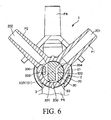
FIG. 6 is a sectional view, taken along line A-A, of the multi-way cock shown inFIG. 5 . - [
FIG. 7 ]
FIG. 7 is a sectional view, taken along line B-B, of the multi-way cock shown inFIG. 5 . - [
FIG. 8 ]
FIG. 8 shows sectional views of a wall portion of the casing and a lever of the multi-way cock in the liquid dispensing circuit shown inFIG. 1 . - [
FIG. 9 ]
FIG. 9 shows sectional views schematically illustrating a flow channel changeover pattern in the multi-way cock shown inFIG. 5 . - [
FIG. 10 ]
FIG. 10 shows sectional views schematically illustrating a flow channel changeover pattern in the multi-way cock shown inFIG. 5 . - [
FIG. 11 ]
FIG. 11 shows sectional views schematically illustrating a flow channel changeover pattern in the multi-way cock shown inFIG. 5 . - [
FIG. 12 ]
FIG. 12 shows sectional views schematically illustrating a flow channel changeover pattern in the multi-way cock shown inFIG. 5 . - Now, a liquid dispensing circuit according to the present invention will be described in detail below, based on a preferred embodiment shown in the accompanying drawings.
-
FIG. 1 is a perspective view showing an embodiment of the liquid dispensing circuit according to the present invention, andFIG. 2 is a perspective view of the liquid dispensing circuit shown inFIG. 1 , showing a state in which a casing has been detached.FIG. 3 shows views of the casing of the liquid dispensing circuit shown inFIG. 1 , whereinFIG. 3(a) is a plan view andFIG. 3(b) is a side view.FIG. 4 is a sectional view of the casing of the liquid dispensing circuit shown inFIG. 1 ,FIG. 5 is a perspective view of a multi-way cock in the liquid dispensing circuit shown inFIG. 5 ,FIG. 6 is a sectional view, taken along line A-A, of the multi-way cock shown inFIG. 5 ,FIG. 7 is a sectional view, taken along line B-B, of the multi-way cock shown inFIG. 5 , andFIG. 8 shows sectional views of a wall portion of the casing and a lever of the multi-way cock in the liquid dispensing circuit shown inFIG. 1 .FIGS. 9 to 12 schematically illustrate flow channel changeover patterns in the multi-way cock shown inFIG. 5 , whereinFIGS. 9(a) to 12(a) are each a plan view,FIGS. 9(b) to 12(b) are each a sectional view taken along line A-A ofFIG. 5 , andFIGS. 9(c) to 12(c) are each a sectional view taken along line B-B ofFIG. 5 . - Incidentally, in the following description, the upper side in
FIGS. 1 ,5 and8 will be referred to as "upper" or "upper end," while the lower side will be referred to as "lower" or "lower end." - The
liquid dispensing circuit 10 shown in these figures is, for example, a circuit (device) which is used at the time of treating coronary arterial stenosis for dispensing (injecting) physiological saline or a radiopaque material into a patient (a person for whom the circuit is to be used). - As shown in
FIGS. 1 to 4 , theliquid dispensing circuit 10 includes: a multi-way cock (flow channel changeover means) 1 which has a first port P1, a second port P2, a third port P3, a fourth port P4, a fifth port P5, a sixth port P6 and alever 32; afirst line 51; asecond line 52; athird line 53; afourth line 54; afifth line 55; and a casing (housing) 81 for housing some (most) of these members. Thecasing 81 has a box-like shape which is flat and of which corner portions are rounded. In addition, themulti-way cock 1 is fixedly disposed inside thecasing 81 so that itslever 32 is situated on the outer side (upper side) of awall portion 82, on the upper side inFIG. 1 , of thecasing 81. Incidentally, themulti-way cock 1 and thecasing 81 will be described in detail later. - The
second line 52 is a line through which to connect the second port P2 and a pressure sensor (blood pressure detection means) (not shown) for detecting the blood pressure of a patient, and has atube 62. - Specifically, the
tube 62 is connected at a proximal end thereof to the second port P2. Thetube 62 is, at a distal end thereof from an intermediate portion thereof, disposed on (led out to) the outside of thecasing 81, and thetube 62 is connected at the distal end thereof to the pressure sensor. For example, arterial pressure (blood pressure in the coronary artery) or the like is measured (detected) by the pressure sensor, and the measurement result (detection result) is displayed on a monitor (display means) which is not shown. - The
third line 53 is a line through which the third port P3 and a container (vial or the like) (not shown) reserving physiological saline are connected, and hastubes check valve 71 and an air vent integraltype bottle needle 75. In the configuration shown, thecheck valve 71 used is one which permits tubes to be connected (coupled) to both end portions thereof.
Specifically, thetube 63 is connected at a proximal end thereof to the third port P3, thetube 63 is connected at a distal end thereof to one end side of thecheck valve 71, and thetube 64 is connected at a proximal end thereof to the other end side of thecheck valve 71. Thetube 64 is, at a distal end thereof from an intermediate portion thereof, disposed on the outside of thecasing 81, and the air vent integraltype bottle needle 75 is connected to the distal end of thetube 64. Thebottle needle 75 is connected to the container (not shown) reserving the physiological saline. - In addition, the
check valve 71 is provided so as to permit a liquid (fluid) to flow therethrough from the side of the bottle needle 75 (physiological saline) to the side of the third port P3 (multi-way cock 1) and to inhibit the liquid from flowing therethrough in the reverse direction. Incidentally, the directions of parenthesized arrows in the vicinities of thecheck valves 71 to 73 inFIG. 2 indicate the directions in which liquid can flow. - The
fourth line 54 is a line through which the fourth port P4 and a tube (flow channel) communicating with a blood vessel of the patient are connected, and has thecheck valve 72, abranched connector 77 composed of a three-way branch pipe (T-pipe, Y-pipe, non-right angled T-pipe or the like),tubes check valve 72 used is one which is provided at one end portion thereof with a female-type Luer taper, and is provided at the other end portion thereof with a male-type Luer taper. In addition, a port of the branchedconnector 77 on the side for connection with thecheck valve 72 is formed with a female-type Luer taper, and the remaining two ports of the branchedconnector 77 are tapered in shape so as to permit tubes to be connected thereto. - Specifically, the female-type Luer taper on one end side of the
check valve 72 is connected to the fourth port P4, the male-type Luer taper on the other end side of thecheck valve 72 is connected to a female-type Luer taper formed at one port of the other two ports of the branchedconnector 77, and thetube 65 is connected at the proximal end thereof to the other port of the branchedconnector 77. Thistube 65 is, at the distal end thereof from an intermediate portion thereof, disposed on the outside of thecasing 81, and thetube 65 is connected at the distal end thereof to one of the ports of the three-way cock (drug dispensing cock) 74. Thetube 66 is connected at the proximal end thereof to the other one port of the three-way cock 74, and thetube 66 is to be connected at the distal end thereof to the proximal end of a catheter (tube) which is not shown. The distal end of the catheter is inserted into a patient's blood vessel, and extends through the blood vessel to reach the vicinity of a stenosed part (target part) of a coronary artery. - In addition, the
check valve 72 is provided so as to permit a liquid (fluid) to flow therethrough from the fourth port P4 (multi-way cock 1) side to the branched connector 77 (patient) side and to inhibit the liquid from flowing in the reverse direction. - Besides, that port (remaining port) of the three ports of the three-
way cock 77 which is not connected to anything is used, for example, in the case of dispensing a drug such as nitroglycerin or in the case of drawing blood (arterial blood). - The
first line 51 is a line through which the first port P1 and the fourth line are connected, and has atube 61. - Specifically, the
tube 61 is connected (coupled) at the proximal end (one end) thereof to the first port P1, and thetube 61 is connected at the distal end (the other end) thereof to one of the ports of the branchedconnector 77. - The
fifth line 55 is a line through which the fifth port P5 and a container (bag, bottle or the like) reserving a radiopaque material therein (not shown) are connected, and hastubes check valve 73 and an air vent integraltype bottle needle 76. In the configuration shown, thecheck valve 73 used is one which permits tubes to be connected to both end portions thereof. - Specifically, the
tube 67 is connected at the proximal end thereof to the fifth port P5, thetube 67 is connected at the distal end thereof to one end side of thecheck valve 73, and thetube 68 is connected at the proximal end thereof to the other end side of thecheck valve 73. Thistube 68 is, at the distal end thereof from an intermediate portion thereof, disposed on the outside of thecasing 81, and the air vent integraltype bottle needle 76 is connected to the distal end of thetube 68. Thebottle needle 76 is to be connected to the container (not shown) reserving the radiopaque material. - In addition, the
check valve 73 is provided so as to permit a liquid to flow therethrough from the bottle needle 76 (radiopaque material) side to the fifth port P5 (multi-way cock 1) side and to inhibit the liquid from flowing in the reverse direction. - Incidentally, the
bottle needle 75 and thebottle needle 76 are, or thetube 64 and thetube 68 are, preferably colored in different colors. This make it possible to prevent misconnection of the bottle needles 75, 76. In other words, connection of thebottle needle 75 to the container reserving the physiological saline therein and connection of thebottle needle 76 to the container reserving the radiopaque material therein can be carried out in an assured manner. - The sixth port P6 is to be connected to liquid feeding means for feeding a liquid from one line of the first to
fifth lines 51 to 55 to another line through themulti-way cock 1. Specifically, the sixth port P6 is connected to asyringe 11 provided as the liquid feeding means, either directly or via a tube (flow channel) or the like. - In the configuration shown, the
syringe 11 is connected directly to the sixth port P6. In this case, that portion of thecasing 81 which corresponds to the sixth port P6 is formed with atube body 85 for holding an outer tube of thesyringe 11, and a distal end portion of the sixth port P6 is situated inside thetube body 85. This ensures that when thesyringe 11 is connected to the sixth port P6, the outer tube of thesyringe 11 is fitted into thetube body 85, whereby thesyringe 11 is held. - Now, the
multi-way cock 1 will be described.
As shown inFIGS. 5 to 7 , the multi-way cock (flow channel changeover means) 1 is a two-stage type multi-way cock, and has acock body 2, acock 3, and acover 4. - The
cock body 2 has a thick-walled hollow cylindrical part (tubular part) 20. The hollowcylindrical part 20 has afirst portion 21 and asecond portion 22 which are provided side by side along an axis (center axis) 101. In the configuration shown, thefirst portion 21 is disposed on the upper side (upper stage), and thesecond portion 22 is disposed on the lower side (lower stage). Incidentally, a configuration in which, on the contrary to the just-mentioned, thefirst portion 21 is disposed on the lower side and thesecond portion 22 on the upper side, may also be adopted. - At the outer circumference of the
first portion 21, the first port P1 and the second port P2 having tubular bodies (branch tubes) projecting outward in radial directions (directions perpendicular to the axis 101) at a predetermined angle therebetween are provided (formed) side by side along the circumferential direction. In addition,flow channels lumen 200 of the hollowcylindrical part 20 at an equal height position. - Incidentally, while the angular interval between the first port P1 and the second port P2 is 90° in the configuration shown, the angular interval naturally is not limited to this value.
- Besides, at the outer circumference of the
second portion 22, the third port P3, the fourth port P4, the fifth port P5 and the sixth port P6 having tubular bodies (branch tubes) projecting outward in radial directions (directions perpendicular to the axis 101) at predetermined angles therebetween are sequentially provided (formed) side by side along the circumferential direction. Specifically, the third port P3, the fourth port P4, the fifth port P5 and the sixth port P6 are disposed in this order and in such a manner that the third port P3 and the first port P1 project in the same direction while the fifth port P5 and the second port P2 project in the same direction. Incidentally, in plan view (as viewed from the upper side inFIG. 5 ), the third port P3 and the first port P1 coincide (overlap) with each other, while the fifth port P5 and the second port P2 coincide with each other. In addition,flow channels lumen 200 of the hollowcylindrical part 20 at an equal height position. - Incidentally, while the angular interval between the third port P3 and the fourth port P4 and the angular interval between the fourth port P4 and the fifth port P5 are each 45° in the configuration shown, the angular intervals naturally are not limited to this value. Besides, while the angular interval between the sixth port P6 and the third port P3 and the angular interval between the fifth port P5 and the sixth port P6 are each 135° in the configuration shown, the angular intervals naturally are not limited to this value.
- In addition, distal end portions of the first to third ports P1 to P3 and the fifth port P5 gradually decrease in outside diameter toward the distal end. In other words, the distal end portions are gradually decreasing outside diameter portions (tapered portions). This enables easy connection (coupling) of tubes or the like to the distal end portions of the first to third ports P1 to P3 and the fifth port P5.
- Besides, the distal end portion of the fourth port P4 is formed with a male-type Luer taper. This enables easy connection of a female-type Luer taper or the like to the distal end portion of the fourth port P4.
- In addition, the distal end portion of the sixth port P6 is formed with a female-type Luer taper. This enables easy connection of a syringe or the like to the distal end portion of the sixth port P6.
- The
cock 3 has a trunk part (insertion part) 30, alever mounting part 31, and a lever (operating part) 32. With a turning operation applied to thecock 3, namely, with thecock 3 turned (rotated in a forward direction or a reverse direction) relative to thecock body 2, open/closed states of the first to sixth ports P1 to P6 provided in thefirst portion 21 and thesecond portion 22 are selected. - The
trunk part 30 is solid-cylindrical in shape, and it is turnably inserted (fitted) in thelumen 200 of the hollowcylindrical part 20 in a gas-tight or liquid-tight manner. Therefore, the outside diameter of thetrunk part 30 in the condition where thecock 3 has been drawn out of the hollowcylindrical part 20 is preferably a little greater, for example greater by about 1 to 6%, than the inside diameter of the hollowcylindrical part 20. - That portion of the
trunk part 30 which corresponds to thefirst portion 21 is formed therein with afirst flow channel 33 through which the first port P1 and the second port P2 formed in thefirst portion 21 communicate with each other (in the case where the number of ports is three or more, the ports communicate with one another in a predetermined combination). Incidentally, the state in which a port is communicating with another port will be referred to as "open state," while the state in which a port is not communicating with any other port will be referred to as "closed state." - The
first flow channel 33 is so formed that both the first port P1 and the second port P2 can simultaneously be set into an open state or a closed state (in the case where the number of ports is three or more, thefirst flow channel 33 is so formed that predetermined two of the ports can be simultaneously set into an open state or a closed state). - Specifically, the
first flow channel 33 includes: afirst part 331 which is formed (provided) at an outer circumferential surface of thetrunk part 30 and extends in the circumferential direction of thetrunk part 30; asecond part 332 which extends from one end portion of thefirst part 331 and penetrates thetrunk part 30 without passing through acenter axis 102 of thetrunk part 30 or the outer circumference of thetrunk part 30; and athird part 333 which extends from the other end portion of thefirst part 331 and penetrates thetrunk part 30 without passing through thecenter axis 102 of thetrunk part 30 or the outer circumference of thetrunk part 30. Incidentally, in the configuration shown, thefirst part 331 is arcuate in shape. In addition, thesecond part 332 is a flexed line-like (bent or curved bar-like) in shape. Besides, thethird part 333 is rectilinear (bar-like) in shape. In addition, thesecond part 332 and thethird part 333 open at the outer circumferential surface of thetrunk part 30, to form distal openings (openings) 334 and 335 which each have a circular shape, a tetragonal shape or the like shape. - The first to
third parts 331 to 333 are formed at such a height as to coincide with theflow channels cock 3 is fitted in thecock body 2. - Besides, that portion of the
trunk part 30 which corresponds to thesecond portion 22 is formed therein with asecond flow channel 34 through which the third to sixth ports P3 to P6 formed in thesecond portion 22 communicate with one another in a predetermined combination. - The
second flow channel 34 is so formed that predetermined three ports of the third to sixth ports P3 to P6 can be simultaneously set into an open state or a closed state, and that the turning angle range of thecock 3 for putting the predetermined three ports into a closed state is greater than the turning angle range of thecock 3 for putting the predetermined three ports into an open state. - Specifically, the
second flow channel 34 is formed in an X shape. More specifically, thesecond flow channel 34 includes afirst part 341, asecond part 342, athird part 343 and afourth part 344 which extend in radial directions of thetrunk part 30 at predetermined angles therebetween and communicate with one another in the vicinity of a central portion of thetrunk part 30. In this case, thefirst part 341, thesecond part 342, thethird part 343 and thefourth part 344 are arranged in this order along a counterclockwise direction. In addition, the first tofourth parts 341 to 344 open at the outer circumferential surface of thetrunk part 30, to form distal openings (openings) which each have a circular shape, a tetragonal shape or the like shape. Besides, the angle formed between thefirst part 341 and thesecond part 342 and the angle formed between thethird part 343 and thefourth part 344 are equal to each other, and are each smaller than 90°. On the other hand, the angle formed between thesecond part 342 and thethird part 343 and the angle formed between thefourth part 344 and thesecond part 342 are equal to each other, and are each greater than 90°. Incidentally, while the angle formed between thefirst part 341 and thesecond part 342 and the angle formed between thethird part 343 and thefourth part 344 are each 45° in the configuration shown, the angles naturally are not limited to this value. Also, while the angle formed between thesecond part 342 and thethird part 343 and the angle formed between thefourth part 344 and thefirst part 341 are each 135° in the configuration shown, the angles naturally are not limited to this value. - The first to
fourth parts 341 to 344 are formed at such a height position as to coincide with theflow channels 203 to 206 in the ports P3 to P6 in the cock fitted state. - In addition, the
second flow channel 34 and thefirst flow channel 33 do not communicate with each other. This ensures that the opening/closing of the first port P1 and the second port P2 formed in thefirst portion 21 and the opening/closing of the third to sixth ports P3 to P6 formed in thesecond portion 22 can be controlled independently. - As shown in
FIG. 5 , at the upper side of thetrunk part 30, the lever mounting part (operating part mounting part) 31 is provided which is greater than the outside diameter of thetrunk part 30 and to which thelever 32 is mounted (fitted). Thetrunk part 30 and thelever mounting part 31 are preferably formed monolithically. Thelever mounting part 31 is in the state of being exposed to the upper side of the hollowcylindrical part 20 in the cock fitted state. - To the
lever mounting part 31, thelever 32 being bar-like in shape and extending (protruding) in one direction is mounted so as to protrude radially outward. In the state wherein thelever 32 is mounted to thelever mounting part 31, aturning center portion 322 of thelever 32 and thelever mounting part 31 are fitted to each other. Specifically, thelever 32 would not be turned relative to thelever mounting part 31, and a turning operation of thecock 3 is effected by gripping thelever 32 by fingers and exerting a torque on thelever 32. For this purpose, therefore, both side surfaces of thelever 32 are each formed with arugged pattern 321 as anti-slipping means. - In addition, in the configuration shown, in the state wherein the
lever 32 is mounted to thelever mounting part 31, the protruding direction of thelever 32 is between the protruding direction of thethird part 343 and the protruding direction of thefourth part 344, of thesecond flow channel 34 from thecenter axis 102, as can be seen inFig. 9 . - The
cock 3 can be moved, by turning thereof, to a priming position for priming before use, a radiopaque material dispensing position for dispensing a radiopaque material into a patient, a physiological saline dispensing position for dispensing physiological saline into the patient, and a blood pressure detection position for detecting the blood pressure of the patient by a pressure sensor. - In this case, the radiopaque material dispensing position, the physiological saline dispensing position and the blood pressure detection position are preferably provided concentratedly within the range of a center angle of not more than 120°, and the priming position is provided outside the range. Incidentally, in the configuration example shown, the radiopaque material dispensing position, the physiological saline dispensing position and the blood pressure detection position are provided concentratedly within the range of a center angle of 45°.
- As shown in
FIG. 5 , the cover (seal member) 4 is a member which has a projecting portion (not shown) at a central portion thereof, and is mounted to the lower end of the hollowcylindrical part 20 of thecock body 2 in such a manner as to seal off the lower end of thelumen 200. - In this case, the projecting portion of the
cover 4 is fitted (firmly attached) into a hole (not shown) formed in a lower end portion of thetrunk part 30. This makes it possible to prevent thetrunk part 30 of thecock 3 from being shifted in the direction of theaxis 101 relative to the hollowcylindrical part 20 of thecock body 2 or being disengaged. - Incidentally, the
cover 4 may be firmly attached to the hollowcylindrical part 20, not to thetrunk part 30. - Materials for forming the
cock body 2, thecock 3 and thecover 4 are not specifically restricted. Examples of the materials include polyethylene, polypropylene, polybutadiene and the like polyolefins, polyurethane, polystyrene, polymethyl methacrylate and the like acrylic resins, polycarbonate, polyamides, polyethylene terephthalate and the like polyesters, polyacetal, ABS resin, AS resin, ionomers and other fluoro-resins, and the like resin materials, thermoplastic elastomers based on polyurethane, polyester, polyamide, olefin, styrene or the like, stainless steel, aluminum, titanium and the like metallic materials, and glasses, which may be used either singly or in an arbitrary combination (for example, as a composite material). - Incidentally, in order to secure visibility of the inside of the
multi-way cock 1, for example, a light-transmitting material (transparent or translucent material) may be used for forming thecock body 2. - In addition, as shown in
FIG. 8 , thelever 32 of themulti-way cock 1 is formed, at a position deviated from theturning center portion 322, with arecess 323 opening to the lower side. Inside therecess 323, apin 324 formed with aflange 326 at an outer circumferential portion thereof is disposed in a vertically movable manner. Besides, between theflange 326 of thepin 324 and an upper portion of the inside of therecess 323, a coil spring (biasing means) 325 is disposed in a contracted state. By an elastic force (restoring force) of thecoil spring 325, thepin 324 is biased downward. - On the other hand, as shown in
FIGS. 1 ,3 and8 , an outside surface of thewall portion 82 of thecasing 81 is formed with agroove 83 in the vicinity of thelever 32. Thegroove 83 extends in an arcuate shape along a circle the center of which coincides with the center of turning (turning center) of thecock 3 and the radius of which is equal to the distance between the turning center of thecock 3 and thepin 324. This ensures that when thecock 3 is turned by operating thelever 32 starting from the state shown inFIG. 8(a) , thepin 324 is moved to a position on the upper side of thegroove 83 as shown inFIG. 8(b) , and thepin 324 is moved downward by the biasing force of the coil spring, to be inserted into thegroove 83. Incidentally, once thepin 324 is inserted into thegroove 83, thepin 324 would not come out of thegroove 83. - Here, initially, the
cock 3 is situated in the priming position shown inFIG. 9 . The priming position is provided in such a position that thepin 324 is not inserted in thegroove 83. As shown inFIG. 9 , when thecock 3 is situated in the priming position, thedistal opening 334 of thesecond part 332 of thefirst flow channel 33 communicates with the first port P1, and thedistal opening 335 of thethird part 333 communicates with the second port P2, whereby the first port P1 and the second port P2 are set in an open state wherein these ports communicate with each other via thefirst flow channel 33, whereas the third port P3 and the fourth port P4 and the sixth port P6 are set in an open state wherein these ports communicate with one another via thesecond flow channel 34. - Then, when the
cock 3 is turned by operating thelever 32 as above-mentioned after priming is conducted, thepin 324 is inserted into thegroove 83. - When the
lever 32 is operated to rotate (turn) thecock 3 clockwise inFIG. 5 relative to thecock body 2, thepin 324 comes into contact (engagement) with an edge portion on one end side of thegroove 83, resulting in that thecock 3 cannot be rotated further clockwise inFIG. 5 . The position of thecock 3 in this instance is the physiological saline dispensing position, where the positional relationship between the first to sixth ports P1 to P6 of thecock body 2 and the trunk part 30 (thefirst flow channel 33 and the second flow channel 34) of thecock 3 is as shown inFIG. 11 . - As shown in
FIG. 11 , when thecock 3 is situated in the physiological saline dispensing position, the first port P1 and the second port P2 are each set in a closed state, whereas the third port P3 and the fourth port P4 and the sixth port P6 are set in an open state wherein these ports communicate with one another via thesecond flow channel 34. - In addition, when the
cock 3 is rotated (in the configuration shown, rotated by 45°) counterclockwise inFIG. 5 relative to thecock body 2 from the physiological saline dispensing position, thepin 324 comes into contact with an edge portion on the other end side of thegroove 83, resulting in that thecock 3 cannot be rotated further counterclockwise inFIG. 5 . The position of thecock 3 in this instance is the radiopaque material dispensing position, where the positional relationship between the first to sixth ports P1 to P6 of thecock body 2 and the trunk part 30 (thefirst flow channel 33 and the second flow channel 34) of thecock 3 is as shown inFIG. 10 . - As shown in
FIG. 10 , when thecock 3 is situated in the radiopaque material dispensing position, the first port P1 and the second port P2 are each set in a closed state, whereas the fourth port P4 and the fifth port P5 and the sixth port P6 are set in an open state wherein these ports communicate with one another via thesecond flow channel 34. - Besides, the time when the
cock 3 is situated between the radiopaque material dispensing position and the physiological saline dispensing position as shown inFIG. 12 is the time when thecock 3 is situated in the blood pressure detection position. As shown inFIG. 12 , when thecock 3 is situated in the blood pressure detection position, thefirst part 331 of thefirst flow channel 33 communicates with each of the first port P1 and the second port P2, whereby the first port P1 and the second port P2 are set in an open state wherein these ports communicate with each other via thefirst flow channel 33, whereas the third port P3, the fourth port P4, the fifth port P5 and the sixth port P6 are each set in a closed state. - Thus, by the
pin 324 and thegroove 83, the turning range of thecock 3 relative to the hollowcylindrical part 20 is restrained within such a range that thecock 3 can be moved into the radiopaque material dispensing position, the physiological saline dispensing position and the blood pressure detection position. In addition, by thepin 324 and thegroove 83, thecock 3 is positioned into each of the radiopaque material dispensing position and the physiological saline dispensing position. Besides, after thepin 324 is inserted into thegroove 83, thepin 324 and thegroove 83 prevents thecock 3 from being moved into the priming position. In other words, once thecock 3 is moved from a first region in which the priming position is provided into a second region in which the radiopaque material dispensing position, the physiological saline dispensing position and the blood pressure detection position are provided, thecock 3 cannot be returned into the first region. - Therefore, the
pin 324 and thegroove 83 constitute positioning means by which the turning range of thecock 3 relative to the hollowcylindrical part 20 is restricted. Incidentally, when the positioning means is not functioning, in other words, when thepin 324 is not inserted in thegroove 83, thecock 3 can be moved into the priming position. - Incidentally, the upper surface of the
wall portion 82 of thecasing 81 is preferably provided with indicators respectively indicating the priming position, the radiopaque material dispensing position, the physiological saline dispensing position and the blood pressure detection position. This makes it possible to move thecock 3 into a target position assuredly. - Now, operations of (a method of using) the
liquid dispensing circuit 10 will be described below referring toFIGS. 2 and9 to 12 . - First, priming is conducted. At the time of priming, the
lever 32 is operated so as to move thecock 3 into the priming position shown inFIG. 9 . This results in that, as above-mentioned, thedistal opening 334 of thesecond part 332 of thefirst flow channel 33 communicates with the first port P1, and thedistal opening 335 of thethird part 333 communicates with the second port P2, whereby the first port P1 and the second port P2 are set in an open state wherein these ports communicate with each other via thefirst flow channel 33, whereas the third port P3 and the fourth port P4 and the sixth port P6 are set in an open state wherein these ports communicate with one another via thesecond flow channel 34. - Next, a
pusher 111 in thesyringe 11 is moved toward the proximal end. This results in that the physiological saline in the container (not shown) is introduced into thesyringe 11 via thebottle needle 75, thetube 64, thecheck valve 71, thetube 63, the third port P3, thesecond follow channel 34 and the sixth port P6. Subsequently, thepusher 111 in thesyringe 11 is moved toward the distal end (in the distal direction). This causes the physiological saline in thesyringe 11 to flow through the sixth port P6, thesecond flow channel 34, the fourth port P4, thecheck valve 72, the branchedconnector 77, thetube 65, the three-way cock 74 and thetube 66, and to flow out via the distal end of thetube 66. In addition, the physiological saline flows from the branchedconnector 77 through thetube 61, the first port P1, thefirst flow channel 33, the second port P2 and thetube 62, to flow out via the distal end of thetube 62. As a result, each of the just-mentioned portions can be primed. - Next, the
lever 32 is operated so as to move thecock 3 into the radiopaque material dispensing position shown inFIG. 10 . This results in that, as above-mentioned, the first port P1 and the second port P2 are each set in a closed state, whereas the fourth port P4 and the fifth port P5 and the sixth port P6 are set in an open state wherein these ports communicate with one another via thesecond flow channel 34. - Subsequently, the
pusher 111 in thesyringe 11 is moved toward the proximal end. This causes the radiopaque material in the container (not shown) to be introduced into thesyringe 11 via thebottle needle 76, thetube 68, thecheck valve 73, thetube 67, the fifth port P5, thesecond flow channel 34 and the sixth port P6. - Next, the
pusher 111 in thesyringe 11 is moved toward the distal end. This causes the radiopaque material in thesyringe 11 to flow through the sixth port P6, thesecond flow channel 34, the fourth port P4, thecheck valve 72, the branchedconnector 77, thetube 65, the three-way cock 74 and thetube 66, and to flow out via the distal end of thetube 66. As a result, each of the just-mentioned portions can be primed. By these operations, priming of theliquid dispensing circuit 10 is completed, followed by a predetermined procedure. Incidentally, the description of the predetermined procedure is omitted. - In the case of dispensing the radiopaque material into a patient, the
lever 32 is operated so as to move thecock 3 into the radiopaque dispensing position shown inFIG. 10 . This ensures that, as above-mentioned, the first port P1 and the second port P2 are each set in a closed state, whereas the fourth port P4 and the fifth port P5 and the sixth port P6 are set in an open state wherein these ports communicate with one another via thesecond flow channel 34. As a result, the patient's artery and the pressure sensor are disconnected from each other. - Next, the
pusher 111 in thesyringe 11 is moved toward the proximal end. This causes the radiopaque material in the container (not shown) to be introduced into thesyringe 11 via thebottle needle 76, thetube 68, thecheck valve 73, thetube 67, the fifth port P5, thesecond flow channel 34 and the sixth port P6. In this case, by the action of thecheck valve 72, the patient's blood is inhibited from flowing to thesyringe 11 side. - Subsequently, the
pusher 111 in thesyringe 11 is moved toward the distal end. This causes the radiopaque material in thesyringe 11 to flow out via the sixth port P6, thesecond flow channel 34, the fourth port P4, thecheck valve 72, the branchedconnector 77, thetube 65, the three-way cock 74, thetube 66 and a catheter (not shown) connected to thetube 66, into the vicinity of a stenosed part of the patient's coronary artery. - After the
cock 3 is thus situated in the first position, the radiopaque material can be continuously sucked in and discharged by only operating thesyringe 11, without operating thelever 32. - Besides, in the case of dispensing the physiological saline into the patient, the
lever 32 is operated so as to move thecock 3 into the physiological saline dispensing position shown inFIG. 11 . This ensures that, as above-mentioned, the first port P1 and the second port P2 are each set in a closed state, whereas the third port P3 and the fourth port P4 and the sixth port P6 are set in an open state wherein these ports communicate with one another via thesecond flow channel 34. This results in a state in which the patient's artery and the pressure sensor are disconnected from each other. - Next, the
pusher 111 in thesyringe 11 is moved toward the proximal end. This causes the physiological saline in the container (not shown) to be introduced into thesyringe 11 via thebottle needle 75, thetube 64, the check calve 71, thetube 63, the third port P3, thesecond flow channel 34 and the sixth port P6. In this case, by the action of thecheck valve 72, the patient's blood is inhibited from flowing to thesyringe 11 side. - Subsequently, the
pusher 111 in thesyringe 11 is moved toward the distal end. This causes the physiological saline in thesyringe 11 to flow out through the sixth port P6, thesecond flow channel 34, the fourth port P4, thecheck valve 72, the branchedconnector 77, thetube 65, the three-way cock 74, thetube 66 and a catheter (not shown) connected to thetube 66, into the vicinity of the stenosed part of the patient's coronary artery. - After the
cock 3 is thus situated in the second position, the physiological saline can be continuously sucked in and discharged by only operating thesyringe 11, without operating thelever 32. - In addition, in the case of measuring the artery pressure (the blood pressure in the coronary artery) of the patient and displaying the measurement result on a monitor (not shown), the
lever 32 is operated so as to move thecock 3 into the blood pressure detection position shown inFIG. 12 . This ensures that, as above-mentioned, thefirst part 331 of thefirst flow channel 33 communicates with each of the first port P1 and the second port P2, whereby the first port P1 and the second port P2 are set in an open state wherein these ports communicate with each other via thefirst flow channel 33, whereas the third port P3, the fourth port P4, the fifth port P5 and the sixth port P6 are each set in a closed state. This results in a state in which the patient's artery and the pressure sensor are connected with each other, and the patient's artery pressure is measured by the pressure sensor through the catheter, thetube 66, the three-way cock 74, thetube 65, the branchedconnector 77, thetube 61, the first port P1, thefirst flow channel 33, the second port P2 and thetube 62, the measurement result being displayed on the monitor. - As has been described above, according to the
liquid dispensing circuit 10, by only turning the single lever 32 (cock 3) it is possible to freely select the opening/closing of the first to sixth ports P1 to P6, and to easily and swiftly perform complicated flow channel changing-over operations. - To be more specific, when the
cock 3 is situated in the priming position, priming can be securely carried out by only operating thesyringe 11. In addition, when thecock 3 is situated in the radiopaque material dispensing position, the radiopaque material can continuously be sucked in and discharged by only operating thesyringe 11, without operating thelever 32. Besides, when thecock 3 is situated in the physiological saline dispensing position, the physiological saline can be continuously sucked in and discharged by only operating thesyringe 11, without operating thelever 32. Furthermore, when thecock 3 is situated in the blood pressure detection position, the patient's artery pressure can be measured and displayed on the monitor. - In addition, since the
first portion 21 and thesecond portion 22 are provided side by side along theaxis 101 of the hollowcylindrical part 20, downsizing of themulti-way cock 1 can be ensured. - While the liquid dispensing circuit according to the present invention has been described above based on the embodiment shown in the drawings, the invention is not to be restricted to the above embodiment, and the configuration of each part can be replaced by a part with an arbitrary configuration that has the same or similar function. Besides, other arbitrary structures may be added to the present invention.
- Incidentally, in the present invention, the number of the ports provided at the outer circumference of the first portion of the tubular part of the cock body is not limited to two but may be three or more.
- In addition, in the present invention, the number of the ports provided at the outer circumference of the second portion of the tubular part of the cock body is not limited to four but may be five or more.
- Besides, in the present invention, the number of those portions of the tubular part of the cock body which are provided with the ports is not limited to two (the first portion and the second portion) but may be three or more; similarly, the number of the flow channel formed in the trunk part of the cock is not limited to two (the first flow channel and the second flow channel) but may be three or more.
- In other words, in the present invention, for example, a configuration may be adopted in which the tubular part of the cock body further has a third portion provided at the outer circumference thereof with at least two ports, the trunk part of the cock is formed further with a third flow channel through which the ports provided in the third portion communicate with one another in a predetermined combination, and the opening/closing of the ports provided in the first portion, the second portion and the third portion is selected by turning the cock. In this case, the third portion is preferably provided in a line with the first portion and the second portion along the axis (center axis) of the tubular part. In addition, the third flow channel preferably communicates with neither the first flow channel nor the second flow channel.
- Besides, in the present invention, an operating part for turning the cock is not restricted to the above-described lever; for example, the operating part may be a part extended in two or more directions, a handle, a dial or the like.
- In addition, the use of the liquid dispensing circuit according to the present invention is not particularly restricted; thus, the liquid dispensing circuit is applicable not only to the above-described embodiment but also to the cases where a multiplicity of tubes are used, such as, for example, an anesthetic procedure.
- According to the present invention, a priming operation before use of the liquid dispensing circuit can be carried out easily and assuredly, and complicated flow channel changing-over operations during use of the liquid dispensing circuit can be carried out easily and swiftly.
- Specifically, the tubular part of the cock body of the multi-way cock has the first portion and the second portion provided with groups of ports, and the cock for selecting the communicating/non-communicating (open/closed) states of these ports is a common (single) cock, and, therefore, complicated flow channel changing-over operations can be carried out easily and speedily.
- In addition, when the cock is situated in the priming position, the first port and the second port are set in an open state wherein these ports communicate with each other via the first flow channel, whereas the third port and the fourth port and the sixth port are set in an open state wherein these ports communicate with one another via the second flow channel. In this state, therefore, physiological saline can be fed to the liquid feeding means side via the third line, the third port, the second flow channel and the sixth port by the liquid feeding means, for reserving the physiological saline on the side. This enables priming of the third line, the third port, the second flow channel and the sixth port. Then, by the liquid feeding means, the physiological saline can be fed from the sixth port to the second flow channel, the fourth port and the fourth line, whereby priming of the second flow channel, the fourth port and the fourth line can be achieved. In addition, since the physiological saline fed by the liquid feeding means is fed also from the fourth line into the first line, the physiological saline is fed to the first line, the first port, the first flow channel, the second port and the second line, whereby priming of the first line, the first port, the first flow channel, the second port and the second line can be achieved.
- Besides, since the first portion and the second portion of the multi-way cock are provided in a line along the axis of the tubular part, downsizing of the multi-way cock can be ensured. Accordingly, the present invention has industrial applicability.
Claims (8)
- A liquid dispensing circuit (10) comprising:a multi-way cock (1) including a cock body (2) which is provided with a tubular part (20) having a first portion (21) and a second portion (22) provided side by side along an axis (101), with a first port (P1) and a second port (P2) formed at an outer circumference of the first portion (21) side by side along a circumferential direction, and with a third port (P3), a fourth port (P4), a fifth port (P5), and a sixth port (P6) sequentially provided at an outer circumference of the second portion (22) side by side along a circumferential direction, and a cock (3) having a trunk part (30) which is turnably inserted in the tubular part (20) and which is formed with a first flow channel (33) making the first port (P1) and the second port (P2) provided in the first portion (21) communicate with each other, and with a second flow channel (34) making the third port (P3), the fourth port (P4), the fifth port (P5) and the sixth port (P6) provided in the second portion (22) communicate with one another in a predetermined combination;a second line (52) through which the second port (P2) and blood pressure detection means for detecting the blood pressure of a patient are connected;a third line (53) through which the third port (P3) and a container reserving physiological saline are connected;a fourth line (54) through which the fourth port (P4) and a flow channel communicating with a blood vessel of the patient are connected;a first line (51) through which the first port (P1) and the fourth line (54) are connected; anda fifth line (55) through which the fifth port (P5) and a container reserving a radiopaque material are connected,wherein the sixth port (P6) is connected to liquid feeding means (11) for feeding a liquid from one of the first line (51), the second line (52), the third line (53), the fourth line (54) and the fifth line (55) to another line through the multi-way cock (1);the cock (3) can be moved by turning to a priming position for priming before use, a radiopaque material dispensing position for dispensing the radiopaque material to the patient, a physiological saline dispensing position for dispensing the physiological saline to the patient, and a blood pressure detection position for detecting the blood pressure of the patient by the pressure detection means; andwhen the cock (3) is situated in the priming position, the first port (P1) and the second port (P2) are in an open state wherein these ports communicate with each other through the first flow channel (33), and the third port (P3), the fourth port (P4) and the sixth port (P6) are in an open state wherein these ports communicate with one another through the second flow channel (34).
- The liquid dispensing circuit (10) according to claim 1, wherein the first flow channel (33) includes: a first part (331) provided in an outer circumferential surface of the trunk part (30) and extending in the circumferential direction of the trunk part (30); a second part (332) extending from one end portion of the first part (331), penetrating the trunk part (30) and forming a distal opening at the outer circumferential surface of the trunk part (30); and a third part (333) extending from the other end portion of the first part (331), penetrating the trunk part (30) and forming a distal opening at the outer circumferential surface of the trunk part (30).
- The liquid dispensing circuit (10) according to claim 2, wherein when the cock (3) is situated in the priming position, the distal opening of the second part (332) communicates with the first port (P1), and the distal opening of the third part (333) communicates with the second port (P2), whereby the first port (P1) and the second port (P2) are made to communicate with each other through the first flow channel (33).
- The liquid dispensing circuit (10) according to claim 2, wherein when the cock (3) is situated in the blood pressure detection position, the first part (331) communicates with both the first port (P1) and the second port (P2), whereby the first port (P1) and the second port (P2) are set in an open state wherein these ports communicate with each other through the first flow channel (33), whereas the third port (P3), the fourth port (P4), the fifth port (P5) and the sixth port (P6) are each set in a closed state.
- The liquid dispensing circuit (10) according to claim 1, wherein when the cock (3) is situated in the blood pressure detection position, the first port (P1) and the second port (P2) are set in an open state wherein these ports communicate with each other through the first flow channel (33), whereas the third port (P3), the fourth port (P4), the fifth port (P5) and the sixth port (P6) are each set in a closed state.
- The liquid dispensing circuit according to claim 1, wherein when the cock (3) is situated in the radiopaque material dispensing position, the first port (P1) and the second port (P2) are each set in a closed state, whereas the fourth port (P4), the fifth port (P5) and the sixth port (P6) are set in an open state wherein these ports communicate with one another through the second flow channel (34).
- The liquid dispensing circuit (10) according to claim 1, wherein when the cock (3) is situated in the physiological saline dispensing position, the first port (P1) and the second port (P2) are each set in a closed state, whereas the third port (P3), the fourth port (P4) and the sixth port (P6) are set in an open state wherein these ports communicate with one another through the second flow channel (34).
- The liquid dispensing circuit (10) according to claim 1, wherein the radiopaque material dispensing position, the physiological saline dispensing position and the blood pressure detection position are concentratedly provided within the range of a central angle of not more than 120°, and the priming position is provided outside the range.
Applications Claiming Priority (2)
| Application Number | Priority Date | Filing Date | Title |
|---|---|---|---|
| JP2010073415 | 2010-03-26 | ||
| PCT/JP2011/055694 WO2011118410A1 (en) | 2010-03-26 | 2011-03-10 | Liquid dispensing circuit |
Publications (2)
| Publication Number | Publication Date |
|---|---|
| EP2554212A1 true EP2554212A1 (en) | 2013-02-06 |
| EP2554212A4 EP2554212A4 (en) | 2014-08-20 |
Family
ID=44672971
Family Applications (1)
| Application Number | Title | Priority Date | Filing Date |
|---|---|---|---|
| EP11759217.0A Withdrawn EP2554212A4 (en) | 2010-03-26 | 2011-03-10 | LIQUID DISTRIBUTION CIRCUIT |
Country Status (5)
| Country | Link |
|---|---|
| US (1) | US9474890B2 (en) |
| EP (1) | EP2554212A4 (en) |
| JP (1) | JP5814227B2 (en) |
| CN (1) | CN102811764B (en) |
| WO (1) | WO2011118410A1 (en) |
Families Citing this family (4)
| Publication number | Priority date | Publication date | Assignee | Title |
|---|---|---|---|---|
| US9901730B2 (en) | 2012-07-31 | 2018-02-27 | Sugan Co., Ltd. | Stopcock flow path switching device |
| DE102013103986A1 (en) * | 2013-04-19 | 2014-10-23 | B. Braun Avitum Ag | Recirculation device of an extracorporeal blood treatment device |
| US12023463B2 (en) * | 2018-01-02 | 2024-07-02 | Cerner Innovation, Inc. | Clinical notifications |
| JP7713326B2 (en) * | 2021-07-16 | 2025-07-25 | 株式会社ジェイ・エム・エス | Operating device for three-way stopcock |
Family Cites Families (13)
| Publication number | Priority date | Publication date | Assignee | Title |
|---|---|---|---|---|
| US3678960A (en) * | 1970-06-08 | 1972-07-25 | Saul Leibinsohn | Stop cock |
| US5466228A (en) * | 1991-01-25 | 1995-11-14 | California State University, Fresno Foundation | Fluid control apparatus |
| US5540668A (en) * | 1995-01-20 | 1996-07-30 | Wilson, Jr.; Roland B. | Anti-cross contamination valve and fluid delivery systems using same |
| JPH09108360A (en) | 1995-10-04 | 1997-04-28 | Hiroko Umetsu | Manual contrast media injection device for blood vessel contrast |
| JP4034528B2 (en) * | 2001-04-17 | 2008-01-16 | 住友重機械工業株式会社 | Dispensing / dosing device for radioactive liquid |
| US6918893B2 (en) * | 2001-10-04 | 2005-07-19 | Scimed Life Systems, Inc. | Multiple port fluid control valves |
| US7172572B2 (en) * | 2001-10-04 | 2007-02-06 | Boston Scientific Scimed, Inc. | Manifold system for a medical device |
| EP2092950A3 (en) | 2001-11-14 | 2009-09-02 | JMS Co., Ltd. | Three-way stopcock, and liquid transfusion tubing set or blood transfusion tubing set using the three-way stopcock |
| FR2848859B1 (en) * | 2002-12-20 | 2005-11-04 | Sedat | DISPENSING DEVICE FOR A NETWORK FOR DELIVERING MEDICAL FLUIDS TO A PATIENT |
| EP1616587A1 (en) * | 2004-07-16 | 2006-01-18 | Universität Zürich | Method and device for accurate dispensing of radioactivity |
| JP4919461B2 (en) | 2005-11-28 | 2012-04-18 | 日本コヴィディエン株式会社 | Medical stopcock |
| RU2423153C2 (en) | 2006-10-18 | 2011-07-10 | Терумо Кабусики Кайся | Medical device |
| WO2008155938A1 (en) * | 2007-06-20 | 2008-12-24 | Terumo Kabushiki Kaisha | Multiway cock and liquid dispensing circuit |
-
2011
- 2011-03-10 CN CN201180015730.3A patent/CN102811764B/en not_active Expired - Fee Related
- 2011-03-10 EP EP11759217.0A patent/EP2554212A4/en not_active Withdrawn
- 2011-03-10 WO PCT/JP2011/055694 patent/WO2011118410A1/en not_active Ceased
- 2011-03-10 JP JP2012506934A patent/JP5814227B2/en not_active Expired - Fee Related
-
2012
- 2012-09-12 US US13/611,163 patent/US9474890B2/en not_active Expired - Fee Related
Also Published As
| Publication number | Publication date |
|---|---|
| US20130006107A1 (en) | 2013-01-03 |
| CN102811764A (en) | 2012-12-05 |
| WO2011118410A1 (en) | 2011-09-29 |
| EP2554212A4 (en) | 2014-08-20 |
| CN102811764B (en) | 2014-10-29 |
| JP5814227B2 (en) | 2015-11-17 |
| JPWO2011118410A1 (en) | 2013-07-04 |
| US9474890B2 (en) | 2016-10-25 |
Similar Documents
| Publication | Publication Date | Title |
|---|---|---|
| US8356629B2 (en) | Multiway cock and liquid dispensing circuit | |
| US8584701B2 (en) | Multi-port stopcock valve and flow designating system | |
| CA2930405C (en) | Valve with positive and negative status indicator | |
| EP2477688B1 (en) | Rotary medical manifold | |
| US8261781B2 (en) | Medical apparatus | |
| JP5361875B2 (en) | Connector assembly | |
| JPH063267B2 (en) | Multi-way stopcock | |
| US9474890B2 (en) | Liquid dispensing circuit | |
| EP1839699A1 (en) | Connector, tube assembly, infusion tube set, and container for medical use | |
| WO2011024725A1 (en) | Connection device and infusion tube set | |
| CN103415311A (en) | Pump for medical use | |
| US20130184576A1 (en) | Valve-equipped hand switch and chemical liquid introduction system | |
| JP2002345974A (en) | Three-way cock |
Legal Events
| Date | Code | Title | Description |
|---|---|---|---|
| PUAI | Public reference made under article 153(3) epc to a published international application that has entered the european phase |
Free format text: ORIGINAL CODE: 0009012 |
|
| 17P | Request for examination filed |
Effective date: 20120807 |
|
| AK | Designated contracting states |
Kind code of ref document: A1 Designated state(s): AL AT BE BG CH CY CZ DE DK EE ES FI FR GB GR HR HU IE IS IT LI LT LU LV MC MK MT NL NO PL PT RO RS SE SI SK SM TR |
|
| DAX | Request for extension of the european patent (deleted) | ||
| A4 | Supplementary search report drawn up and despatched |
Effective date: 20140721 |
|
| RIC1 | Information provided on ipc code assigned before grant |
Ipc: A61M 39/22 20060101ALI20140715BHEP Ipc: A61M 39/02 20060101ALI20140715BHEP Ipc: A61M 39/00 20060101AFI20140715BHEP |
|
| STAA | Information on the status of an ep patent application or granted ep patent |
Free format text: STATUS: THE APPLICATION HAS BEEN WITHDRAWN |
|
| 18W | Application withdrawn |
Effective date: 20170503 |