EP2553478B1 - Apparatus, methods, computer readable storage mediums and computer programs - Google Patents
Apparatus, methods, computer readable storage mediums and computer programs Download PDFInfo
- Publication number
- EP2553478B1 EP2553478B1 EP11762065.8A EP11762065A EP2553478B1 EP 2553478 B1 EP2553478 B1 EP 2553478B1 EP 11762065 A EP11762065 A EP 11762065A EP 2553478 B1 EP2553478 B1 EP 2553478B1
- Authority
- EP
- European Patent Office
- Prior art keywords
- electrical energy
- display
- storage device
- energy storage
- user
- Prior art date
- Legal status (The legal status is an assumption and is not a legal conclusion. Google has not performed a legal analysis and makes no representation as to the accuracy of the status listed.)
- Active
Links
Images


Classifications
-
- H—ELECTRICITY
- H04—ELECTRIC COMMUNICATION TECHNIQUE
- H04W—WIRELESS COMMUNICATION NETWORKS
- H04W8/00—Network data management
- H04W8/18—Processing of user or subscriber data, e.g. subscribed services, user preferences or user profiles; Transfer of user or subscriber data
-
- H—ELECTRICITY
- H04—ELECTRIC COMMUNICATION TECHNIQUE
- H04W—WIRELESS COMMUNICATION NETWORKS
- H04W52/00—Power management, e.g. Transmission Power Control [TPC] or power classes
- H04W52/02—Power saving arrangements
- H04W52/0209—Power saving arrangements in terminal devices
- H04W52/0251—Power saving arrangements in terminal devices using monitoring of local events, e.g. events related to user activity
-
- H—ELECTRICITY
- H04—ELECTRIC COMMUNICATION TECHNIQUE
- H04B—TRANSMISSION
- H04B17/00—Monitoring; Testing
- H04B17/20—Monitoring; Testing of receivers
- H04B17/23—Indication means, e.g. displays, alarms, audible means
-
- H—ELECTRICITY
- H04—ELECTRIC COMMUNICATION TECHNIQUE
- H04W—WIRELESS COMMUNICATION NETWORKS
- H04W52/00—Power management, e.g. Transmission Power Control [TPC] or power classes
- H04W52/02—Power saving arrangements
- H04W52/0209—Power saving arrangements in terminal devices
- H04W52/0261—Power saving arrangements in terminal devices managing power supply demand, e.g. depending on battery level
-
- H—ELECTRICITY
- H04—ELECTRIC COMMUNICATION TECHNIQUE
- H04W—WIRELESS COMMUNICATION NETWORKS
- H04W88/00—Devices specially adapted for wireless communication networks, e.g. terminals, base stations or access point devices
- H04W88/02—Terminal devices
-
- G—PHYSICS
- G01—MEASURING; TESTING
- G01R—MEASURING ELECTRIC VARIABLES; MEASURING MAGNETIC VARIABLES
- G01R31/00—Arrangements for testing electric properties; Arrangements for locating electric faults; Arrangements for electrical testing characterised by what is being tested not provided for elsewhere
- G01R31/36—Arrangements for testing, measuring or monitoring the electrical condition of accumulators or electric batteries, e.g. capacity or state of charge [SoC]
- G01R31/371—Arrangements for testing, measuring or monitoring the electrical condition of accumulators or electric batteries, e.g. capacity or state of charge [SoC] with remote indication, e.g. on external chargers
-
- Y—GENERAL TAGGING OF NEW TECHNOLOGICAL DEVELOPMENTS; GENERAL TAGGING OF CROSS-SECTIONAL TECHNOLOGIES SPANNING OVER SEVERAL SECTIONS OF THE IPC; TECHNICAL SUBJECTS COVERED BY FORMER USPC CROSS-REFERENCE ART COLLECTIONS [XRACs] AND DIGESTS
- Y02—TECHNOLOGIES OR APPLICATIONS FOR MITIGATION OR ADAPTATION AGAINST CLIMATE CHANGE
- Y02D—CLIMATE CHANGE MITIGATION TECHNOLOGIES IN INFORMATION AND COMMUNICATION TECHNOLOGIES [ICT], I.E. INFORMATION AND COMMUNICATION TECHNOLOGIES AIMING AT THE REDUCTION OF THEIR OWN ENERGY USE
- Y02D30/00—Reducing energy consumption in communication networks
- Y02D30/70—Reducing energy consumption in communication networks in wireless communication networks
Definitions
- Embodiments of the present invention relate to apparatus, methods and computer programs. In particular, they relate to apparatus, methods and computer programs in a mobile cellular telephone.
- Apparatus such as mobile cellular telephones, usually include an electrical energy storage device (a battery for example) for providing electrical energy to the electronic components of the apparatus. If the electrical energy stored in the electrical energy storage device falls below a threshold, the apparatus may become inoperable. This may be inconvenient for a user if they require the apparatus to be operable (to make a telephone call for example).
- an electrical energy storage device a battery for example
- DE10345437 discloses a method of securing the operation of a mobile phone by deactivation of applications in case of decreasing battery charge.
- Applications in user profiles are activated or deactivated in a series of operating systems, which are given or freely-selectable by the mobile radio unit user.
- the voltage sources for activation or deactivation of applications are individually-determined as a function of the energy situation of the mobile radio unit.
- US 2007/0219732 discloses event triggered snapshots of display content of software application to facilitate a user, typically in the role of a software application developer, in the process of power-optimising an application under development. This provides the developers with an ability to correlate specific software application events, e.g. user interface events, to power consumption peaks and lows.
- the apparatus may be for monitoring an electrical energy storage device.
- the function may include controlling a display to display the determined values of the one or more parameters of the electrical energy storage device to a user of the apparatus.
- the function may include controlling a display to display a recommended profile, selected from the plurality of profiles, to a user of the apparatus.
- the function may include controlling the apparatus to automatically enter a profile without user intervention.
- the at least one processor may be configured to execute the computer program instructions to cause the apparatus to further perform: determining values for a parameter of an electrical energy storage device for one or more user programmable apparatus settings, and controlling a display to display the determined parameter values for the one or more user programmable apparatus settings.
- the at least one processor may be configured to execute the computer program instructions to cause the apparatus to further perform: determining values of a parameter of an electrical energy storage device for one or more applications, and controlling a display to display the determined parameter values of the one or more applications.
- the at least one processor may be configured to execute the computer program instructions to cause the apparatus to further perform: enabling a user to program the user programmable apparatus settings to adapt an existing profile and/or to create a profile.
- the at least one processor may be configured to execute the computer program instructions to cause the apparatus to further perform: controlling a transmitter to transmit an adapted profile and/or a created profile to a server, the server being configured to transmit the adapted profile and/or the created profile to other apparatus.
- the parameter may be indicative of the usage of the electrical energy storage device by the apparatus.
- the parameter may include power consumption of the electrical energy storage device by the apparatus.
- the parameter may include remaining operating time of the apparatus being powered by the electrical energy storage device.
- the user programmable apparatus settings may be configured to control how one or more components of the apparatus function.
- the user programmable apparatus settings may be independent of any applications being executed by the at least one processor.
- the function may include controlling a display to display the determined values of the one or more parameters of the electrical energy storage device to a user of the apparatus.
- the function may include controlling a display to display a recommended profile, selected from the plurality of profiles, to a user of the apparatus.
- the function may include controlling the apparatus to automatically enter a profile without user intervention.
- the method may further comprise: determining values for a parameter of an electrical energy storage device for one or more user programmable apparatus settings, and controlling a display to display the determined parameter values for the one or more user programmable apparatus settings.
- the method may further comprise: determining a value of a parameter of an electrical energy storage device for one or more applications, and controlling a display to display the determined parameter values of the one or more applications.
- the method may further comprise: enabling a user to program the user programmable apparatus settings to adapt an existing profile and/or to create a profile.
- the at least one processor may be configured to execute the computer program instructions to cause the apparatus to further perform: controlling a transmitter to transmit an adapted profile and/or a created profile to a server, the server being configured to transmit the adapted profile and/or the created profile to other apparatus.
- the parameter may be indicative of the usage of the electrical energy storage device by the apparatus.
- the parameter may include power consumption of the electrical energy storage device by the apparatus.
- the parameter may include remaining operating time of the apparatus being powered by the electrical energy storage device.
- the user programmable apparatus settings may be configured to control how one or more components of the apparatus function.
- the user programmable apparatus settings may be independent of any applications being executed by the at least one processor.
- a computer program that, when run on a computer, performs the method of independent claim 1.
- the function may include controlling a display to display the determined values of the one or more parameters of the electrical energy storage device to a user of the apparatus.
- the function may include controlling a display to display a recommended profile, selected from the plurality of profiles, to a user of the apparatus.
- the function may include controlling the apparatus to automatically enter a profile without user intervention.
- the user programmable apparatus settings may be configured to control how one or more components of the apparatus function.
- the user programmable apparatus settings may be independent of any applications being executed by the at least one processor.
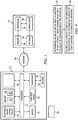
- Fig. 1 illustrates a schematic diagram of an apparatus 10 according to various embodiments of the invention and a server 12.
- the apparatus 10 includes a processor 14, a memory 16, a transceiver 18, one or more antennas 20, a user input device 22, a display 24, functional circuitry 26 and an electrical energy storage device 28.
- the apparatus 10 may be any device and may be a portable device (for example, a mobile cellular telephone, a personal digital assistant (PDA), a palmtop computer or a laptop computer), a non-portable device (for example, a desk top computer) or a module for such devices.
- a portable device for example, a mobile cellular telephone, a personal digital assistant (PDA), a palmtop computer or a laptop computer
- a non-portable device for example, a desk top computer
- 'module' refers to a unit or apparatus that excludes certain parts/components that would be added by an end manufacturer or a user. It should be appreciated that at least some of the features mentioned in the preceding paragraph may or may not be included in devices according to embodiments of the present invention.
- the processor 14 may be any suitable processor and may be a microprocessor for example. Implementation of the processor 14 can be in hardware alone (for example, a circuit, a processor and so on), have certain aspects in software including firmware alone or can be a combination of hardware and software (including firmware).
- the processor 14 may be implemented using instructions that enable hardware functionality, for example, by using executable computer program instructions in a general-purpose or special-purpose processor that may be stored on a computer readable storage medium (for example, a disk, a memory and so on) to be executed by such a processor.
- a general-purpose or special-purpose processor that may be stored on a computer readable storage medium (for example, a disk, a memory and so on) to be executed by such a processor.
- the processor 14 is configured to read from and write to the memory 16.
- the processor 14 may also comprise an output interface via which data and/or commands are output by the processor 14 and an input interface via which data and/or commands are input to the processor 14.
- the memory 16 may be any suitable memory and may, for example be permanent built-in memory such as flash memory or it may be a removable memory such as a hard disk, secure digital (SD) card or a micro-drive.
- the memory 16 stores a computer program 30 comprising computer program instructions that control the operation of the apparatus 10 when loaded into the processor 14.
- the computer program instructions 30 provide the logic and routines that enables the apparatus 10 to perform the methods illustrated in Figs. 2 , 4 , 5 and 6 .
- the processor 14 by reading the memory 16 is able to load and execute the computer program 30.
- the computer program may arrive at the apparatus 10 via any suitable delivery mechanism 32.
- the delivery mechanism 32 may be, for example, a computer-readable storage medium, a computer program product, a memory device, a record medium such as a Compact Disc (CD-ROM), a Digital Versatile Disc (DVD), a Blu-Ray disc, or any article of manufacture that tangibly embodies the computer program 30.
- the delivery mechanism 32 may be a signal configured to reliably transfer the computer program 30.
- the apparatus 10 may propagate or transmit the computer program 30 as a computer data signal.
- memory 16 is illustrated as a single component it may be implemented as one or more separate components some or all of which may be integrated/removable and/or may provide permanent/semi-permanent/ dynamic/cached storage.
- references to 'computer-readable storage medium', 'computer program product', 'tangibly embodied computer program' and so on, or a 'controller', 'computer', 'processor' and so on, should be understood to encompass not only computers having different architectures such as single /multi- processor architectures and sequential (Von Neumann)/parallel architectures but also specialized circuits such as field-programmable gate arrays (FPGA), application specific circuits (ASIC), signal processing devices and other devices.
- FPGA field-programmable gate arrays
- ASIC application specific circuits
- references to computer program, instructions, code and so on should be understood to encompass software for a programmable processor or firmware such as, for example, the programmable content of a hardware device whether instructions for a processor, or configuration settings for a fixed-function device, gate array or programmable logic device and so on.
- the transceiver 18 is connected to the antenna 20 and to the processor 14.
- the processor 14 is configured to provide data to the transceiver 18.
- the transceiver 18 is configured to encode the data and provide the encoded data to the antenna 20 for transmission.
- the antenna 20 is configured to transmit the encoded data as a radio signal.
- the antenna 20 is also configured to receive a radio signal.
- the transceiver 18 receives the radio signal from the antenna 20 and decodes the radio signal into data.
- the radio signal may have a frequency within a licensed cellular frequency band (for example, within a Global System for Mobile communications (GSM) frequency band (for example, 900 MHz)).
- GSM Global System for Mobile communications
- the user input device 22 (which may for example include one or more keys or a keypad) may be operable by a user to provide control signals to the processor 14.
- the user input device 22 may enable a user to control some or all aspects of a graphical user interface displayed on the display 24 of the apparatus 10.
- the display 24 is configured to receive and display data from the processor 14.
- the processor 14 may read data from the memory 16 and provide the data to the display 24 for display to a user of the apparatus 10.
- the display 24 may be any suitable display and may be, for example, a thin film transistor (TFT) display, a liquid crystal display (LCD) or a light emitting diode (LED) display (for example, an organic light emitting diode (OLED) display).
- TFT thin film transistor
- LCD liquid crystal display
- LED light emitting diode
- OLED organic light emitting diode
- the user input device 22 may be incorporated into the display to provide a touch screen display (for example, a resistive or a capacitive touch screen display).
- the display 24 may include one or more sensors (not illustrated) for sensing the application of force by a user and for providing a control signal to the processor 14.
- the processor 14 may be configured to control the display 24 using control signals received from the one or more sensors.
- the functional circuitry 26 includes other (optional) circuitry such as an audio input device (a microphone for example), an audio output device (a loudspeaker for example) and an imaging unit (including a charge coupled device (CCD) camera or a complementary metal oxide semiconductor (CMOS) camera).
- the functional circuitry 26 may also contain circuitry, such energy and power management circuitry that are used for monitoring and maintaining the electrical energy storage device 28.
- the electrical energy storage device 28 may be any device that is capable of storing electrical energy.
- the electrical energy storage device 12 may be a battery (a device that converts chemical energy to electrical energy) and may be, for example, a nickel cadmium (NiCd) battery, a nickel metal hydride (NiMH) battery, lithium-ion (Li-ion) battery, or a lithium ion polymer battery.
- the electrical energy storage device 28 may be, for example, a capacitor that is configured to store energy as electrical capacitance.
- the electrical energy storage device 28 may also contain circuitry to modify the electrical energy, for example to change the electrical voltage from one level to another. Further on, the electrical energy storage device 28 may also contain circuitry that allows the monitoring and maintenance of the electrical energy storage device 28, for example the battery voltage or the battery current. It should be understood that there may also exist several electrical energy storage devices 28.
- the apparatus 10 may include two or more batteries that may have different electrical energy characteristics (such as the amount of energy stored).
- the electrical energy storage device 28 is configured to supply electrical energy to the processor 14, the memory 16, the transceiver 18, the user input device 22, the display 24 and the functional circuitry 26 to enable them to function.
- the electrical energy storage device 28 may provide electrical energy to the display 24 so that a graphical user interface, images, videos and text may be displayed to a user of the apparatus 10. It should be understood that as the components of the apparatus 10 function, they drain energy from the electrical energy storage device 28 and reduce the electrical energy stored in the electrical energy storage device 28.
- the server 12 includes a processor 34, a memory 36, a transceiver 38 and an antenna 40.
- the processor 34, the memory 36, the transceiver 38 and the antenna 40 may be similar to the processor 14, the memory 16, the transceiver 18 and the antenna 20 respectively and will not be described in any further detail.
- the apparatus 10 and the server 12 are configured to communicate with one another via the network 42.
- the apparatus 10 and the server 12 may transmit data to one another via the network 42 and receive data from one another via the network 42.
- the network 42 may be any suitable network and may be a cellular network or the internet for example.
- the apparatus 10 has a plurality of configurations (which may also be referred to as 'profiles' or 'modes') which are defined by one or more user programmable apparatus settings.
- the user programmable apparatus settings control how one or more components of the apparatus 10 function and are substantially independent of any applications being executed by the processor 14.
- the setting of the user programmable apparatus settings is applied to the applications executed by the processor 14.
- a user may control the user input device 22 to program the user programmable apparatus settings to a desired setting and thus adapt an existing configuration or create a new configuration.
- One example of a user programmable apparatus setting is the brightness of a back light of the display 24.
- the user of the apparatus 10 may control the user input device 22 to change the brightness of the back light of the display 24 to a desired brightness level. That brightness level is then used for applications executed by the processor 14 (for example, a graphical user interface, an internet browser application, and gaming applications).
- FIG. 10 Another example of a user programmable apparatus setting is the audio output volume of a loud speaker 26 of the apparatus.
- the user of the apparatus 10 may control the user input device 22 to change the output volume of the loud speaker 26 to a desired level. That output volume is then used for applications executed by the processor 14.
- the apparatus 10 may be configured to scale the speed of a processor, such as clock frequency and voltage scaling, which trade energy consumption against the speed of execution at the processor.
- the apparatus 10 provides the apparatus 10 with a particular set of operating characteristics that may be useful for different contexts.
- the apparatus 10 may have a 'general profile' which is suitable for everyday use, and/or an 'outdoor profile' which is suitable for outdoor use, and/or a 'meeting profile' which is suitable for instances where the user would like the apparatus 10 to function in a discrete manner, and/or a 'maximum performance profile' and/or a 'maximum battery profile' which is set to minimize electrical energy consumption from the electrical energy storage device 28.
- the 'meeting profile' configuration provides a more discrete mode since the audio output volume is set to a low volume level or is set mute.
- the 'outdoor profile' is suitable for outdoors because the volume of audio output from the loudspeaker 26 is set high.
- the plurality of configurations of the apparatus 10 may use different amounts of electrical energy over a period of time.
- the 'meeting profile' configuration may use less electrical energy than the 'general profile' configuration because less electrical energy is supplied to the audio output device 26.
- the 'maximum battery profile' configuration may use less electrical energy than the other configurations because each of the user programmable apparatus settings are set to a level that consumes a minimal amount of electrical energy.
- the memory 16 stores a database 44 that includes values of one or more parameters of the electrical energy storage device 28 for a plurality of configurations of the apparatus 10.
- the value of a parameter is indicative of the usage of the electrical energy storage device 28 by the components of the apparatus 10.
- the parameters of the electrical energy storage device 28 may include (but are not limited to) remaining operating time of the apparatus 10 being powered by the electrical energy storage device 28, average power consumption of the electrical energy storage device 28 by the apparatus 10, maximum power consumption, minimum power consumption, median power consumption, the variance in power consumption and maximum capacity of the electrical energy storage device 28.
- the processor 14 is configured to measure (periodically or non-periodically) values of one or more of the parameters of the electrical energy storage device 28 for the configurations of the apparatus 10, and to store the measured values in the database 44.
- the processor 14 may use the circuitry of the electrical energy storage device 28 itself and/or the circuitry of the functional circuitry 26.
- the processor 14 may (periodically or non-periodically) measure the power consumption from the electrical energy device 28 and then determine the average power consumption taking the latest measurement into account for that particular configuration. The updated average power consumption is then stored in the database 44 for that configuration.
- the processor 14 may (periodically or non-periodically) measure, then determine and store the average power consumption from the electrical energy device 28 for that configuration.
- the processor 14 may determine the remaining operating time for some or all of the configurations by measuring the remaining electrical energy stored in the electrical energy storage device 28 and by then dividing the measured electrical energy by the average power consumptions of the configurations. The processor 14 then controls the storage of the calculated remaining operating times for the configurations in the database 44.
- the database 44 may also include values of one or more parameters of the electrical energy storage device 28 for one or more applications of the apparatus 10. For example, the database 44 may include the average power consumed by a web browser application. Additionally, the database 44 may include values of one or more parameters of the electrical energy storage device 28 for one or more user programmable apparatus settings. For example, the database 44 may include the average power consumed by the backlight of the display 24.
- the apparatus 10 is configured to perform a function using the values of the one or more parameters of the electrical energy storage device 28 stored in the database 44. This will be described in greater detail in the following paragraphs with reference to figs. 2 to 6 .
- Fig. 2 illustrates a flow diagram of a method according to various embodiments of the invention.
- the processor 14 determines values of one or more parameters of the electrical energy storage device 28 for a plurality of configurations of the apparatus 10.
- the processor 14 may read from the database 44 stored in the memory 16 to determine values of the one or more parameters.
- the processor 14 may read average power consumption values from the database 44 for a plurality of configurations.
- the processor 14 may read average power consumption values from the electrical energy storage device 28 or from the functional circuitry 26, if they include suitable circuitry.
- the processor 14 controls the display 24 to display the determined values of the one or more parameters of the electrical energy storage device 28 to a user of the apparatus 10. It should be appreciated that the display 24 may display any of the parameters mentioned above for a plurality of configurations.
- the processor 14 may control the display 24 to display the parameter values in response to a user request (for example, the user may select a user selectable object (an icon for example) of the graphical user interface to cause the display of the parameter values).
- the processor 14 may control the display 24 to display the remaining operating time for a plurality of configurations as illustrated in fig. 3A .
- the display 24 includes the text "General Profile - 220 H", “Meeting Profile - 225 H", “Max Performance - 150 H” and "Max battery - 300 H”.
- the processor 14 may control the display 24 to display the average power consumption for a plurality of configurations as illustrated in fig. 3B .
- the display 24 includes the text "General Profile - 30 mW", “Meeting Profile - 32 mW”, “Max Performance - 45 mW", "Max Battery - 15 mW”.
- the user may then operate the user input device 22 to select one of the configurations displayed on the display 24 to change the configuration of the apparatus 10. For example, if the user is aware that the electrical energy storage device 28 has a relatively low amount of electrical energy stored, he may select the "Max Battery" profile in order to increase the operating time of the apparatus 10.
- Embodiments of the present invention provide an advantage in that they enable a user to see how the different configurations/profiles of the apparatus 10 affect the electrical energy consumption from the electrical energy storage device 28. This may enable a user to make an informed choice of configuration/profile for the apparatus 10 and increase the time period between re-charging the electrical energy storage device 28.
- the processor 14 determines values of one or more parameters of the electrical energy storage device 28 for one or more user programmable apparatus settings.
- the processor 14 may read from the database 44 stored in the memory 16 to determine values of the one or more parameters. For example, the processor 14 may read an average power consumption value from the database 44 for a display brightness setting.
- the processor 14 then controls the display 24 to display the determined values of the one or more parameters of the electrical energy storage device 28 to a user of the apparatus 10.
- the processor 14 may control the display 24 to display the parameter values in response to a user request (for example, the user may select a user selectable object (an icon for example) of the graphical user interface to cause the display of the parameter values).
- the processor 14 may control the display 24 to display the average power consumption value for the backlight of the display and for the audio output device as illustrated in fig. 3C .
- the display 24 displays the text "Back Light - 270 mW” and "Audio Output - 500 mW”.
- Embodiments of the present invention provide an advantage in that they enable a user to see how the user programmable apparatus settings of the apparatus 10 affect the electrical energy consumption from the electrical energy storage device 28.
- the processor 14 determines values of one or more parameters of the electrical energy storage device 28 for one or more applications.
- the processor 14 may read from the database 44 stored in the memory 16 to determine values of the one or more parameters.
- the processor 14 may read an average power consumption value from the database 44 for a web browser application.
- the processor 14 then controls the display 24 to display the determined values of the one or more parameters of the electrical energy storage device 28 to a user of the apparatus 10.
- the processor 14 may control the display 24 to display the parameter values in response to a user request (for example, the user may select a user selectable object (an icon for example) of the graphical user interface to cause the display of the parameter values).
- the processor 14 may control the display 24 to display the average power consumption value for an e-mail application, a web browser application and a telephone application as illustrated in fig. 3D .
- the display 24 displays the text "E-mail - 75 mW", "Web Browsing - 350 mW” and "Telephone Call - 1220 mW”.
- Embodiments of the present invention provide an advantage in that they enable a user to see how the various applications of the apparatus 10 affect the electrical energy consumption from the electrical energy storage device 28.
- the processor 14 may be configured to control the display 24 to display the parameter values in other formats.
- the parameter values may be displayed as bars, plots, graphs and so on.
- the parameter values may be shown as non-numerical text, such as "You have enough battery energy left for the scheduled telephone conference in the afternoon".
- the processor 14 may access a user's schedule/diary stored in the memory 16, determine if the electrical energy device 28 includes sufficient electrical energy for the scheduled activities and then control the display 24 to display appropriate text.
- the database 44 may store parameters having various different units.
- the parameter values may have units such as Watts, Ampere hours, percentages and the remaining operating time may have units such as days, hours and minutes.
- Fig. 4 illustrates a flow diagram of another method according to various embodiments of the invention.
- the processor 14 determines values of one or more parameters of the electrical energy storage device 28 for a plurality of configurations of the apparatus 10.
- the processor 14 may read from the database 44 stored in the memory 16 to determine values of the one or more parameters. For example, the processor 14 may read average power consumption values or remaining operating times from the database 44 for a plurality of configurations.
- the processor 14 controls the display 24 to display a recommended configuration to a user of the apparatus 10, using the determined parameter values. For example, the processor 14 may determine that the remaining operating time is below a predetermined threshold (twenty five percent of capacity for example) and may then control the display 24 to display a message recommending that the configuration of the apparatus 10 be changed to a configuration that has lower power consumption (the 'Max Battery' configuration for example). The user may control the user input device 22 to select the recommended configuration and change the operating configuration of the apparatus 10.
- a predetermined threshold wenty five percent of capacity for example
- the user may control the user input device 22 to select the recommended configuration and change the operating configuration of the apparatus 10.
- Fig. 5 illustrates a flow diagram of a further method according to various embodiments of the invention.
- the processor 14 determines values of one or more parameters of the electrical energy storage device 28 for a plurality of configurations of the apparatus 10.
- the processor 14 may read from the database 44 stored in the memory 16 to determine values of the one or more parameters. For example, the processor 14 may read average power consumption values or remaining operating times from the database 44 for a plurality of configurations.
- the processor 14 uses the determined parameter values of the configurations to automatically change the configuration of the apparatus 10 without user intervention (that is, the user does not control the change in apparatus configuration). For example, the processor 14 may determine that the remaining operating time is below a predetermined threshold (twenty five percent of capacity for example), review the average power consumption values for the configurations, and may then automatically change the configuration of the apparatus 10 to a configuration that has lower average power consumption value (the 'Max Battery' configuration or the 'Meeting Profile' configuration for example).
- Fig. 6 illustrates a flow diagram of another method according to various embodiments of the invention. The method illustrated in fig. 6 flows from block 50 of the method illustrated in fig. 2 .
- the method includes enabling a user to program one or more of the user programmable apparatus settings to adapt an existing configuration and/or create a new configuration. For example, a user may review the average power consumption values for several user programmable apparatus settings in a particular configuration and notice that one of the settings (brightness of the display 24 for example) is set at a level that unnecessarily consumes a relatively large amount of electrical energy. The user may then lower the level of that setting (for example, reduce the brightness of the display 24) so that it consumes less electrical energy. The user may then save the adapted configuration over the previously saved configuration and/or save the configuration as a new configu ration.
- the processor 14 controls the transceiver 18 and the antenna 20 to transmit the adapted configuration and/or the created configuration to the server 12. It should be appreciated that the such a configuration may be transmitted also using any other data transfer means supported by the apparatus 10, such as Universal Serial Bus (USB), infrared communications, or even physical transfer using a removable memory (for example, a Multi Media Card (MMC), Secure Digital card (SD)). Block 64 may be executed automatically by the processor 14 or may be executed upon request by a user of the apparatus 10.
- USB Universal Serial Bus
- MMC Multi Media Card
- SD Secure Digital card
- the server 12 is configured to store the received configuration in the memory 36.
- Other apparatus (not illustrated in fig. 1 ) may request and download the configuration stored in the memory 36 of the server 12.
- Embodiments of the present invention provide an advantage in that the server may enable configurations to be shared between different apparatus. Since it may require a user to possess some technical knowledge/ability to adapt an existing configuration and/or create a new configuration, embodiments of the invention enable these configurations to be shared with user's who do not possess such technical knowledge/ability.
- competitions may be run for the most energy efficient configuration for a particular context (most energy efficient outdoor profile for example).
- Companies may also make configurations that are optimized for their employees or customers. For example, a shopping mall company may create a 'shopping mall' profile that assists customers to optimize their battery life while they are shopping in the shopping mall.
- the blocks illustrated in the Figs. 2 , 4 , 5 and 6 may represent steps in a method and/or sections of code in the computer program 30.
- the illustration of a particular order to the blocks does not necessarily imply that there is a required or preferred order for the blocks and the order and arrangement of the block may be varied. Furthermore, it may be possible for some steps to be omitted.
Landscapes
- Engineering & Computer Science (AREA)
- Computer Networks & Wireless Communication (AREA)
- Signal Processing (AREA)
- Physics & Mathematics (AREA)
- Electromagnetism (AREA)
- Databases & Information Systems (AREA)
- Charge And Discharge Circuits For Batteries Or The Like (AREA)
- Telephone Function (AREA)
- Power Sources (AREA)
- Control Of Electric Motors In General (AREA)
Description
- Embodiments of the present invention relate to apparatus, methods and computer programs. In particular, they relate to apparatus, methods and computer programs in a mobile cellular telephone.
- Apparatus, such as mobile cellular telephones, usually include an electrical energy storage device (a battery for example) for providing electrical energy to the electronic components of the apparatus. If the electrical energy stored in the electrical energy storage device falls below a threshold, the apparatus may become inoperable. This may be inconvenient for a user if they require the apparatus to be operable (to make a telephone call for example).
- It would therefore be desirable to provide an alternative apparatus.
-
DE10345437 discloses a method of securing the operation of a mobile phone by deactivation of applications in case of decreasing battery charge. Applications in user profiles are activated or deactivated in a series of operating systems, which are given or freely-selectable by the mobile radio unit user. The voltage sources for activation or deactivation of applications, are individually-determined as a function of the energy situation of the mobile radio unit. -
US 2007/0219732 discloses event triggered snapshots of display content of software application to facilitate a user, typically in the role of a software application developer, in the process of power-optimising an application under development. This provides the developers with an ability to correlate specific software application events, e.g. user interface events, to power consumption peaks and lows. - The present invention is as set out in the independent claims.
- According to various, but not necessarily all, implementation examples of the invention there is provided an apparatus according to
independent claim 10. The apparatus may be for monitoring an electrical energy storage device. - The function may include controlling a display to display the determined values of the one or more parameters of the electrical energy storage device to a user of the apparatus.
- The function may include controlling a display to display a recommended profile, selected from the plurality of profiles, to a user of the apparatus.
- The function may include controlling the apparatus to automatically enter a profile without user intervention.
- The at least one processor may be configured to execute the computer program instructions to cause the apparatus to further perform: determining values for a parameter of an electrical energy storage device for one or more user programmable apparatus settings, and controlling a display to display the determined parameter values for the one or more user programmable apparatus settings.
- The at least one processor may be configured to execute the computer program instructions to cause the apparatus to further perform: determining values of a parameter of an electrical energy storage device for one or more applications, and controlling a display to display the determined parameter values of the one or more applications.
- The at least one processor may be configured to execute the computer program instructions to cause the apparatus to further perform: enabling a user to program the user programmable apparatus settings to adapt an existing profile and/or to create a profile.
- The at least one processor may be configured to execute the computer program instructions to cause the apparatus to further perform: controlling a transmitter to transmit an adapted profile and/or a created profile to a server, the server being configured to transmit the adapted profile and/or the created profile to other apparatus.
- The parameter may be indicative of the usage of the electrical energy storage device by the apparatus.
- The parameter may include power consumption of the electrical energy storage device by the apparatus.
- The parameter may include remaining operating time of the apparatus being powered by the electrical energy storage device.
- The user programmable apparatus settings may be configured to control how one or more components of the apparatus function. The user programmable apparatus settings may be independent of any applications being executed by the at least one processor.
- According to various, but not necessarily all, implementation examples of the invention there is provided a method according to independent claim 1. The function may include controlling a display to display the determined values of the one or more parameters of the electrical energy storage device to a user of the apparatus.
- The function may include controlling a display to display a recommended profile, selected from the plurality of profiles, to a user of the apparatus.
- The function may include controlling the apparatus to automatically enter a profile without user intervention.
- The method may further comprise: determining values for a parameter of an electrical energy storage device for one or more user programmable apparatus settings, and controlling a display to display the determined parameter values for the one or more user programmable apparatus settings.
- The method may further comprise: determining a value of a parameter of an electrical energy storage device for one or more applications, and controlling a display to display the determined parameter values of the one or more applications.
- The method may further comprise: enabling a user to program the user programmable apparatus settings to adapt an existing profile and/or to create a profile.
- The at least one processor may be configured to execute the computer program instructions to cause the apparatus to further perform: controlling a transmitter to transmit an adapted profile and/or a created profile to a server, the server being configured to transmit the adapted profile and/or the created profile to other apparatus.
- The parameter may be indicative of the usage of the electrical energy storage device by the apparatus.
- The parameter may include power consumption of the electrical energy storage device by the apparatus.
- The parameter may include remaining operating time of the apparatus being powered by the electrical energy storage device.
- The user programmable apparatus settings may be configured to control how one or more components of the apparatus function. The user programmable apparatus settings may be independent of any applications being executed by the at least one processor.
- According to various, but not necessarily all, implementation examples of the invention there is provided a computer program that, when run on a computer, performs the method of independent claim 1. The function may include controlling a display to display the determined values of the one or more parameters of the electrical energy storage device to a user of the apparatus.
- The function may include controlling a display to display a recommended profile, selected from the plurality of profiles, to a user of the apparatus.
- The function may include controlling the apparatus to automatically enter a profile without user intervention.
- The user programmable apparatus settings may be configured to control how one or more components of the apparatus function. The user programmable apparatus settings may be independent of any applications being executed by the at least one processor.
- For a better understanding of various examples of implementation examples of the present invention reference will now be made by way of example only to the accompanying drawings in which:
-
Fig. 1 illustrates a schematic diagram of an apparatus according to various embodiments of the invention; -
Fig. 2 illustrates a flow diagram of a method according to various embodiments of the invention; -
Figs. 3A to 3D illustrate a front view of an apparatus according to various embodiments of the invention; -
Fig. 4 illustrates a flow diagram of another method according to various embodiments of the invention; -
Fig. 5 illustrates a flow diagram of a further method according to various embodiments of the invention; and -
Fig. 6 illustrates a flow diagram of another method according to various embodiments of the invention. - In the following description, the wording 'connect' and 'couple' and their derivatives mean operationally connected/coupled. It should be appreciated that any number or combination of intervening components can exist (including no intervening components).
-
Fig. 1 illustrates a schematic diagram of anapparatus 10 according to various embodiments of the invention and aserver 12. Theapparatus 10 includes aprocessor 14, amemory 16, atransceiver 18, one ormore antennas 20, auser input device 22, adisplay 24,functional circuitry 26 and an electricalenergy storage device 28. - The
apparatus 10 may be any device and may be a portable device (for example, a mobile cellular telephone, a personal digital assistant (PDA), a palmtop computer or a laptop computer), a non-portable device (for example, a desk top computer) or a module for such devices. As used here, 'module' refers to a unit or apparatus that excludes certain parts/components that would be added by an end manufacturer or a user. It should be appreciated that at least some of the features mentioned in the preceding paragraph may or may not be included in devices according to embodiments of the present invention. - The
processor 14 may be any suitable processor and may be a microprocessor for example. Implementation of theprocessor 14 can be in hardware alone (for example, a circuit, a processor and so on), have certain aspects in software including firmware alone or can be a combination of hardware and software (including firmware). - The
processor 14 may be implemented using instructions that enable hardware functionality, for example, by using executable computer program instructions in a general-purpose or special-purpose processor that may be stored on a computer readable storage medium (for example, a disk, a memory and so on) to be executed by such a processor. - The
processor 14 is configured to read from and write to thememory 16. Theprocessor 14 may also comprise an output interface via which data and/or commands are output by theprocessor 14 and an input interface via which data and/or commands are input to theprocessor 14. - The
memory 16 may be any suitable memory and may, for example be permanent built-in memory such as flash memory or it may be a removable memory such as a hard disk, secure digital (SD) card or a micro-drive. Thememory 16 stores acomputer program 30 comprising computer program instructions that control the operation of theapparatus 10 when loaded into theprocessor 14. Thecomputer program instructions 30 provide the logic and routines that enables theapparatus 10 to perform the methods illustrated inFigs. 2 ,4 ,5 and 6 . Theprocessor 14 by reading thememory 16 is able to load and execute thecomputer program 30. - The computer program may arrive at the
apparatus 10 via anysuitable delivery mechanism 32. Thedelivery mechanism 32 may be, for example, a computer-readable storage medium, a computer program product, a memory device, a record medium such as a Compact Disc (CD-ROM), a Digital Versatile Disc (DVD), a Blu-Ray disc, or any article of manufacture that tangibly embodies thecomputer program 30. Thedelivery mechanism 32 may be a signal configured to reliably transfer thecomputer program 30. Theapparatus 10 may propagate or transmit thecomputer program 30 as a computer data signal. - Although the
memory 16 is illustrated as a single component it may be implemented as one or more separate components some or all of which may be integrated/removable and/or may provide permanent/semi-permanent/ dynamic/cached storage. - References to 'computer-readable storage medium', 'computer program product', 'tangibly embodied computer program' and so on, or a 'controller', 'computer', 'processor' and so on, should be understood to encompass not only computers having different architectures such as single /multi- processor architectures and sequential (Von Neumann)/parallel architectures but also specialized circuits such as field-programmable gate arrays (FPGA), application specific circuits (ASIC), signal processing devices and other devices. References to computer program, instructions, code and so on should be understood to encompass software for a programmable processor or firmware such as, for example, the programmable content of a hardware device whether instructions for a processor, or configuration settings for a fixed-function device, gate array or programmable logic device and so on.
- The
transceiver 18 is connected to theantenna 20 and to theprocessor 14. Theprocessor 14 is configured to provide data to thetransceiver 18. Thetransceiver 18 is configured to encode the data and provide the encoded data to theantenna 20 for transmission. Theantenna 20 is configured to transmit the encoded data as a radio signal. Theantenna 20 is also configured to receive a radio signal. Thetransceiver 18 receives the radio signal from theantenna 20 and decodes the radio signal into data. The radio signal may have a frequency within a licensed cellular frequency band (for example, within a Global System for Mobile communications (GSM) frequency band (for example, 900 MHz)). - The user input device 22 (which may for example include one or more keys or a keypad) may be operable by a user to provide control signals to the
processor 14. Theuser input device 22 may enable a user to control some or all aspects of a graphical user interface displayed on thedisplay 24 of theapparatus 10. - The
display 24 is configured to receive and display data from theprocessor 14. Theprocessor 14 may read data from thememory 16 and provide the data to thedisplay 24 for display to a user of theapparatus 10. Thedisplay 24 may be any suitable display and may be, for example, a thin film transistor (TFT) display, a liquid crystal display (LCD) or a light emitting diode (LED) display (for example, an organic light emitting diode (OLED) display). - In some embodiments, the
user input device 22 may be incorporated into the display to provide a touch screen display (for example, a resistive or a capacitive touch screen display). Thedisplay 24 may include one or more sensors (not illustrated) for sensing the application of force by a user and for providing a control signal to theprocessor 14. Theprocessor 14 may be configured to control thedisplay 24 using control signals received from the one or more sensors. - The
functional circuitry 26 includes other (optional) circuitry such as an audio input device (a microphone for example), an audio output device (a loudspeaker for example) and an imaging unit (including a charge coupled device (CCD) camera or a complementary metal oxide semiconductor (CMOS) camera). Thefunctional circuitry 26 may also contain circuitry, such energy and power management circuitry that are used for monitoring and maintaining the electricalenergy storage device 28. - The electrical
energy storage device 28 may be any device that is capable of storing electrical energy. For example, the electricalenergy storage device 12 may be a battery (a device that converts chemical energy to electrical energy) and may be, for example, a nickel cadmium (NiCd) battery, a nickel metal hydride (NiMH) battery, lithium-ion (Li-ion) battery, or a lithium ion polymer battery. - Alternatively, the electrical
energy storage device 28 may be, for example, a capacitor that is configured to store energy as electrical capacitance. The electricalenergy storage device 28 may also contain circuitry to modify the electrical energy, for example to change the electrical voltage from one level to another. Further on, the electricalenergy storage device 28 may also contain circuitry that allows the monitoring and maintenance of the electricalenergy storage device 28, for example the battery voltage or the battery current. It should be understood that there may also exist several electricalenergy storage devices 28. For example, theapparatus 10 may include two or more batteries that may have different electrical energy characteristics (such as the amount of energy stored). - The electrical
energy storage device 28 is configured to supply electrical energy to theprocessor 14, thememory 16, thetransceiver 18, theuser input device 22, thedisplay 24 and thefunctional circuitry 26 to enable them to function. For example, the electricalenergy storage device 28 may provide electrical energy to thedisplay 24 so that a graphical user interface, images, videos and text may be displayed to a user of theapparatus 10. It should be understood that as the components of theapparatus 10 function, they drain energy from the electricalenergy storage device 28 and reduce the electrical energy stored in the electricalenergy storage device 28. - The
server 12 includes aprocessor 34, amemory 36, atransceiver 38 and anantenna 40. Theprocessor 34, thememory 36, thetransceiver 38 and theantenna 40 may be similar to theprocessor 14, thememory 16, thetransceiver 18 and theantenna 20 respectively and will not be described in any further detail. - The
apparatus 10 and theserver 12 are configured to communicate with one another via thenetwork 42. In particular, theapparatus 10 and theserver 12 may transmit data to one another via thenetwork 42 and receive data from one another via thenetwork 42. Thenetwork 42 may be any suitable network and may be a cellular network or the internet for example. - The
apparatus 10 has a plurality of configurations (which may also be referred to as 'profiles' or 'modes') which are defined by one or more user programmable apparatus settings. The user programmable apparatus settings control how one or more components of theapparatus 10 function and are substantially independent of any applications being executed by theprocessor 14. The setting of the user programmable apparatus settings is applied to the applications executed by theprocessor 14. A user may control theuser input device 22 to program the user programmable apparatus settings to a desired setting and thus adapt an existing configuration or create a new configuration. - One example of a user programmable apparatus setting is the brightness of a back light of the
display 24. The user of theapparatus 10 may control theuser input device 22 to change the brightness of the back light of thedisplay 24 to a desired brightness level. That brightness level is then used for applications executed by the processor 14 (for example, a graphical user interface, an internet browser application, and gaming applications). - Another example of a user programmable apparatus setting is the audio output volume of a
loud speaker 26 of the apparatus. The user of theapparatus 10 may control theuser input device 22 to change the output volume of theloud speaker 26 to a desired level. That output volume is then used for applications executed by theprocessor 14. - Yet another example of a user programmable apparatus setting is the speed of processing at the
processor 14. For example, theapparatus 10 may be configured to scale the speed of a processor, such as clock frequency and voltage scaling, which trade energy consumption against the speed of execution at the processor. - It should be understood that a configuration of the
apparatus 10 provides theapparatus 10 with a particular set of operating characteristics that may be useful for different contexts. For example, theapparatus 10 may have a 'general profile' which is suitable for everyday use, and/or an 'outdoor profile' which is suitable for outdoor use, and/or a 'meeting profile' which is suitable for instances where the user would like theapparatus 10 to function in a discrete manner, and/or a 'maximum performance profile' and/or a 'maximum battery profile' which is set to minimize electrical energy consumption from the electricalenergy storage device 28. By way of an example, the 'meeting profile' configuration provides a more discrete mode since the audio output volume is set to a low volume level or is set mute. By way of a further example, the 'outdoor profile' is suitable for outdoors because the volume of audio output from theloudspeaker 26 is set high. - It should be appreciated that the plurality of configurations of the
apparatus 10 may use different amounts of electrical energy over a period of time. For example, the 'meeting profile' configuration may use less electrical energy than the 'general profile' configuration because less electrical energy is supplied to theaudio output device 26. By way of a further example, the 'maximum battery profile' configuration may use less electrical energy than the other configurations because each of the user programmable apparatus settings are set to a level that consumes a minimal amount of electrical energy. - The
memory 16 stores adatabase 44 that includes values of one or more parameters of the electricalenergy storage device 28 for a plurality of configurations of theapparatus 10. The value of a parameter is indicative of the usage of the electricalenergy storage device 28 by the components of theapparatus 10. The parameters of the electricalenergy storage device 28 may include (but are not limited to) remaining operating time of theapparatus 10 being powered by the electricalenergy storage device 28, average power consumption of the electricalenergy storage device 28 by theapparatus 10, maximum power consumption, minimum power consumption, median power consumption, the variance in power consumption and maximum capacity of the electricalenergy storage device 28. - The
processor 14 is configured to measure (periodically or non-periodically) values of one or more of the parameters of the electricalenergy storage device 28 for the configurations of theapparatus 10, and to store the measured values in thedatabase 44. When executing these actions, theprocessor 14 may use the circuitry of the electricalenergy storage device 28 itself and/or the circuitry of thefunctional circuitry 26. For example, when theapparatus 10 is in a configuration, theprocessor 14 may (periodically or non-periodically) measure the power consumption from theelectrical energy device 28 and then determine the average power consumption taking the latest measurement into account for that particular configuration. The updated average power consumption is then stored in thedatabase 44 for that configuration. When theapparatus 10 enters another configuration, theprocessor 14 may (periodically or non-periodically) measure, then determine and store the average power consumption from theelectrical energy device 28 for that configuration. - By way of another example, the
processor 14 may determine the remaining operating time for some or all of the configurations by measuring the remaining electrical energy stored in the electricalenergy storage device 28 and by then dividing the measured electrical energy by the average power consumptions of the configurations. Theprocessor 14 then controls the storage of the calculated remaining operating times for the configurations in thedatabase 44. - The
database 44 may also include values of one or more parameters of the electricalenergy storage device 28 for one or more applications of theapparatus 10. For example, thedatabase 44 may include the average power consumed by a web browser application. Additionally, thedatabase 44 may include values of one or more parameters of the electricalenergy storage device 28 for one or more user programmable apparatus settings. For example, thedatabase 44 may include the average power consumed by the backlight of thedisplay 24. - The
apparatus 10 is configured to perform a function using the values of the one or more parameters of the electricalenergy storage device 28 stored in thedatabase 44. This will be described in greater detail in the following paragraphs with reference tofigs. 2 to 6 . -
Fig. 2 illustrates a flow diagram of a method according to various embodiments of the invention. Atblock 46, theprocessor 14 determines values of one or more parameters of the electricalenergy storage device 28 for a plurality of configurations of theapparatus 10. Theprocessor 14 may read from thedatabase 44 stored in thememory 16 to determine values of the one or more parameters. For example, theprocessor 14 may read average power consumption values from thedatabase 44 for a plurality of configurations. Alternatively, theprocessor 14 may read average power consumption values from the electricalenergy storage device 28 or from thefunctional circuitry 26, if they include suitable circuitry. - At
block 48, theprocessor 14 controls thedisplay 24 to display the determined values of the one or more parameters of the electricalenergy storage device 28 to a user of theapparatus 10. It should be appreciated that thedisplay 24 may display any of the parameters mentioned above for a plurality of configurations. Theprocessor 14 may control thedisplay 24 to display the parameter values in response to a user request (for example, the user may select a user selectable object (an icon for example) of the graphical user interface to cause the display of the parameter values). - For example, the
processor 14 may control thedisplay 24 to display the remaining operating time for a plurality of configurations as illustrated infig. 3A . Infig. 3A , thedisplay 24 includes the text "General Profile - 220 H", "Meeting Profile - 225 H", "Max Performance - 150 H" and "Max battery - 300 H". By way of a further example, theprocessor 14 may control thedisplay 24 to display the average power consumption for a plurality of configurations as illustrated infig. 3B . Infig. 3B , thedisplay 24 includes the text "General Profile - 30 mW", "Meeting Profile - 32 mW", "Max Performance - 45 mW", "Max Battery - 15 mW". - The user may then operate the
user input device 22 to select one of the configurations displayed on thedisplay 24 to change the configuration of theapparatus 10. For example, if the user is aware that the electricalenergy storage device 28 has a relatively low amount of electrical energy stored, he may select the "Max Battery" profile in order to increase the operating time of theapparatus 10. - Embodiments of the present invention provide an advantage in that they enable a user to see how the different configurations/profiles of the
apparatus 10 affect the electrical energy consumption from the electricalenergy storage device 28. This may enable a user to make an informed choice of configuration/profile for theapparatus 10 and increase the time period between re-charging the electricalenergy storage device 28. - At
block 50, theprocessor 14 determines values of one or more parameters of the electricalenergy storage device 28 for one or more user programmable apparatus settings. Theprocessor 14 may read from thedatabase 44 stored in thememory 16 to determine values of the one or more parameters. For example, theprocessor 14 may read an average power consumption value from thedatabase 44 for a display brightness setting. - The
processor 14 then controls thedisplay 24 to display the determined values of the one or more parameters of the electricalenergy storage device 28 to a user of theapparatus 10. Theprocessor 14 may control thedisplay 24 to display the parameter values in response to a user request (for example, the user may select a user selectable object (an icon for example) of the graphical user interface to cause the display of the parameter values). - For example, the
processor 14 may control thedisplay 24 to display the average power consumption value for the backlight of the display and for the audio output device as illustrated infig. 3C . Infig. 3C , thedisplay 24 displays the text "Back Light - 270 mW" and "Audio Output - 500 mW". - Embodiments of the present invention provide an advantage in that they enable a user to see how the user programmable apparatus settings of the
apparatus 10 affect the electrical energy consumption from the electricalenergy storage device 28. - At
block 52, theprocessor 14 determines values of one or more parameters of the electricalenergy storage device 28 for one or more applications. Theprocessor 14 may read from thedatabase 44 stored in thememory 16 to determine values of the one or more parameters. For example, theprocessor 14 may read an average power consumption value from thedatabase 44 for a web browser application. - The
processor 14 then controls thedisplay 24 to display the determined values of the one or more parameters of the electricalenergy storage device 28 to a user of theapparatus 10. Theprocessor 14 may control thedisplay 24 to display the parameter values in response to a user request (for example, the user may select a user selectable object (an icon for example) of the graphical user interface to cause the display of the parameter values). - For example, the
processor 14 may control thedisplay 24 to display the average power consumption value for an e-mail application, a web browser application and a telephone application as illustrated infig. 3D . Infig. 3D , thedisplay 24 displays the text "E-mail - 75 mW", "Web Browsing - 350 mW" and "Telephone Call - 1220 mW". - Embodiments of the present invention provide an advantage in that they enable a user to see how the various applications of the
apparatus 10 affect the electrical energy consumption from the electricalenergy storage device 28. - It should be appreciated that the
processor 14 may be configured to control thedisplay 24 to display the parameter values in other formats. For example, the parameter values may be displayed as bars, plots, graphs and so on. In addition, the parameter values may be shown as non-numerical text, such as "You have enough battery energy left for the scheduled telephone conference in the afternoon". In order to display such text, theprocessor 14 may access a user's schedule/diary stored in thememory 16, determine if theelectrical energy device 28 includes sufficient electrical energy for the scheduled activities and then control thedisplay 24 to display appropriate text. Furthermore, thedatabase 44 may store parameters having various different units. For example, the parameter values may have units such as Watts, Ampere hours, percentages and the remaining operating time may have units such as days, hours and minutes. -
Fig. 4 illustrates a flow diagram of another method according to various embodiments of the invention. Atblock 54, theprocessor 14 determines values of one or more parameters of the electricalenergy storage device 28 for a plurality of configurations of theapparatus 10. Theprocessor 14 may read from thedatabase 44 stored in thememory 16 to determine values of the one or more parameters. For example, theprocessor 14 may read average power consumption values or remaining operating times from thedatabase 44 for a plurality of configurations. - At
block 56, theprocessor 14 controls thedisplay 24 to display a recommended configuration to a user of theapparatus 10, using the determined parameter values. For example, theprocessor 14 may determine that the remaining operating time is below a predetermined threshold (twenty five percent of capacity for example) and may then control thedisplay 24 to display a message recommending that the configuration of theapparatus 10 be changed to a configuration that has lower power consumption (the 'Max Battery' configuration for example). The user may control theuser input device 22 to select the recommended configuration and change the operating configuration of theapparatus 10. -
Fig. 5 illustrates a flow diagram of a further method according to various embodiments of the invention. Atblock 58, theprocessor 14 determines values of one or more parameters of the electricalenergy storage device 28 for a plurality of configurations of theapparatus 10. Theprocessor 14 may read from thedatabase 44 stored in thememory 16 to determine values of the one or more parameters. For example, theprocessor 14 may read average power consumption values or remaining operating times from thedatabase 44 for a plurality of configurations. - At
block 60, theprocessor 14 uses the determined parameter values of the configurations to automatically change the configuration of theapparatus 10 without user intervention (that is, the user does not control the change in apparatus configuration). For example, theprocessor 14 may determine that the remaining operating time is below a predetermined threshold (twenty five percent of capacity for example), review the average power consumption values for the configurations, and may then automatically change the configuration of theapparatus 10 to a configuration that has lower average power consumption value (the 'Max Battery' configuration or the 'Meeting Profile' configuration for example). -
Fig. 6 illustrates a flow diagram of another method according to various embodiments of the invention. The method illustrated infig. 6 flows fromblock 50 of the method illustrated infig. 2 . - At
block 62, the method includes enabling a user to program one or more of the user programmable apparatus settings to adapt an existing configuration and/or create a new configuration. For example, a user may review the average power consumption values for several user programmable apparatus settings in a particular configuration and notice that one of the settings (brightness of thedisplay 24 for example) is set at a level that unnecessarily consumes a relatively large amount of electrical energy. The user may then lower the level of that setting (for example, reduce the brightness of the display 24) so that it consumes less electrical energy. The user may then save the adapted configuration over the previously saved configuration and/or save the configuration as a new configu ration. - At
block 64, theprocessor 14 controls thetransceiver 18 and theantenna 20 to transmit the adapted configuration and/or the created configuration to theserver 12. It should be appreciated that the such a configuration may be transmitted also using any other data transfer means supported by theapparatus 10, such as Universal Serial Bus (USB), infrared communications, or even physical transfer using a removable memory (for example, a Multi Media Card (MMC), Secure Digital card (SD)).Block 64 may be executed automatically by theprocessor 14 or may be executed upon request by a user of theapparatus 10. - The
server 12 is configured to store the received configuration in thememory 36. Other apparatus (not illustrated infig. 1 ) may request and download the configuration stored in thememory 36 of theserver 12. - Embodiments of the present invention provide an advantage in that the server may enable configurations to be shared between different apparatus. Since it may require a user to possess some technical knowledge/ability to adapt an existing configuration and/or create a new configuration, embodiments of the invention enable these configurations to be shared with user's who do not possess such technical knowledge/ability. As an incentive to encourage users to upload configurations to the
server 12, competitions may be run for the most energy efficient configuration for a particular context (most energy efficient outdoor profile for example). Companies may also make configurations that are optimized for their employees or customers. For example, a shopping mall company may create a 'shopping mall' profile that assists customers to optimize their battery life while they are shopping in the shopping mall. - The blocks illustrated in the
Figs. 2 ,4 ,5 and 6 may represent steps in a method and/or sections of code in thecomputer program 30. The illustration of a particular order to the blocks does not necessarily imply that there is a required or preferred order for the blocks and the order and arrangement of the block may be varied. Furthermore, it may be possible for some steps to be omitted. - Although embodiments of the present invention have been described in the preceding paragraphs with reference to various examples, it should be appreciated that modifications to the examples given can be made without departing from the scope of the invention as claimed.
- Features described in the preceding description may be used in combinations other than the combinations explicitly described.
- Although functions have been described with reference to certain features, those functions may be performable by other features whether described or not.
- Although features have been described with reference to certain embodiments, those features may also be present in other embodiments whether described or not.
- Whilst endeavoring in the foregoing specification to draw attention to those features of the invention believed to be of particular importance it should be understood that the Applicant claims protection in respect of any patentable feature or combination of features hereinbefore referred to and/or shown in the drawings whether or not particular emphasis has been placed thereon.
Claims (13)
- A method comprising:determining values of one or more parameters of an electrical energy storage device (28) for a plurality of configurations of an apparatus (10), the plurality of configurations being defined by one or more user programmable apparatus settings;performing a function using the determined values of the one or more parameters of the electrical energy storage device (28);determining values of one or more parameters of an electrical energy storage device (28) for each of a plurality of applications, andcontrolling a display (24) to display the determined parameter values for each of the plurality of applications simultaneously, wherein the display (24) of the determined parameter values for each of the plurality of applications is controlled to show how each of the plurality of applications of the apparatus (10) affect the electrical energy consumption from the electrical energy storage device (28).
- A method as claimed in claim 1, wherein the display (24) of the determined parameter values of each of the plurality of applications is controlled to indicate power consumption values for each of the plurality of applications.
- A method as claimed in claim 1 or 2, wherein the plurality of configurations of the apparatus (10) comprises:a plurality of profiles of the apparatus (10), the plurality of profiles defined by one or more user programmable apparatus settings, ora plurality of programmable apparatus settings of the apparatus (10).
- A method as claimed in any preceding claim, further comprising receiving a user selection of one of the displayed determined parameter values of the plurality of profiles.
- A method as claimed in claim 1, wherein the plurality of configurations comprises a plurality of profiles, and wherein the function includes controlling a display (24) to display a recommended profile, selected from the plurality of profiles, to a user of the apparatus (10).
- A method as claimed in any preceding claim, wherein the plurality of configurations comprises a plurality of profiles, and wherein the function includes controlling the apparatus (10) to automatically enter a profile without user intervention.
- A method as claimed in any preceding claim, wherein the plurality of configurations comprises a plurality of user programmable apparatus settings, the method further comprising: enabling a user to program the user programmable apparatus settings to adapt an existing profile and/or to create a profile.
- A method as claimed in any preceding claim, wherein at least one of:the parameter is indicative of the usage of the electrical energy storage device (28) by the apparatus (10),the parameter includes power consumption of the electrical energy storage device (28) by the apparatus (10), andparameter includes remaining operating time of the apparatus (10) being powered by the electrical energy storage device (28).
- A method as claimed in any preceding claim, wherein the plurality of configurations comprises a plurality of user programmable apparatus settings, and wherein the user programmable apparatus settings are configured to control how one or more components of the apparatus function and are independent of any applications being executed by the at least one processor.
- An apparatus (10) comprising:means (14, 16) configured to determine values of one or more parameters of an electrical energy storage device (28) for a plurality of configurations of the apparatus (10), the plurality of configurations being defined by one or more user programmable apparatus settings;means (14, 16) configured to perform a function using the determined values of the one or more parameters of the electrical energy storage device (28);means (14, 16) configured to determine values of one or more parameters of an electrical energy storage device (28) for each of a plurality of applications, andmeans (14, 16) configured to control a display (24) to display the determined parameter values for each of the plurality of applications simultaneously, wherein the display (24) of the determined parameter values for each of the plurality of applications is controlled to show how each of the plurality of applications of the apparatus (10) affect the electrical energy consumption from the electrical energy storage device (28).
- An apparatus as claimed in claim 10, wherein said means comprise:at least one memory (16) storing computer program instructions; andat least one processor (14) configured to execute the computer program instructions to cause the apparatus to perform the method as claimed in any one of claims 1 to 9.
- An apparatus as claimed in claim 11 or 12, wherein the apparatus is a portable communication device.
- A computer program (30) that, when run on a computer (10), is configured to cause the computer to perform the method as claimed in any one of claims 1 to 9.
Applications Claiming Priority (2)
| Application Number | Priority Date | Filing Date | Title |
|---|---|---|---|
| GBGB1005328.8A GB201005328D0 (en) | 2010-03-30 | 2010-03-30 | Apparatus, methods, computer readable storage mediums and computer programs |
| PCT/FI2011/050082 WO2011121170A1 (en) | 2010-03-30 | 2011-02-01 | Apparatus, methods, computer readable storage mediums and computer programs |
Publications (3)
| Publication Number | Publication Date |
|---|---|
| EP2553478A1 EP2553478A1 (en) | 2013-02-06 |
| EP2553478A4 EP2553478A4 (en) | 2013-09-25 |
| EP2553478B1 true EP2553478B1 (en) | 2018-05-23 |
Family
ID=42228590
Family Applications (1)
| Application Number | Title | Priority Date | Filing Date |
|---|---|---|---|
| EP11762065.8A Active EP2553478B1 (en) | 2010-03-30 | 2011-02-01 | Apparatus, methods, computer readable storage mediums and computer programs |
Country Status (6)
| Country | Link |
|---|---|
| US (1) | US9380447B2 (en) |
| EP (1) | EP2553478B1 (en) |
| CN (1) | CN102918405B (en) |
| GB (1) | GB201005328D0 (en) |
| RU (1) | RU2543571C2 (en) |
| WO (1) | WO2011121170A1 (en) |
Families Citing this family (5)
| Publication number | Priority date | Publication date | Assignee | Title |
|---|---|---|---|---|
| WO2014034196A1 (en) * | 2012-08-29 | 2014-03-06 | ソニー株式会社 | Communication device, communication control device, program, and communication control method |
| US9292067B2 (en) * | 2013-06-04 | 2016-03-22 | Qualcomm Incorporated | System and method for managing rechargeable power sources in a portable computing device with two or more usage modes |
| CN106550390A (en) * | 2015-09-22 | 2017-03-29 | 中兴通讯股份有限公司 | A kind of power consumption method for detecting abnormality and device |
| CN109448252A (en) * | 2018-09-27 | 2019-03-08 | 宁波三星智能电气有限公司 | A kind of method of real-time setting CIU Rotation Item |
| US20230362810A1 (en) * | 2022-05-09 | 2023-11-09 | Qualcomm Incorporated | Power consumption calculation and reporting |
Family Cites Families (29)
| Publication number | Priority date | Publication date | Assignee | Title |
|---|---|---|---|---|
| US5958058A (en) | 1997-07-18 | 1999-09-28 | Micron Electronics, Inc. | User-selectable power management interface with application threshold warnings |
| US6433512B1 (en) * | 1999-01-27 | 2002-08-13 | Telefonaktebolaget L M Ericsson (Publ) | Power consumption reporting by an accessory of an electronic device |
| JP2001255967A (en) | 2000-03-13 | 2001-09-21 | Toshiba Corp | Information processing apparatus and power control method thereof |
| GB2373886A (en) | 2001-03-28 | 2002-10-02 | Hewlett Packard Co | User selectable power management of software applications |
| US20020142792A1 (en) * | 2001-04-03 | 2002-10-03 | Telefonaktiebolaget L M Ericsson(Publ) | Method and apparatus for automated selection of user preference information |
| KR100417407B1 (en) | 2001-05-25 | 2004-02-05 | 엘지전자 주식회사 | Power saving method of mobile communication terminal |
| US20030158609A1 (en) * | 2002-02-19 | 2003-08-21 | Koninklijke Philips Electronics N.V. | Power saving management for portable devices |
| CN100498364C (en) | 2002-09-24 | 2009-06-10 | 捷讯研究有限公司 | System and method of battery capacity estimation |
| US20040122949A1 (en) * | 2002-12-23 | 2004-06-24 | Zmudzinski Krystof C. | System and method for browsing on behalf of others |
| GB2397972A (en) | 2003-01-29 | 2004-08-04 | Nec Technologies | Power saving in a foldable portable communication device |
| US8392655B2 (en) * | 2003-09-30 | 2013-03-05 | Lenovo (Singapore) Pte Ltd. | Apparatus for reducing accesses to levels of a storage hierarchy in a computing system |
| DE10345437A1 (en) * | 2003-09-30 | 2005-05-19 | Siemens Ag | Method for operating a mobile radio terminal with an operating system |
| WO2006030368A2 (en) | 2004-09-17 | 2006-03-23 | Koninklijke Philips Electronics N.V. | Updating prioritizing related to data retention using volatile memories |
| US20060095864A1 (en) | 2004-11-04 | 2006-05-04 | Motorola, Inc. | Method and system for representing an application characteristic using a sensory perceptible representation |
| US7881708B2 (en) * | 2004-12-27 | 2011-02-01 | Nokia Corporation | Mobile terminal, and an associated method, with means for modifying a behavior pattern of a multi-medial user interface |
| US7552349B2 (en) | 2005-03-07 | 2009-06-23 | Microsoft Corporation | User configurable power conservation through LCD display screen reduction |
| RU54703U1 (en) * | 2005-10-31 | 2006-07-10 | Сергей Александрович Мосиенко | MOBILE PHONE BACKUP DEVICE (OPTIONS) |
| TWI274891B (en) | 2006-01-17 | 2007-03-01 | Benq Corp | Systems, methods and machine-readable storage media for battery power management of electronic systems |
| US9407747B2 (en) | 2006-03-14 | 2016-08-02 | Nokia Technologies Oy | Mobile device and method |
| US7598702B2 (en) | 2006-04-27 | 2009-10-06 | Hewlett-Packard Development Company, L.P. | Power management system and method for controlling use of power-consuming applications |
| US7616882B2 (en) | 2006-08-10 | 2009-11-10 | Research In Motion Limited | Method and apparatus for power management in an electronic device |
| KR101105772B1 (en) | 2006-10-27 | 2012-01-17 | 엘지전자 주식회사 | Broadcast receiving terminal and operation control method |
| US20080200220A1 (en) | 2007-02-16 | 2008-08-21 | Jackson Bruce K | Methods and devices for limiting battery power consumption in a wireless communication device |
| GB2448534B (en) | 2007-04-19 | 2009-11-18 | Vodafone Plc | Mobile telecommunications device |
| EP2023682A1 (en) | 2007-06-25 | 2009-02-11 | Nederlandse Organisatie voor toegepast- natuurwetenschappelijk onderzoek TNO | Method and system for predicting the power consumption of a mobile terminal |
| US7957775B2 (en) | 2007-11-05 | 2011-06-07 | International Business Machines Corporation | Low battery notification service for wireless device users |
| US20090164152A1 (en) | 2007-12-20 | 2009-06-25 | Nokia Corporation | Method, Apparatus and Computer Program Product for Providing Power Consumption Notification and Management |
| US8423306B2 (en) | 2008-05-22 | 2013-04-16 | Microsoft Corporation | Battery detection and user experience |
| JP5074557B2 (en) | 2010-06-09 | 2012-11-14 | 日本電信電話株式会社 | Data distribution system and data distribution method |
-
2010
- 2010-03-30 GB GBGB1005328.8A patent/GB201005328D0/en not_active Ceased
-
2011
- 2011-02-01 RU RU2012144774/08A patent/RU2543571C2/en active
- 2011-02-01 CN CN201180026670.5A patent/CN102918405B/en active Active
- 2011-02-01 WO PCT/FI2011/050082 patent/WO2011121170A1/en not_active Ceased
- 2011-02-01 EP EP11762065.8A patent/EP2553478B1/en active Active
- 2011-02-01 US US13/637,492 patent/US9380447B2/en active Active
Also Published As
| Publication number | Publication date |
|---|---|
| EP2553478A4 (en) | 2013-09-25 |
| CN102918405A (en) | 2013-02-06 |
| RU2543571C2 (en) | 2015-03-10 |
| US9380447B2 (en) | 2016-06-28 |
| US20140349717A1 (en) | 2014-11-27 |
| GB201005328D0 (en) | 2010-05-12 |
| EP2553478A1 (en) | 2013-02-06 |
| RU2012144774A (en) | 2014-05-10 |
| WO2011121170A1 (en) | 2011-10-06 |
| CN102918405B (en) | 2016-03-09 |
Similar Documents
| Publication | Publication Date | Title |
|---|---|---|
| CN110225167B (en) | Terminal and processing method | |
| CN112074006B (en) | Power Sensitive Wireless Communications Radio Management | |
| KR102336856B1 (en) | Method for Controlling of Charging/Discharging Battery and Electronic Device Using the same | |
| CN105573465B (en) | Electronic device and method of controlling power of electronic device | |
| CN105930207B (en) | Electronic device and application control method thereof | |
| US20190205187A1 (en) | System and methods for launching an application on an electronic device | |
| CN109361818A (en) | Charging reminding method, device, storage medium and terminal | |
| CN106663362A (en) | Method for providing user with battery power notification on mobile device and mobile device thereof | |
| US9609600B2 (en) | Wireless communication system with enhanced power management | |
| CN108241422A (en) | Electronic equipment and the heat control method based on the battery temperature in electronic equipment | |
| US20120221877A1 (en) | Method and apparatus for managing power levels in a handheld mobile communication device | |
| CN110429696B (en) | Battery charging method, electronic device and computer readable storage medium | |
| KR102151135B1 (en) | Method for managing power and electronic device thereof | |
| CN108702421A (en) | Electronic device and method for controlling applications and components | |
| CN106095038A (en) | For preventing method and the electronic equipment thereof of cell expansion | |
| US9380447B2 (en) | Apparatus, methods, computer readable storage mediums and computer programs | |
| US20140245041A1 (en) | Apparatus for hibernation control in a device | |
| CN105303361B (en) | Alarm clock adjusting method and device and terminal | |
| CN111464690A (en) | Application preloading method and electronic device | |
| US20150113301A1 (en) | Charging method and mobile electronic device | |
| CN108616653A (en) | Information processing method, device, mobile terminal and computer readable storage medium | |
| US20130132750A1 (en) | Electronic device and method for updating a time identifier associated therewith | |
| CN108549593A (en) | Information processing method, device, mobile terminal and computer readable storage medium | |
| CN104348949A (en) | Method and apparatus for switching operation state of electronic device | |
| CN108834206A (en) | Electronic device control method and electronic device |
Legal Events
| Date | Code | Title | Description |
|---|---|---|---|
| PUAI | Public reference made under article 153(3) epc to a published international application that has entered the european phase |
Free format text: ORIGINAL CODE: 0009012 |
|
| 17P | Request for examination filed |
Effective date: 20120920 |
|
| AK | Designated contracting states |
Kind code of ref document: A1 Designated state(s): AL AT BE BG CH CY CZ DE DK EE ES FI FR GB GR HR HU IE IS IT LI LT LU LV MC MK MT NL NO PL PT RO RS SE SI SK SM TR |
|
| DAX | Request for extension of the european patent (deleted) | ||
| A4 | Supplementary search report drawn up and despatched |
Effective date: 20130827 |
|
| RIC1 | Information provided on ipc code assigned before grant |
Ipc: H04W 52/28 20090101ALI20130821BHEP Ipc: H04W 52/02 20090101ALI20130821BHEP Ipc: H04B 17/00 20060101ALI20130821BHEP Ipc: G01R 31/36 20060101ALN20130821BHEP Ipc: H02J 7/00 20060101ALI20130821BHEP Ipc: G01R 22/06 20060101AFI20130821BHEP Ipc: H04W 52/00 20090101ALI20130821BHEP |
|
| RAP1 | Party data changed (applicant data changed or rights of an application transferred) |
Owner name: NOKIA CORPORATION |
|
| RAP1 | Party data changed (applicant data changed or rights of an application transferred) |
Owner name: NOKIA TECHNOLOGIES OY |
|
| 17Q | First examination report despatched |
Effective date: 20151106 |
|
| GRAP | Despatch of communication of intention to grant a patent |
Free format text: ORIGINAL CODE: EPIDOSNIGR1 |
|
| STAA | Information on the status of an ep patent application or granted ep patent |
Free format text: STATUS: GRANT OF PATENT IS INTENDED |
|
| RIC1 | Information provided on ipc code assigned before grant |
Ipc: G01R 22/06 20060101AFI20171204BHEP Ipc: H04W 52/02 20090101ALI20171204BHEP Ipc: H04W 52/00 20090101ALI20171204BHEP Ipc: G01R 31/36 20060101ALN20171204BHEP Ipc: H04B 17/00 20150101ALI20171204BHEP Ipc: H04W 52/28 20090101ALI20171204BHEP Ipc: H02J 7/00 20060101ALI20171204BHEP |
|
| INTG | Intention to grant announced |
Effective date: 20171221 |
|
| GRAS | Grant fee paid |
Free format text: ORIGINAL CODE: EPIDOSNIGR3 |
|
| GRAA | (expected) grant |
Free format text: ORIGINAL CODE: 0009210 |
|
| STAA | Information on the status of an ep patent application or granted ep patent |
Free format text: STATUS: THE PATENT HAS BEEN GRANTED |
|
| AK | Designated contracting states |
Kind code of ref document: B1 Designated state(s): AL AT BE BG CH CY CZ DE DK EE ES FI FR GB GR HR HU IE IS IT LI LT LU LV MC MK MT NL NO PL PT RO RS SE SI SK SM TR |
|
| REG | Reference to a national code |
Ref country code: GB Ref legal event code: FG4D |
|
| REG | Reference to a national code |
Ref country code: CH Ref legal event code: EP |
|
| REG | Reference to a national code |
Ref country code: IE Ref legal event code: FG4D |
|
| REG | Reference to a national code |
Ref country code: AT Ref legal event code: REF Ref document number: 1001942 Country of ref document: AT Kind code of ref document: T Effective date: 20180615 |
|
| REG | Reference to a national code |
Ref country code: DE Ref legal event code: R096 Ref document number: 602011048596 Country of ref document: DE |
|
| REG | Reference to a national code |
Ref country code: NL Ref legal event code: FP |
|
| REG | Reference to a national code |
Ref country code: LT Ref legal event code: MG4D |
|
| PG25 | Lapsed in a contracting state [announced via postgrant information from national office to epo] |
Ref country code: SE Free format text: LAPSE BECAUSE OF FAILURE TO SUBMIT A TRANSLATION OF THE DESCRIPTION OR TO PAY THE FEE WITHIN THE PRESCRIBED TIME-LIMIT Effective date: 20180523 Ref country code: BG Free format text: LAPSE BECAUSE OF FAILURE TO SUBMIT A TRANSLATION OF THE DESCRIPTION OR TO PAY THE FEE WITHIN THE PRESCRIBED TIME-LIMIT Effective date: 20180823 Ref country code: NO Free format text: LAPSE BECAUSE OF FAILURE TO SUBMIT A TRANSLATION OF THE DESCRIPTION OR TO PAY THE FEE WITHIN THE PRESCRIBED TIME-LIMIT Effective date: 20180823 Ref country code: FI Free format text: LAPSE BECAUSE OF FAILURE TO SUBMIT A TRANSLATION OF THE DESCRIPTION OR TO PAY THE FEE WITHIN THE PRESCRIBED TIME-LIMIT Effective date: 20180523 Ref country code: LT Free format text: LAPSE BECAUSE OF FAILURE TO SUBMIT A TRANSLATION OF THE DESCRIPTION OR TO PAY THE FEE WITHIN THE PRESCRIBED TIME-LIMIT Effective date: 20180523 Ref country code: ES Free format text: LAPSE BECAUSE OF FAILURE TO SUBMIT A TRANSLATION OF THE DESCRIPTION OR TO PAY THE FEE WITHIN THE PRESCRIBED TIME-LIMIT Effective date: 20180523 |
|
| PG25 | Lapsed in a contracting state [announced via postgrant information from national office to epo] |
Ref country code: GR Free format text: LAPSE BECAUSE OF FAILURE TO SUBMIT A TRANSLATION OF THE DESCRIPTION OR TO PAY THE FEE WITHIN THE PRESCRIBED TIME-LIMIT Effective date: 20180824 Ref country code: HR Free format text: LAPSE BECAUSE OF FAILURE TO SUBMIT A TRANSLATION OF THE DESCRIPTION OR TO PAY THE FEE WITHIN THE PRESCRIBED TIME-LIMIT Effective date: 20180523 Ref country code: LV Free format text: LAPSE BECAUSE OF FAILURE TO SUBMIT A TRANSLATION OF THE DESCRIPTION OR TO PAY THE FEE WITHIN THE PRESCRIBED TIME-LIMIT Effective date: 20180523 Ref country code: RS Free format text: LAPSE BECAUSE OF FAILURE TO SUBMIT A TRANSLATION OF THE DESCRIPTION OR TO PAY THE FEE WITHIN THE PRESCRIBED TIME-LIMIT Effective date: 20180523 |
|
| REG | Reference to a national code |
Ref country code: AT Ref legal event code: MK05 Ref document number: 1001942 Country of ref document: AT Kind code of ref document: T Effective date: 20180523 |
|
| PG25 | Lapsed in a contracting state [announced via postgrant information from national office to epo] |
Ref country code: CZ Free format text: LAPSE BECAUSE OF FAILURE TO SUBMIT A TRANSLATION OF THE DESCRIPTION OR TO PAY THE FEE WITHIN THE PRESCRIBED TIME-LIMIT Effective date: 20180523 Ref country code: RO Free format text: LAPSE BECAUSE OF FAILURE TO SUBMIT A TRANSLATION OF THE DESCRIPTION OR TO PAY THE FEE WITHIN THE PRESCRIBED TIME-LIMIT Effective date: 20180523 Ref country code: EE Free format text: LAPSE BECAUSE OF FAILURE TO SUBMIT A TRANSLATION OF THE DESCRIPTION OR TO PAY THE FEE WITHIN THE PRESCRIBED TIME-LIMIT Effective date: 20180523 Ref country code: AT Free format text: LAPSE BECAUSE OF FAILURE TO SUBMIT A TRANSLATION OF THE DESCRIPTION OR TO PAY THE FEE WITHIN THE PRESCRIBED TIME-LIMIT Effective date: 20180523 Ref country code: PL Free format text: LAPSE BECAUSE OF FAILURE TO SUBMIT A TRANSLATION OF THE DESCRIPTION OR TO PAY THE FEE WITHIN THE PRESCRIBED TIME-LIMIT Effective date: 20180523 Ref country code: DK Free format text: LAPSE BECAUSE OF FAILURE TO SUBMIT A TRANSLATION OF THE DESCRIPTION OR TO PAY THE FEE WITHIN THE PRESCRIBED TIME-LIMIT Effective date: 20180523 Ref country code: SK Free format text: LAPSE BECAUSE OF FAILURE TO SUBMIT A TRANSLATION OF THE DESCRIPTION OR TO PAY THE FEE WITHIN THE PRESCRIBED TIME-LIMIT Effective date: 20180523 |
|
| REG | Reference to a national code |
Ref country code: DE Ref legal event code: R097 Ref document number: 602011048596 Country of ref document: DE |
|
| PG25 | Lapsed in a contracting state [announced via postgrant information from national office to epo] |
Ref country code: IT Free format text: LAPSE BECAUSE OF FAILURE TO SUBMIT A TRANSLATION OF THE DESCRIPTION OR TO PAY THE FEE WITHIN THE PRESCRIBED TIME-LIMIT Effective date: 20180523 Ref country code: SM Free format text: LAPSE BECAUSE OF FAILURE TO SUBMIT A TRANSLATION OF THE DESCRIPTION OR TO PAY THE FEE WITHIN THE PRESCRIBED TIME-LIMIT Effective date: 20180523 |
|
| PLBE | No opposition filed within time limit |
Free format text: ORIGINAL CODE: 0009261 |
|
| STAA | Information on the status of an ep patent application or granted ep patent |
Free format text: STATUS: NO OPPOSITION FILED WITHIN TIME LIMIT |
|
| 26N | No opposition filed |
Effective date: 20190226 |
|
| PG25 | Lapsed in a contracting state [announced via postgrant information from national office to epo] |
Ref country code: SI Free format text: LAPSE BECAUSE OF FAILURE TO SUBMIT A TRANSLATION OF THE DESCRIPTION OR TO PAY THE FEE WITHIN THE PRESCRIBED TIME-LIMIT Effective date: 20180523 |
|
| REG | Reference to a national code |
Ref country code: CH Ref legal event code: PL |
|
| PG25 | Lapsed in a contracting state [announced via postgrant information from national office to epo] |
Ref country code: LU Free format text: LAPSE BECAUSE OF NON-PAYMENT OF DUE FEES Effective date: 20190201 Ref country code: MC Free format text: LAPSE BECAUSE OF FAILURE TO SUBMIT A TRANSLATION OF THE DESCRIPTION OR TO PAY THE FEE WITHIN THE PRESCRIBED TIME-LIMIT Effective date: 20180523 |
|
| REG | Reference to a national code |
Ref country code: BE Ref legal event code: MM Effective date: 20190228 |
|
| REG | Reference to a national code |
Ref country code: IE Ref legal event code: MM4A |
|
| PG25 | Lapsed in a contracting state [announced via postgrant information from national office to epo] |
Ref country code: AL Free format text: LAPSE BECAUSE OF FAILURE TO SUBMIT A TRANSLATION OF THE DESCRIPTION OR TO PAY THE FEE WITHIN THE PRESCRIBED TIME-LIMIT Effective date: 20180523 |
|
| PG25 | Lapsed in a contracting state [announced via postgrant information from national office to epo] |
Ref country code: LI Free format text: LAPSE BECAUSE OF NON-PAYMENT OF DUE FEES Effective date: 20190228 Ref country code: CH Free format text: LAPSE BECAUSE OF NON-PAYMENT OF DUE FEES Effective date: 20190228 |
|
| PG25 | Lapsed in a contracting state [announced via postgrant information from national office to epo] |
Ref country code: IE Free format text: LAPSE BECAUSE OF NON-PAYMENT OF DUE FEES Effective date: 20190201 |
|
| PG25 | Lapsed in a contracting state [announced via postgrant information from national office to epo] |
Ref country code: BE Free format text: LAPSE BECAUSE OF NON-PAYMENT OF DUE FEES Effective date: 20190228 |
|
| PG25 | Lapsed in a contracting state [announced via postgrant information from national office to epo] |
Ref country code: TR Free format text: LAPSE BECAUSE OF FAILURE TO SUBMIT A TRANSLATION OF THE DESCRIPTION OR TO PAY THE FEE WITHIN THE PRESCRIBED TIME-LIMIT Effective date: 20180523 |
|
| PG25 | Lapsed in a contracting state [announced via postgrant information from national office to epo] |
Ref country code: MT Free format text: LAPSE BECAUSE OF NON-PAYMENT OF DUE FEES Effective date: 20190201 Ref country code: PT Free format text: LAPSE BECAUSE OF FAILURE TO SUBMIT A TRANSLATION OF THE DESCRIPTION OR TO PAY THE FEE WITHIN THE PRESCRIBED TIME-LIMIT Effective date: 20180924 |
|
| PG25 | Lapsed in a contracting state [announced via postgrant information from national office to epo] |
Ref country code: CY Free format text: LAPSE BECAUSE OF FAILURE TO SUBMIT A TRANSLATION OF THE DESCRIPTION OR TO PAY THE FEE WITHIN THE PRESCRIBED TIME-LIMIT Effective date: 20180523 |
|
| PG25 | Lapsed in a contracting state [announced via postgrant information from national office to epo] |
Ref country code: IS Free format text: LAPSE BECAUSE OF FAILURE TO SUBMIT A TRANSLATION OF THE DESCRIPTION OR TO PAY THE FEE WITHIN THE PRESCRIBED TIME-LIMIT Effective date: 20180923 |
|
| PG25 | Lapsed in a contracting state [announced via postgrant information from national office to epo] |
Ref country code: HU Free format text: LAPSE BECAUSE OF FAILURE TO SUBMIT A TRANSLATION OF THE DESCRIPTION OR TO PAY THE FEE WITHIN THE PRESCRIBED TIME-LIMIT; INVALID AB INITIO Effective date: 20110201 |
|
| PG25 | Lapsed in a contracting state [announced via postgrant information from national office to epo] |
Ref country code: MK Free format text: LAPSE BECAUSE OF FAILURE TO SUBMIT A TRANSLATION OF THE DESCRIPTION OR TO PAY THE FEE WITHIN THE PRESCRIBED TIME-LIMIT Effective date: 20180523 |
|
| P01 | Opt-out of the competence of the unified patent court (upc) registered |
Effective date: 20230527 |
|
| PGFP | Annual fee paid to national office [announced via postgrant information from national office to epo] |
Ref country code: FR Payment date: 20251231 Year of fee payment: 16 |
|
| PGFP | Annual fee paid to national office [announced via postgrant information from national office to epo] |
Ref country code: NL Payment date: 20260106 Year of fee payment: 16 |
|
| PGFP | Annual fee paid to national office [announced via postgrant information from national office to epo] |
Ref country code: GB Payment date: 20260106 Year of fee payment: 16 |
|
| PGFP | Annual fee paid to national office [announced via postgrant information from national office to epo] |
Ref country code: DE Payment date: 20251230 Year of fee payment: 16 |