EP2552823B1 - Method for forming drops in a microfluidic circuit - Google Patents
Method for forming drops in a microfluidic circuit Download PDFInfo
- Publication number
- EP2552823B1 EP2552823B1 EP11719305.2A EP11719305A EP2552823B1 EP 2552823 B1 EP2552823 B1 EP 2552823B1 EP 11719305 A EP11719305 A EP 11719305A EP 2552823 B1 EP2552823 B1 EP 2552823B1
- Authority
- EP
- European Patent Office
- Prior art keywords
- chamber
- fluid
- microchannel
- drops
- mouth
- Prior art date
- Legal status (The legal status is an assumption and is not a legal conclusion. Google has not performed a legal analysis and makes no representation as to the accuracy of the status listed.)
- Active
Links
- 238000000034 method Methods 0.000 title claims description 23
- 239000012530 fluid Substances 0.000 claims description 73
- 238000011144 upstream manufacturing Methods 0.000 claims description 8
- 238000010438 heat treatment Methods 0.000 claims description 7
- 230000015572 biosynthetic process Effects 0.000 claims description 5
- XLYOFNOQVPJJNP-UHFFFAOYSA-N water Substances O XLYOFNOQVPJJNP-UHFFFAOYSA-N 0.000 description 15
- 238000013459 approach Methods 0.000 description 6
- 239000000839 emulsion Substances 0.000 description 3
- 239000007788 liquid Substances 0.000 description 3
- 230000004048 modification Effects 0.000 description 3
- 238000012986 modification Methods 0.000 description 3
- 238000010008 shearing Methods 0.000 description 3
- 238000011109 contamination Methods 0.000 description 2
- 230000007423 decrease Effects 0.000 description 2
- 238000006073 displacement reaction Methods 0.000 description 2
- 230000000694 effects Effects 0.000 description 2
- 239000006260 foam Substances 0.000 description 2
- 238000001093 holography Methods 0.000 description 2
- 239000000463 material Substances 0.000 description 2
- 238000004581 coalescence Methods 0.000 description 1
- 239000002537 cosmetic Substances 0.000 description 1
- 230000003247 decreasing effect Effects 0.000 description 1
- 238000010586 diagram Methods 0.000 description 1
- 238000005538 encapsulation Methods 0.000 description 1
- 230000008020 evaporation Effects 0.000 description 1
- 238000001704 evaporation Methods 0.000 description 1
- 230000001747 exhibiting effect Effects 0.000 description 1
- 239000004615 ingredient Substances 0.000 description 1
- 150000002632 lipids Chemical class 0.000 description 1
- 238000004519 manufacturing process Methods 0.000 description 1
- 239000011325 microbead Substances 0.000 description 1
- 238000003801 milling Methods 0.000 description 1
- 238000000206 photolithography Methods 0.000 description 1
- 102000004169 proteins and genes Human genes 0.000 description 1
- 108090000623 proteins and genes Proteins 0.000 description 1
- 238000007493 shaping process Methods 0.000 description 1
- 239000000126 substance Substances 0.000 description 1
Images

Classifications
-
- B—PERFORMING OPERATIONS; TRANSPORTING
- B67—OPENING, CLOSING OR CLEANING BOTTLES, JARS OR SIMILAR CONTAINERS; LIQUID HANDLING
- B67D—DISPENSING, DELIVERING OR TRANSFERRING LIQUIDS, NOT OTHERWISE PROVIDED FOR
- B67D3/00—Apparatus or devices for controlling flow of liquids under gravity from storage containers for dispensing purposes
- B67D3/0058—Details
-
- B—PERFORMING OPERATIONS; TRANSPORTING
- B01—PHYSICAL OR CHEMICAL PROCESSES OR APPARATUS IN GENERAL
- B01F—MIXING, e.g. DISSOLVING, EMULSIFYING OR DISPERSING
- B01F35/00—Accessories for mixers; Auxiliary operations or auxiliary devices; Parts or details of general application
- B01F35/71—Feed mechanisms
- B01F35/712—Feed mechanisms for feeding fluids
-
- B—PERFORMING OPERATIONS; TRANSPORTING
- B01—PHYSICAL OR CHEMICAL PROCESSES OR APPARATUS IN GENERAL
- B01F—MIXING, e.g. DISSOLVING, EMULSIFYING OR DISPERSING
- B01F35/00—Accessories for mixers; Auxiliary operations or auxiliary devices; Parts or details of general application
- B01F35/71—Feed mechanisms
- B01F35/714—Feed mechanisms for feeding predetermined amounts
-
- B—PERFORMING OPERATIONS; TRANSPORTING
- B01—PHYSICAL OR CHEMICAL PROCESSES OR APPARATUS IN GENERAL
- B01F—MIXING, e.g. DISSOLVING, EMULSIFYING OR DISPERSING
- B01F35/00—Accessories for mixers; Auxiliary operations or auxiliary devices; Parts or details of general application
- B01F35/71—Feed mechanisms
- B01F35/717—Feed mechanisms characterised by the means for feeding the components to the mixer
- B01F35/7174—Feed mechanisms characterised by the means for feeding the components to the mixer using pistons, plungers or syringes
-
- B—PERFORMING OPERATIONS; TRANSPORTING
- B01—PHYSICAL OR CHEMICAL PROCESSES OR APPARATUS IN GENERAL
- B01F—MIXING, e.g. DISSOLVING, EMULSIFYING OR DISPERSING
- B01F35/00—Accessories for mixers; Auxiliary operations or auxiliary devices; Parts or details of general application
- B01F35/71—Feed mechanisms
- B01F35/717—Feed mechanisms characterised by the means for feeding the components to the mixer
- B01F35/71805—Feed mechanisms characterised by the means for feeding the components to the mixer using valves, gates, orifices or openings
-
- B—PERFORMING OPERATIONS; TRANSPORTING
- B01—PHYSICAL OR CHEMICAL PROCESSES OR APPARATUS IN GENERAL
- B01L—CHEMICAL OR PHYSICAL LABORATORY APPARATUS FOR GENERAL USE
- B01L3/00—Containers or dishes for laboratory use, e.g. laboratory glassware; Droppers
- B01L3/02—Burettes; Pipettes
- B01L3/0241—Drop counters; Drop formers
-
- B—PERFORMING OPERATIONS; TRANSPORTING
- B01—PHYSICAL OR CHEMICAL PROCESSES OR APPARATUS IN GENERAL
- B01L—CHEMICAL OR PHYSICAL LABORATORY APPARATUS FOR GENERAL USE
- B01L3/00—Containers or dishes for laboratory use, e.g. laboratory glassware; Droppers
- B01L3/50—Containers for the purpose of retaining a material to be analysed, e.g. test tubes
- B01L3/502—Containers for the purpose of retaining a material to be analysed, e.g. test tubes with fluid transport, e.g. in multi-compartment structures
- B01L3/5027—Containers for the purpose of retaining a material to be analysed, e.g. test tubes with fluid transport, e.g. in multi-compartment structures by integrated microfluidic structures, i.e. dimensions of channels and chambers are such that surface tension forces are important, e.g. lab-on-a-chip
- B01L3/502769—Containers for the purpose of retaining a material to be analysed, e.g. test tubes with fluid transport, e.g. in multi-compartment structures by integrated microfluidic structures, i.e. dimensions of channels and chambers are such that surface tension forces are important, e.g. lab-on-a-chip characterised by multiphase flow arrangements
- B01L3/502784—Containers for the purpose of retaining a material to be analysed, e.g. test tubes with fluid transport, e.g. in multi-compartment structures by integrated microfluidic structures, i.e. dimensions of channels and chambers are such that surface tension forces are important, e.g. lab-on-a-chip characterised by multiphase flow arrangements specially adapted for droplet or plug flow, e.g. digital microfluidics
-
- B—PERFORMING OPERATIONS; TRANSPORTING
- B01—PHYSICAL OR CHEMICAL PROCESSES OR APPARATUS IN GENERAL
- B01F—MIXING, e.g. DISSOLVING, EMULSIFYING OR DISPERSING
- B01F33/00—Other mixers; Mixing plants; Combinations of mixers
- B01F33/30—Micromixers
- B01F33/301—Micromixers using specific means for arranging the streams to be mixed, e.g. channel geometries or dispositions
- B01F33/3011—Micromixers using specific means for arranging the streams to be mixed, e.g. channel geometries or dispositions using a sheathing stream of a fluid surrounding a central stream of a different fluid, e.g. for reducing the cross-section of the central stream or to produce droplets from the central stream
-
- B—PERFORMING OPERATIONS; TRANSPORTING
- B01—PHYSICAL OR CHEMICAL PROCESSES OR APPARATUS IN GENERAL
- B01F—MIXING, e.g. DISSOLVING, EMULSIFYING OR DISPERSING
- B01F35/00—Accessories for mixers; Auxiliary operations or auxiliary devices; Parts or details of general application
- B01F35/60—Safety arrangements
-
- B—PERFORMING OPERATIONS; TRANSPORTING
- B01—PHYSICAL OR CHEMICAL PROCESSES OR APPARATUS IN GENERAL
- B01L—CHEMICAL OR PHYSICAL LABORATORY APPARATUS FOR GENERAL USE
- B01L2200/00—Solutions for specific problems relating to chemical or physical laboratory apparatus
- B01L2200/06—Fluid handling related problems
- B01L2200/0673—Handling of plugs of fluid surrounded by immiscible fluid
-
- B—PERFORMING OPERATIONS; TRANSPORTING
- B01—PHYSICAL OR CHEMICAL PROCESSES OR APPARATUS IN GENERAL
- B01L—CHEMICAL OR PHYSICAL LABORATORY APPARATUS FOR GENERAL USE
- B01L2300/00—Additional constructional details
- B01L2300/08—Geometry, shape and general structure
- B01L2300/0809—Geometry, shape and general structure rectangular shaped
- B01L2300/0816—Cards, e.g. flat sample carriers usually with flow in two horizontal directions
-
- B—PERFORMING OPERATIONS; TRANSPORTING
- B01—PHYSICAL OR CHEMICAL PROCESSES OR APPARATUS IN GENERAL
- B01L—CHEMICAL OR PHYSICAL LABORATORY APPARATUS FOR GENERAL USE
- B01L2400/00—Moving or stopping fluids
- B01L2400/04—Moving fluids with specific forces or mechanical means
- B01L2400/0475—Moving fluids with specific forces or mechanical means specific mechanical means and fluid pressure
- B01L2400/0487—Moving fluids with specific forces or mechanical means specific mechanical means and fluid pressure fluid pressure, pneumatics
-
- C—CHEMISTRY; METALLURGY
- C12—BIOCHEMISTRY; BEER; SPIRITS; WINE; VINEGAR; MICROBIOLOGY; ENZYMOLOGY; MUTATION OR GENETIC ENGINEERING
- C12N—MICROORGANISMS OR ENZYMES; COMPOSITIONS THEREOF; PROPAGATING, PRESERVING, OR MAINTAINING MICROORGANISMS; MUTATION OR GENETIC ENGINEERING; CULTURE MEDIA
- C12N11/00—Carrier-bound or immobilised enzymes; Carrier-bound or immobilised microbial cells; Preparation thereof
- C12N11/02—Enzymes or microbial cells immobilised on or in an organic carrier
- C12N11/04—Enzymes or microbial cells immobilised on or in an organic carrier entrapped within the carrier, e.g. gel or hollow fibres
-
- G—PHYSICS
- G01—MEASURING; TESTING
- G01N—INVESTIGATING OR ANALYSING MATERIALS BY DETERMINING THEIR CHEMICAL OR PHYSICAL PROPERTIES
- G01N35/00—Automatic analysis not limited to methods or materials provided for in any single one of groups G01N1/00 - G01N33/00; Handling materials therefor
- G01N35/08—Automatic analysis not limited to methods or materials provided for in any single one of groups G01N1/00 - G01N33/00; Handling materials therefor using a stream of discrete samples flowing along a tube system, e.g. flow injection analysis
Definitions
- a second force acting in the opposite direction of the first and corresponding to the capillary force, tends to keep the second fluid finger attached to the second fluid contained in the microchannel.
- the method comprises a step of locally modifying the surface tension of the second fluid by means of local modification of the surface tension of the second fluid of the device.
- the microchannels are substantially parallel to each other and open on the same side of the chamber.
- the Figures 1 and 2 represent a device for forming drops 1 in a microfluidic circuit, comprising a body 2 in which is formed a chamber 3 delimited by two parallel and opposite side walls 4 and by two opposite longitudinal walls 10, 1 1.
- the width L of the chamber 3, that is to say the distance between the two side walls 4 is of the order of 2 mm for example.
- the chamber 3 further comprises a bottom wall 5 shaped tip 6 directed towards an opposite end 7 of the chamber 3.
- FIG. 10 Another variant is illustrated in figure 10 , wherein the device comprises a network of microchannels 8 having branches, each branch originating from the same original channel, located upstream. The different branches open on the same side of the room 3.
- the drops 14b formed at the outlet 13 of the microchannel 8 are naturally transported towards the opposite end 7 of the chamber 3, due to the widening of their passage section in the chamber. Indeed, as seen above, a drop 14b located in a zone of small section, in which it takes a crushed form, will naturally be attracted by an area of larger section, in which it may take a more spherical shape and therefore less constraint. As is visible on the figure 1 the drops 14b close to the tip 6 have an apparent diameter greater than that of the drops 14b close to the second end 7, because of their crushing between the walls 10 and 12.
Description
La présente invention concerne un procédé de formation de gouttes dans un circuit microfluidique, en particulier de microgouttes et de nanogouttes, dont la taille varie de quelques centaines de nanomètres à quelques centaines de microns.The present invention relates to a method for forming drops in a microfluidic circuit, in particular microdrops and nanodroplets, the size of which varies from a few hundred nanometers to a few hundred microns.
De telles gouttes sont utilisées dans plusieurs domaines techniques. Pour chaque domaine, les méthodes de formation des gouttes sont différentes.Such drops are used in several technical fields. For each area, the drop formation methods are different.
Un premier domaine technique concerne les applications de laboratoire sur puce ou autres biotechnologies. Dans ce domaine, une première approche consiste à utiliser un dispositif comportant au moins un microcanal d'écoulement d'un premier fluide, également appelé fluide porteur, dans lequel débouche perpendiculairement au moins un second microcanal d'écoulement d'un second fluide, non miscible avec le premier fluide. Le premier fluide (généralement de l'huile) cisaille le second fluide (généralement de l'eau pour les applications biologiques) de manière à former des gouttes de second fluide qui sont ensuite transportées par le premier fluide. Les débits des deux fluides et la géométrie des microcanaux sont ajustés de manière à obtenir une taille et une fréquence désirées de formation de gouttes, qui dépendent aussi des viscosités des deux fluides.A first technical field relates to laboratory-on-chip or other biotechnology applications. In this field, a first approach consists in using a device comprising at least one flow microchannel of a first fluid, also called a carrier fluid, into which at least one second microchannel of flow of a second fluid opens perpendicularly. miscible with the first fluid. The first fluid (usually oil) shears the second fluid (usually water for biological applications) to form drops of second fluid which are then transported by the first fluid. The flow rates of the two fluids and the geometry of the microchannels are adjusted to obtain a desired size and frequency of drop formation, which also depend on the viscosities of the two fluids.
Les dispositifs de ce type comportent nécessairement des moyens de forçage tels qu'une pompe, permettant de faire circuler les deux fluides. La taille des gouttes étant fonction du débit de chaque fluide, il est nécessaire d'ajuster précisément les débits des fluides, ce qui peut rendre délicate la mise en oeuvre de ces dispositifs.Devices of this type necessarily include forcing means such as a pump, for circulating the two fluids. The size of the drops being a function of the flow rate of each fluid, it is necessary to precisely adjust the flow rates of the fluids, which can make the implementation of these devices difficult.
Par exemple, le document
Le document
D'autres dispositifs de formation de gouttes par cisaillement d'un débit de fluide sont connus des documents
Le document
Une deuxième approche est celle de la microfluidique dite "digitale", dans laquelle les gouttes sont typiquement formées par électromouillage, en appliquant des tensions électriques différentes à différentes parties des gouttes.A second approach is that of so-called "digital" microfluidics, in which the drops are typically formed by electrowetting, by applying different electrical voltages to different parts of the drops.
La taille des gouttes formées à l'aide de cette technique est bien supérieure à celle des nanogouttes ou des microgouttes. Cette technique pose en outre le problème de la contamination entre gouttes et de l'évaporation des gouttes.The size of the drops formed using this technique is much greater than that of nanogouts or microdrops. This technique also poses the problem of contamination between drops and evaporation of the drops.
Enfin, il existe plusieurs approches pour produire des gouttes à la demande en éjectant rapidement du liquide à travers une aiguille ou un trou, à l'aide de dispositifs s'apparentant souvent aux systèmes d'imprimantes à jet d'encre, qui produisent des gouttes qui impactent une surface avec beaucoup d'énergie et qui génèrent des éclaboussures. Ces dispositifs nécessitent de plus des moyens techniques coûteux, comme une source de haute tension ou des moteurs de précision.Finally, there are several approaches to producing drops on demand by rapidly ejecting liquid through a needle or hole, using devices often similar to inkjet printer systems, which produce drops that impact a surface with a lot of energy and generate splashing. These devices also require expensive technical means, such as a high voltage source or precision motors.
Un second domaine technique concerne la science des matériaux, dans lequel plusieurs approches ont été développées afin de produire des mousses ou des émulsions, et donc des populations de bulles ou de gouttes. Les applications sont diverses et concernent notamment l'industrie alimentaire et l'industrie cosmétique.A second technical area concerns materials science, in which several approaches have been developed to produce foams or emulsions, and thus populations of bubbles or drops. The applications are diverse and concern in particular the food industry and the cosmetics industry.
D'autres approches consistent à encapsuler des gouttes dans d'autres gouttes. Par exemple, une goutte d'eau peut être encapsulée dans une goutte d'huile, qui est elle-même contenue dans de l'eau. Toutes ces approches nécessitent l'utilisation de moyens de forçage coûteux et difficiles à mettre en oeuvre.Other approaches include encapsulating drops in other drops. For example, a drop of water can be encapsulated in a drop of oil, which is itself contained in water. All these approaches require the use of expensive forcing means and difficult to implement.
En outre, d'une manière générale, on vise à augmenter les débits de gouttes produites, tout en garantissant l'obtention de gouttes ou de bulles monodispersées, c'est-à-dire présentant une taille constante et contrôlée.In addition, in general, it is intended to increase the flow rates of drops produced, while ensuring the production of drops or monodisperse bubbles, that is to say having a constant and controlled size.
L'invention a notamment pour but d'apporter une solution simple, efficace et économique à ces problèmes.The invention aims in particular to provide a simple, effective and economical solution to these problems.
A cet effet, elle propose un procédé de formation de gouttes d'un second fluide dans un premier fluide selon la revendication 1.For this purpose, it proposes a method of forming drops of a second fluid in a first fluid according to
Dans ce procédé, le second fluide est soumis, au niveau du débouché du microcanal dans la chambre, à deux forces antagonistes, dues à la tension de surface. Une première force est un gradient d'énergie de surface qui est dû au changement de la surface de la goutte quand elle se forme et qui tend à extraire le second fluide hors du microcanal, de manière à former un "doigt" de second fluide faisant saillie dans la chambre et rattaché au second fluide contenu dans le microcanal, puis à former une goutte en séparant le doigt du second fluide contenu dans le microcanal.In this method, the second fluid is subjected, at the outlet of the microchannel in the chamber, to two opposing forces, due to the surface tension. A first force is a surface energy gradient which is due to the change of the surface of the drop when it is formed and which tends to extract the second fluid out of the microchannel, so as to form a second fluid "finger" protruding into the chamber and attached to the second fluid contained in the microchannel, then forming a drop separating the finger from the second fluid contained in the microchannel.
Une seconde force, agissant en sens contraire de la première et correspondant à la force capillaire, tend à maintenir le doigt de second fluide attaché au second fluide contenu dans le microcanal.A second force, acting in the opposite direction of the first and corresponding to the capillary force, tends to keep the second fluid finger attached to the second fluid contained in the microchannel.
Le doigt précité se détache du second fluide contenu dans le microcanal lorsque la première force devient supérieure à la seconde force. Or, la première force est notamment fonction, pour une géométrie donnée du microcanal et de la chambre, du volume du doigt de second fluide. Ainsi, en fonctionnement, le volume du doigt va augmenter progressivement, jusqu'à ce que la première force devienne supérieure à la seconde force et que le doigt se détache pour former une goutte.The aforementioned finger is detached from the second fluid contained in the microchannel when the first force becomes greater than the second force. However, the first force is in particular function, for a given geometry of the microchannel and the chamber, the volume of the second fluid finger. Thus, in operation, the volume of the finger will increase gradually, until the first force becomes greater than the second force and the finger is detached to form a drop.
La goutte est ensuite transportée par l'augmentation de section de la chambre, de l'amont vers l'aval.The drop is then transported by increasing the section of the chamber, from upstream to downstream.
On remarque qu'il n'est pas nécessaire que les premier et second fluide soient en circulation, l'important étant uniquement que le second fluide soit amené jusqu'au débouché du microcanal dans la chambre. Il n'est donc pas nécessaire de prévoir des moyens de forçage des différents fluides. Le transport des gouttes du second fluide dans la chambre résulte de l'augmentation de la section de passage. En effet, une goutte située dans une zone de faible section, dans laquelle elle a une forme écrasée, sera naturellement attirée par une zone de plus grande section, dans laquelle elle peut prendre une forme plus sphérique.Note that it is not necessary that the first and second fluid are circulating, the only important thing is that the second fluid is brought to the outlet of the microchannel in the chamber. It is therefore not necessary to provide means for forcing the different fluids. The transport of the drops of the second fluid into the chamber results from the increase of the passage section. Indeed, a drop located in a zone of small section, in which it has a crushed shape, will naturally be attracted by an area of larger section, in which it may take a more spherical shape.
De plus, la taille des gouttes est sensiblement indépendante du débit du second fluide. Elle est essentiellement fonction de la section d'amenée du second fluide à l'entrée de la chambre et de la divergence desdites parois opposées de la chambre, c'est-à-dire fonction de paramètres géométriques figés et invariables dans le temps, la taille des gouttes étant ainsi calibrée avec précision.In addition, the size of the drops is substantially independent of the flow rate of the second fluid. It is essentially a function of the supply section of the second fluid at the inlet of the chamber and of the divergence of the said opposite walls of the chamber, that is to say the function of geometric parameters which are fixed and invariable in time, the size of the drops being thus calibrated with precision.
La taille des gouttes ne dépend pas non plus de la tension de surface, car la même tension de surface agit à la fois pour détacher les gouttes et pour les retenir. De cette façon, la taille des gouttes est indépendante de la nature exacte des fluides ou de leur éventuelle contamination, et ne dépend que très faiblement de la viscosité des fluides.The size of the drops does not depend on the surface tension either, because the same surface tension acts both to detach the drops and to retain them. In this way, the size of the drops is independent of the exact nature of the fluids or their possible contamination, and depends very little on the viscosity of the fluids.
Enfin, la taille des gouttes n'est pas non plus influencée par la géométrie des parois situées à distance du débouché du microcanal, de sorte que différentes formes de chambre peuvent être utilisées.Finally, the size of the drops is also not influenced by the geometry of the walls located at a distance from the outlet of the microchannel, so that different chamber shapes can be used.
La chambre utilisée a par exemple une section sensiblement rectangulaire dont la hauteur est comprise entre les deux parois opposées divergentes et dont la longueur est grande par rapport à la hauteur.The chamber used has for example a substantially rectangular section whose height is between the two opposing walls diverging and whose length is large relative to the height.
La longueur est ainsi par exemple supérieure à 10 fois la hauteur.The length is for example greater than 10 times the height.
Bien entendu, la chambre peut présenter d'autres formes. En particulier, les parois de la chambre peuvent diverger dans plus d'une direction. A titre d'exemple, la chambre peut présenter une forme sphérique ou ovoïde.Of course, the chamber may have other shapes. In particular, the walls of the chamber may diverge in more than one direction. For example, the chamber may have a spherical or ovoid shape.
De manière préférée, la hauteur de la chambre au débouché du microcanal est inférieure au diamètre des gouttes à former.Preferably, the height of the chamber at the outlet of the microchannel is less than the diameter of the drops to be formed.
En variante, l'une des parois de la chambre comporte une marche, une partie concave ou une partie convexe au débouché du microcanal.Alternatively, one of the walls of the chamber comprises a step, a concave portion or a convex portion at the outlet of the microchannel.
Ces variations de la géométrie à l'entrée de la chambre permettent de contrôler la taille ou la vitesse de déplacement des gouttes. C'est ainsi que la présence d'une marche permet de former des gouttes plus petites, qu'une partie concave permet de diminuer la vitesse de déplacement des gouttes après leur formation et qu'une partie convexe permet de mieux calibrer la taille des gouttes.These variations in the geometry at the entrance of the chamber make it possible to control the size or the speed of displacement of the drops. Thus, the presence of a step makes it possible to form smaller drops, that a concave part makes it possible to reduce the speed of displacement of the drops after their formation and that a convex part makes it possible to better calibrate the size of the drops. .
Dans un premier mode de réalisation, le débit du premier fluide dans la chambre est sensiblement nul.In a first embodiment, the flow rate of the first fluid in the chamber is substantially zero.
Dans une variante de réalisation, le débit du premier fluide dans la chambre est réglé à une valeur déterminée.In an alternative embodiment, the flow rate of the first fluid in the chamber is set to a determined value.
La divergence des deux parois opposées de la chambre correspond par exemple à une pente comprise entre 1 et 4 % environ d'une paroi par rapport à l'autre.The divergence of the two opposite walls of the chamber corresponds, for example, to a slope of between 1 and 4% approximately of one wall relative to the other.
Bien entendu, ces valeurs ne sont données qu'à titre d'exemple, et la pente peut avoir une valeur infinitésimale ou une valeur de 100 %, correspondant à une paroi verticale par rapport à une paroi horizontale.Of course, these values are only given by way of example, and the slope may have an infinitesimal value or a value of 100%, corresponding to a vertical wall with respect to a horizontal wall.
Selon une autre caractéristique de l'invention, le procédé comporte une étape de modification locale de la tension de surface du second fluide par des moyens de modification locale de la tension de surface du second fluide du dispositif.According to another characteristic of the invention, the method comprises a step of locally modifying the surface tension of the second fluid by means of local modification of the surface tension of the second fluid of the device.
Ceci permet notamment d'ajuster la taille des gouttes produites par rapport à la taille qu'elles auraient sans modification de la tension de surface.This allows in particular to adjust the size of the drops produced compared to the size they would have without modification of the surface tension.
Dans une réalisation de l'invention, les moyens de modification de la tension de surface du second fluide comportent des moyens de chauffage du second fluide, par exemple par un faisceau laser appliqué localement ou par des électrodes intégrées au circuit microfluidique ou en utilisant un autre moyen de commande de la température.In one embodiment of the invention, the means for modifying the surface tension of the second fluid comprise means for heating the second fluid, for example by a laser beam applied locally or by electrodes integrated in the microfluidic circuit or by using another means for controlling the temperature.
Si l'on chauffe la zone située directement en amont du débouché du microcanal, la tension de surface tendant à retenir le second fluide dans le microcanal diminue et l'effort nécessaire pour tirer une goutte de second fluide hors du microcanal est plus faible. Le chauffage directement en amont du débouché tend donc à faire diminuer la taille des gouttes.If the zone located directly upstream of the outlet of the microchannel is heated, the surface tension tending to retain the second fluid in the microchannel decreases and the force required to draw a drop of second fluid out of the microchannel is lower. The heating directly upstream of the outlet tends to reduce the size of the drops.
A l'inverse, si l'on chauffe la zone située directement en aval du débouché du microcanal, la tension de surface tendant à extraire le second fluide hors du microcanal est diminuée. Le chauffage directement en aval du débouché tend donc à faire augmenter la taille des gouttes.Conversely, if the zone located directly downstream of the outlet of the microchannel is heated, the surface tension tending to extract the second fluid from the microchannel is reduced. Heating directly downstream of the outlet therefore tends to increase the size of the drops.
De façon générale, le chauffage produit les mêmes effets que l'augmentation de section au débouché du microcanal, en ce qui concerne la formation des gouttes et leur détachement.In general, the heating produces the same effects as the increase of section at the outlet of the microchannel, as regards the formation of the drops and their detachment.
Selon une autre caractéristique de l'invention, le dispositif comporte plusieurs microcanaux débouchant dans la chambre. Les microcanaux peuvent contenir des fluides indépendants ou former des ramifications provenant d'un même canal situé en amont des microcanaux.According to another characteristic of the invention, the device comprises several microchannels opening into the chamber. The microchannels may contain independent fluids or form branches from the same channel located upstream of the microchannels.
Selon une première variante, les microcanaux sont sensiblement parallèles les uns aux autres et débouchent d'un même côté de la chambre.According to a first variant, the microchannels are substantially parallel to each other and open on the same side of the chamber.
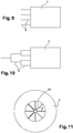
Selon une seconde variante, la chambre est de forme annulaire, les microcanaux étant agencés en étoile et débouchant en périphérie interne de la chambre.According to a second variant, the chamber is of annular shape, the microchannels being arranged in a star and opening at the inner periphery of the chamber.
Selon une forme de réalisation de l'invention, le dispositif comporte un corps réalisé en deux parties, le microcanal et la chambre
comportant chacun une paroi définie par l'une de ces deux parties et une autre paroi définie par l'autre de ces deux parties.According to one embodiment of the invention, the device comprises a body made in two parts, the microchannel and the chamber.
each having a wall defined by one of these two parts and another wall defined by the other of these two parts.
De cette manière, il est possible de faire varier les propriétés des gouttes (taille, vitesse,...) par simple changement de l'une ou de l'autre des deux parties précitées.In this way, it is possible to vary the properties of the drops (size, speed, ...) by simply changing one or the other of the two aforementioned parts.
Ceci permet également de disposer d'un microcanal de hauteur réduite et donc de former des gouttes très petites (inférieures à 10 µ![]()
![]()
![]()
![]()
L'invention sera mieux comprise et d'autres détails, caractéristiques et avantages de l'invention apparaîtront à la lecture de la description suivante faite à titre d'exemple non limitatif en référence aux dessins annexés dans lesquels :
- la
figure 1 est une vue en coupe longitudinale du dispositif selon l'invention ; - la
figure 2 en est une vue en coupe transversale de ce dispositif dans laquelle les gouttes formées ne sont pas représentées ; - la
figure 3 est un diagramme représentant la taille des gouttes produites en fonction du débit du second fluide ; - les
figures 4 à 6 sont des vues schématiques en coupe transversale du dispositif, illustrant trois variantes de réalisation de l'invention ; - la
figure 7 est une vue correspondant à lafigure 2 , d'un dispositif en deux parties ; - la
figure 8 est une vue en coupe longitudinale du dispositif, selon une variante de réalisation de l'invention ; - la
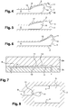
figure 9 est une vue schématique d'une variante de réalisation dans laquelle plusieurs microcanaux agencés en parallèle débouchent dans la chambre ; - la
figure 10 est une vue schématique d'une autre variante de réalisation dans laquelle les microcanaux forment des ramifications débouchant dans la chambre ; - la
figure 1 1 est une vue schématique d'une autre variante de réalisation dans laquelle la chambre est annulaire, les microcanaux étant agencés en étoile.
- the
figure 1 is a longitudinal sectional view of the device according to the invention; - the
figure 2 is a cross-sectional view of this device in which the drops formed are not shown; - the
figure 3 is a diagram representing the size of the drops produced as a function of the flow rate of the second fluid; - the
Figures 4 to 6 are schematic cross-sectional views of the device, illustrating three alternative embodiments of the invention; - the
figure 7 is a view corresponding to thefigure 2 , a device in two parts; - the
figure 8 is a longitudinal sectional view of the device, according to an alternative embodiment of the invention; - the
figure 9 is a schematic view of an alternative embodiment in which a plurality of microchannels arranged in parallel open into the chamber; - the
figure 10 is a schematic view of another embodiment in which the microchannels form branches leading into the chamber; - the
figure 1 1 is a schematic view of another embodiment in which the chamber is annular, the microchannels being arranged in a star.
Les
Le corps 2 comprend de plus un microcanal 8 dont une extrémité est reliée à un orifice de raccordement 9, notamment pour le raccordement d'une seringue ou d'une pipette, et dont l'autre extrémité débouche dans la chambre 3 au niveau de la pointe 6 de la paroi de fond 5.The
La paroi longitudinale inférieure 10 de la chambre est une paroi plane et la paroi longitudinale supérieure 1 1 présente une partie oblique 12 qui s'écarte progressivement de la paroi longitudinale inférieure 10 en direction de l'extrémité opposée 7 de la chambre 3. La divergence des deux parois opposées 10, 1 1 de la chambre 3 correspond par exemple à une pente comprise entre 1 et 4 % environ d'une paroi par rapport à l'autre.The lower
De cette manière, la section de la chambre 3 augmente progressivement de la zone dans laquelle débouche le microcanal 8 vers l'extrémité opposée 7. La hauteur minimum h1 de la chambre 3, c'est-à-dire la hauteur de la chambre 3 au niveau du débouché 13 du microcanal 8, est de l'ordre de 10 à 100 µ![]()
![]()
![]()
![]()
On peut associer à ce dispositif 1 des moyens pour modifier localement la tension de surface du second fluide, comprenant des moyens de chauffage du second fluide, par exemple par des électrodes intégrées au microcircuit ou en utilisant une commande externe de la température. La tension de surface diminue de façon linéaire avec la température de sorte que l'on peut pour une surface fixe changer l'énergie de surface (égale au produit de l'aire totale par la tension de surface) par chauffage par des électrodes, afin de produire les mêmes effets que l'augmentation de section au débouché du microcanal 8, avec un gradient décroissant de température à ce débouché.This
Une variante de réalisation de l'invention est représentée en
Une autre variante est illustrée en
Une dernière variante est visible en
Ces variantes de réalisation permettent de former simultanément plusieurs trains de gouttes à l'intérieur d'une même chambre. Ceci est particulièrement utile lorsque l'on cherche à produire des populations de gouttes, contenant par exemple différents ingrédients. En fonction des besoins, les gouttes ainsi formées peuvent être manipulées ou extraites du dispositif sous la forme de mousse ou d'émulsion.These alternative embodiments make it possible to simultaneously form several sets of drops inside the same chamber. This is particularly useful when seeking to produce droplet populations, for example containing different ingredients. Depending on the requirements, the drops thus formed may be manipulated or extracted from the device in the form of foam or emulsion.
Le fonctionnement de ce dispositif de formation de gouttes va maintenant être détaillé.The operation of this drop forming device will now be detailed.
La chambre 3 est remplie d'un premier fluide, par exemple de l'huile. On raccorde alors une seringue contenant un second fluide, par exemple de l'eau, à l'orifice de raccordement 9 puis on injecte de l'eau dans le microcanal 8 jusqu'à ce que celle-ci atteigne le débouché 13 du microcanal 8.The
Comme indiqué précédemment, l'eau située au niveau du débouché 13 du microcanal 8 est soumise à deux forces antagonistes dues à la tension de surface. Une première force est due à un gradient d'énergie de surface qui tend à extraire l'eau hors du microcanal 8, en formant un doigt 14a qui fait saillie dans la chambre 3 et est rattaché à l'eau contenue dans le microcanal 8.As indicated above, the water located at the
Une seconde force, opposée à la première et correspondant à la force capillaire, tend à maintenir le doigt 14a attaché à l'eau contenue dans le microcanal 8.A second force, opposite to the first and corresponding to the capillary force, tends to keep the
Le doigt 14a se détache lorsque la première force devient supérieure à la seconde force. Cette première force est fonction, pour une géométrie donnée du microcanal 8 et de la chambre 3, du volume du doigt 14a. Ainsi, en fonctionnement, le volume du doigt 14a augmente progressivement, jusqu'à ce que la première force devienne supérieure à la seconde force et que le doigt se détache pour former une goutte 14b.The
Les dimensions du microcanal 8 et l'élargissement de la section de la chambre 3 sont calculés de manière à obtenir une goutte 14 d'une taille déterminée. En particulier, la hauteur h1 de la chambre 3 au débouché du microcanal doit être inférieure au diamètre des gouttes 14 à former.The dimensions of the
Les gouttes d'eau 14b sont ainsi successivement formées dans la chambre, pourvu que de l'eau soit amenée au débouché 13 du microcanal 8.The drops of
En fonction des besoins, un débit d'huile peut être imposé dans la chambre 3.Depending on the needs, an oil flow can be imposed in the
Les gouttes 14b formées au niveau du débouché 13 du microcanal 8 sont transportées naturellement en direction de l'extrémité opposée 7 de la chambre 3, en raison de l'élargissement de leur section de passage dans la chambre. En effet, comme vu ci-dessus, une goutte 14b située dans une zone de faible section, dans laquelle elle prend une forme écrasée, sera naturellement attirée par une zone de plus grande section, dans laquelle elle peut prendre une forme plus sphérique et donc moins contrainte. Comme cela est visible sur la
La
Le fonctionnement du dispositif est notamment indépendant de la nature des fluides (gaz ou liquide) et de la valeur de la tension de surface.The operation of the device is particularly independent of the nature of the fluids (gas or liquid) and the value of the surface tension.
Selon une variante de réalisation représentée à la
La
Ceci permet de former des gouttes ou des bulles dont la vitesse de déplacement sera inférieure à celle des gouttes ou des bulles formées avec le dispositif de la
La
La
De cette manière, il est possible de faire varier les propriétés des gouttes (taille, vitesse, ...) par simple changement de l'une ou de l'autre des parties 2a, 2b.In this way, it is possible to vary the properties of the drops (size, speed, ...) by simply changing one or other of the
Ceci permet également de disposer d'un microcanal de hauteur réduite et donc de former des gouttes très petites (inférieures à 10 µ![]()
![]()
![]()
![]()
Les matériaux utilisés pour les parties 2a et 2b peuvent être différents ou non. De plus, les deux parties 2a, 2b peuvent être collées ensemble, de manière indémontable, pour former un dispositif qui produit des gouttes de même taille. Elles peuvent à l'inverse être fixées l'une à l'autre de manière amovible, afin de pouvoir changer la taille des gouttes par remplacement de l'une ou l'autre des parties.The materials used for
La
Claims (12)
- Method for forming drops (14) of a second fluid in a first fluid using a device (1) for forming drops (14) in a microfluidic circuit, the device comprising a chamber (3) containing the first fluid and delimited by two opposite walls (10, 11) which diverge from one another in at least one given direction and a microchannel (8) which contains the second fluid and which opens into the said chamber (3) upstream of the chamber with respect to the given direction, the mouth (13) where the microchannel (8) opens into the chamber (3) comprising an increase in the passage cross section for the second fluid, the method comprising a step consisting in conveying the second fluid as far as the mouth (13) where the microchannel (8) opens into the chamber (3), the increase in the passage cross section for the second fluid at the mouth (13) where the microchannel (8) opens into the chamber (3) giving rise to the formation of drops (14) of the second fluid and the detachment thereof from the second fluid contained in the microchannel, independently of the flow rate of the first fluid and/or of the second fluid.
- Method according to Claim 1, characterized in that the height (h1) of the chamber (3) at the mouth (13) of the microchannel (8) is less than the diameter of the drops (14) formed.
- Method according to Claim 1 or 2, characterized in that one of the walls (10, 11) of the chamber comprises a step (16), a concave part (17) or a convex part (18) at the mouth (13) of the microchannel (8).
- Method according to one of Claims 1 to 3, characterized in that the flow rate of the first fluid in the chamber is zero.
- Method according to one of Claims 1 to 3, comprising a step of setting the flow rate of the first fluid in the chamber (3) to a predetermined value.
- Method according to one of Claims 1 to 5, characterized in that the divergence of the two opposite walls (10, 11) of the chamber (3) corresponds to a gradient comprised between 1 and 4% of one wall with respect to the other.
- Method according to one of Claims 1 to 6, comprising a step of locally modifying the surface tension of the second fluid using means for locally modifying the surface tension of the second fluid of the device.
- Method according to Claim 7, characterized in that the means for modifying the surface tension of the second fluid comprise means for heating the second fluid, for example a laser beam applied locally or electrodes incorporated into the microfluidic circuit.
- Method according to one of Claims 1 to 8, characterized in that the device comprises several microchannels (8) opening into the chamber.
- Method according to Claim 9, characterized in that the microchannels (8) are parallel to one another and open onto the same side of the chamber (3).
- Method according to Claim 9, characterized in that the chamber (3) is annular in shape, the microchannels (8) being arranged in a star and opening onto the internal periphery of the chamber (3) .
- Method according to one of Claims 1 to 11, characterized in that the device comprises a body (2) made in two parts (2a, 2b), the microchannel (8) and the chamber (3) each one comprising a wall defined by one of the parts (2a) and another wall defined by the other part (2b).
Priority Applications (1)
| Application Number | Priority Date | Filing Date | Title |
|---|---|---|---|
| EP19158130.5A EP3549905B1 (en) | 2010-03-30 | 2011-03-28 | Device for forming drops in a microfluidic circuit |
Applications Claiming Priority (2)
| Application Number | Priority Date | Filing Date | Title |
|---|---|---|---|
| FR1001298A FR2958186A1 (en) | 2010-03-30 | 2010-03-30 | DEVICE FOR FORMING DROPS IN A MICROFLUID CIRCUIT. |
| PCT/FR2011/050677 WO2011121220A1 (en) | 2010-03-30 | 2011-03-28 | Device for forming drops in a microfluidic circuit |
Related Child Applications (2)
| Application Number | Title | Priority Date | Filing Date |
|---|---|---|---|
| EP19158130.5A Division-Into EP3549905B1 (en) | 2010-03-30 | 2011-03-28 | Device for forming drops in a microfluidic circuit |
| EP19158130.5A Division EP3549905B1 (en) | 2010-03-30 | 2011-03-28 | Device for forming drops in a microfluidic circuit |
Publications (2)
| Publication Number | Publication Date |
|---|---|
| EP2552823A1 EP2552823A1 (en) | 2013-02-06 |
| EP2552823B1 true EP2552823B1 (en) | 2019-05-08 |
Family
ID=43086882
Family Applications (2)
| Application Number | Title | Priority Date | Filing Date |
|---|---|---|---|
| EP19158130.5A Active EP3549905B1 (en) | 2010-03-30 | 2011-03-28 | Device for forming drops in a microfluidic circuit |
| EP11719305.2A Active EP2552823B1 (en) | 2010-03-30 | 2011-03-28 | Method for forming drops in a microfluidic circuit |
Family Applications Before (1)
| Application Number | Title | Priority Date | Filing Date |
|---|---|---|---|
| EP19158130.5A Active EP3549905B1 (en) | 2010-03-30 | 2011-03-28 | Device for forming drops in a microfluidic circuit |
Country Status (7)
| Country | Link |
|---|---|
| US (1) | US9133009B2 (en) |
| EP (2) | EP3549905B1 (en) |
| JP (1) | JP6246587B2 (en) |
| CN (1) | CN102892704B (en) |
| ES (2) | ES2737887T3 (en) |
| FR (1) | FR2958186A1 (en) |
| WO (1) | WO2011121220A1 (en) |
Families Citing this family (42)
| Publication number | Priority date | Publication date | Assignee | Title |
|---|---|---|---|---|
| FR2959564B1 (en) * | 2010-04-28 | 2012-06-08 | Commissariat Energie Atomique | DEVICE FORMING A PRESSURE GAUGE FOR THE DIPHASIC FLUID PRESSURE MEASUREMENT, METHOD OF MAKING THE SAME, AND ASSOCIATED FLUID NETWORK |
| US9951386B2 (en) | 2014-06-26 | 2018-04-24 | 10X Genomics, Inc. | Methods and systems for processing polynucleotides |
| US9701998B2 (en) | 2012-12-14 | 2017-07-11 | 10X Genomics, Inc. | Methods and systems for processing polynucleotides |
| US11591637B2 (en) | 2012-08-14 | 2023-02-28 | 10X Genomics, Inc. | Compositions and methods for sample processing |
| US10752949B2 (en) | 2012-08-14 | 2020-08-25 | 10X Genomics, Inc. | Methods and systems for processing polynucleotides |
| US10584381B2 (en) | 2012-08-14 | 2020-03-10 | 10X Genomics, Inc. | Methods and systems for processing polynucleotides |
| US10323279B2 (en) | 2012-08-14 | 2019-06-18 | 10X Genomics, Inc. | Methods and systems for processing polynucleotides |
| FR2996544B1 (en) * | 2012-10-08 | 2015-03-13 | Ecole Polytech | MICROFLUIDIC CIRCUIT FOR COMBINING DROPS OF MULTIPLE FLUIDS AND CORRESPONDING MICROFLUIDIC PROCESS. |
| FR2996545B1 (en) * | 2012-10-08 | 2016-03-25 | Ecole Polytech | MICROFLUIDIC METHOD FOR PROCESSING AND ANALYZING A SOLUTION CONTAINING BIOLOGICAL MATERIAL, AND CORRESPONDING MICROFLUIDIC CIRCUIT |
| US10533221B2 (en) | 2012-12-14 | 2020-01-14 | 10X Genomics, Inc. | Methods and systems for processing polynucleotides |
| BR112015019159A2 (en) | 2013-02-08 | 2017-07-18 | 10X Genomics Inc | polynucleotide barcode generation |
| CN114534806B (en) | 2014-04-10 | 2024-03-29 | 10X基因组学有限公司 | Fluidic devices, systems and methods for packaging and partitioning reagents and uses thereof |
| WO2015200893A2 (en) | 2014-06-26 | 2015-12-30 | 10X Genomics, Inc. | Methods of analyzing nucleic acids from individual cells or cell populations |
| CN107109319B (en) | 2014-10-17 | 2020-11-27 | 巴黎综合理工学院 | Method for processing droplets containing a sample |
| US9975122B2 (en) | 2014-11-05 | 2018-05-22 | 10X Genomics, Inc. | Instrument systems for integrated sample processing |
| KR102528348B1 (en) | 2015-03-16 | 2023-05-03 | 루미넥스 코포레이션 | Device and method for multi-stepped channel emulsification |
| CN107405633A (en) * | 2015-05-22 | 2017-11-28 | 香港科技大学 | Droplet generator based on high-aspect-ratio inductive formation drop |
| WO2017197338A1 (en) | 2016-05-13 | 2017-11-16 | 10X Genomics, Inc. | Microfluidic systems and methods of use |
| WO2018099420A1 (en) * | 2016-11-30 | 2018-06-07 | 领航基因科技(杭州)有限公司 | Droplet digital pcr chip |
| US10815525B2 (en) | 2016-12-22 | 2020-10-27 | 10X Genomics, Inc. | Methods and systems for processing polynucleotides |
| US10011872B1 (en) | 2016-12-22 | 2018-07-03 | 10X Genomics, Inc. | Methods and systems for processing polynucleotides |
| US10550429B2 (en) | 2016-12-22 | 2020-02-04 | 10X Genomics, Inc. | Methods and systems for processing polynucleotides |
| US10258741B2 (en) | 2016-12-28 | 2019-04-16 | Cequr Sa | Microfluidic flow restrictor and system |
| CN110945139B (en) | 2017-05-18 | 2023-09-05 | 10X基因组学有限公司 | Method and system for sorting droplets and beads |
| US10544413B2 (en) | 2017-05-18 | 2020-01-28 | 10X Genomics, Inc. | Methods and systems for sorting droplets and beads |
| US10821442B2 (en) | 2017-08-22 | 2020-11-03 | 10X Genomics, Inc. | Devices, systems, and kits for forming droplets |
| CN107442191A (en) * | 2017-09-20 | 2017-12-08 | 厦门大学 | A kind of centrifugal type microfludic chip for Water-In-Oil drop formation |
| TWI651074B (en) * | 2017-10-25 | 2019-02-21 | 台達電子工業股份有限公司 | Mixing method and mixing apparatus for particle agglutination |
| WO2019083852A1 (en) | 2017-10-26 | 2019-05-02 | 10X Genomics, Inc. | Microfluidic channel networks for partitioning |
| SG11201913654QA (en) | 2017-11-15 | 2020-01-30 | 10X Genomics Inc | Functionalized gel beads |
| US10829815B2 (en) | 2017-11-17 | 2020-11-10 | 10X Genomics, Inc. | Methods and systems for associating physical and genetic properties of biological particles |
| US11465148B2 (en) * | 2018-04-16 | 2022-10-11 | Pattern Bioscience, Inc. | Methods and apparatus for forming 2-dimensional drop arrays |
| US11130120B2 (en) | 2018-10-01 | 2021-09-28 | Lifeng XIAO | Micro-pipette tip for forming micro-droplets |
| US10486155B1 (en) | 2018-10-22 | 2019-11-26 | Klaris Corporation | Vacuum-loaded, droplet-generating microfluidic chips and related methods |
| WO2020109379A1 (en) | 2018-11-27 | 2020-06-04 | Stilla Technologies | Microfluidic chip architecture with optimized phase flow |
| WO2020109388A1 (en) | 2018-11-27 | 2020-06-04 | Stilla Technologies | Wells for optimized sample loading in microfluidic chips |
| CN112739459A (en) * | 2019-02-04 | 2021-04-30 | 伊鲁米纳公司 | Microfluidic droplet generator |
| CN114025880B (en) | 2019-04-26 | 2023-10-10 | 斯蒂拉科技公司 | Polymerase chain reaction apparatus and method for pressure controlled release of fluids |
| US11919002B2 (en) | 2019-08-20 | 2024-03-05 | 10X Genomics, Inc. | Devices and methods for generating and recovering droplets |
| US10953404B1 (en) | 2020-04-24 | 2021-03-23 | Pattern Bioscience, Inc. | Apparatuses for contactless loading and imaging of microfluidic chips and related methods |
| CN114669335B (en) * | 2020-12-24 | 2023-06-16 | 广东奥素液芯微纳科技有限公司 | Micro-droplet generation method and micro-droplet application method |
| CN114471765B (en) * | 2022-01-18 | 2023-04-21 | 北京保利微芯科技有限公司 | Centrifugal liquid drop generating chip |
Family Cites Families (15)
| Publication number | Priority date | Publication date | Assignee | Title |
|---|---|---|---|---|
| WO2003008937A2 (en) * | 2001-07-18 | 2003-01-30 | The Regents Of The University Of Michigan | Gas-focusing flow cytometer cell and flow cytometer detection system with waveguide optics |
| US7759111B2 (en) * | 2004-08-27 | 2010-07-20 | The Regents Of The University Of California | Cell encapsulation microfluidic device |
| DE102005048259B4 (en) * | 2005-10-07 | 2007-09-13 | Landesstiftung Baden-Württemberg | Apparatus and method for producing a mixture of two intractable phases |
| US20080014589A1 (en) * | 2006-05-11 | 2008-01-17 | Link Darren R | Microfluidic devices and methods of use thereof |
| CN101484229A (en) * | 2006-05-26 | 2009-07-15 | 绿色领导科技有限公司 | Method of treating combustion gases |
| WO2008148200A1 (en) * | 2007-06-05 | 2008-12-11 | Eugenia Kumacheva | Multiple continuous microfluidic reactors for the scaled up synthesis of gel or polymer particles |
| GB0712860D0 (en) * | 2007-07-03 | 2007-08-08 | Eastman Kodak Co | continuous inkjet drop generation device |
| GB0712863D0 (en) * | 2007-07-03 | 2007-08-08 | Eastman Kodak Co | Monodisperse droplet generation |
| WO2009048532A2 (en) * | 2007-10-05 | 2009-04-16 | President And Fellows Of Harvard College | Formation of particles for ultrasound application, drug release, and other uses, and microfluidic methods of preparation |
| US20090098168A1 (en) * | 2007-10-08 | 2009-04-16 | The Regents Of The University Of California | Multiple-layer microbubble liposphere drug delivery vehicle and system |
| JP4661942B2 (en) * | 2008-05-13 | 2011-03-30 | ソニー株式会社 | Microchip and its channel structure |
| WO2010033200A2 (en) * | 2008-09-19 | 2010-03-25 | President And Fellows Of Harvard College | Creation of libraries of droplets and related species |
| EP2411134B1 (en) * | 2009-03-25 | 2015-02-18 | Eastman Kodak Company | Droplet generation |
| CN102648053B (en) * | 2009-10-27 | 2016-04-27 | 哈佛学院院长等 | Drop formation technology |
| US20110223314A1 (en) * | 2010-03-10 | 2011-09-15 | Xiaoxiao Zhang | Efficient microencapsulation |
-
2010
- 2010-03-30 FR FR1001298A patent/FR2958186A1/en active Pending
-
2011
- 2011-03-28 US US13/637,779 patent/US9133009B2/en active Active
- 2011-03-28 WO PCT/FR2011/050677 patent/WO2011121220A1/en active Application Filing
- 2011-03-28 JP JP2013501905A patent/JP6246587B2/en active Active
- 2011-03-28 ES ES11719305T patent/ES2737887T3/en active Active
- 2011-03-28 ES ES19158130T patent/ES2904979T3/en active Active
- 2011-03-28 EP EP19158130.5A patent/EP3549905B1/en active Active
- 2011-03-28 CN CN201180017345.2A patent/CN102892704B/en active Active
- 2011-03-28 EP EP11719305.2A patent/EP2552823B1/en active Active
Non-Patent Citations (1)
| Title |
|---|
| None * |
Also Published As
| Publication number | Publication date |
|---|---|
| US20130078164A1 (en) | 2013-03-28 |
| ES2904979T3 (en) | 2022-04-06 |
| US9133009B2 (en) | 2015-09-15 |
| EP3549905A1 (en) | 2019-10-09 |
| CN102892704A (en) | 2013-01-23 |
| EP3549905B1 (en) | 2021-11-03 |
| ES2737887T3 (en) | 2020-01-16 |
| WO2011121220A1 (en) | 2011-10-06 |
| JP6246587B2 (en) | 2017-12-13 |
| CN102892704B (en) | 2016-03-02 |
| JP2013523431A (en) | 2013-06-17 |
| FR2958186A1 (en) | 2011-10-07 |
| EP2552823A1 (en) | 2013-02-06 |
Similar Documents
| Publication | Publication Date | Title |
|---|---|---|
| EP2552823B1 (en) | Method for forming drops in a microfluidic circuit | |
| EP2127748B1 (en) | Method for sorting particles or clusters of particles in a fluid circulating in a channel | |
| Ofner et al. | High‐throughput step emulsification for the production of functional materials using a glass microfluidic device | |
| EP2574401B1 (en) | Method for Merging Drops in a Microfluid Circuit | |
| EP3318328B1 (en) | Sorting device for particles present in a fluid sample | |
| Utada et al. | Monodisperse double emulsions generated from a microcapillary device | |
| EP2119504B1 (en) | Device and method for separating a suspension | |
| JP5335784B2 (en) | Generation of monodisperse droplets | |
| Zhang et al. | Hydrodynamic dispensing and electrical manipulation of attolitre droplets | |
| EP1975486B1 (en) | Dispensing valve | |
| WO2007031615A1 (en) | Microfluidic flow device having at least one connecting channel linking two channels and corresponding method for using same | |
| EP2490823B1 (en) | Dispensing head for a fluid dispenser | |
| FR2930457A1 (en) | PROCESS FOR MANUFACTURING RECONFIGURABLE MICROCHANNELS | |
| Cubaud et al. | Formation of miscible fluid microstructures by hydrodynamic focusing in plane geometries | |
| EP3162441A1 (en) | Microfluidic device coupling two flow zones | |
| FR2907030A1 (en) | Managing plugs in fluid stream, e.g. in millifluid analysis system, includes forming plugs in carrier phase in situ from two immiscible fluids flowing in upstream tubes | |
| EP4263037A1 (en) | Module for use in a system for sorting centrifugally expelled particles according to size, sorting system and method for configuring such a system | |
| FR2971953A1 (en) | MICROFLUIDIC EXTRACTION DEVICE WITH STABILIZED LIQUID-LIQUID INTERFACE | |
| Huang et al. | Gas-assisted microfluidic step-emulsification for generating micron-and submicron-sized droplets | |
| Liu et al. | Injection angle dependence in flow focusing based droplet formation | |
| Lin et al. | 3-dimensional microorifice fabricated utilizing single undercut etching process for producing ultrasmall water and chitosan droplets | |
| EP2996786A2 (en) | Device for forced drainage of a multiphase fluid | |
| WO2015097300A1 (en) | Microfluidic device for handling immiscible fluids | |
| Chang et al. | Controlled W/O/W double emulsification in 3-D PDMS micro-channels | |
| Li et al. | Two same-sized droplets coalescence by laser-induced cavitation bubbles |
Legal Events
| Date | Code | Title | Description |
|---|---|---|---|
| PUAI | Public reference made under article 153(3) epc to a published international application that has entered the european phase |
Free format text: ORIGINAL CODE: 0009012 |
|
| 17P | Request for examination filed |
Effective date: 20120913 |
|
| AK | Designated contracting states |
Kind code of ref document: A1 Designated state(s): AL AT BE BG CH CY CZ DE DK EE ES FI FR GB GR HR HU IE IS IT LI LT LU LV MC MK MT NL NO PL PT RO RS SE SI SK SM TR |
|
| DAX | Request for extension of the european patent (deleted) | ||
| RAP1 | Party data changed (applicant data changed or rights of an application transferred) |
Owner name: ECOLE POLYTECHNIQUE Owner name: CENTRE NATIONAL DE LA RECHERCHE SCIENTIFIQUE -CNRS |
|
| STAA | Information on the status of an ep patent application or granted ep patent |
Free format text: STATUS: EXAMINATION IS IN PROGRESS |
|
| 17Q | First examination report despatched |
Effective date: 20170217 |
|
| GRAP | Despatch of communication of intention to grant a patent |
Free format text: ORIGINAL CODE: EPIDOSNIGR1 |
|
| STAA | Information on the status of an ep patent application or granted ep patent |
Free format text: STATUS: GRANT OF PATENT IS INTENDED |
|
| INTG | Intention to grant announced |
Effective date: 20181019 |
|
| GRAS | Grant fee paid |
Free format text: ORIGINAL CODE: EPIDOSNIGR3 |
|
| GRAA | (expected) grant |
Free format text: ORIGINAL CODE: 0009210 |
|
| STAA | Information on the status of an ep patent application or granted ep patent |
Free format text: STATUS: THE PATENT HAS BEEN GRANTED |
|
| AK | Designated contracting states |
Kind code of ref document: B1 Designated state(s): AL AT BE BG CH CY CZ DE DK EE ES FI FR GB GR HR HU IE IS IT LI LT LU LV MC MK MT NL NO PL PT RO RS SE SI SK SM TR |
|
| REG | Reference to a national code |
Ref country code: GB Ref legal event code: FG4D Free format text: NOT ENGLISH |
|
| REG | Reference to a national code |
Ref country code: CH Ref legal event code: EP Ref country code: AT Ref legal event code: REF Ref document number: 1129839 Country of ref document: AT Kind code of ref document: T Effective date: 20190515 |
|
| REG | Reference to a national code |
Ref country code: DE Ref legal event code: R096 Ref document number: 602011058730 Country of ref document: DE Ref country code: IE Ref legal event code: FG4D Free format text: LANGUAGE OF EP DOCUMENT: FRENCH |
|
| REG | Reference to a national code |
Ref country code: NL Ref legal event code: FP |
|
| REG | Reference to a national code |
Ref country code: LT Ref legal event code: MG4D |
|
| PG25 | Lapsed in a contracting state [announced via postgrant information from national office to epo] |
Ref country code: LT Free format text: LAPSE BECAUSE OF FAILURE TO SUBMIT A TRANSLATION OF THE DESCRIPTION OR TO PAY THE FEE WITHIN THE PRESCRIBED TIME-LIMIT Effective date: 20190508 Ref country code: HR Free format text: LAPSE BECAUSE OF FAILURE TO SUBMIT A TRANSLATION OF THE DESCRIPTION OR TO PAY THE FEE WITHIN THE PRESCRIBED TIME-LIMIT Effective date: 20190508 Ref country code: FI Free format text: LAPSE BECAUSE OF FAILURE TO SUBMIT A TRANSLATION OF THE DESCRIPTION OR TO PAY THE FEE WITHIN THE PRESCRIBED TIME-LIMIT Effective date: 20190508 Ref country code: AL Free format text: LAPSE BECAUSE OF FAILURE TO SUBMIT A TRANSLATION OF THE DESCRIPTION OR TO PAY THE FEE WITHIN THE PRESCRIBED TIME-LIMIT Effective date: 20190508 Ref country code: NO Free format text: LAPSE BECAUSE OF FAILURE TO SUBMIT A TRANSLATION OF THE DESCRIPTION OR TO PAY THE FEE WITHIN THE PRESCRIBED TIME-LIMIT Effective date: 20190808 Ref country code: SE Free format text: LAPSE BECAUSE OF FAILURE TO SUBMIT A TRANSLATION OF THE DESCRIPTION OR TO PAY THE FEE WITHIN THE PRESCRIBED TIME-LIMIT Effective date: 20190508 Ref country code: PT Free format text: LAPSE BECAUSE OF FAILURE TO SUBMIT A TRANSLATION OF THE DESCRIPTION OR TO PAY THE FEE WITHIN THE PRESCRIBED TIME-LIMIT Effective date: 20190908 |
|
| PG25 | Lapsed in a contracting state [announced via postgrant information from national office to epo] |
Ref country code: BG Free format text: LAPSE BECAUSE OF FAILURE TO SUBMIT A TRANSLATION OF THE DESCRIPTION OR TO PAY THE FEE WITHIN THE PRESCRIBED TIME-LIMIT Effective date: 20190808 Ref country code: GR Free format text: LAPSE BECAUSE OF FAILURE TO SUBMIT A TRANSLATION OF THE DESCRIPTION OR TO PAY THE FEE WITHIN THE PRESCRIBED TIME-LIMIT Effective date: 20190809 Ref country code: LV Free format text: LAPSE BECAUSE OF FAILURE TO SUBMIT A TRANSLATION OF THE DESCRIPTION OR TO PAY THE FEE WITHIN THE PRESCRIBED TIME-LIMIT Effective date: 20190508 Ref country code: RS Free format text: LAPSE BECAUSE OF FAILURE TO SUBMIT A TRANSLATION OF THE DESCRIPTION OR TO PAY THE FEE WITHIN THE PRESCRIBED TIME-LIMIT Effective date: 20190508 |
|
| REG | Reference to a national code |
Ref country code: ES Ref legal event code: FG2A Ref document number: 2737887 Country of ref document: ES Kind code of ref document: T3 Effective date: 20200116 |
|
| PG25 | Lapsed in a contracting state [announced via postgrant information from national office to epo] |
Ref country code: EE Free format text: LAPSE BECAUSE OF FAILURE TO SUBMIT A TRANSLATION OF THE DESCRIPTION OR TO PAY THE FEE WITHIN THE PRESCRIBED TIME-LIMIT Effective date: 20190508 Ref country code: SK Free format text: LAPSE BECAUSE OF FAILURE TO SUBMIT A TRANSLATION OF THE DESCRIPTION OR TO PAY THE FEE WITHIN THE PRESCRIBED TIME-LIMIT Effective date: 20190508 Ref country code: RO Free format text: LAPSE BECAUSE OF FAILURE TO SUBMIT A TRANSLATION OF THE DESCRIPTION OR TO PAY THE FEE WITHIN THE PRESCRIBED TIME-LIMIT Effective date: 20190508 Ref country code: CZ Free format text: LAPSE BECAUSE OF FAILURE TO SUBMIT A TRANSLATION OF THE DESCRIPTION OR TO PAY THE FEE WITHIN THE PRESCRIBED TIME-LIMIT Effective date: 20190508 Ref country code: DK Free format text: LAPSE BECAUSE OF FAILURE TO SUBMIT A TRANSLATION OF THE DESCRIPTION OR TO PAY THE FEE WITHIN THE PRESCRIBED TIME-LIMIT Effective date: 20190508 |
|
| REG | Reference to a national code |
Ref country code: DE Ref legal event code: R097 Ref document number: 602011058730 Country of ref document: DE |
|
| PG25 | Lapsed in a contracting state [announced via postgrant information from national office to epo] |
Ref country code: SM Free format text: LAPSE BECAUSE OF FAILURE TO SUBMIT A TRANSLATION OF THE DESCRIPTION OR TO PAY THE FEE WITHIN THE PRESCRIBED TIME-LIMIT Effective date: 20190508 |
|
| PLBE | No opposition filed within time limit |
Free format text: ORIGINAL CODE: 0009261 |
|
| STAA | Information on the status of an ep patent application or granted ep patent |
Free format text: STATUS: NO OPPOSITION FILED WITHIN TIME LIMIT |
|
| PG25 | Lapsed in a contracting state [announced via postgrant information from national office to epo] |
Ref country code: TR Free format text: LAPSE BECAUSE OF FAILURE TO SUBMIT A TRANSLATION OF THE DESCRIPTION OR TO PAY THE FEE WITHIN THE PRESCRIBED TIME-LIMIT Effective date: 20190508 |
|
| 26N | No opposition filed |
Effective date: 20200211 |
|
| PG25 | Lapsed in a contracting state [announced via postgrant information from national office to epo] |
Ref country code: PL Free format text: LAPSE BECAUSE OF FAILURE TO SUBMIT A TRANSLATION OF THE DESCRIPTION OR TO PAY THE FEE WITHIN THE PRESCRIBED TIME-LIMIT Effective date: 20190508 |
|
| PG25 | Lapsed in a contracting state [announced via postgrant information from national office to epo] |
Ref country code: SI Free format text: LAPSE BECAUSE OF FAILURE TO SUBMIT A TRANSLATION OF THE DESCRIPTION OR TO PAY THE FEE WITHIN THE PRESCRIBED TIME-LIMIT Effective date: 20190508 |
|
| REG | Reference to a national code |
Ref country code: AT Ref legal event code: UEP Ref document number: 1129839 Country of ref document: AT Kind code of ref document: T Effective date: 20190508 |
|
| PG25 | Lapsed in a contracting state [announced via postgrant information from national office to epo] |
Ref country code: MC Free format text: LAPSE BECAUSE OF FAILURE TO SUBMIT A TRANSLATION OF THE DESCRIPTION OR TO PAY THE FEE WITHIN THE PRESCRIBED TIME-LIMIT Effective date: 20190508 |
|
| PG25 | Lapsed in a contracting state [announced via postgrant information from national office to epo] |
Ref country code: LU Free format text: LAPSE BECAUSE OF NON-PAYMENT OF DUE FEES Effective date: 20200328 |
|
| PG25 | Lapsed in a contracting state [announced via postgrant information from national office to epo] |
Ref country code: IE Free format text: LAPSE BECAUSE OF NON-PAYMENT OF DUE FEES Effective date: 20200328 |
|
| PG25 | Lapsed in a contracting state [announced via postgrant information from national office to epo] |
Ref country code: MT Free format text: LAPSE BECAUSE OF FAILURE TO SUBMIT A TRANSLATION OF THE DESCRIPTION OR TO PAY THE FEE WITHIN THE PRESCRIBED TIME-LIMIT Effective date: 20190508 Ref country code: CY Free format text: LAPSE BECAUSE OF FAILURE TO SUBMIT A TRANSLATION OF THE DESCRIPTION OR TO PAY THE FEE WITHIN THE PRESCRIBED TIME-LIMIT Effective date: 20190508 |
|
| PG25 | Lapsed in a contracting state [announced via postgrant information from national office to epo] |
Ref country code: MK Free format text: LAPSE BECAUSE OF FAILURE TO SUBMIT A TRANSLATION OF THE DESCRIPTION OR TO PAY THE FEE WITHIN THE PRESCRIBED TIME-LIMIT Effective date: 20190508 Ref country code: IS Free format text: LAPSE BECAUSE OF FAILURE TO SUBMIT A TRANSLATION OF THE DESCRIPTION OR TO PAY THE FEE WITHIN THE PRESCRIBED TIME-LIMIT Effective date: 20190908 |
|
| PGFP | Annual fee paid to national office [announced via postgrant information from national office to epo] |
Ref country code: NL Payment date: 20230221 Year of fee payment: 13 |
|
| PGFP | Annual fee paid to national office [announced via postgrant information from national office to epo] |
Ref country code: FR Payment date: 20230222 Year of fee payment: 13 Ref country code: AT Payment date: 20230222 Year of fee payment: 13 |
|
| PGFP | Annual fee paid to national office [announced via postgrant information from national office to epo] |
Ref country code: IT Payment date: 20230221 Year of fee payment: 13 Ref country code: GB Payment date: 20230222 Year of fee payment: 13 Ref country code: DE Payment date: 20230221 Year of fee payment: 13 Ref country code: BE Payment date: 20230221 Year of fee payment: 13 |
|
| P01 | Opt-out of the competence of the unified patent court (upc) registered |
Effective date: 20230601 |
|
| PGFP | Annual fee paid to national office [announced via postgrant information from national office to epo] |
Ref country code: ES Payment date: 20230403 Year of fee payment: 13 Ref country code: CH Payment date: 20230401 Year of fee payment: 13 |