EP2552652B1 - Rock drilling machine and use thereof for hindering occurrence and spreading of cavitation bubbles - Google Patents
Rock drilling machine and use thereof for hindering occurrence and spreading of cavitation bubbles Download PDFInfo
- Publication number
- EP2552652B1 EP2552652B1 EP11763141.6A EP11763141A EP2552652B1 EP 2552652 B1 EP2552652 B1 EP 2552652B1 EP 11763141 A EP11763141 A EP 11763141A EP 2552652 B1 EP2552652 B1 EP 2552652B1
- Authority
- EP
- European Patent Office
- Prior art keywords
- drilling machine
- rock drilling
- oil
- cavitation
- restrictions
- Prior art date
- Legal status (The legal status is an assumption and is not a legal conclusion. Google has not performed a legal analysis and makes no representation as to the accuracy of the status listed.)
- Active
Links
Images
Classifications
-
- E—FIXED CONSTRUCTIONS
- E21—EARTH OR ROCK DRILLING; MINING
- E21B—EARTH OR ROCK DRILLING; OBTAINING OIL, GAS, WATER, SOLUBLE OR MELTABLE MATERIALS OR A SLURRY OF MINERALS FROM WELLS
- E21B1/00—Percussion drilling
- E21B1/36—Tool-carrier piston type, i.e. in which the tool is connected to an impulse member
-
- B—PERFORMING OPERATIONS; TRANSPORTING
- B25—HAND TOOLS; PORTABLE POWER-DRIVEN TOOLS; MANIPULATORS
- B25D—PERCUSSIVE TOOLS
- B25D9/00—Portable percussive tools with fluid-pressure drive, i.e. driven directly by fluids, e.g. having several percussive tool bits operated simultaneously
- B25D9/06—Means for driving the impulse member
- B25D9/12—Means for driving the impulse member comprising a built-in liquid motor, i.e. the tool being driven by hydraulic pressure
-
- B—PERFORMING OPERATIONS; TRANSPORTING
- B25—HAND TOOLS; PORTABLE POWER-DRIVEN TOOLS; MANIPULATORS
- B25D—PERCUSSIVE TOOLS
- B25D17/00—Details of, or accessories for, portable power-driven percussive tools
- B25D17/06—Hammer pistons; Anvils ; Guide-sleeves for pistons
-
- B—PERFORMING OPERATIONS; TRANSPORTING
- B25—HAND TOOLS; PORTABLE POWER-DRIVEN TOOLS; MANIPULATORS
- B25D—PERCUSSIVE TOOLS
- B25D17/00—Details of, or accessories for, portable power-driven percussive tools
- B25D17/24—Damping the reaction force
- B25D17/245—Damping the reaction force using a fluid
-
- B—PERFORMING OPERATIONS; TRANSPORTING
- B25—HAND TOOLS; PORTABLE POWER-DRIVEN TOOLS; MANIPULATORS
- B25D—PERCUSSIVE TOOLS
- B25D2217/00—Details of, or accessories for, portable power-driven percussive tools
- B25D2217/0011—Details of anvils, guide-sleeves or pistons
- B25D2217/0019—Guide-sleeves
Definitions
- the present invention concerns a rock drilling machine and a method to hinder the occurrence and spreading of cavitation bubbles in a rock drilling machine.
- Cavitation is the occurrence of cavities (voids) in liquids in the form of bubbles where the liquid has transformed into a gas when the static pressure in the liquid has decreased. Cavitation is a mixture of gas formation, the release of trapped air in the liquid and the expansion of air bubbles contained in the liquid.
- Cavitation occurs for example in the area around the damper piston, i.e. the component that forces the adapter/drilling steel/bore crown against the rock so that joints can be tightened between impacts, when the damper piston moves forwards and thereby quickly increases the volume between the damper piston and the damper chamber or the machine body.
- This problem is usually combatted using a one way valve that fills the volume with oil in order to decrease the occurrence of cavitation bubbles (see US 4,993,504 ).
- a substantial pressure decrease occurs which leads to cavitation if the oil cannot be replaced at the same rate as the volume increases. Cavitation bubbles therefore occur since the hydraulic pressure is low and the pressure decrease propagates through all hydraulically connected spaces.
- WO 2008/095073 discloses, in a valve-less percussive drill of the hydraulic tyre and incorporating a hammer assembly, that an "intermediate" shoulder between the head portion and cushion portion of a reciprocating piston engages the end face of a distributor or liner, rather than an interior bearing structure for the piston.
- This end face can be made harder than the ulterior bearing structure, which may include a surface made of a different material than the piston.
- EP 0,648,915 describes a rock drilling device for drilling with a drill string comprising a set of tubes and a set of rods arranged centrally in the set of tubes.
- the rock drilling device comprises means for sensing a liquid pressure in a recoil damper and actuating means for stopping the supply of pressure liquid to a hammer device of the rock drilling device when the pressure in the recoil damper falls below a predetermined value in order to prevent that the drilling tool and/or the machine housing is damaged at a too low damper pressure.
- An aim of the present invention is to provide a rock drilling machine that hinders the spreading of already created cavitation bubbles, and filters the pressure decrease so that new cavitation bubbles do not occur in other volumes.
- a rock drilling machine that comprises a piston that is arranged to move back and forth in a pressure chamber when the rock drilling machine is in use, a cavitation-sensitive component and an oil channel that is arranged to extend between the pressure chamber and said cavitation-sensitive component.
- the oil channel comprises a series of restrictions and oil volumes, i.e. spaces where oil can collect, in order to hinder the movement of cavitation bubbles through said oil channel.
- said series of restrictions and oil volumes at least includes two restrictions and one oil volume, or at least three restrictions and two oil volumes, etc.
- said series of restrictions and oil volumes includes one restriction and two oil volumes, two restrictions and three oil volumes etc.
- Said series of restrictions can however include as many restrictions and oil volumes as desired so that the oil channel between the pressure chamber and the cavitation-sensitive component is as long as possible.
- said series of restrictions and oil volumes comprises alternating restrictions and oil volumes so that the pressure decrease that is formed in the pressure chamber is filtered and does not propagate fully to the cavitation-sensitive component, and the flow of oil in the opposite direction is suppressed.
- the combination of the alternating restrictions and oil volumes in series provides a filter function and a smoother pressure profile adjacent to cavitation-sensitive components in the rock drilling machine.
- restrictions are arranged to decrease the cross sectional area of said oil channel by at least 50%, at least 60%, at least 70%, at least 80% or at least 90% or more.
- restriction in this document is intended to include even a gap between adjacent components of the rock drilling machine through which gap oil can for example be sucked into the pressure chamber when a low pressure occurs in the pressure chamber.
- At least one restriction is arranged exactly adjacent to the pressure chamber, i.e. where the oil channel meets the pressure chamber.
- said cavitation-sensitive component of the rock drilling machine is a seal or a guide, such as a bronze guide.
- said piston is a damper piston, or a piston in the percussion- or breaker part of the rock drilling machine.
- the rock drilling machine comprises a plurality of cavitation-sensitive components and/or a plurality of oil channels that are arranged to extend between one or more pressure chambers to one or more cavitation-sensitive components.
- at least one, a plurality, or all of the pressure chambers of the rock drilling machine are substantially isolated from the spaces hydraulically connected to the pressure chamber. Cavitation-sensitive components are consequently isolated from cavitation and are thereby protected from cavitation damage.
- the total length of said oil channel (measured from the pressure chamber to the cavitation-sensitive component along the oil channel from one end of the oil channel to the other end of the oil channel) is longer than the shortest distance between the pressure chamber and the cavitation-sensitive component (measured from one end of the oil channel to the other end of the oil channel), at least 50% longer, at least 60% longer, at least 70% longer or even longer.
- the present invention also concerns a method to hinder the occurrence and spreading of cavitation bubbles of a rock drilling machine.
- the method comprises the step of arranging an oil channel that is arranged to extend between a piston pressure chamber and a cavitation-sensitive component of the rock drilling machine to comprise a series of restrictions and oil volumes to hinder the movement of cavitation bubbles through said oil channel.
- said series of restrictions and oil volumes includes at least two restrictions and one oil volume or at least three restrictions and two oil volumes.
- said series of restrictions and oil volumes comprises alternating restrictions and oil volumes, or consists of alternating restrictions and oil volumes.
- said restrictions are arranged to decrease said oil channel's cross sectional area by at least 50%, at least 60%, at least 70%, at least 80% or at least 90% or more.
- At least one restriction is arranged exactly adjacent to the pressure chamber.
- said cavitation-sensitive component of the rock drilling machine is a seal or a bronze guide.
- said piston is a damper piston or a piston in the percussion or breaker part of the rock drilling machine.
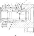
- FIG 1 shows part of a rock drilling machine 10 according to an embodiment of the present invention.
- the rock drilling machine 10 comprises a damper piston 16 that is arranged to move back and forth in a pressure chamber, which in figure 1 , due to the damper piston's position in the pressure chamber, is divided into a front part 12a, and a rear part 12b.
- a seal 14 is arranged at a distance from the pressure chamber 12a, 12b around the damper piston 16.
- the rock drilling machine comprises a first oil channel that comprises a first restriction 18i, a dedicated constriction or obstruction, in order to hinder the passage of cavitation bubbles between the front part of the pressure chamber 12a and the oil volume 20i.
- FIG 1 there is a plurality of interconnected oil channels through which oil can flow from oil volumes 20 in the rock drilling machine between the seal 14 and the pressure chamber 12a, 12b.
- These oil channels comprise a series of alternating restrictions 18 and oil volumes 20 which hinder the spreading of cavitation bubbles between the seal 14 and the pressure chamber 12a, 12b when a low pressure occurs in the pressure chamber.
- the spreading and the occurrence of cavitation bubbles is therefore limited to the pressure chamber 12a, 12b itself, whose material is resistant to cavitation damage.
- the pressure chamber 12a, 12b is substantially isolated from all of the spaces 20 hydraulically connected to the pressure chamber. Cavitation-sensitive components, such as the seal 14, are consequently isolated from cavitation and are thereby protected from cavitation damage.
- the oil channel that includes a series of restrictions 18, 18i and oil volumes 20, 20i has a long extension, i.e. that its total length (measured from the pressure chamber 12 to the seal 14 along the oil channel) is longer than the shortest distance between the pressure chamber 12 and the seal 14 (measured from one end of the oil channel to the other end of the oil channel), at least 50% longer, at least 60% longer, at least 70% longer or even longer.
- a long extension can be achieved for example by the placement of oil volumes 20, 20i and restrictions 18, 18i.
- a long oil channel gives a long signal time for the pressure decrease and the cavitation bubbles/pressure decrease is/are forced to pass through a larger amount (volume) of oil between the pressure chamber 12 and the seal 14.
- a restriction 18 i.e. a dedicated' constriction or obstruction, is arranged to decrease an oil channel's cross sectional area by at least 50%, at least 60%, at least 70%, at least 80% or at least 90% or more. It should be noted that the expression “restriction” is intended to also include a gap 18m between adjacent components of the rock drilling machine.
- the illustrated embodiment shows a damper piston 16.
- the present invention can however be used on another piston of the rock drilling machine, for example a piston in the percussion or breaker part of the rock drilling machine such as a percussion piston or a breaker piston.
- the present invention also concerns a method to hinder the occurrence and spreading of cavitation bubbles of a rock drilling machine.
- the method comprises the step of arranging an oil channel that is arranged to extend between a piston pressure chamber and a cavitation-sensitive component of the rock drilling machine to comprise a series of restrictions that decrease an oil channel's cross sectional area by at least 50%, at least 60%, at least 70%, at least 80% or at least 90% or more, and oil volumes to hinder the movement of cavitation bubbles through said oil channel.
- said oil channel is arranged to comprise a series of alternating restrictions and oil volumes.
Landscapes
- Engineering & Computer Science (AREA)
- Mechanical Engineering (AREA)
- Life Sciences & Earth Sciences (AREA)
- Geology (AREA)
- Mining & Mineral Resources (AREA)
- Physics & Mathematics (AREA)
- Fluid Mechanics (AREA)
- Environmental & Geological Engineering (AREA)
- General Life Sciences & Earth Sciences (AREA)
- Geochemistry & Mineralogy (AREA)
- Percussive Tools And Related Accessories (AREA)
- Earth Drilling (AREA)
Description
- The present invention concerns a rock drilling machine and a method to hinder the occurrence and spreading of cavitation bubbles in a rock drilling machine.
- Cavitation is the occurrence of cavities (voids) in liquids in the form of bubbles where the liquid has transformed into a gas when the static pressure in the liquid has decreased. Cavitation is a mixture of gas formation, the release of trapped air in the liquid and the expansion of air bubbles contained in the liquid.
- In cases where the cavitation bubbles implode when the static pressure increases, a very thin jet stream with large force can be formed from the bubble which can damage solid surfaces in the vicinity. A blister forms in a low pressure zone and adheres to a solid surface and implodes when the surrounding static pressure increases. The effect is the same as thousands of sharp nails hammering the surface with a large force whereby the material's ultimate tensile strength can be exceeded, which eventually gives rise to a visible loss of material, often leaving thousands of small craters in the material. This is a known phenomenon in hydraulic rock drilling machines.
- Cavitation occurs for example in the area around the damper piston, i.e. the component that forces the adapter/drilling steel/bore crown against the rock so that joints can be tightened between impacts, when the damper piston moves forwards and thereby quickly increases the volume between the damper piston and the damper chamber or the machine body. This problem is usually combatted using a one way valve that fills the volume with oil in order to decrease the occurrence of cavitation bubbles (see
US 4,993,504 ). When the damper piston moves forwards, a substantial pressure decrease occurs which leads to cavitation if the oil cannot be replaced at the same rate as the volume increases. Cavitation bubbles therefore occur since the hydraulic pressure is low and the pressure decrease propagates through all hydraulically connected spaces. Oil starts to flow to the area with the lowest pressure from all possible directions. Cavitation bubbles can thereby spread to and/or also occur in places other than in the original space between the damper piston and the damper chamber (machine body). The low pressure causes the oil from surrounding spaces to flow to the low pressure area to re-establish mean pressure in the damper device. For this reason many drilling machines often have a damper accumulator so that a large volume of oil is readily available to even out the hydraulic pressure, but this is not sufficient to solve the cavitation problem. When the cavitation bubbles finally collapse there is an obvious risk that some of them will be located in the vicinity of sensitive components and will for example damage seals. -
WO 2008/095073 discloses, in a valve-less percussive drill of the hydraulic tyre and incorporating a hammer assembly, that an "intermediate" shoulder between the head portion and cushion portion of a reciprocating piston engages the end face of a distributor or liner, rather than an interior bearing structure for the piston. This end face can be made harder than the ulterior bearing structure, which may include a surface made of a different material than the piston. Collectively, the result is a percussive drill with the hammer assembly incorporating the piston substantially less susceptible to failure due to galling as the result of contamination in the working fluid. -
EP 0,648,915 describes a rock drilling device for drilling with a drill string comprising a set of tubes and a set of rods arranged centrally in the set of tubes. The rock drilling device comprises means for sensing a liquid pressure in a recoil damper and actuating means for stopping the supply of pressure liquid to a hammer device of the rock drilling device when the pressure in the recoil damper falls below a predetermined value in order to prevent that the drilling tool and/or the machine housing is damaged at a too low damper pressure. - An aim of the present invention is to provide a rock drilling machine that hinders the spreading of already created cavitation bubbles, and filters the pressure decrease so that new cavitation bubbles do not occur in other volumes.
- This aim is achieved by a rock drilling machine that comprises a piston that is arranged to move back and forth in a pressure chamber when the rock drilling machine is in use, a cavitation-sensitive component and an oil channel that is arranged to extend between the pressure chamber and said cavitation-sensitive component. The oil channel comprises a series of restrictions and oil volumes, i.e. spaces where oil can collect, in order to hinder the movement of cavitation bubbles through said oil channel.
- The movement of oil from the spaces hydraulically connected to the pressure chamber is hindered when a pressure decrease occurs in the pressure chamber. The spread and the occurrence of cavitation bubbles is therefore limited to the pressure chamber itself, whose material is resistant to cavitation damage. Such a solution requires no components with moveable parts and it does not for example require the use of a relatively expensive one way valve, which additionally takes up valuable space in the rock drilling machine.
- According to an embodiment of the invention said series of restrictions and oil volumes at least includes two restrictions and one oil volume, or at least three restrictions and two oil volumes, etc. Alternatively, said series of restrictions and oil volumes includes one restriction and two oil volumes, two restrictions and three oil volumes etc.
- Said series of restrictions can however include as many restrictions and oil volumes as desired so that the oil channel between the pressure chamber and the cavitation-sensitive component is as long as possible. According to an embodiment of the invention said series of restrictions and oil volumes comprises alternating restrictions and oil volumes so that the pressure decrease that is formed in the pressure chamber is filtered and does not propagate fully to the cavitation-sensitive component, and the flow of oil in the opposite direction is suppressed. The combination of the alternating restrictions and oil volumes in series provides a filter function and a smoother pressure profile adjacent to cavitation-sensitive components in the rock drilling machine.
- According to another embodiment of the invention said restrictions are arranged to decrease the cross sectional area of said oil channel by at least 50%, at least 60%, at least 70%, at least 80% or at least 90% or more. It should be noted that the expression "restriction" in this document is intended to include even a gap between adjacent components of the rock drilling machine through which gap oil can for example be sucked into the pressure chamber when a low pressure occurs in the pressure chamber.
- According to a further embodiment of the invention at least one restriction is arranged exactly adjacent to the pressure chamber, i.e. where the oil channel meets the pressure chamber.
- According to an embodiment of the invention said cavitation-sensitive component of the rock drilling machine is a seal or a guide, such as a bronze guide.
- According to another embodiment of the invention said piston is a damper piston, or a piston in the percussion- or breaker part of the rock drilling machine.
- According to a further embodiment of the invention the rock drilling machine comprises a plurality of cavitation-sensitive components and/or a plurality of oil channels that are arranged to extend between one or more pressure chambers to one or more cavitation-sensitive components. According to an embodiment of the invention at least one, a plurality, or all of the pressure chambers of the rock drilling machine are substantially isolated from the spaces hydraulically connected to the pressure chamber. Cavitation-sensitive components are consequently isolated from cavitation and are thereby protected from cavitation damage.
- According to an embodiment of the invention the total length of said oil channel (measured from the pressure chamber to the cavitation-sensitive component along the oil channel from one end of the oil channel to the other end of the oil channel) is longer than the shortest distance between the pressure chamber and the cavitation-sensitive component (measured from one end of the oil channel to the other end of the oil channel), at least 50% longer, at least 60% longer, at least 70% longer or even longer.
- The present invention also concerns a method to hinder the occurrence and spreading of cavitation bubbles of a rock drilling machine. The method comprises the step of arranging an oil channel that is arranged to extend between a piston pressure chamber and a cavitation-sensitive component of the rock drilling machine to comprise a series of restrictions and oil volumes to hinder the movement of cavitation bubbles through said oil channel.
- According to an embodiment of the invention said series of restrictions and oil volumes includes at least two restrictions and one oil volume or at least three restrictions and two oil volumes.
- According to another embodiment of the invention said series of restrictions and oil volumes comprises alternating restrictions and oil volumes, or consists of alternating restrictions and oil volumes.
- According to further embodiment of the invention said restrictions are arranged to decrease said oil channel's cross sectional area by at least 50%, at least 60%, at least 70%, at least 80% or at least 90% or more.
- According to an embodiment of the invention at least one restriction is arranged exactly adjacent to the pressure chamber.
- According to another embodiment of the invention said cavitation-sensitive component of the rock drilling machine is a seal or a bronze guide.
- According to a further embodiment of the invention said piston is a damper piston or a piston in the percussion or breaker part of the rock drilling machine.
- In the following, the present invention will be described in more detail with reference to the accompanying schematic drawing, in which:
-
Figure 1 shows part of a rock drilling machine according to an embodiment of the present invention. - It should be noted that the drawing has not necessarily been drawn to scale and that the dimensions of certain elements may have been exaggerated for the sake of clarity.
-
Figure 1 shows part of arock drilling machine 10 according to an embodiment of the present invention. Therock drilling machine 10 comprises adamper piston 16 that is arranged to move back and forth in a pressure chamber, which infigure 1 , due to the damper piston's position in the pressure chamber, is divided into afront part 12a, and arear part 12b. Aseal 14 is arranged at a distance from thepressure chamber damper piston 16. - In the illustrated embodiment the rock drilling machine comprises a first oil channel that comprises a first restriction 18i, a dedicated constriction or obstruction, in order to hinder the passage of cavitation bubbles between the front part of the
pressure chamber 12a and the oil volume 20i. - As can be seen in
figure 1 there is a plurality of interconnected oil channels through which oil can flow fromoil volumes 20 in the rock drilling machine between theseal 14 and thepressure chamber oil volumes 20 which hinder the spreading of cavitation bubbles between theseal 14 and thepressure chamber pressure chamber pressure chamber spaces 20 hydraulically connected to the pressure chamber. Cavitation-sensitive components, such as theseal 14, are consequently isolated from cavitation and are thereby protected from cavitation damage. - It is favourable if the oil channel that includes a series of restrictions 18, 18i and
oil volumes 20, 20i has a long extension, i.e. that its total length (measured from the pressure chamber 12 to theseal 14 along the oil channel) is longer than the shortest distance between the pressure chamber 12 and the seal 14 (measured from one end of the oil channel to the other end of the oil channel), at least 50% longer, at least 60% longer, at least 70% longer or even longer. A long extension can be achieved for example by the placement ofoil volumes 20, 20i and restrictions 18, 18i. A long oil channel gives a long signal time for the pressure decrease and the cavitation bubbles/pressure decrease is/are forced to pass through a larger amount (volume) of oil between the pressure chamber 12 and theseal 14. - According to an embodiment of the invention a restriction 18, i.e. a dedicated' constriction or obstruction, is arranged to decrease an oil channel's cross sectional area by at least 50%, at least 60%, at least 70%, at least 80% or at least 90% or more. It should be noted that the expression "restriction" is intended to also include a gap 18m between adjacent components of the rock drilling machine.
- The illustrated embodiment shows a
damper piston 16. The present invention can however be used on another piston of the rock drilling machine, for example a piston in the percussion or breaker part of the rock drilling machine such as a percussion piston or a breaker piston. - The present invention also concerns a method to hinder the occurrence and spreading of cavitation bubbles of a rock drilling machine. The method comprises the step of arranging an oil channel that is arranged to extend between a piston pressure chamber and a cavitation-sensitive component of the rock drilling machine to comprise a series of restrictions that decrease an oil channel's cross sectional area by at least 50%, at least 60%, at least 70%, at least 80% or at least 90% or more, and oil volumes to hinder the movement of cavitation bubbles through said oil channel. According to an embodiment of the invention said oil channel is arranged to comprise a series of alternating restrictions and oil volumes.
Claims (9)
- Rock drilling machine (10) comprising a piston that is arranged to move back and forth in a pressure chamber (12a, 12b) when the rock drilling machine (10) is in use, a cavitation-sensitive component (14), and an oil channel that is arranged to extend between the pressure chamber (12a, 12b) and said cavitation-sensitive component (14), characterized in that said oil channel comprises a series of restrictions (18) and oil volumes (20), to hinder the spreading of cavitation bubbles through said oil channel, wherein movement of oil from said oil volumes (20), which are hydraulically connected to said pressure chamber (12a, 12b), is hindered when a pressure decrease occurs in said pressure chamber (12a, 12b).
- Rock drilling machine (10) according to claim 1, characterized in that said series of restrictions (18) and oil volumes (20) includes at least two restrictions (18) and one oil volume (20), or at least three restrictions (18) and two oil volumes (20).
- Rock drilling machine (10) according to claim 1 or 2, characterized in that said series of restrictions (18) and oil volumes (20) comprises alternating restrictions (18) and oil volumes (20).
- Rock drilling machine (10) according to any of the preceding claims, characterized in that said restrictions (18) are arranged to decrease said oil channel's cross sectional area by at least 50%.
- Rock drilling machine (10) according to any of the preceding claims, characterized in that said at least one restriction (18) is arranged where the oil channel meets the pressure chamber (12a).
- Rock drilling machine (10) according to any of the preceding claims, characterized in that said cavitation-sensitive component of the rock drilling machine (10) is a seal (14) or a guide, such as a bronze guide.
- Rock drilling machine (10) according to any of the preceding claims, characterized in that said piston is a damper piston or a piston in the percussion or breaker part of the rock drilling machine (10).
- Rock drilling machine (10) according to any of the preceding claims, characterized in that the total length of said oil channel measured from the pressure chamber (12a, 12b) to the cavitation-sensitive component (14) along the oil channel is longer than the shortest distance between the pressure chamber (12a,12b) and the cavitation-sensitive component (14) measured from one end of the oil channel to the other end of the oil channel, at least 50% longer, at least 60% longer, at least 70% longer or even longer.
- Use of a rock drilling machine (10) according to any of claims 1-8 to hinder the occurrence and spreading of cavitation bubbles of a rock drilling machine (10).
Applications Claiming Priority (2)
| Application Number | Priority Date | Filing Date | Title |
|---|---|---|---|
| SE1050317A SE535068C2 (en) | 2010-04-01 | 2010-04-01 | Rock drilling machine and its use to prevent the formation and spread of cavitation bubbles |
| PCT/SE2011/050342 WO2011123028A1 (en) | 2010-04-01 | 2011-03-28 | Rock drilling machine and use thereof for hindering occurrence and spreading of cavitation bubbles |
Publications (3)
| Publication Number | Publication Date |
|---|---|
| EP2552652A1 EP2552652A1 (en) | 2013-02-06 |
| EP2552652A4 EP2552652A4 (en) | 2016-03-30 |
| EP2552652B1 true EP2552652B1 (en) | 2017-08-16 |
Family
ID=44712479
Family Applications (1)
| Application Number | Title | Priority Date | Filing Date |
|---|---|---|---|
| EP11763141.6A Active EP2552652B1 (en) | 2010-04-01 | 2011-03-28 | Rock drilling machine and use thereof for hindering occurrence and spreading of cavitation bubbles |
Country Status (11)
| Country | Link |
|---|---|
| US (1) | US10184294B2 (en) |
| EP (1) | EP2552652B1 (en) |
| JP (1) | JP5737816B2 (en) |
| CN (1) | CN102858499B (en) |
| AU (1) | AU2011233737B8 (en) |
| CA (1) | CA2792363C (en) |
| ES (1) | ES2643855T3 (en) |
| NO (1) | NO2552652T3 (en) |
| SE (1) | SE535068C2 (en) |
| WO (1) | WO2011123028A1 (en) |
| ZA (1) | ZA201206054B (en) |
Families Citing this family (4)
| Publication number | Priority date | Publication date | Assignee | Title |
|---|---|---|---|---|
| SE536562C2 (en) * | 2012-06-28 | 2014-02-25 | Atlas Copco Rock Drills Ab | Device and method of a hydraulic rock drill and rock drill |
| JP6265418B2 (en) * | 2014-01-31 | 2018-01-24 | 古河ロックドリル株式会社 | Hydraulic striking device |
| FI3395504T3 (en) * | 2015-12-24 | 2023-08-09 | Furukawa Rock Drill Co Ltd | Hydraulic hammering device |
| EP4493783A1 (en) * | 2022-03-15 | 2025-01-22 | Epiroc Rock Drills Aktiebolag | A damping arrangement and a hydraulic rock drilling machine |
Family Cites Families (46)
| Publication number | Priority date | Publication date | Assignee | Title |
|---|---|---|---|---|
| US3815766A (en) * | 1970-05-04 | 1974-06-11 | Int Harvester Co | Backhoe swing mechanism |
| US3699675A (en) * | 1971-04-05 | 1972-10-24 | Hughes Tool Co | Hydraulic impactor methods and apparatus |
| FI50390C (en) * | 1973-09-14 | 1976-03-10 | Murskauskone Oy | Hydraulically driven percussion tool |
| US4062411A (en) | 1975-12-05 | 1977-12-13 | Gardner-Denver Company | Hydraulic percussion tool with impact blow and frequency control |
| US4282937A (en) * | 1976-04-28 | 1981-08-11 | Joy Manufacturing Company | Hammer |
| GB8326124D0 (en) * | 1983-09-29 | 1983-11-02 | Pipe Supports Ltd | Dampers |
| ES2044995T5 (en) * | 1988-04-06 | 1996-10-16 | Nippon Pneumatic Mfg | HYDRAULIC IMPACT TOOL. |
| JPH0236080A (en) | 1988-07-26 | 1990-02-06 | Nippon Pneumatic Mfg Co Ltd | Shock motion device |
| SE463193B (en) | 1989-02-21 | 1990-10-22 | Atlas Copco Mct Ab | DEVICE WITH BATTERY MACHINERY |
| US5085617A (en) * | 1989-06-22 | 1992-02-04 | Eaton Corporation | Vane damper assembly for a torque converter |
| JPH0355174A (en) * | 1989-07-25 | 1991-03-08 | Nippon Pneumatic Mfg Co Ltd | Impact motion device |
| US5131430A (en) * | 1991-12-04 | 1992-07-21 | A.E. Bishop & Associates Pty., Limited | Valves |
| KR100191489B1 (en) * | 1992-02-13 | 1999-06-15 | 윤종용 | Oil pick-up tube of a compressor |
| SE508064C2 (en) | 1993-10-15 | 1998-08-17 | Atlas Copco Rock Drills Ab | Rock drilling device with reflex damper |
| JPH07214479A (en) * | 1994-02-02 | 1995-08-15 | Matsuda Astec Kk | Hydraulic impact tool |
| US5852262A (en) * | 1995-09-28 | 1998-12-22 | Magnetic Pulse, Inc. | Acoustic formation logging tool with improved transmitter |
| NO302191B1 (en) * | 1996-06-07 | 1998-02-02 | Bakke Oil Tools As | Apparatus for applying impact energy to fixed objects in a well, to dissolve the objects |
| US5921275A (en) * | 1997-03-27 | 1999-07-13 | Emerson Electric Co. | Apparatus for reducing noise generated by the flow of water through a water valve |
| CN1111249C (en) | 1998-04-04 | 2003-06-11 | 臧得中 | Oil supply way for hydraulic support of hydraulic hammer drill and the structure for realizing said way |
| AU4926799A (en) | 1998-07-21 | 2000-02-14 | Gas & Oil Associates Limited | Method and apparatus for conveying fluids, particularly useful with respect to oil wells |
| US6244297B1 (en) | 1999-03-23 | 2001-06-12 | Fisher Controls International, Inc. | Fluid pressure reduction device |
| US6155353A (en) * | 1999-07-23 | 2000-12-05 | Ottestad; Jack B. | Impact tool |
| DE10163278A1 (en) * | 2001-12-21 | 2003-07-10 | Wacker Construction Equipment | Hammer drill and / or percussion hammer with a lubrication device |
| US8047302B2 (en) * | 2001-12-21 | 2011-11-01 | Wacker Neuson Produktion GmbH & Co. KG | Drilling and/or striking hammer with a lubricating device |
| US6699087B1 (en) | 2003-03-21 | 2004-03-02 | Samuel Barran Tafoya | High-volume, no-drag sea chest with purge capability |
| US6953108B2 (en) * | 2003-04-04 | 2005-10-11 | Millenworks | Magnetorheological damper system |
| US20060069382A1 (en) * | 2003-04-11 | 2006-03-30 | Novo Nordisk A/S | Delivery device |
| US7159291B2 (en) * | 2003-07-18 | 2007-01-09 | Opt Engineering Co., Ltd. | Continuous riveter and continuously caulking method of blind rivets |
| US8652089B2 (en) * | 2004-01-19 | 2014-02-18 | Arthrex, Inc. | System for distending body tissue cavities by continuous flow irrigation |
| SE527202C2 (en) * | 2004-08-17 | 2006-01-17 | Sandvik Intellectual Property | Rock drill bit and threaded joint for striking rock drilling |
| US8591464B2 (en) * | 2004-08-27 | 2013-11-26 | Atul Kumar | Low turbulence fluid management system for endoscopic procedures |
| WO2006021880A2 (en) * | 2004-08-27 | 2006-03-02 | Atul Kumar | A tissue cavity distending system with low turbulence |
| US7316409B2 (en) * | 2005-01-14 | 2008-01-08 | Spinner Industry Co., Ltd. | Front fork of bicycle with buffer apparatus |
| US20070219066A1 (en) * | 2006-03-14 | 2007-09-20 | Leao Wang | Lubricating apparatus for an endless moving belt of an electric treadmill |
| EP1911474B1 (en) * | 2006-10-11 | 2012-07-11 | Alka Kumar | Efficient continuous flow irrigation system |
| JP4221021B2 (en) | 2006-11-06 | 2009-02-12 | 三菱重工業株式会社 | Fuel injection pump with rotary deflector |
| WO2008095073A2 (en) * | 2007-02-01 | 2008-08-07 | J.H. Fletcher & Co. | Fail-resistant hammer assembly for a valveless percussive drill |
| US20080230248A1 (en) * | 2007-03-22 | 2008-09-25 | Dongmin Niu | Floating Piston _ an Oil Pressure Oscillation Dampening Device for Rock Drilling and Breaking Hammers |
| US8506262B2 (en) | 2007-05-11 | 2013-08-13 | Schlumberger Technology Corporation | Methods of use for a positive displacement pump having an externally assisted valve |
| JP5326265B2 (en) * | 2007-09-26 | 2013-10-30 | Nok株式会社 | Sealing device |
| US8398105B2 (en) * | 2008-06-30 | 2013-03-19 | Fox Factory, Inc. | Methods and apparatus for suspension damping with reduced cavitation and effects |
| DE102008035084A1 (en) * | 2008-07-28 | 2010-02-04 | Wacker Neuson Se | Impact device with impact mechanism lubricator |
| JP5117310B2 (en) * | 2008-07-31 | 2013-01-16 | 本田技研工業株式会社 | Internal combustion engine |
| US8156856B2 (en) * | 2009-01-07 | 2012-04-17 | Nok Corporation | Hydraulic cylinder |
| US8733468B2 (en) * | 2010-12-02 | 2014-05-27 | Caterpillar Inc. | Sleeve/liner assembly and hydraulic hammer using same |
| SE536562C2 (en) * | 2012-06-28 | 2014-02-25 | Atlas Copco Rock Drills Ab | Device and method of a hydraulic rock drill and rock drill |
-
2010
- 2010-04-01 SE SE1050317A patent/SE535068C2/en unknown
-
2011
- 2011-03-28 WO PCT/SE2011/050342 patent/WO2011123028A1/en not_active Ceased
- 2011-03-28 CN CN201180017564.0A patent/CN102858499B/en active Active
- 2011-03-28 US US13/261,395 patent/US10184294B2/en active Active
- 2011-03-28 NO NO11763141A patent/NO2552652T3/no unknown
- 2011-03-28 ES ES11763141.6T patent/ES2643855T3/en active Active
- 2011-03-28 EP EP11763141.6A patent/EP2552652B1/en active Active
- 2011-03-28 JP JP2013502529A patent/JP5737816B2/en active Active
- 2011-03-28 CA CA2792363A patent/CA2792363C/en active Active
- 2011-03-28 AU AU2011233737A patent/AU2011233737B8/en active Active
-
2012
- 2012-08-13 ZA ZA2012/06054A patent/ZA201206054B/en unknown
Non-Patent Citations (1)
| Title |
|---|
| None * |
Also Published As
| Publication number | Publication date |
|---|---|
| CN102858499B (en) | 2015-08-12 |
| US20120305280A1 (en) | 2012-12-06 |
| CN102858499A (en) | 2013-01-02 |
| CA2792363A1 (en) | 2011-10-06 |
| EP2552652A1 (en) | 2013-02-06 |
| AU2011233737A9 (en) | 2013-01-24 |
| AU2011233737B8 (en) | 2015-01-15 |
| WO2011123028A1 (en) | 2011-10-06 |
| SE1050317A1 (en) | 2011-10-02 |
| NO2552652T3 (en) | 2018-01-13 |
| JP2013523469A (en) | 2013-06-17 |
| ES2643855T3 (en) | 2017-11-24 |
| AU2011233737A8 (en) | 2015-01-15 |
| SE535068C2 (en) | 2012-04-03 |
| JP5737816B2 (en) | 2015-06-17 |
| US10184294B2 (en) | 2019-01-22 |
| AU2011233737B2 (en) | 2014-08-28 |
| CA2792363C (en) | 2018-11-06 |
| EP2552652A4 (en) | 2016-03-30 |
| AU2011233737A1 (en) | 2012-10-18 |
| ZA201206054B (en) | 2013-10-30 |
Similar Documents
| Publication | Publication Date | Title |
|---|---|---|
| CN102317565B (en) | Down-the-hole drill and its operation method | |
| EP2646199A1 (en) | Sleeve/liner assembly and hydraulic hammer using same | |
| EP2257684B1 (en) | Internally dampened percussion rock drill | |
| EP2552651B1 (en) | Hydraulic percussive arrangement and drilling rig | |
| RU2521993C1 (en) | Dual-acting hydraulic jar | |
| AU2011233737B8 (en) | Rock drilling machine and use thereof for hindering occurrence and spreading of cavitation bubbles | |
| CN104329019A (en) | High-frequency drilling impactor | |
| CN118715086A (en) | A hydraulic impact mechanism for rock and concrete processing equipment | |
| US20080230248A1 (en) | Floating Piston _ an Oil Pressure Oscillation Dampening Device for Rock Drilling and Breaking Hammers | |
| CN105178845B (en) | Hydraulic shock generating device | |
| WO2016148575A1 (en) | Percussive hammering assembly | |
| CN109424314A (en) | A kind of horizontal well hydraulic impacter | |
| WO2011000033A1 (en) | Drill head assembly | |
| RU2274732C1 (en) | Hydromechanical slot-like perforator | |
| RU72714U1 (en) | HYDRAULIC BREEDING DESTRUCTION TOOL | |
| JPH0763940B2 (en) | Impact tool | |
| NO344328B1 (en) | A percussion drilling hammer assembly and method for enhanced lateral chipping in deep hole drilling | |
| ITBA20120055A1 (en) | SHOCK EXTRACTOR WITH PISTON AND OPTIMIZED HYDRAULIC CIRCUIT |
Legal Events
| Date | Code | Title | Description |
|---|---|---|---|
| PUAI | Public reference made under article 153(3) epc to a published international application that has entered the european phase |
Free format text: ORIGINAL CODE: 0009012 |
|
| 17P | Request for examination filed |
Effective date: 20120817 |
|
| AK | Designated contracting states |
Kind code of ref document: A1 Designated state(s): AL AT BE BG CH CY CZ DE DK EE ES FI FR GB GR HR HU IE IS IT LI LT LU LV MC MK MT NL NO PL PT RO RS SE SI SK SM TR |
|
| DAX | Request for extension of the european patent (deleted) | ||
| RA4 | Supplementary search report drawn up and despatched (corrected) |
Effective date: 20160229 |
|
| RIC1 | Information provided on ipc code assigned before grant |
Ipc: B25D 9/12 20060101AFI20160223BHEP Ipc: B25D 17/06 20060101ALI20160223BHEP Ipc: E21B 1/02 20060101ALI20160223BHEP Ipc: B25D 17/24 20060101ALI20160223BHEP |
|
| GRAP | Despatch of communication of intention to grant a patent |
Free format text: ORIGINAL CODE: EPIDOSNIGR1 |
|
| RIC1 | Information provided on ipc code assigned before grant |
Ipc: B25D 17/06 20060101ALI20170315BHEP Ipc: B25D 9/12 20060101AFI20170315BHEP Ipc: B25D 17/24 20060101ALI20170315BHEP Ipc: E21B 1/02 20060101ALI20170315BHEP |
|
| INTG | Intention to grant announced |
Effective date: 20170420 |
|
| GRAS | Grant fee paid |
Free format text: ORIGINAL CODE: EPIDOSNIGR3 |
|
| GRAA | (expected) grant |
Free format text: ORIGINAL CODE: 0009210 |
|
| AK | Designated contracting states |
Kind code of ref document: B1 Designated state(s): AL AT BE BG CH CY CZ DE DK EE ES FI FR GB GR HR HU IE IS IT LI LT LU LV MC MK MT NL NO PL PT RO RS SE SI SK SM TR |
|
| REG | Reference to a national code |
Ref country code: GB Ref legal event code: FG4D |
|
| REG | Reference to a national code |
Ref country code: CH Ref legal event code: EP |
|
| REG | Reference to a national code |
Ref country code: IE Ref legal event code: FG4D |
|
| REG | Reference to a national code |
Ref country code: AT Ref legal event code: REF Ref document number: 918602 Country of ref document: AT Kind code of ref document: T Effective date: 20170915 |
|
| REG | Reference to a national code |
Ref country code: DE Ref legal event code: R096 Ref document number: 602011040645 Country of ref document: DE |
|
| REG | Reference to a national code |
Ref country code: ES Ref legal event code: FG2A Ref document number: 2643855 Country of ref document: ES Kind code of ref document: T3 Effective date: 20171124 |
|
| REG | Reference to a national code |
Ref country code: NL Ref legal event code: MP Effective date: 20170816 |
|
| REG | Reference to a national code |
Ref country code: LT Ref legal event code: MG4D |
|
| REG | Reference to a national code |
Ref country code: NO Ref legal event code: T2 Effective date: 20170816 |
|
| PG25 | Lapsed in a contracting state [announced via postgrant information from national office to epo] |
Ref country code: LT Free format text: LAPSE BECAUSE OF FAILURE TO SUBMIT A TRANSLATION OF THE DESCRIPTION OR TO PAY THE FEE WITHIN THE PRESCRIBED TIME-LIMIT Effective date: 20170816 Ref country code: SE Free format text: LAPSE BECAUSE OF FAILURE TO SUBMIT A TRANSLATION OF THE DESCRIPTION OR TO PAY THE FEE WITHIN THE PRESCRIBED TIME-LIMIT Effective date: 20170816 Ref country code: NL Free format text: LAPSE BECAUSE OF FAILURE TO SUBMIT A TRANSLATION OF THE DESCRIPTION OR TO PAY THE FEE WITHIN THE PRESCRIBED TIME-LIMIT Effective date: 20170816 |
|
| PG25 | Lapsed in a contracting state [announced via postgrant information from national office to epo] |
Ref country code: BG Free format text: LAPSE BECAUSE OF FAILURE TO SUBMIT A TRANSLATION OF THE DESCRIPTION OR TO PAY THE FEE WITHIN THE PRESCRIBED TIME-LIMIT Effective date: 20171116 Ref country code: LV Free format text: LAPSE BECAUSE OF FAILURE TO SUBMIT A TRANSLATION OF THE DESCRIPTION OR TO PAY THE FEE WITHIN THE PRESCRIBED TIME-LIMIT Effective date: 20170816 Ref country code: GR Free format text: LAPSE BECAUSE OF FAILURE TO SUBMIT A TRANSLATION OF THE DESCRIPTION OR TO PAY THE FEE WITHIN THE PRESCRIBED TIME-LIMIT Effective date: 20171117 Ref country code: RS Free format text: LAPSE BECAUSE OF FAILURE TO SUBMIT A TRANSLATION OF THE DESCRIPTION OR TO PAY THE FEE WITHIN THE PRESCRIBED TIME-LIMIT Effective date: 20170816 Ref country code: PL Free format text: LAPSE BECAUSE OF FAILURE TO SUBMIT A TRANSLATION OF THE DESCRIPTION OR TO PAY THE FEE WITHIN THE PRESCRIBED TIME-LIMIT Effective date: 20170816 Ref country code: IS Free format text: LAPSE BECAUSE OF FAILURE TO SUBMIT A TRANSLATION OF THE DESCRIPTION OR TO PAY THE FEE WITHIN THE PRESCRIBED TIME-LIMIT Effective date: 20171216 |
|
| REG | Reference to a national code |
Ref country code: NO Ref legal event code: CHAD Owner name: EPIROC ROCK DRILLS AKTIEBOLAG, SE Ref country code: ES Ref legal event code: PC2A Owner name: EPIROC ROCK DRILLS AKTIEBOLAG Effective date: 20180319 |
|
| REG | Reference to a national code |
Ref country code: FR Ref legal event code: PLFP Year of fee payment: 8 |
|
| PG25 | Lapsed in a contracting state [announced via postgrant information from national office to epo] |
Ref country code: DK Free format text: LAPSE BECAUSE OF FAILURE TO SUBMIT A TRANSLATION OF THE DESCRIPTION OR TO PAY THE FEE WITHIN THE PRESCRIBED TIME-LIMIT Effective date: 20170816 Ref country code: RO Free format text: LAPSE BECAUSE OF FAILURE TO SUBMIT A TRANSLATION OF THE DESCRIPTION OR TO PAY THE FEE WITHIN THE PRESCRIBED TIME-LIMIT Effective date: 20170816 Ref country code: CZ Free format text: LAPSE BECAUSE OF FAILURE TO SUBMIT A TRANSLATION OF THE DESCRIPTION OR TO PAY THE FEE WITHIN THE PRESCRIBED TIME-LIMIT Effective date: 20170816 |
|
| REG | Reference to a national code |
Ref country code: AT Ref legal event code: HC Ref document number: 918602 Country of ref document: AT Kind code of ref document: T Owner name: EPIROC ROCK DRILLS AKTIEBOLAG, SE Effective date: 20180326 |
|
| REG | Reference to a national code |
Ref country code: DE Ref legal event code: R097 Ref document number: 602011040645 Country of ref document: DE |
|
| PG25 | Lapsed in a contracting state [announced via postgrant information from national office to epo] |
Ref country code: EE Free format text: LAPSE BECAUSE OF FAILURE TO SUBMIT A TRANSLATION OF THE DESCRIPTION OR TO PAY THE FEE WITHIN THE PRESCRIBED TIME-LIMIT Effective date: 20170816 Ref country code: SK Free format text: LAPSE BECAUSE OF FAILURE TO SUBMIT A TRANSLATION OF THE DESCRIPTION OR TO PAY THE FEE WITHIN THE PRESCRIBED TIME-LIMIT Effective date: 20170816 Ref country code: SM Free format text: LAPSE BECAUSE OF FAILURE TO SUBMIT A TRANSLATION OF THE DESCRIPTION OR TO PAY THE FEE WITHIN THE PRESCRIBED TIME-LIMIT Effective date: 20170816 |
|
| PLBE | No opposition filed within time limit |
Free format text: ORIGINAL CODE: 0009261 |
|
| STAA | Information on the status of an ep patent application or granted ep patent |
Free format text: STATUS: NO OPPOSITION FILED WITHIN TIME LIMIT |
|
| 26N | No opposition filed |
Effective date: 20180517 |
|
| PG25 | Lapsed in a contracting state [announced via postgrant information from national office to epo] |
Ref country code: SI Free format text: LAPSE BECAUSE OF FAILURE TO SUBMIT A TRANSLATION OF THE DESCRIPTION OR TO PAY THE FEE WITHIN THE PRESCRIBED TIME-LIMIT Effective date: 20170816 |
|
| REG | Reference to a national code |
Ref country code: CH Ref legal event code: PL |
|
| REG | Reference to a national code |
Ref country code: DE Ref legal event code: R081 Ref document number: 602011040645 Country of ref document: DE Owner name: EPIROC ROCK DRILLS AKTIEBOLAG, SE Free format text: FORMER OWNER: ATLAS COPCO ROCK DRILLS AB, OEREBRO, SE |
|
| PG25 | Lapsed in a contracting state [announced via postgrant information from national office to epo] |
Ref country code: MC Free format text: LAPSE BECAUSE OF FAILURE TO SUBMIT A TRANSLATION OF THE DESCRIPTION OR TO PAY THE FEE WITHIN THE PRESCRIBED TIME-LIMIT Effective date: 20170816 |
|
| REG | Reference to a national code |
Ref country code: FR Ref legal event code: CD Owner name: EPIROC ROCK DRILLS AKTIEBOLAG, SE Effective date: 20181107 |
|
| REG | Reference to a national code |
Ref country code: BE Ref legal event code: MM Effective date: 20180331 |
|
| PG25 | Lapsed in a contracting state [announced via postgrant information from national office to epo] |
Ref country code: LU Free format text: LAPSE BECAUSE OF NON-PAYMENT OF DUE FEES Effective date: 20180328 |
|
| PG25 | Lapsed in a contracting state [announced via postgrant information from national office to epo] |
Ref country code: CH Free format text: LAPSE BECAUSE OF NON-PAYMENT OF DUE FEES Effective date: 20180331 Ref country code: BE Free format text: LAPSE BECAUSE OF NON-PAYMENT OF DUE FEES Effective date: 20180331 Ref country code: LI Free format text: LAPSE BECAUSE OF NON-PAYMENT OF DUE FEES Effective date: 20180331 |
|
| PGFP | Annual fee paid to national office [announced via postgrant information from national office to epo] |
Ref country code: FR Payment date: 20190325 Year of fee payment: 16 Ref country code: DE Payment date: 20190327 Year of fee payment: 9 |
|
| PGFP | Annual fee paid to national office [announced via postgrant information from national office to epo] |
Ref country code: AT Payment date: 20190305 Year of fee payment: 9 |
|
| PGFP | Annual fee paid to national office [announced via postgrant information from national office to epo] |
Ref country code: ES Payment date: 20190401 Year of fee payment: 9 |
|
| PGFP | Annual fee paid to national office [announced via postgrant information from national office to epo] |
Ref country code: GB Payment date: 20190404 Year of fee payment: 9 |
|
| PG25 | Lapsed in a contracting state [announced via postgrant information from national office to epo] |
Ref country code: MT Free format text: LAPSE BECAUSE OF NON-PAYMENT OF DUE FEES Effective date: 20180328 |
|
| PG25 | Lapsed in a contracting state [announced via postgrant information from national office to epo] |
Ref country code: TR Free format text: LAPSE BECAUSE OF FAILURE TO SUBMIT A TRANSLATION OF THE DESCRIPTION OR TO PAY THE FEE WITHIN THE PRESCRIBED TIME-LIMIT Effective date: 20170816 |
|
| PG25 | Lapsed in a contracting state [announced via postgrant information from national office to epo] |
Ref country code: HU Free format text: LAPSE BECAUSE OF FAILURE TO SUBMIT A TRANSLATION OF THE DESCRIPTION OR TO PAY THE FEE WITHIN THE PRESCRIBED TIME-LIMIT; INVALID AB INITIO Effective date: 20110328 Ref country code: PT Free format text: LAPSE BECAUSE OF FAILURE TO SUBMIT A TRANSLATION OF THE DESCRIPTION OR TO PAY THE FEE WITHIN THE PRESCRIBED TIME-LIMIT Effective date: 20170816 |
|
| PG25 | Lapsed in a contracting state [announced via postgrant information from national office to epo] |
Ref country code: HR Free format text: LAPSE BECAUSE OF FAILURE TO SUBMIT A TRANSLATION OF THE DESCRIPTION OR TO PAY THE FEE WITHIN THE PRESCRIBED TIME-LIMIT Effective date: 20170816 Ref country code: MK Free format text: LAPSE BECAUSE OF NON-PAYMENT OF DUE FEES Effective date: 20170816 Ref country code: CY Free format text: LAPSE BECAUSE OF FAILURE TO SUBMIT A TRANSLATION OF THE DESCRIPTION OR TO PAY THE FEE WITHIN THE PRESCRIBED TIME-LIMIT Effective date: 20170816 |
|
| PG25 | Lapsed in a contracting state [announced via postgrant information from national office to epo] |
Ref country code: AL Free format text: LAPSE BECAUSE OF FAILURE TO SUBMIT A TRANSLATION OF THE DESCRIPTION OR TO PAY THE FEE WITHIN THE PRESCRIBED TIME-LIMIT Effective date: 20170816 |
|
| REG | Reference to a national code |
Ref country code: DE Ref legal event code: R119 Ref document number: 602011040645 Country of ref document: DE |
|
| REG | Reference to a national code |
Ref country code: AT Ref legal event code: MM01 Ref document number: 918602 Country of ref document: AT Kind code of ref document: T Effective date: 20200328 |
|
| PG25 | Lapsed in a contracting state [announced via postgrant information from national office to epo] |
Ref country code: IE Free format text: LAPSE BECAUSE OF NON-PAYMENT OF DUE FEES Effective date: 20200328 Ref country code: DE Free format text: LAPSE BECAUSE OF NON-PAYMENT OF DUE FEES Effective date: 20201001 Ref country code: AT Free format text: LAPSE BECAUSE OF NON-PAYMENT OF DUE FEES Effective date: 20200328 |
|
| GBPC | Gb: european patent ceased through non-payment of renewal fee |
Effective date: 20200328 |
|
| PG25 | Lapsed in a contracting state [announced via postgrant information from national office to epo] |
Ref country code: GB Free format text: LAPSE BECAUSE OF NON-PAYMENT OF DUE FEES Effective date: 20200328 |
|
| REG | Reference to a national code |
Ref country code: ES Ref legal event code: FD2A Effective date: 20210809 |
|
| REG | Reference to a national code |
Ref country code: ES Ref legal event code: FD2A Effective date: 20210810 |
|
| PG25 | Lapsed in a contracting state [announced via postgrant information from national office to epo] |
Ref country code: IT Free format text: LAPSE BECAUSE OF NON-PAYMENT OF DUE FEES Effective date: 20200328 |
|
| REG | Reference to a national code |
Ref country code: AT Ref legal event code: UEP Ref document number: 918602 Country of ref document: AT Kind code of ref document: T Effective date: 20170816 |
|
| PGFP | Annual fee paid to national office [announced via postgrant information from national office to epo] |
Ref country code: NO Payment date: 20220329 Year of fee payment: 12 |
|
| PG25 | Lapsed in a contracting state [announced via postgrant information from national office to epo] |
Ref country code: ES Free format text: LAPSE BECAUSE OF NON-PAYMENT OF DUE FEES Effective date: 20200329 |
|
| REG | Reference to a national code |
Ref country code: NO Ref legal event code: MMEP |
|
| PG25 | Lapsed in a contracting state [announced via postgrant information from national office to epo] |
Ref country code: NO Free format text: LAPSE BECAUSE OF NON-PAYMENT OF DUE FEES Effective date: 20230331 |
|
| PGFP | Annual fee paid to national office [announced via postgrant information from national office to epo] |
Ref country code: FI Payment date: 20260219 Year of fee payment: 16 |
|
| PGFP | Annual fee paid to national office [announced via postgrant information from national office to epo] |
Ref country code: FR Payment date: 20260220 Year of fee payment: 16 |