EP2552288B1 - Beverage dispensing machine - Google Patents
Beverage dispensing machine Download PDFInfo
- Publication number
- EP2552288B1 EP2552288B1 EP10718700.7A EP10718700A EP2552288B1 EP 2552288 B1 EP2552288 B1 EP 2552288B1 EP 10718700 A EP10718700 A EP 10718700A EP 2552288 B1 EP2552288 B1 EP 2552288B1
- Authority
- EP
- European Patent Office
- Prior art keywords
- plate
- liquid
- machine according
- container
- cap
- Prior art date
- Legal status (The legal status is an assumption and is not a legal conclusion. Google has not performed a legal analysis and makes no representation as to the accuracy of the status listed.)
- Active
Links
Images



Classifications
-
- A—HUMAN NECESSITIES
- A47—FURNITURE; DOMESTIC ARTICLES OR APPLIANCES; COFFEE MILLS; SPICE MILLS; SUCTION CLEANERS IN GENERAL
- A47J—KITCHEN EQUIPMENT; COFFEE MILLS; SPICE MILLS; APPARATUS FOR MAKING BEVERAGES
- A47J31/00—Apparatus for making beverages
- A47J31/44—Parts or details or accessories of beverage-making apparatus
- A47J31/54—Water boiling vessels in beverage making machines
-
- A—HUMAN NECESSITIES
- A47—FURNITURE; DOMESTIC ARTICLES OR APPLIANCES; COFFEE MILLS; SPICE MILLS; SUCTION CLEANERS IN GENERAL
- A47J—KITCHEN EQUIPMENT; COFFEE MILLS; SPICE MILLS; APPARATUS FOR MAKING BEVERAGES
- A47J31/00—Apparatus for making beverages
- A47J31/44—Parts or details or accessories of beverage-making apparatus
- A47J31/54—Water boiling vessels in beverage making machines
- A47J31/542—Continuous-flow heaters
Definitions
- This type of heater is not of the preferred type because the heated water is intended for human consumption.
- the known art suggests heaters which comprise a water heating circuit about which an electric resistor is externally wound. Therefore, the passage of liquid through said segment provides for its heating, without direct contact between the electric resistors and the water to be heated.
- UK patent application GB 2330 402 A discloses a s water heater or steam generator that is heated by a flat heating element which forms a wall of the water containing chamber and includes a screen-printed electrical element.
- the heating element consists of a plate of stainless steel, at least one layer of electrically insulating material deposited by screen-printing on the plate, and at least one resistive track, which is screen-printed on the layer 29 and protected by another layer of electrically insulating material deposited by screen-printing.
- the water heater/steam generator may form part of an espresso coffeemaker or a steam iron, wherein the eating element can supply a high localized thermal power distributed rapidly and uniformly in the base of the body providing rapid water temperature rise. Excess body side wall heating is also prevented.
- the second plate 22 at least partially defining a second surface parallel to said first surface is fixed by brazing underneath the first plate 21.
- the heat control and safety devices 5 comprising a thermostat and a thermal fuse are advantageously accommodated on the second portion 32 of protrusion 22'.
- the casing containing thermostat and thermal fuse is advantageously provided with simple side flaps 2, 8 which are fixed to said portion 32 by means of appropriate fastening means, e.g. by means of screws (not shown), at appropriate fastening points 29.
Landscapes
- Engineering & Computer Science (AREA)
- Food Science & Technology (AREA)
- Apparatus For Making Beverages (AREA)
Description
- The present invention relates to a machine for dispensing hot beverages, such as coffee, comprising a liquid heater, in particular for heating water intended for human consumption.
- Hot beverage dispensing machines comprise liquid, particularly water, heaters.
- In particular, electric heaters are the most commonly used when hot water is required very quickly.
- A first type of heaters comprises a container, through which the liquid to be heated flows, in which an electric serpentine is submerged.
- This, however, tends to be very rapidly coated by the solid residues dissolved in the liquid to be heated, particularly when the water is hard.
- This type of heater is not of the preferred type because the heated water is intended for human consumption.
- For this purpose, the known art suggests heaters which comprise a water heating circuit about which an electric resistor is externally wound. Therefore, the passage of liquid through said segment provides for its heating, without direct contact between the electric resistors and the water to be heated.
- These devices are used also in small-sized apparatuses, such as for example coffee machines, in which reducing the heater size is particularly important.
- A solution suggested In the prior art provides for the heated circuit segment being wound as a spiral and enclosed in a container or housing. When the heater is small compared to the temperature to be reached, particularly high temperatures are then reached in the heated circuit segment. The position of the heating circuit in the heating liquid causes the problem of accumulation of solid residues within the heated circuit and the formation of lime scale, which encrusts the resistor and parts of the heater. Other disadvantages which appear in these heaters are the possibility of corrosion of the resistor sheath by the water, which may come into contact with electric parts, and the difficulty of controlling the temperature of the resistor within the heater.
- A further disadvantage is the need for the fluid to be present in the heater before starting to heat, or at least for the fluid to cover the heating element, and that the fluid level is maintained during operation.
- A second type of heaters allows to overcome the aforesaid problems by providing the electric heating resistor outside the container and in contact with the container itself, crossed by the liquid to be heated.
- However, specific supporting means are disadvantageously needed to accommodate and support the control/safety devices, e.g. comprising a thermostat. These devices are normally fixed to said supporting means and, in turn, brazed onto a second plate, preferably made of aluminium, welded to a first closing plate of the cap. Said supporting means (despite being made of aluminium) thus form in turn a heating resistor, worsening thermal transmission towards the devices themselves. Alternatively, these control/safety devices are directly fixed to a steel wall of the container cap, worsening in all cases heat transmission to the devices themselves. A need is therefore felt to make a hot beverage dispensing machine comprising a liquid heater capable of overcoming the aforesaid drawbacks.
- UK patent application
GB 2330 402 A layer 29 and protected by another layer of electrically insulating material deposited by screen-printing. The water heater/steam generator may form part of an espresso coffeemaker or a steam iron, wherein the eating element can supply a high localized thermal power distributed rapidly and uniformly in the base of the body providing rapid water temperature rise. Excess body side wall heating is also prevented. - U.S. Patent Application publication number
US 2009/293734 A1 discloses a beverage maker comprising a boiler having a container for containing a quantity of water and a heating element for heating the water. In order to keep the temperature of the water within a predetermined range, the operation of the heating element is controlled by means of a thermostat for either closing or interrupting an electronics circuit for energizing the heating element. A temperature detecting member of the thermostat is adapted to detect a temperature of a portion of a wall of the container that is connected to the heating element. As this location is capable of heating up at a relatively fast rate, delays in temperature detection are compensated for, and the hysteresis effect of the thermostat is reduced. - It is the object of the present invention to provide a hot beverage dispensing machine, comprising a liquid heater capable of improving heat transmission to the heat control/safety devices associated with said heater.
- A further object of the present invention is to provide a heater in which the heat control/safety devices are accommodated in an extremely compact manner.
- It is the object of the present invention a hot beverage dispensing machine which, in accordance with claim 1, comprises a liquid heater, said heater being provided at least with:
- a container, adapted to be at least partially filled with a first liquid to be heated, defined by a cap closed by a first plate;
- a second plate, fixed to said first plate, outside the container;
- an electric heating resistor, arranged outside the container, fixed in contact with said second plate, so as to indirectly heat said first liquid through said first and second plates;
- An advantageous variant of the heater of the hot beverage dispensing machine object of the present invention includes at least one pipe for the passage of a second liquid, said pipe crossing the container and being in thermal transmission contact with said first liquid, acting as a heat transmitting means, so that said second liquid is indirectly heated by heating the first liquid.
- A heater of this kind allows to indirectly heat a liquid through the first and second plates and possibly also through said heat transmitting fluid means. This determines a considerable reduction of the accumulation of saline and/or metal residues dissolved in the same liquid within the heating water circuit itself, with the advantage of not altering the circuit, and with the advantage of not deteriorating the performance of the heater itself.
- For example, the following two variants are provided for applying the heater of the invention in professional espresso coffee machines.
- In the variant without pipe for the passage of the second liquid, the first liquid (which is water) is heated within the container, thus producing either hot water or steam according to the desired use.
- In the variant with pipe for the passage of the second liquid, the first liquid (which is water) is heated within the container, thus producing either hot water or steam according to the desired use while the second liquid is heated by virtue of the contact between the first liquid and the pipe of said second liquid (which is also water), thus producing hot water.
- In the variant in which the resistor is at the bottom of the container, the liquid level within the container is not important because the electric resistor is arranged outside the container and is not immersed in the fluid.
- In an advantageous variant, the resistor is substantially flat and placed outside on the flat bottom of the container when it is inserted in the machine for which it is intended. The dependent claims describe preferred embodiments of the invention, thus forming an integral part of the present description.
- Further features and advantages of the invention will be more apparent in the light of the detailed description of preferred, but not exclusive, embodiments, of a liquid heater of a hot beverage dispensing machine, illustrated by way of non-limitative example, with the aid of the accompanying drawings, in which:
-
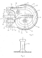
Fig. 1 shows a section view of a first embodiment of a beverage dispensing machine heater according to the invention; -
Fig. 2 shows a bottom view of the heater infigure 1 ; -
Fig. 3 shows a connection lip at the openings of the container seen infigure 1 ; -
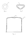
Fig. 4 shows a circular section of a serpentine; -
Fig. 5 shows the section of the serpentine infigure 4 after pressing it; -
Fig. 6 shows a cap belonging to the container infigure 1 ; -
Fig. 7 shows a section view of a second embodiment of a beverage dispensing machine heater according to the invention; -
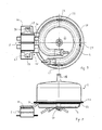
Fig. 8 shows a side view of a third embodiment of a beverage dispensing machine heater according to the invention; -
Fig. 9 shows a bottom view of the heater infigure 8 ; -
Fig. 10 shows a perspective bottom view of the heater infigure 8 . - The same reference numbers artd letters in the drawings refer to the same elements or components.
- The heater of a hot beverage dispensing machine, object of the present invention, according to
figures 1 and7 , comprises acontainer 2 filled with aliquid 3, which in the specific example is water. Anelectric heating resistor 4, best seen infigure 2 , is arranged outside on the base ofcontainer 2, which resistor heats theliquid 3 within the container itself. - In a first variant, a heating water circuit segment or
pipe 10, possibly comprising a spiral-shaped segment 11, i.e. a segment wound as a spiral, is immersed inliquid 3. Theends water circuit segment 10 are adapted to be connected to an external circuit, through which a further liquid to be heated circulates. In particular, theend 12 for introducing the liquid to be heated preferably crosses the base ofcontainer 2, i.e. it is on the same side as theelectric resistor 4 when suitably orientating the heater for working.Extremities container 2 from opposite sides. - Hence, said heating
water circuit segment 10 is indirectly heated by means ofliquid 3 which acts as a heat transmission means. Theliquid 3 is indirectly heated through the base ofcontainer 2, with which theelectric resistor 4 is externally associated. - A second advantageous variant does not provide for the presence of the heating circuit water segment or
pipe 10 immersed in theliquid 3 within thecontainer 2. Also in this case, theliquid 3 is indirectly heated through the base ofcontainer 2. - In both preferred variants, said
resistor 4 is a flat serpentine, intentionally outsidecontainer 2 to avoid saline deposits from being attached directly thereon, which normally determines a more rapid deterioration thereof. - In order to increase the thermal efficiency of heater 1, the serpentine is preferably pressed in the transversal direction:
figures 4 and 5 show a circular-section serpentine and a pressed-section serpentine, respectively. The serpentine is externally attached to the bottom ofcontainer 2, preferably by means of welding-brazing. - According to the preferred embodiments of the invention,
container 2 has a hotfluid outlet opening 2a placed on the upper part of the same with respect to the orientation of the heater in operation, which is typically the wall opposite to that on which theelectric resistor 4 is located. - The hot water or steam which exits the
opening 2a is replaced in the container by other water introduced through theopening 2b, which may be positioned in whatever manner in the container, preferably close toresistor 4, so as to be heated immediately after it is introduced in thecontainer 2. In the variants infigures 1 and7 , theopening 2b is provided on the bottom ofcontainer 2 and is substantially at theopening 2a provided on the upper part ofcontainer 2, opposite to said bottom. Within the container, in front of theopening 2b, a baffle is advantageously arranged to avoid the entering cold fluid from creating a direct flow towards theopening 2a and to favor the fluid mixing in the container. - The introduction of
water 3 may be controlled by means of a probe or level sensor or equivalent means. - With reference to
figures 1 and3 , opening 2a andopening 2b preferably comprise alip - The
container 2 preferably comprises anopen cap 23, occluded to form thecontainer 2 by afirst plate 21, to which asecond plate 22, preferably made of aluminium, aluminium alloy or other good heat conducting material, is externally arranged by the side and welded-brazed.Serpentine 4 is welded-brazed to saidsecond plate 22. - Both the
cap 23 and saidfirst closing plate 21 are preferably made of stainless steel.Cap 23 is obtained by drawing. Thereby, the cap itself is provided with theopening 2a, also obtained by means of the same drawing process. - The
plate 21 to be coupled to close thecap 23 is obtained by shearing and drawing in order to be provided with theopening 2b. - The
electric resistor 4, preferably in the form of a serpentine, is either integrated inplate 22 or fixed thereto by brazing, and is transversally pressed so as to have a substantially flat side to provide a better contact surface with theplate 22. Thereby, the heat exchange betweenheating resistor 4 and fluid in thecontainer 2 is improved. - The
end 12 of the possible pipe orexchanger 10crosses container 2 by means of the opening 26 (Figure 2 ) at theplates - Advantageously, the
plate 22 is conveniently shaped to accommodate heat control and safety devices, comprising a thermostat and a thermal fuse. The particular location of this housing allows to reduce dimensions, both the intrinsic positioning dimensions of the electric resistor and the external dimensions of the heater (e.g. as compared to heaters with internal resistors). Furthermore, the liquid content to be heated may be considerably reduced according to the final working conditions of the heater, thus saving energy. The space inside the container orheater 2 is all usable and further allows to accommodate the heating water circuit segment or pipe orexchanger 10, the dimensioning of which has no geometrical constraint, but is only functional and dictated by the operation in the final apparatus (e.g. a coffee machine). - In a first embodiment of the invention, shown in
Figures 1 and2 , thefirst steel plate 21, defining a first surface which closes thecap 23, is provided with a projection 21' externally protruding from thecap 23. Said projection 21' is arranged on the same surface defined by thefirst plate 21. - The
second plate 22 is fixed by brazing underneath thefirst plate 21, thus defining a second surface parallel to said first surface. - Said
second plate 22 is also provided with a projection 22' radially and externally protruding from thecap 23. Said projection 22' is arranged on the same second surface defined by thesecond plate 22. Advantageously, the projection 22' of the second plate 22' is at the projection 21' of thefirst plate 21 and has a smaller surface than said projection 21'. - As shown in
Figure 2 , theelectric resistor 4 is either integrated with or fixed to thesecond plate 22, e.g. by means of welding-brazing and/or by means ofappropriate folds 27 ofplate 22, in order to centre theresistor 4 with respect to thecap 23. The heat control andsafety devices 5, comprising a thermostat and a thermal fuse, are advantageously accommodated on the projection 22'. The casing containing the thermostat and the thermal fuse is advantageously provided with simple side flaps 28 which are fixed to the projection 22' of thesecond plate 22 by means of appropriate fastening means, e.g. by means of screws (not shown), at appropriate fastening points 29. - Such an advantageous solution does not require additional support components of the heat control and safety devices. These devices are normally fixed to further support means, different from the
plates plate 22. This disadvantageously implies a further deterioration of the thermal transmission to the control/safety devices associated with the heater of the beverage dispensing machine, said further supporting means brazed on theplate 22 forming a heating resistor in turn. - This solution further allows an effective coupling between the
cap 23 and thefirst plate 21, both made of steel. Such a coupling facilitates joining edges by means of welding, e.g. laser welding, without requiring mechanical or electric adjustments of the welding apparatus during the operation. - In particular, the first embodiment (
Figures 1 and2 ) is compatible with laser welding because the thermal influence of the steel-steel fusion which generates the laser welding is not so extended to concern the aluminium ofsecond plate 22 and sheath of theelectric resistor 4. - In a second embodiment of the invention, shown in
Figure 7 , thefirst plate 21 made of steel defines a first surface which closes thecap 23 but is not provided with the projection 21', included in the first embodiment of the invention.Plate 21 has a flat shape so as to perfectly close thecap 23 and is welded to thewelding edge 30 of the cap itself. - The
second plate 22 at least partially defining a second surface parallel to said first surface is fixed by brazing underneath thefirst plate 21. - Said
second plate 22 is advantageously provided with a projection 22' radially protruding outwards from thecap 23. Unlike the first embodiment, said projection 22' is not arranged on the same second surface. Advantageously, the projection 22' has afirst portion 31, defining a third inclined surface with respect to said second surface, and asecond portion 32 defining a fourth surface which is substantially parallel to said first and second surfaces. - As shown in
Figure 7 , theelectric resistor 4 is integrated or fixed, e.g. by means of welding-brazing and/or by means ofappropriate flaps 27 ofplate 22, to the part of thesecond plate 22 defining the second surface for centering theresistor 4 with respect to thecap 23. - The heat control and
safety devices 5 comprising a thermostat and a thermal fuse are advantageously accommodated on thesecond portion 32 of protrusion 22'. The casing containing thermostat and thermal fuse is advantageously provided withsimple side flaps 2, 8 which are fixed to saidportion 32 by means of appropriate fastening means, e.g. by means of screws (not shown), at appropriate fastening points 29. - The misalignment of projection 22' from the second surface of
plate 22 advantageously allows to keep the control/safety device at a greater distance form thewelding edge 30 between thecap 23 and thefirst plate 21, in all cases allowing an effective coupling of the edges for a continuous, homogenous welding operation without varying the mechanical and electric setting adjustments of the welding apparatus. - A third embodiment of the invention is shown in Figures from 8 to 10. It substantially corresponds to the second embodiment in
Fig. 7 .Figure 10 shows an upside-down heater to better illustrate the main components according to the present invention. Unlike said second embodiment, this third embodiment does not include theheat exchanger 10 withincontainer 2. - In all three embodiments described above, the temperature of
liquid 3 is adjusted by In all three embodiments described above, the temperature ofliquid 3 is adjusted by the thermostat outside thecontainer 2, which supplies theresistor 4 through the terminals 4a and 4b (seeFig. 2 , in particular).Resistor 4 being outside thecontainer 2 and directly in contact with the thermostat, the thermostat reaction is more immediate and reduces the possibility of overheating. The presence of thealuminium plate 22 interposed between the base ofcontainer 2 and theresistor 4 improves the heat exchange between the heating resistor and the fluid in the container. - The thermostat in turn is adapted to be connected to an external electric source by means of its
terminals 5a and 5b. - In another variant, a temperature sensor (not shown) may be at least partially provided so as to be immersed within the
container 2. - The features disclosed in the preferred embodiments (shown here) may be present as a whole or in part, not altering the innovative concept of the invention. The different embodiments described above may also be combined to one another.
- The advantages of the present invention are apparent:
- it improves heat transmission to the control/safety devices associated with the heater;
- its reduces the global dimensions of said control/safety devices;
- it allows a direct control of the resistor temperature, even if there is no water;
- a heat exchanger may be arranged within the heater for a second function;
- it facilitates the manufacturing of the device of the invention by brazing the resistor on the plates which are then welded on the cap,
- it improves the duration of the heating resistor, because it is placed outside the container, so that said deposits are not directly sedimented thereon and the problem of corrosion is eliminated;
- the fluid level within the container has little influence on the correct operation of the heater because a small amount of fluid which covers the bottom is sufficient for its operation, and also in the case of total lack of fluid, there is a lower risk of overheating;
- the operations of removing lime scale from the device are facilitated and simplified, because the resistor is not in contact with the fluid.
- The specific embodiments described herein do not limit the content of this application which covers all the variants of the invention defined by the claims.
Claims (15)
- A beverage dispensing machine, comprising a liquid heater, said heater being provided with at least:- a container (2), adapted to be at least partially filled with a first liquid (3) to be heated, defined by a cap (23) closed by a first plate (21), wherein said container (2) comprises a first opening (2a) for releasing a portion of the first liquid (3), in the form of liquid or steam, and a second opening (2b) for introducing a further amount of first liquid (3) for replacing the released amount;- a second plate (22) fixed to said first plate (21), outside the container (2);- an electric heating resistor (4), arranged outside the container (2), fixed in contact with said second plate (22), so as to indirectly heat said first liquid through said first and second plates (21, 22);wherein said second plate (22) is provided with a respective projection (22') radially and externally protruding from the cap (23), heat control and safety devices (5) being fixed to said projection (22') connected to said electric resistor (4).
- A machine according to claim 1, wherein said first plate (21) is provided with a respective projection (21'), radially and externally protruding from the cap (23) and arranged on a first surface defined by the first plate (21) itself.
- A machine according to claim 2, wherein said second plate (22) defines a second surface parallel to said first surface.
- A machine according to claim 3, wherein the projection (22') of the second plate (22) is arranged on said second surface.
- A machine according to claim 4, wherein the projection (22') of the second plate (22) Is arranged at the projection (21') of the first plate (21).
- A machine according to claim 1, wherein said first plate (21) defines a first surface and is shaped so as to close the cap (23), being welded to an edge (30) of the cap (23) itself.
- A machine according to claim 6, wherein said second plate (22) at least partially defines a second surface parallel to said first surface.
- A machine according to claim 7, wherein the projection (22') of the second plate (22) comprises a first portion (31), defining a third surface inclined with respect to said second plate, and a second portion (32) defining a fourth surface which is substantially parallel to said first and second surfaces.
- A machine according to claim 8, wherein said heat control and safety devices (5) are accommodated on said second portion (32).
- A machine according to any one of the preceding claims, wherein said thermal control and safety devices (5) comprise at least one thermostat and one thermal fuse.
- A machine according to claim 10, wherein a casing containing the thermostat and the thermal fuse is provided with side flaps (28) fixed to the projection (22') of the second plate (22).
- A machine according to any one of the preceding claims, wherein folds (27) of the second plate (22) are provided for centering the electric resistor (4) with respect to the cap (23).
- A machine according to any one of the preceding claims, wherein the cap (23) and the first plate (21) are made of steel, and wherein said second plate (22) is made of aluminium or aluminium alloys.
- A machine according to any one of the preceding claims, wherein at least one pipe (10) is provided for the passage of a second liquid, said pipe (10) crossing the container (2) so as to be in thermal transmission contact with said first liquid (3), acting as a heat transmitting means, whereby said second liquid is indirectly heated by heating the first liquid (3).
- A machine according to any one of the preceding claims, wherein said opening (2b) is positioned close to resistor 4, so that the water can be heated immediately after it is introduced in container (2).
Applications Claiming Priority (1)
| Application Number | Priority Date | Filing Date | Title |
|---|---|---|---|
| PCT/IB2010/051424 WO2011121395A1 (en) | 2010-04-01 | 2010-04-01 | Beverage dispensing machine |
Publications (2)
| Publication Number | Publication Date |
|---|---|
| EP2552288A1 EP2552288A1 (en) | 2013-02-06 |
| EP2552288B1 true EP2552288B1 (en) | 2014-05-07 |
Family
ID=43242950
Family Applications (1)
| Application Number | Title | Priority Date | Filing Date |
|---|---|---|---|
| EP10718700.7A Active EP2552288B1 (en) | 2010-04-01 | 2010-04-01 | Beverage dispensing machine |
Country Status (4)
| Country | Link |
|---|---|
| US (1) | US9526372B2 (en) |
| EP (1) | EP2552288B1 (en) |
| CN (1) | CN102933124B (en) |
| WO (1) | WO2011121395A1 (en) |
Families Citing this family (8)
| Publication number | Priority date | Publication date | Assignee | Title |
|---|---|---|---|---|
| EP2606784A1 (en) | 2011-12-22 | 2013-06-26 | Nestec S.A. | A heating unit for a beverage preparation machine |
| CN104487781A (en) * | 2012-02-14 | 2015-04-01 | 科尼利斯有限公司 | Hot beverage dispensing system |
| ITPD20130321A1 (en) * | 2013-11-26 | 2015-05-27 | I R C A S P A Ind Resiste Nze Corazzate | THERMOBLOCK FOR HEATING LIQUIDS |
| CN108451365A (en) * | 2018-03-30 | 2018-08-28 | 施金财 | portable coffee machine |
| CN113171299B (en) * | 2019-05-31 | 2022-12-30 | 浙江厚达智能科技股份有限公司 | The upper surface of the top wall of the barrel body is provided with a thickened block which is pulled upwards to form an inclined medicine decocting barrel |
| CN113018191B (en) * | 2019-05-31 | 2022-11-01 | 浙江厚达智能科技股份有限公司 | Hook head pull-down bladeless stirring type medicine decocting barrel with thickened blocks arranged on lower surface of bottom wall of barrel body |
| IT201900012945A1 (en) * | 2019-07-25 | 2021-01-25 | Simonelli Group Spa | HEAT EXCHANGER FOR DISCHARGE TANKS OF SOLENOID VALVES OF COFFEE DISPENSING MACHINES, RELATIVE DRAIN TANK FITTED WITH THIS HEAT EXCHANGER AND MACHINE FOR DISPENSING COFFEE EQUIPPED WITH THIS DISCHARGE TANK AND THERMAL EXCHANGER. |
| CN110477757A (en) * | 2019-07-26 | 2019-11-22 | 丹顶鹤智能科技(江苏)有限公司 | It is a kind of can multi-mode heating liquid heating boiler |
Citations (2)
| Publication number | Priority date | Publication date | Assignee | Title |
|---|---|---|---|---|
| GB2330402A (en) * | 1997-10-17 | 1999-04-21 | Moulinex Sa | Water heater or steam generator with electrical heating element |
| US20090293734A1 (en) * | 2006-07-11 | 2009-12-03 | Koninklijke Philips Electronics N.V. | Beverage maker having a thermostat for controlling the operation of heating means for heating water |
Family Cites Families (15)
| Publication number | Priority date | Publication date | Assignee | Title |
|---|---|---|---|---|
| DE2808182A1 (en) | 1978-02-25 | 1979-08-30 | Czepek & Co | Continuous electric heater for coffee and tea makers - has automatic rapid cut=out when running empty, but allows continuous heating until boiling occurs |
| US4147925A (en) * | 1978-04-26 | 1979-04-03 | Kidde Consumer Durables Corp. | Percolator partition plate heater assembly |
| US4356381A (en) * | 1980-10-01 | 1982-10-26 | Scovill Inc. | Warming plate mounting arrangement in a single-pass drip-type electric coffeemaker |
| DE3374537D1 (en) * | 1982-09-24 | 1987-12-23 | Onofrio Rocchitelli | Heating device for the glass washing fluid of motor vehicles and the like |
| WO1987004910A1 (en) * | 1986-02-18 | 1987-08-27 | Numa Nuove Macchine S.R.L. | Process for the fast cooking of pasta and the like and apparatus to put the process into practice |
| NL8801182A (en) * | 1987-10-01 | 1989-05-01 | Interconnection B V | HEATING ELEMENT. |
| CN1143595C (en) * | 1994-06-09 | 2004-03-24 | 施特里克斯有限公司 | Thermal sensitive controller for boiling water vessel |
| DE69520563D1 (en) | 1994-12-13 | 2001-05-10 | Strix Ltd | VESSELS FOR HEATING LIQUIDS |
| IT1297492B1 (en) | 1997-10-01 | 1999-12-17 | I R C A Spa Ind Resistenze Cor | HEATING ELEMENT FOR HOUSEHOLD APPLIANCES. |
| WO2001041508A1 (en) * | 1999-11-30 | 2001-06-07 | Ibiden Co., Ltd. | Ceramic heater |
| US6184500B1 (en) * | 2000-03-10 | 2001-02-06 | Homedics, Inc. | Paraffin bath |
| DE20208346U1 (en) * | 2002-05-28 | 2002-08-14 | Hoberg Haushaltswarenhandelsgm | Heated component |
| GB2399735B (en) * | 2003-03-25 | 2006-04-26 | Strix Ltd | Electric liquid boiling appliances |
| KR100770641B1 (en) * | 2006-05-26 | 2007-10-30 | 김홍배 | Indirect heating cooking device |
| CN201153865Y (en) * | 2008-01-25 | 2008-11-26 | 丁国威 | Slurry heating barrel |
-
2010
- 2010-04-01 CN CN201080065983.7A patent/CN102933124B/en active Active
- 2010-04-01 WO PCT/IB2010/051424 patent/WO2011121395A1/en not_active Ceased
- 2010-04-01 US US13/638,391 patent/US9526372B2/en active Active
- 2010-04-01 EP EP10718700.7A patent/EP2552288B1/en active Active
Patent Citations (2)
| Publication number | Priority date | Publication date | Assignee | Title |
|---|---|---|---|---|
| GB2330402A (en) * | 1997-10-17 | 1999-04-21 | Moulinex Sa | Water heater or steam generator with electrical heating element |
| US20090293734A1 (en) * | 2006-07-11 | 2009-12-03 | Koninklijke Philips Electronics N.V. | Beverage maker having a thermostat for controlling the operation of heating means for heating water |
Also Published As
| Publication number | Publication date |
|---|---|
| US9526372B2 (en) | 2016-12-27 |
| US20130025468A1 (en) | 2013-01-31 |
| EP2552288A1 (en) | 2013-02-06 |
| WO2011121395A8 (en) | 2012-03-22 |
| CN102933124A (en) | 2013-02-13 |
| WO2011121395A1 (en) | 2011-10-06 |
| CN102933124B (en) | 2016-10-26 |
Similar Documents
| Publication | Publication Date | Title |
|---|---|---|
| US9526372B2 (en) | Beverage dispensing machine | |
| EP2515728B1 (en) | Flow heaters | |
| RU2536221C2 (en) | Heating device | |
| JP4959332B2 (en) | Liquid heating device for home appliance, home appliance equipped with the device | |
| US20140233928A1 (en) | Flow heaters | |
| EP2218374A2 (en) | Integrated heater for a beverage preparation device | |
| WO2014195842A2 (en) | A device and a method for the preparation of hot liquid or steam | |
| EP1928284B1 (en) | Device for making a beverage, provided with a water boiler | |
| WO2019171310A1 (en) | A flow heater for heating fluid and/or for generating steam, and a heater assembly and a flow device for heating fluid and/or for generating steam comprising such a heater | |
| GB2484321A (en) | A thick film heater/ heat dissipater assembly associate with a flow heater flow channel. | |
| US20090293734A1 (en) | Beverage maker having a thermostat for controlling the operation of heating means for heating water | |
| EP1381299B1 (en) | Electric heaters | |
| EP1388313B1 (en) | Electric beverage maker | |
| US20080212954A1 (en) | Flow-through heater | |
| EP2363049A2 (en) | Heaters for liquid heating vessels | |
| CN202262843U (en) | Water heating device for household appliance | |
| JP2007315647A (en) | Fluid heater and control device of fluid heater | |
| JP3105338U (en) | Electromagnetic induction heating device and liquid distribution unit used for the same | |
| GB2363703A (en) | A heating element with a brazed connection to a water tube | |
| ITRM20080520A1 (en) | LIQUID BOILER |
Legal Events
| Date | Code | Title | Description |
|---|---|---|---|
| PUAI | Public reference made under article 153(3) epc to a published international application that has entered the european phase |
Free format text: ORIGINAL CODE: 0009012 |
|
| 17P | Request for examination filed |
Effective date: 20121030 |
|
| AK | Designated contracting states |
Kind code of ref document: A1 Designated state(s): AT BE BG CH CY CZ DE DK EE ES FI FR GB GR HR HU IE IS IT LI LT LU LV MC MK MT NL NO PL PT RO SE SI SK SM TR |
|
| DAX | Request for extension of the european patent (deleted) | ||
| GRAP | Despatch of communication of intention to grant a patent |
Free format text: ORIGINAL CODE: EPIDOSNIGR1 |
|
| INTG | Intention to grant announced |
Effective date: 20131112 |
|
| GRAS | Grant fee paid |
Free format text: ORIGINAL CODE: EPIDOSNIGR3 |
|
| GRAA | (expected) grant |
Free format text: ORIGINAL CODE: 0009210 |
|
| AK | Designated contracting states |
Kind code of ref document: B1 Designated state(s): AT BE BG CH CY CZ DE DK EE ES FI FR GB GR HR HU IE IS IT LI LT LU LV MC MK MT NL NO PL PT RO SE SI SK SM TR |
|
| REG | Reference to a national code |
Ref country code: GB Ref legal event code: FG4D |
|
| REG | Reference to a national code |
Ref country code: AT Ref legal event code: REF Ref document number: 665905 Country of ref document: AT Kind code of ref document: T Effective date: 20140515 |
|
| REG | Reference to a national code |
Ref country code: IE Ref legal event code: FG4D |
|
| REG | Reference to a national code |
Ref country code: DE Ref legal event code: R096 Ref document number: 602010015845 Country of ref document: DE Effective date: 20140618 |
|
| REG | Reference to a national code |
Ref country code: AT Ref legal event code: MK05 Ref document number: 665905 Country of ref document: AT Kind code of ref document: T Effective date: 20140507 |
|
| REG | Reference to a national code |
Ref country code: NL Ref legal event code: VDEP Effective date: 20140507 |
|
| REG | Reference to a national code |
Ref country code: LT Ref legal event code: MG4D |
|
| PG25 | Lapsed in a contracting state [announced via postgrant information from national office to epo] |
Ref country code: LT Free format text: LAPSE BECAUSE OF FAILURE TO SUBMIT A TRANSLATION OF THE DESCRIPTION OR TO PAY THE FEE WITHIN THE PRESCRIBED TIME-LIMIT Effective date: 20140507 Ref country code: GR Free format text: LAPSE BECAUSE OF FAILURE TO SUBMIT A TRANSLATION OF THE DESCRIPTION OR TO PAY THE FEE WITHIN THE PRESCRIBED TIME-LIMIT Effective date: 20140808 Ref country code: FI Free format text: LAPSE BECAUSE OF FAILURE TO SUBMIT A TRANSLATION OF THE DESCRIPTION OR TO PAY THE FEE WITHIN THE PRESCRIBED TIME-LIMIT Effective date: 20140507 Ref country code: NO Free format text: LAPSE BECAUSE OF FAILURE TO SUBMIT A TRANSLATION OF THE DESCRIPTION OR TO PAY THE FEE WITHIN THE PRESCRIBED TIME-LIMIT Effective date: 20140807 Ref country code: IS Free format text: LAPSE BECAUSE OF FAILURE TO SUBMIT A TRANSLATION OF THE DESCRIPTION OR TO PAY THE FEE WITHIN THE PRESCRIBED TIME-LIMIT Effective date: 20140907 Ref country code: CY Free format text: LAPSE BECAUSE OF FAILURE TO SUBMIT A TRANSLATION OF THE DESCRIPTION OR TO PAY THE FEE WITHIN THE PRESCRIBED TIME-LIMIT Effective date: 20140507 |
|
| PG25 | Lapsed in a contracting state [announced via postgrant information from national office to epo] |
Ref country code: ES Free format text: LAPSE BECAUSE OF FAILURE TO SUBMIT A TRANSLATION OF THE DESCRIPTION OR TO PAY THE FEE WITHIN THE PRESCRIBED TIME-LIMIT Effective date: 20140507 Ref country code: SE Free format text: LAPSE BECAUSE OF FAILURE TO SUBMIT A TRANSLATION OF THE DESCRIPTION OR TO PAY THE FEE WITHIN THE PRESCRIBED TIME-LIMIT Effective date: 20140507 Ref country code: HR Free format text: LAPSE BECAUSE OF FAILURE TO SUBMIT A TRANSLATION OF THE DESCRIPTION OR TO PAY THE FEE WITHIN THE PRESCRIBED TIME-LIMIT Effective date: 20140507 Ref country code: AT Free format text: LAPSE BECAUSE OF FAILURE TO SUBMIT A TRANSLATION OF THE DESCRIPTION OR TO PAY THE FEE WITHIN THE PRESCRIBED TIME-LIMIT Effective date: 20140507 Ref country code: LV Free format text: LAPSE BECAUSE OF FAILURE TO SUBMIT A TRANSLATION OF THE DESCRIPTION OR TO PAY THE FEE WITHIN THE PRESCRIBED TIME-LIMIT Effective date: 20140507 Ref country code: PL Free format text: LAPSE BECAUSE OF FAILURE TO SUBMIT A TRANSLATION OF THE DESCRIPTION OR TO PAY THE FEE WITHIN THE PRESCRIBED TIME-LIMIT Effective date: 20140507 |
|
| PG25 | Lapsed in a contracting state [announced via postgrant information from national office to epo] |
Ref country code: PT Free format text: LAPSE BECAUSE OF FAILURE TO SUBMIT A TRANSLATION OF THE DESCRIPTION OR TO PAY THE FEE WITHIN THE PRESCRIBED TIME-LIMIT Effective date: 20140908 |
|
| PG25 | Lapsed in a contracting state [announced via postgrant information from national office to epo] |
Ref country code: RO Free format text: LAPSE BECAUSE OF FAILURE TO SUBMIT A TRANSLATION OF THE DESCRIPTION OR TO PAY THE FEE WITHIN THE PRESCRIBED TIME-LIMIT Effective date: 20140507 Ref country code: DK Free format text: LAPSE BECAUSE OF FAILURE TO SUBMIT A TRANSLATION OF THE DESCRIPTION OR TO PAY THE FEE WITHIN THE PRESCRIBED TIME-LIMIT Effective date: 20140507 Ref country code: EE Free format text: LAPSE BECAUSE OF FAILURE TO SUBMIT A TRANSLATION OF THE DESCRIPTION OR TO PAY THE FEE WITHIN THE PRESCRIBED TIME-LIMIT Effective date: 20140507 Ref country code: CZ Free format text: LAPSE BECAUSE OF FAILURE TO SUBMIT A TRANSLATION OF THE DESCRIPTION OR TO PAY THE FEE WITHIN THE PRESCRIBED TIME-LIMIT Effective date: 20140507 Ref country code: SK Free format text: LAPSE BECAUSE OF FAILURE TO SUBMIT A TRANSLATION OF THE DESCRIPTION OR TO PAY THE FEE WITHIN THE PRESCRIBED TIME-LIMIT Effective date: 20140507 Ref country code: BE Free format text: LAPSE BECAUSE OF FAILURE TO SUBMIT A TRANSLATION OF THE DESCRIPTION OR TO PAY THE FEE WITHIN THE PRESCRIBED TIME-LIMIT Effective date: 20140507 |
|
| REG | Reference to a national code |
Ref country code: DE Ref legal event code: R097 Ref document number: 602010015845 Country of ref document: DE |
|
| PG25 | Lapsed in a contracting state [announced via postgrant information from national office to epo] |
Ref country code: NL Free format text: LAPSE BECAUSE OF FAILURE TO SUBMIT A TRANSLATION OF THE DESCRIPTION OR TO PAY THE FEE WITHIN THE PRESCRIBED TIME-LIMIT Effective date: 20140507 |
|
| PLBE | No opposition filed within time limit |
Free format text: ORIGINAL CODE: 0009261 |
|
| STAA | Information on the status of an ep patent application or granted ep patent |
Free format text: STATUS: NO OPPOSITION FILED WITHIN TIME LIMIT |
|
| 26N | No opposition filed |
Effective date: 20150210 |
|
| REG | Reference to a national code |
Ref country code: DE Ref legal event code: R097 Ref document number: 602010015845 Country of ref document: DE Effective date: 20150210 |
|
| PG25 | Lapsed in a contracting state [announced via postgrant information from national office to epo] |
Ref country code: SI Free format text: LAPSE BECAUSE OF FAILURE TO SUBMIT A TRANSLATION OF THE DESCRIPTION OR TO PAY THE FEE WITHIN THE PRESCRIBED TIME-LIMIT Effective date: 20140507 |
|
| PG25 | Lapsed in a contracting state [announced via postgrant information from national office to epo] |
Ref country code: LU Free format text: LAPSE BECAUSE OF FAILURE TO SUBMIT A TRANSLATION OF THE DESCRIPTION OR TO PAY THE FEE WITHIN THE PRESCRIBED TIME-LIMIT Effective date: 20150401 Ref country code: MC Free format text: LAPSE BECAUSE OF FAILURE TO SUBMIT A TRANSLATION OF THE DESCRIPTION OR TO PAY THE FEE WITHIN THE PRESCRIBED TIME-LIMIT Effective date: 20140507 |
|
| REG | Reference to a national code |
Ref country code: CH Ref legal event code: PL |
|
| REG | Reference to a national code |
Ref country code: IE Ref legal event code: MM4A |
|
| PG25 | Lapsed in a contracting state [announced via postgrant information from national office to epo] |
Ref country code: LI Free format text: LAPSE BECAUSE OF NON-PAYMENT OF DUE FEES Effective date: 20150430 Ref country code: CH Free format text: LAPSE BECAUSE OF NON-PAYMENT OF DUE FEES Effective date: 20150430 |
|
| REG | Reference to a national code |
Ref country code: FR Ref legal event code: PLFP Year of fee payment: 7 |
|
| PG25 | Lapsed in a contracting state [announced via postgrant information from national office to epo] |
Ref country code: IE Free format text: LAPSE BECAUSE OF NON-PAYMENT OF DUE FEES Effective date: 20150401 |
|
| REG | Reference to a national code |
Ref country code: DE Ref legal event code: R082 Ref document number: 602010015845 Country of ref document: DE Representative=s name: SCHWABE SANDMAIR MARX PATENTANWAELTE RECHTSANW, DE Ref country code: DE Ref legal event code: R082 Ref document number: 602010015845 Country of ref document: DE Representative=s name: SSM SANDMAIR PATENTANWAELTE RECHTSANWALT PARTN, DE |
|
| PG25 | Lapsed in a contracting state [announced via postgrant information from national office to epo] |
Ref country code: MT Free format text: LAPSE BECAUSE OF FAILURE TO SUBMIT A TRANSLATION OF THE DESCRIPTION OR TO PAY THE FEE WITHIN THE PRESCRIBED TIME-LIMIT Effective date: 20140507 |
|
| REG | Reference to a national code |
Ref country code: FR Ref legal event code: PLFP Year of fee payment: 8 |
|
| PG25 | Lapsed in a contracting state [announced via postgrant information from national office to epo] |
Ref country code: HU Free format text: LAPSE BECAUSE OF FAILURE TO SUBMIT A TRANSLATION OF THE DESCRIPTION OR TO PAY THE FEE WITHIN THE PRESCRIBED TIME-LIMIT; INVALID AB INITIO Effective date: 20100401 Ref country code: SM Free format text: LAPSE BECAUSE OF FAILURE TO SUBMIT A TRANSLATION OF THE DESCRIPTION OR TO PAY THE FEE WITHIN THE PRESCRIBED TIME-LIMIT Effective date: 20140507 Ref country code: BG Free format text: LAPSE BECAUSE OF FAILURE TO SUBMIT A TRANSLATION OF THE DESCRIPTION OR TO PAY THE FEE WITHIN THE PRESCRIBED TIME-LIMIT Effective date: 20140507 |
|
| PG25 | Lapsed in a contracting state [announced via postgrant information from national office to epo] |
Ref country code: TR Free format text: LAPSE BECAUSE OF FAILURE TO SUBMIT A TRANSLATION OF THE DESCRIPTION OR TO PAY THE FEE WITHIN THE PRESCRIBED TIME-LIMIT Effective date: 20140507 |
|
| REG | Reference to a national code |
Ref country code: FR Ref legal event code: PLFP Year of fee payment: 9 |
|
| PG25 | Lapsed in a contracting state [announced via postgrant information from national office to epo] |
Ref country code: MK Free format text: LAPSE BECAUSE OF FAILURE TO SUBMIT A TRANSLATION OF THE DESCRIPTION OR TO PAY THE FEE WITHIN THE PRESCRIBED TIME-LIMIT Effective date: 20140507 |
|
| P01 | Opt-out of the competence of the unified patent court (upc) registered |
Effective date: 20230525 |
|
| PGFP | Annual fee paid to national office [announced via postgrant information from national office to epo] |
Ref country code: DE Payment date: 20250422 Year of fee payment: 16 |
|
| PGFP | Annual fee paid to national office [announced via postgrant information from national office to epo] |
Ref country code: GB Payment date: 20250423 Year of fee payment: 16 |
|
| PGFP | Annual fee paid to national office [announced via postgrant information from national office to epo] |
Ref country code: IT Payment date: 20250424 Year of fee payment: 16 |
|
| PGFP | Annual fee paid to national office [announced via postgrant information from national office to epo] |
Ref country code: FR Payment date: 20250425 Year of fee payment: 16 |