EP2552051A1 - Management of power consumption in a radio communication network - Google Patents
Management of power consumption in a radio communication network Download PDFInfo
- Publication number
- EP2552051A1 EP2552051A1 EP11305992A EP11305992A EP2552051A1 EP 2552051 A1 EP2552051 A1 EP 2552051A1 EP 11305992 A EP11305992 A EP 11305992A EP 11305992 A EP11305992 A EP 11305992A EP 2552051 A1 EP2552051 A1 EP 2552051A1
- Authority
- EP
- European Patent Office
- Prior art keywords
- state
- connection path
- con1
- link
- capacity
- Prior art date
- Legal status (The legal status is an assumption and is not a legal conclusion. Google has not performed a legal analysis and makes no representation as to the accuracy of the status listed.)
- Granted
Links
- 238000004891 communication Methods 0.000 title claims abstract description 70
- 238000000034 method Methods 0.000 claims abstract description 36
- 230000005540 biological transmission Effects 0.000 claims description 26
- 239000000969 carrier Substances 0.000 claims description 10
- 230000003044 adaptive effect Effects 0.000 claims description 4
- 238000004590 computer program Methods 0.000 claims description 2
- 230000008859 change Effects 0.000 description 35
- 230000006870 function Effects 0.000 description 11
- 101100393235 Caenorhabditis elegans gon-1 gene Proteins 0.000 description 5
- 238000007726 management method Methods 0.000 description 4
- 230000002411 adverse Effects 0.000 description 3
- 230000007423 decrease Effects 0.000 description 3
- 238000010586 diagram Methods 0.000 description 3
- 230000036039 immunity Effects 0.000 description 3
- 230000002457 bidirectional effect Effects 0.000 description 2
- 238000005562 fading Methods 0.000 description 2
- 230000008569 process Effects 0.000 description 2
- 230000009471 action Effects 0.000 description 1
- 230000015556 catabolic process Effects 0.000 description 1
- 238000006731 degradation reaction Methods 0.000 description 1
- 230000007613 environmental effect Effects 0.000 description 1
- 238000009434 installation Methods 0.000 description 1
- 238000012544 monitoring process Methods 0.000 description 1
- 238000012913 prioritisation Methods 0.000 description 1
- 230000009467 reduction Effects 0.000 description 1
- 230000007704 transition Effects 0.000 description 1
- 230000001960 triggered effect Effects 0.000 description 1
Images


Classifications
-
- H—ELECTRICITY
- H04—ELECTRIC COMMUNICATION TECHNIQUE
- H04L—TRANSMISSION OF DIGITAL INFORMATION, e.g. TELEGRAPHIC COMMUNICATION
- H04L12/00—Data switching networks
- H04L12/02—Details
- H04L12/12—Arrangements for remote connection or disconnection of substations or of equipment thereof
-
- H—ELECTRICITY
- H04—ELECTRIC COMMUNICATION TECHNIQUE
- H04W—WIRELESS COMMUNICATION NETWORKS
- H04W52/00—Power management, e.g. Transmission Power Control [TPC] or power classes
- H04W52/02—Power saving arrangements
- H04W52/0203—Power saving arrangements in the radio access network or backbone network of wireless communication networks
-
- Y—GENERAL TAGGING OF NEW TECHNOLOGICAL DEVELOPMENTS; GENERAL TAGGING OF CROSS-SECTIONAL TECHNOLOGIES SPANNING OVER SEVERAL SECTIONS OF THE IPC; TECHNICAL SUBJECTS COVERED BY FORMER USPC CROSS-REFERENCE ART COLLECTIONS [XRACs] AND DIGESTS
- Y02—TECHNOLOGIES OR APPLICATIONS FOR MITIGATION OR ADAPTATION AGAINST CLIMATE CHANGE
- Y02D—CLIMATE CHANGE MITIGATION TECHNOLOGIES IN INFORMATION AND COMMUNICATION TECHNOLOGIES [ICT], I.E. INFORMATION AND COMMUNICATION TECHNOLOGIES AIMING AT THE REDUCTION OF THEIR OWN ENERGY USE
- Y02D30/00—Reducing energy consumption in communication networks
- Y02D30/70—Reducing energy consumption in communication networks in wireless communication networks
Definitions
- the present invention generally relates to the field of radio communication networks.
- the present invention relates to the management of power consumption in a radio communication network.
- a radio communication network typically comprises a plurality of nodes connected by radio links. Two nodes of the radio communication network exchange information in the form of a data flow (usually in the form of a stream of bits) modulating a radio signal.
- the number of transmitted bits in the time unit over a radio link is typically referred to as the "data transmission rate” or “data transmission capacity” or simply “capacity” of the radio link.
- Different modulation and coding schemes are capable of achieving different capacities.
- the radio signal is affected by the propagation conditions over the radio link.
- the propagation conditions on the radio link depend on the weather conditions, the presence/absence of interferences, the presence/absence of multi-paths, and so on.
- Adverse propagation conditions i.e. bad weather, presence of interferences, presence of multi-paths
- the receiver may not correctly retrieve the data flow from the received signal and the bit error rate (BER) of the data flow accordingly increases.
- BER bit error rate
- ACM Adaptive Coding Modulation technique
- the transmitter typically receives from the receiver a control signal indicating the conditions of the radio link, and according to this control signal dynamically modifies the modulation and/or coding of the radio signal.
- modulation and coding schemes with the highest available data transmission capacity are usually used. Typical examples of such schemes are 16-QAM, 64-QAM, or 256-QAM (Quadrature Amplitude Modulation). Indeed, the higher the number of constellation points or symbols for a given modulation scheme, the higher the number of bits per symbol transported by the signal and hence the higher the data transmission capacity, at the expense of a lower noise immunity. On the contrary, if the propagation conditions of the radio link get worse (e.g. when fog, rain or snow is present on the radio link), one typically uses a modulation and coding scheme with a greater noise immunity and lower capacity, e.g. 4-QAM.
- a known technique allowing to reduce the power transmitted by a network node is the so-called Automatic Transmitter Power Control (ATPC).
- ATPC Automatic Transmitter Power Control
- Such technique provides for adjusting the output power at the transmitting end of a radio link by monitoring the power of the signal detected at the receiving end of the link.
- the ATPC when the signal propagates on the radio link in good conditions, e.g. good weather, the output power of the transmitter is maintained at a value which is typically lower that its maximum value.
- the ATPC provides for increasing the output power of the transmitter up to a maximum value, so as to ensure that the received signal is above the threshold which guarantees an acceptable bit error rate.
- a radio communication network implementing the ACM technique
- modulation and coding schemes achieving the highest capacity (i.e. the modulation schemes comprising the highest number of constellation points) are usually used and the full available capacity of the radio links is exploited.
- the power consumption of the network is directly related to the modulation scheme used, namely it increases as the number of constellation points increases. Accordingly, in good propagation conditions, the maximum power consumption is reached.
- the ATPC technique is implemented within the radio communication network in conjunction with the ACM technique, the reduction/increase of the transmitter's power according to ATPC is triggered only by the level of the signal detected at the receiver, and accordingly the actual amount of data to be transmitted over the radio link is not taken into account. Disadvantageously, this may lead to a not efficient exploitation of the capacity of the links and to a not optimized power consumption.
- the inventors have addressed the problem of providing a method for managing the power consumption in a radio communication network, which allows optimising the power consumption and, at the same time, efficiently exploiting the capacity of the network radio links.
- embodiments of the present invention provide a method for managing a power consumption of a radio communication network, the radio communication network comprising at least two nodes and a connection path for connecting the at least two nodes under propagation conditions of the connection path, the method comprising:
- propagation conditions will indicate the conditions under which propagation of a radio signal takes place over a radio link.
- the propagation conditions comprise one or more of: the weather conditions over the radio link, the presence/absence of interferences, the presence/absence of multi-paths, and so on.
- a state matching the propagation conditions of the connection path is understood as meaning that, when the connection path is brought to (namely, is operated in accordance with) such state, each radio link of the connection path has a given configuration, namely a given operational state (ON/OFF), a given modulation scheme, a given coding scheme and so on, in such a way so as to guarantee a reliable data transmission over the connection path under that propagation conditions.
- the selected state has a minimum state capacity amongst the states having a state capacity higher than or equal to the capacity associated to the traffic.
- each state of the set of states of the connection path is indicative of a possible configuration of one or more links comprised in the connection path, the possible configuration comprising, for each of the one or more links, one or more of:
- the request is indicative of a variation in the capacity associated to said traffic.
- the request is indicative of a variation in the propagation conditions.
- the request is indicative of a variation in the power consumption of the connection path.
- the request is indicative of a failure affecting the connection path.
- the operating is performed by using at least one adaptive code modulation function and/or at least one automatic transmitter power control function of the nodes.
- embodiments of the present invention provide a computer program product comprising computer-executable instructions for performing, when the program is run on a computer, the steps of the method as set forth above.
- embodiments of the present invention provide a link manager for a radio communication network comprising at least two nodes and a connection path for connecting the at least two nodes under propagation conditions of the connection path, the link manager being configured to:
- the link manager is implemented at a node of the radio communication network.
- the link manager is implemented at an apparatus connected to a node of the radio communication network.
- the present invention provides a radio communication network comprising at least two nodes and a connection path for connecting the at least two nodes under propagation conditions of the connection path, the radio communication network further comprising a link manager as set forth above.
- the communication network further comprises a network manager configured to:
- FIG. 1 schematically shows a radio communication network CN (in the following description referred to also as “communication network CN”) suitable for implementing the method according to a preferred embodiment of the present invention.
- the radio communication network CN comprises a number of network nodes.
- the network nodes are interconnected by means of connection paths, each connection path comprising either a single radio link or a number of parallel radio links (in the following referred to as "links").
- Each link of a connection path is terminated at its opposite ends by a transmitter and a receiver (or by two transceivers, if the link is bidirectional).
- connection paths comprising either a single radio link or a number of parallel radio links (in the following referred to as "links").
- Each link of a connection path is terminated at its opposite ends by a transmitter and a receiver (or by two transceivers, if the link is bidirectional).
- FIG 1 for sake of simplicity, five nodes N1, ... N5 are shown and five connection paths Gon1, ... Con5 connecting them according to a partially meshed topology.
- nodes N1 and N2 are interconnected by means of a connection path Con1.
- the nodes of the communication network CN may be configured to implement the Adaptive Coding Modulation (ACM) technique.
- ACM Adaptive Coding Modulation
- the nodes of the communication network CN are configured to implement the ACM technique in conjunction with the Automatic Transmitter Power Control (ATPC) technique.
- ACM Adaptive Coding Modulation
- ATPC Automatic Transmitter Power Control
- the communication network CN may optionally comprise one or more link managers and a network manager NM cooperating with the nodes of the communication network CN.
- Each link manager is configured to perform management functions upon the link(s) of a connection path of the communication network CN.
- the link manager is configured to cooperate with the nodes of the communication network CN connected by that connection path.
- Figure 1 shows, by way of non limiting example, only one link manger LM configured to perform management functions upon connection path Con1 and therefore to cooperate with node N1 and node N2.
- the link manager LM may be implemented as a stand-alone apparatus connected to any one of the nodes N1, N2.
- the link manager LM is connected to node N1.
- the link manager LM may be integrated within one of nodes N1, N2, for instance node N1.
- the function of the link manager LM may be distributed at both the nodes N1, N2.
- the network manager NM is adapted to perform management functions upon the links of all the connection paths Con1, ... Con5 of the communication network CN.
- the network manager NM is therefore configured to cooperate with all the nodes N1,... N5 of the communication network CN and with all the link managers of the communication network CN.
- the network manager NM may be implemented as a stand-alone apparatus connected either to any one of the nodes N1,... N5 or to any one of the link managers. In Figure 1 , by way of non limiting example, the network manager NM is connected to the link manager LM of the connection path Gon1.
- the communication network CN connects a plurality of users which exchange data through the nodes N1,... N5 of the network CN.
- the data are carried over the connection paths Con1, ... Con5, each connection path Con1, ... Con5 operating at a respective capacity (i.e. a respective data transmission rate).
- the data exchanged between the network nodes N1,... N5 may carry different services, each of them being associated to a respective Quality of Service (QoS).
- QoS Quality of Service
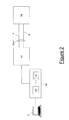
- Figure 2 shows a portion of the communication network CN, comprising the nodes N1, N2, the connection path Con1 and the link manager LM.
- the connection path Con 1 comprises two links A, B. Both the links A, B may be full-duplex links allowing a bidirectional exchange of information between nodes N1, N2. It is assumed that both the links A, B are able to support the transmission of digitally modulated data at a symbol rate equal to C symbol/s.
- the symbol rate represents the number of transmitted symbols per second, the symbol being an integer number of bits equal to or higher than 1.
- a terminal T may be optionally connected to the link manager LM.
- the terminal T preferably comprises a keyboard and a display.
- the terminal T allows an operator responsible of managing the network to interact with the link manager LM, as it will be described in further detail herein after.
- the link manager LM preferably comprises a control module CM and a state table ST.
- the control module CM is preferably implemented by means of a dedicated hardware component, or by means of a hardware component capable of executing a software, in combination with a dedicated software, or by means of a dedicated software component.
- the state table ST preferably comprises information indicative of a set of possible states in which the connection path Con1 may operate.
- the state table ST is preferably generated by the control module CM of the link manager LM, as it will be described in detail herein after.
- Each link configuration preferably comprise one or more of the following parameters:
- the link power consumption of a link comprises the power consumed by the radio interfaces terminating that link at the network nodes N1, N2 and the power emitted by the antennas at the nodes N1, N2 for transmitting the radio signals carrying the data over the link.
- the possible link configurations of the links A, B may differ only by operational state (namely, ON or OFF) and modulation scheme of the link.
- the coding scheme, the number of independent RF carriers, the frequency of the RF carriers, etc. of the links A, B are fixed.
- the supported modulation schemes, the coding scheme, the number of independent RF carriers, the frequency of the RF carriers, etc. are the same on the links A, B of the connection path Con1. In other words, the links A, B of the connection path Con1 are interchangeable.
- each link A, B in operational state ON may be configured to transmit with a 4-QAM, 16-QAM or 64-QAM modulation scheme.
- each link A, B has four possible link configurations:
- any modulation scheme may be adopted over the first and second links A, B.
- the 4-QAM, 16-QAM or 64-QAM modulation schemes allow achieving, on each link, a link capacity of 2xC Mb/s, 4xC Mb/s and 6xC Mb/s with a link power consumption of 5.06 W, 5.38 W and 7.39 W, respectively.
- the operator responsible of managing the network may then provide a plurality of connection configurations or states for the connection path Con1, each state comprising a respective combination of link configurations of the links A, B. For instance:
- the operator preferably determines a respective state capacity as a sum of the link capacities of the links A, B. More than one state may achieve the same state capacity, as it will be discussed in further detail herein after. For instance, both the second state (link A in operational state ON, 16-QAM and link B in operational state OFF) and the fourth state (link A in operational state ON, 4-QAM and link B in operational state ON using 4-QAM) achieve a same state capacity equal to 4xC Mb/s.
- the operator preferably determines a state power consumption for each of the above states, as a sum of the link power consumptions of the links A, B.
- the operator may summarize the above states with the respective state capacities and state power consumptions in the state table ST.
- the states are preferably grouped according to their state capacity.
- the state table ST comprises a respective row in turn comprising the state power consumption(s) of the state(s) providing that state capacity and configuration information relating to that state(s).
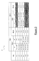
- Figure 3 shows an exemplary state table ST relating to the connection path Con1, under the above exemplary assumptions on the possible link configurations for the links A and B.
- connection path Con1 may operate according to nine possible states S(j, n) that may be grouped according to six possible state capacities SC1, ... SC6.
- Each state capacity SC1, ... SC6 may be achieved by one or two possible states S(j, 1), S(j, 2).
- a state capacity of 2xC Mb/s may be achieved only by a state S(1,1) in which the link A is in operational state ON with 4-QAM modulation and the link B is in operational state OFF.
- the state power consumption is 5.06 W.
- a state capacity of 10xC Mb/s may be achieved only by a state S(5,1), in which the first link A is in operational state ON with 64-QAM modulation and the link B is in operational state ON with 16-QAM modulation.
- a state capacity of 12xC Mb/s may be achieved only by a state S(6,1), in which both links A, B are in operational state ON with 64-QAM modulation.
- the state table ST comprises six rows, one for each possible state capacity. Each row comprises the state power consumption(s) and configuration information relating to the one or two states So, 1), S(j, 2) providing that state capacity organized in a number of columns.
- a first column of the state table ST preferably comprises the state capacities SC1, ... SC6.
- the state capacities SC1, ... SC6 are preferably expressed in C Mb/s, C being the symbol rate of each link A, B of connection path Con 1.
- a second column and a third column comprise the configuration information CI(j, n) associated to a first state S(j, 1) providing each of the state capacities SC1, ... SC6.
- the second column comprises a first portion of the configuration information Cl(j, 1) related to the link A (in particular, operational state and modulation scheme of the link A), while the third column comprises a second portion of the configuration information Cl(j, 1) related to the link B (in particular, operational state and modulation scheme af the link B).
- a fourth column of the state table ST comprises the state power consumption SP(j, 1) associated to the first state S(j, 1) providing the state capacities SC1, ... SC6.
- the state power consumptions SP(j, 1) are preferably expressed in Watts,
- a fifth column and a sixth column comprise configuration information Gl(j, n) associated to a second state S(j, 2) providing each of the state capacities SG1, ... SC6.
- the fifth column comprises a first portion of the configuration information GI(j, 2) related to the link A (in particular, operational state and modulation scheme of the link A), while the sixth column comprises a second portion of the configuration information Gl(j, 2) related to the link B (in particular, operational state and modulation scheme of the link B).
- a seventh column of the state table ST comprises the state power consumption SP(j, 2) associated to the second state S(j, 2) providing the state capacities SC1, ... SC6.
- the state power consumptions SP(j, 2) are preferably expressed in Watts.
- the operator responsible of managing the network may input the state table ST to the control module CM of the link manager LM through the terminal T.
- the state table ST may be at least partially automatically generated by the control module CM.
- the control module CM may retrieve information needed to generate the state table ST from a database accessible by the link manager LM.
- the state table ST is either automatically or manually generated, it is stored in a memory device of the link manager LM or in database accessible by the link manager LM, so that it may be accessed by the control module CM.
- the link manager LM (in particular, the control module CM) preferably uses the state table ST for setting and changing the state of connection path Con1, as it will be described herein after by referring to the flow chart of Figure 4 .
- the operator responsible of managing the network preferably determines an initial capacity Cinit for connection path Con1.
- the initial capacity Cinit may be determined according to different criteria.
- the initial capacity Cinit is determined on the basis of data traffic requests from users of the communication network which are to be routed on connection path Con1.
- the Quality of Service (QoS) associated to the services transported by these data is taken into account.
- the operator preferably provides the value of the initial capacity Cinit to the control module CM (e.g. by using the keyboard of the terminal T).
- the control module CM Upon reception of the value of the initial capacity Cinit (step 400), the control module CM preferably looks through the state table ST and selects an initial state Sinit (step 401).
- the initial state Sinit is preferably selected amongst the states S(j, n) stored in the state table ST as the state which fulfills the following requirements:
- the initial state Sinit is selected amongst the states S(j, n) having the minimum state capacity, amongst the states having a state capacity higher than or equal to the initial capacity Cinit.
- such a selection guarantees that connection path Con1 and nodes N1, N2 operate according to a configuration which matches the propagation conditions over connection path Con1 by consuming the minimum amount of power and network resources.
- the control module CM receives information relating to the current propagation conditions over the links A, B for properly selecting the initial state Sinit. Such information may be provided to the control module CM either by the operator (through the terminal T) or the by nodes N1, N2 (in particular, by their ACM functions).
- the operator may manually select the initial state Sinit for connection path Con1.
- the control module CM may run a graphical user interface displaying the state table ST onto the display of the terminal T. The operator may then look through the state table ST and directly select the initial state Sinit (e.g. by pressing a key onto the keyboard of the terminal T).
- the control module CM preferably reads in the state table ST the configuration information related to that state Sinit and operates the nodes N1, N2 so that they implement the selected initial state Sinit (step 402), namely so that they configure the data transmission over the links A, B of connection path Con1 (in particular, to configure their respective transmitters) according to the configuration information associated to the initial state Sinit.
- the operator determines that an initial capacity Cinit equal to 6xC Mb/s is sufficient to support the data traffic requests and to provide the required QoS.
- the links A, B of connection path Con1 are configured according to the configuration information Cl(3, 1), namely link A is in operational state ON and is configured to implement a 64-QAM modulation, while link B is in operational state OFF.
- state S(3, 1) does not match the propagation conditions (e.g. the weather is bad and a greater noise immunity is required)
- state S(3, 2) may be selected as initial state Sinit, since the modulation schemes of this state (namely, 16-QAM over link A and 4-QAM over link B) are more robust to adverse propagation conditions than the modulation scheme of state S(3, 1) (namely, 64-QAM).
- a state change trigger Tr preferably comprises information indicative of an event occurring in the communication network CN (or which will occur in the communication network CN) and which may require a state change for the connection path Con1.
- a state change trigger Tr may comprise:
- the state change trigger Tr may be input by the operator responsible of managing the network to the link manager LM by means of the terminal T. This is the case, for instance, when the trigger Tr comprises information indicative of an increase or decrease of the amount of data to be routed on connection path Gon1.
- the state change trigger Tr may be automatically generated and input to the link manager LM by the nodes of the communication network CN. This is the case, for instance, when the trigger Tr comprises an alarm relating to one or more links A, B and/or one or more nodes N1, N2 of connection path Con1.
- the state change trigger Tr may be generated by the control module CM itself. For instance, the operator may decide to trigger the changing of the state of connection path Con1 according to the hour of the day.
- the change state trigger Tr may be automatically generated at the control module CM in cooperation with a clock.
- the control module CM may automatically generate a change state trigger Tr when a problem in the power supply to nodes N1, N2 of connection path Con1 arises. Such a problem may imply a partial or total interruption of the power supply, and devices such as extra batteries or photovoltaic panels may be used, which however provide a limited power.
- the change state trigger Tr may be automatically generated at the control module CM when such devices are switched on.
- the control module CM Upon reception of a change state trigger Tr, the control module CM preferably processes the information comprised in the change state trigger Tr (step 404). In particular, at step 404, the control module CM may determine a new capacity Cnew which the connection path Con1 shall support, or a new power consumption Pnew which the connection path Con1 shall consume or new propagation conditions over links A, B of connection path Gon1.
- control module CM preferably checks whether a state change of the connection path Con1 is needed.
- control module CM if at step 404 the control module CM has determined from the state change trigger Tr a new capacity Cnew, at step 405 the control module CM preferably checks whether the state capacity of the initial state Sinit is equal to or higher than the new capacity Cnew and, in the negative, it determines that a state change is needed.
- the control module CM if at step 404 the control module CM has determined from the state change trigger Tr a new power consumption Pnew, at step 405 the control module CM preferably checks whether the state power consumption of the initial state Sinit is lower than or equal to the new power consumption Pnew and, in the negative, it determines that a state change is needed.
- control module CM if at step 404 the control module CM has determined from the state change trigger Tr new propagation conditions over the links A, B, at step 405 the control module preferably checks whether the initial state Sinit matches the new propagation conditions and, in the negative, it determines that a state change is needed.
- step 405 the control module CM determines that a state change of the connection path Con1 is not needed, no action is further taken by the control module CM, which then waits for possible new change state triggers Trs.
- the control module CM looks again through the state table ST and selects, amongst the states S(j, n), a new state Snew matching the new capacity Cnew or the new power consumption Pnew or the new propagation conditions.
- the new state Snew is preferably selected amongst the states S(j, n) as the state which fulfills the following requirements:
- the new state Snew is selected amongst the states S(j, n) having the minimum state capacity, amongst the states having a state capacity higher than or equal to the initial capacity Cinit or new capacity Cnew, if a new capacity Cnew was determined from the trigger Tr.
- a selection guarantees that connection path Con1 and nodes N1, N2 continues operating according to a configuration which matches the propagation conditions over connection path Con1 by consuming the minimum amount of power and network resources.
- control module CM preferably reads in the state table ST the configuration information related to the new state Snew and operates the nodes N1, N2 so that they implement the selected new state Snew, namely so that they configure the data transmission over the links A, B of connection path Con1 (in particular, they configure their respective transmitters) according to the configuration information associated to the new state Snew.
- the nodes N1, N2 preferably change their configuration by using their ACM and ATPC functions.
- Step 404-406 may be manually performed by the operator responsible of managing the network by means of the terminal T, which may display the table ST.
- the control module CM may run the graphical user interface allowing to display the state table ST onto the display of the terminal T.
- the operator decides to change the state of connection path Con1
- it manually selects the new state Snew (e.g. by pressing a key onto the keyboard of the terminal T).
- the control module CM preferably performs step 407 described above.
- the operator may realize that the amount of data to be routed over connection path Gan1 is increasing from the initial capacity Cinit to a new capacity Cnew (e.g. because new users join the communication network) so that the state capacity of the initial state Sinit (for instance, the state S(2, 1) having a state capacity SC2 of 4xC Mb/s) is no more sufficient to support the data transmission.
- the operator may input the new capacity Cnew in the form of a state change trigger Tr to the link manager LM which, upon reception of the trigger Tr, determines that a change of the state of the connection path Con1 from the initial state Sinit to a new state Snew whose state capacity is higher than or equal to Cnew is needed.
- the link manager LM may select the new state Snew between state S(3, 1) and S(3, 2), and in particular it may select as new state Snew the state S(3, 1), whose state capacity SC3 is equal to 6xC Mb/s and is sufficient to support transmission of the increased amount of data, while guaranteeing the minimum power consumption, provided that the propagation conditions over the links A, B are matched.
- one of the nodes N1, N2 may detect a failure affecting one of the links of connection path Con1, e.g. the link B.
- an alarm indicating the failure is received at the link manager LM in the form of a state change trigger Tr.
- the link manager LM may decide to select a new state Snew whereby the link B is in operational state OFF and the state capacity (which basically is the link capacity of the link A) is higher than or equal to the state capacity of the connection path Con1 before the failure of the link B.
- the link manager LM may also decide to apply a traffic prioritization scheme on the basis of the QoS of the services routed over connection path Con1, in order to guarantee transmission of higher priority traffic only.
- the operator may decide to switch from one state to another on the basis of traffic statistics over a period of time, e.g. one day. It is assumed, for example, that such statistics foresee that during the day the traffic requests over connection path Con1 change in such a way that
- the operator may provide the above time schedule to the link manager LM through the terminal T.
- the link manager LM may then implement a clock and, by comparing the clock with the time schedule provided by the operator, generating suitable state change triggers comprising the requested capacities Cnew.
- the link manager LM may set connection path Con1 to operate according to state S(3, 1) during the morning, switch to state S(5, 1) between 12:44 am to 14:40 pm, switch again to state S(3, 1) during the afternoon and finally switch to state S(1, 1) during the evening and night, provided that such states match the propagation conditions over connection path Con1 (which may vary with time during the day).
- the state of the connection path Con1 may be changed based on a variation in the propagation conditions.
- the link manager LM may decide to switch the state of connection path Con1 from an initial state Sinit to a state Snew guaranteeing a more robust data transmission, possibly at the expense of a lower capacity.
- state table ST of Figure 3 if the initial state Sinit is S(2, 1) and the modulation on link A is 16-QAM, when link A experiences bad weather conditions the link manager LM may decide to switch to a state having the same state capacity SC2 but applying a more robust modulation scheme, e.g. 4-QAM (state S(2, 2) of state table ST). If the initial state is S(6, 1) and the modulation on both links A, B is 64-QAM, when connection path Con1 experiences bad weather conditions the link manager LM may decide to switch to a state applying a more robust modulation scheme, e.g. state S(4, 1) wherein the modulation is 16-QAM, at the expense of a lower capacity.
- a more robust modulation scheme e.g. state S(4, 1) wherein the modulation is 16-QAM
- the state of connection path Con1 may be changed according to power consumption requirements. For instance, over a connection path Con1 operating according to e.g. state S(4, 1) of state table ST, a need to reduce the power consumption of any of the nodes N1, N2 may arise when a failure occurs in a node apparatus or the battery level of a node apparatus drops below a minimum level. In such situations, it is required that the power consumption of the node decreases for guaranteeing its operation. In this case, the link manager LM may decide to switch from state S(4, 1) to a state requiring a lower level of power, e.g. state S(3, 1), at the expense of a lower capacity.
- the method of the present invention advantageously allows optimising the power consumption of each connection path Con1 of the communication network CN (namely, of the nodes terminating the connection path Con1).
- the method allows changing the state of the connection path Con1 so as to take into account the actual capacity requirements as well as the actual propagation conditions (namely, the actual amount of traffic to be supported by the communication network and the requirements resulting from the presence of possible failures, interferences, alarms as well as bad propagation conditions, etc.), which may be highly variable over time.
- the method described above allows performing the change of the state of the connection path Con1 by consuming the minimum power.
- connection path Con1 of the communication network CN comprising two parallel links, but it may be likewise applied to any connection path of the communication network CN comprising any number of links (even a single link).
- the method for managing the power consumption of the present invention may be applied to the entire communication network CN.
- a state table ST as described above is preferably compiled for each connection path of the communication network CN and stored in a link manager LM.
- the network manager NM shown in Figure 1 preferably cooperates with the link managers LM of the communication network CN and collects the information stored within the state tables ST of the connection paths of the communication network CN.
- the network manager NM After deploying the communication network CN, the network manager NM preferably runs an optimisation algorithm able to find a respective state for each connection path of the communication network CN, so that the communication network CN as a whole consumes the minimum power.
- the respective state for a connection path that the network manager NM may find is not necessarily the state guaranteeing the minimum power consumption for the single connection path. It is indeed the state that, combined with the states of all other connection paths, guarantees the minimum power consumption of the whole communication network CN.
- the network manager NM When one or more of the conditions described above triggering the change of the state of a connection path occur, the network manager NM preferably runs the optimisation algorithm and, as a result, it may find that one or more connection paths of the communication network CN shall change their state. Therefore, the network manager NM preferably communicates the new states to the link managers LM in charge of the connection paths which shall change their state.
- the control module CM of each link manager LM preferably retrieves the configuration information associated to the new state for the respective connection path and operate the nodes terminating that connection so that they implement the selected configuration. The nodes may switch to the selected configuration by using their ACM and ATPG functions.
- the method of the present invention may be executed in a centralized way and it allows optimising the power consumption not only of the single connection paths of the communication network CN but also of the entire communication network CN by taking into account the actual capacity needs of the communication network CN.
- the functions of the various elements shown in Figures 1 and 2 may be provided through the use of dedicated hardware, as well as hardware capable of executing software in association with appropriate software.
- the functions of the various elements may be provided by a single dedicated processor, by a single shared processor or by a plurality of individual processors, some of which may be shared.
- the elements may comprise, without limitation, a digital signal processor (DSP) hardware, a network processor, an application specific integrated circuit (ASIC), a field programmable gate array (FPGA), a read-only memory (ROM) for storing software, a random access memory (RAM) and a non volatile storage.
- DSP digital signal processor
- ASIC application specific integrated circuit
- FPGA field programmable gate array
- ROM read-only memory
- RAM random access memory
- non volatile storage a non volatile storage.
- Other hardware conventional and/or custom, may also be included.
- any block diagrams herein, as those of Figures 1 and 2 represent conceptual views of illustrative circuitry embodying the principles of the invention.
- any flow charts, flow diagrams, state transition diagrams, pseudo code, and the like, as that of Figure 4 represent various processes which may be substantially represented in computer readable medium and so executed by a computer or processor, whether or not such computer or processor is explicitly shown.
Landscapes
- Engineering & Computer Science (AREA)
- Computer Networks & Wireless Communication (AREA)
- Signal Processing (AREA)
- Mobile Radio Communication Systems (AREA)
Abstract
Description
- The present invention generally relates to the field of radio communication networks. In particular, the present invention relates to the management of power consumption in a radio communication network.
- A radio communication network typically comprises a plurality of nodes connected by radio links. Two nodes of the radio communication network exchange information in the form of a data flow (usually in the form of a stream of bits) modulating a radio signal. The number of transmitted bits in the time unit over a radio link is typically referred to as the "data transmission rate" or "data transmission capacity" or simply "capacity" of the radio link. Different modulation and coding schemes are capable of achieving different capacities.
- Typically, the radio signal is affected by the propagation conditions over the radio link. For example, the propagation conditions on the radio link depend on the weather conditions, the presence/absence of interferences, the presence/absence of multi-paths, and so on. Adverse propagation conditions (i.e. bad weather, presence of interferences, presence of multi-paths) may cause the radio signal to attenuate or fade. In this situation the receiver may not correctly retrieve the data flow from the received signal and the bit error rate (BER) of the data flow accordingly increases.
- As known, in order to face attenuation or fading of the radio signal due to adverse propagation conditions, the so-called Adaptive Coding Modulation technique (ACM) can be used. According to the ACM, the modulation and coding of a radio signal are dynamically varied according to the propagation conditions of the radio link used for conveying the radio signal.
- In particular, according to the ACM, the transmitter typically receives from the receiver a control signal indicating the conditions of the radio link, and according to this control signal dynamically modifies the modulation and/or coding of the radio signal.
- When the propagation conditions of the radio link are good (e.g. when the weather conditions are good and interferences are absent), modulation and coding schemes with the highest available data transmission capacity are usually used. Typical examples of such schemes are 16-QAM, 64-QAM, or 256-QAM (Quadrature Amplitude Modulation). Indeed, the higher the number of constellation points or symbols for a given modulation scheme, the higher the number of bits per symbol transported by the signal and hence the higher the data transmission capacity, at the expense of a lower noise immunity. On the contrary, if the propagation conditions of the radio link get worse (e.g. when fog, rain or snow is present on the radio link), one typically uses a modulation and coding scheme with a greater noise immunity and lower capacity, e.g. 4-QAM.
- Recently, the need to design radio communication networks with a controlled and possibly minimized power consumption raised. This need is driven on the one side by the ever more emerging concern about the environmental impact of communication installations and on the other side by the target of reducing costs.
- In the field of radio communication networks, a known technique allowing to reduce the power transmitted by a network node is the so-called Automatic Transmitter Power Control (ATPC). Such technique provides for adjusting the output power at the transmitting end of a radio link by monitoring the power of the signal detected at the receiving end of the link.
- According to the ATPG technique, when the signal propagates on the radio link in good conditions, e.g. good weather, the output power of the transmitter is maintained at a value which is typically lower that its maximum value. When attenuation or fading arises and the received signal drops below a certain threshold thus leading to errors in the communication, the ATPC provides for increasing the output power of the transmitter up to a maximum value, so as to ensure that the received signal is above the threshold which guarantees an acceptable bit error rate.
- In a radio communication network implementing the ACM technique, when the propagation conditions are good, modulation and coding schemes achieving the highest capacity (i.e. the modulation schemes comprising the highest number of constellation points) are usually used and the full available capacity of the radio links is exploited. The power consumption of the network is directly related to the modulation scheme used, namely it increases as the number of constellation points increases. Accordingly, in good propagation conditions, the maximum power consumption is reached.
- However, in most situations, this may result in over-provisioning the capacity of the radio links as compared with the actual amount of data exchanged between the nodes of the radio network. Therefore, disadvantageously, both the capacity of the links and the power may be unnecessarily wasted.
- Even if the ATPC technique is implemented within the radio communication network in conjunction with the ACM technique, the reduction/increase of the transmitter's power according to ATPC is triggered only by the level of the signal detected at the receiver, and accordingly the actual amount of data to be transmitted over the radio link is not taken into account. Disadvantageously, this may lead to a not efficient exploitation of the capacity of the links and to a not optimized power consumption.
- Accordingly, the inventors have addressed the problem of providing a method for managing the power consumption in a radio communication network, which allows optimising the power consumption and, at the same time, efficiently exploiting the capacity of the network radio links.
- According to a first aspect, embodiments of the present invention provide a method for managing a power consumption of a radio communication network, the radio communication network comprising at least two nodes and a connection path for connecting the at least two nodes under propagation conditions of the connection path, the method comprising:
- a) determining a set of states of the connection path, wherein the connection path, in each state, has a state capacity and a state power consumption;
- b) upon reception of a request relating to traffic carried on the connection path, selecting a state having a minimum state power consumption within the set of states, the selected state having a state capacity higher than or equal to a capacity associated to the traffic and matching the propagation conditions of the connection path; and
- c) operating the nodes so as to bring the connection path in the selected state.
- In the following description and in the claims, the expression "propagation conditions" will indicate the conditions under which propagation of a radio signal takes place over a radio link. The propagation conditions comprise one or more of: the weather conditions over the radio link, the presence/absence of interferences, the presence/absence of multi-paths, and so on.
- Moreover, the expression "a state matching the propagation conditions of the connection path" is understood as meaning that, when the connection path is brought to (namely, is operated in accordance with) such state, each radio link of the connection path has a given configuration, namely a given operational state (ON/OFF), a given modulation scheme, a given coding scheme and so on, in such a way so as to guarantee a reliable data transmission over the connection path under that propagation conditions.
- Preferably, the selected state has a minimum state capacity amongst the states having a state capacity higher than or equal to the capacity associated to the traffic.
- Preferably, each state of the set of states of the connection path is indicative of a possible configuration of one or more links comprised in the connection path, the possible configuration comprising, for each of the one or more links, one or more of:
- an operational state ON-OFF of the link;
- a modulation scheme applied for data transmission over the link;
- a coding scheme applied for data transmission over the link;
- a symbol rate applied for data transmission over the link; and
- a number of independent radio frequency carriers and frequencies of the radio frequency carriers used for data transmission over the link.
- Preferably, the request is indicative of a variation in the capacity associated to said traffic.
- Preferably, the request is indicative of a variation in the propagation conditions.
- Preferably, the request is indicative of a variation in the power consumption of the connection path.
- Preferably, the request is indicative of a failure affecting the connection path.
- Preferably, the operating is performed by using at least one adaptive code modulation function and/or at least one automatic transmitter power control function of the nodes.
- According to a second aspect, embodiments of the present invention provide a computer program product comprising computer-executable instructions for performing, when the program is run on a computer, the steps of the method as set forth above.
- According to a third aspect, embodiments of the present invention provide a link manager for a radio communication network comprising at least two nodes and a connection path for connecting the at least two nodes under propagation conditions of the connection path, the link manager being configured to:
- determine a set of states of said connection path, wherein the connection path, in each state, has a state capacity and a state power consumption;
- upon reception of a request relating to traffic carried on the connection path, select a state having a minimum state power consumption within the set of states, the selected state having a state capacity higher than or equal to a capacity associated to the traffic and matching the propagation conditions of the connection path; and
- operate the nodes so as to bring the connection path in the selected state.
- Preferably, the link manager is implemented at a node of the radio communication network.
- Alternatively, the link manager is implemented at an apparatus connected to a node of the radio communication network.
- According to a fourth aspect, the present invention provides a radio communication network comprising at least two nodes and a connection path for connecting the at least two nodes under propagation conditions of the connection path, the radio communication network further comprising a link manager as set forth above.
- Preferably, the communication network further comprises a network manager configured to:
- upon reception of the request, select a state within the set of states, the selected state having a state capacity higher than or equal to a capacity associated to the traffic and the matching propagation conditions of the connection path, the selected state being such that the communication network as a whole consumes a minimum power; and
- operate the nodes so as to bring the connection path in the selected state.
- Embodiments of the invention will be better understood by reading the following detailed description, given by way of example and not of limitation, to be read with reference to the accompanying drawings, wherein:
-
Figure 1 shows an exemplary communication network; -
Figure 2 shows in further detail a portion of the communication network ofFigure 1 , according to an embodiment of the present invention; -
Figure 3 shows a state table relating to the connection path comprised in the network portion shown inFigure 1 ; and -
Figure 4 is a flow chart illustrating the operation for setting and changing the state of the connection path comprised in the network portion shown inFigure 1 . -
Figure 1 schematically shows a radio communication network CN (in the following description referred to also as "communication network CN") suitable for implementing the method according to a preferred embodiment of the present invention. - The radio communication network CN comprises a number of network nodes. The network nodes are interconnected by means of connection paths, each connection path comprising either a single radio link or a number of parallel radio links (in the following referred to as "links"). Each link of a connection path is terminated at its opposite ends by a transmitter and a receiver (or by two transceivers, if the link is bidirectional). In
Figure 1 , for sake of simplicity, five nodes N1, ... N5 are shown and five connection paths Gon1, ... Con5 connecting them according to a partially meshed topology. In particular, nodes N1 and N2 are interconnected by means of a connection path Con1. - The nodes of the communication network CN may be configured to implement the Adaptive Coding Modulation (ACM) technique. Preferably, the nodes of the communication network CN are configured to implement the ACM technique in conjunction with the Automatic Transmitter Power Control (ATPC) technique.
- Further, the communication network CN may optionally comprise one or more link managers and a network manager NM cooperating with the nodes of the communication network CN.
- Each link manager is configured to perform management functions upon the link(s) of a connection path of the communication network CN. To this purpose, the link manager is configured to cooperate with the nodes of the communication network CN connected by that connection path.
Figure 1 shows, by way of non limiting example, only one link manger LM configured to perform management functions upon connection path Con1 and therefore to cooperate with node N1 and node N2. The link manager LM may be implemented as a stand-alone apparatus connected to any one of the nodes N1, N2. InFigure 1 , by way of example, the link manager LM is connected to node N1. Alternatively, the link manager LM may be integrated within one of nodes N1, N2, for instance node N1. Alternatively, the function of the link manager LM may be distributed at both the nodes N1, N2. - The network manager NM is adapted to perform management functions upon the links of all the connection paths Con1, ... Con5 of the communication network CN. The network manager NM is therefore configured to cooperate with all the nodes N1,... N5 of the communication network CN and with all the link managers of the communication network CN. The network manager NM may be implemented as a stand-alone apparatus connected either to any one of the nodes N1,... N5 or to any one of the link managers. In
Figure 1 , by way of non limiting example, the network manager NM is connected to the link manager LM of the connection path Gon1. - In operative conditions, the communication network CN connects a plurality of users which exchange data through the nodes N1,... N5 of the network CN. The data are carried over the connection paths Con1, ... Con5, each connection path Con1, ... Con5 operating at a respective capacity (i.e. a respective data transmission rate). The data exchanged between the network nodes N1,... N5 may carry different services, each of them being associated to a respective Quality of Service (QoS).
-
Figure 2 shows a portion of the communication network CN, comprising the nodes N1, N2, the connection path Con1 and the link manager LM. By way of non limiting example, theconnection path Con 1 comprises two links A, B. Both the links A, B may be full-duplex links allowing a bidirectional exchange of information between nodes N1, N2. It is assumed that both the links A, B are able to support the transmission of digitally modulated data at a symbol rate equal to C symbol/s. The symbol rate represents the number of transmitted symbols per second, the symbol being an integer number of bits equal to or higher than 1. - As shown in
Figure 2 , a terminal T may be optionally connected to the link manager LM. The terminal T preferably comprises a keyboard and a display. The terminal T allows an operator responsible of managing the network to interact with the link manager LM, as it will be described in further detail herein after. - The link manager LM preferably comprises a control module CM and a state table ST.
- The control module CM is preferably implemented by means of a dedicated hardware component, or by means of a hardware component capable of executing a software, in combination with a dedicated software, or by means of a dedicated software component.
- The state table ST preferably comprises information indicative of a set of possible states in which the connection path Con1 may operate. The state table ST is preferably generated by the control module CM of the link manager LM, as it will be described in detail herein after.
- For generating the state table ST, the operator shall know, for each link A, B of the connection path Con1, the possible link configurations. Each link configuration preferably comprise one or more of the following parameters:
- an operational state of the link, i.e. whether the link is ON (i.e. the link is working) or OFF (i.e. the link is not working);
- the modulation scheme applied for data transmission over the link;
- the coding scheme applied for data transmission over the link;
- the symbol rate applied for data transmission over the link; and
- the number of independent RF carriers and frequency of the RF carriers used to transport the data over the link.
- Moreover the operator shall know, for each possible link configuration, the link capacity and the link power consumption. The link power consumption of a link comprises the power consumed by the radio interfaces terminating that link at the network nodes N1, N2 and the power emitted by the antennas at the nodes N1, N2 for transmitting the radio signals carrying the data over the link.
- For simplicity, it is assumed herein after that the possible link configurations of the links A, B may differ only by operational state (namely, ON or OFF) and modulation scheme of the link. The coding scheme, the number of independent RF carriers, the frequency of the RF carriers, etc. of the links A, B are fixed. Further, it is assumed that the supported modulation schemes, the coding scheme, the number of independent RF carriers, the frequency of the RF carriers, etc. are the same on the links A, B of the connection path Con1. In other words, the links A, B of the connection path Con1 are interchangeable.
- Further, it is assumed that each link A, B in operational state ON may be configured to transmit with a 4-QAM, 16-QAM or 64-QAM modulation scheme. In other words, each link A, B has four possible link configurations:
- first link configuration: operational state OFF;
- second link configuration: operational state ON, 4-QAM;
- third link configuration: operational state ON, 16-QAM; and
- fourth link configuration: operational state ON, 64-QAM.
- This is not limiting, since any modulation scheme may be adopted over the first and second links A, B. Further, it is assumed that the 4-QAM, 16-QAM or 64-QAM modulation schemes allow achieving, on each link, a link capacity of 2xC Mb/s, 4xC Mb/s and 6xC Mb/s with a link power consumption of 5.06 W, 5.38 W and 7.39 W, respectively.
- The operator responsible of managing the network may then provide a plurality of connection configurations or states for the connection path Con1, each state comprising a respective combination of link configurations of the links A, B. For instance:
- first state: link A in operational state ON, 4-QAM and link B in operational state OFF;
- second state: link A in operational state ON, 16-QAM and link B in operational state OFF;
- third state: link A in operational state ON, 64-QAM and link B in operational state OFF;
- fourth state: link A in operational state ON, 4-QAM and link B in operational state ON, 4-QAM;
- fifth state: link A in operational state ON, 16-QAM and link B in operational state ON, 4-QAM;
- fifth state: link A in operational state ON, 64-QAM and link B in operational state ON, 4-QAM; and so on.
- Then, for each state, the operator preferably determines a respective state capacity as a sum of the link capacities of the links A, B. More than one state may achieve the same state capacity, as it will be discussed in further detail herein after. For instance, both the second state (link A in operational state ON, 16-QAM and link B in operational state OFF) and the fourth state (link A in operational state ON, 4-QAM and link B in operational state ON using 4-QAM) achieve a same state capacity equal to 4xC Mb/s.
- Then, the operator preferably determines a state power consumption for each of the above states, as a sum of the link power consumptions of the links A, B.
- Then, the operator may summarize the above states with the respective state capacities and state power consumptions in the state table ST.
- In the state table ST, the states are preferably grouped according to their state capacity. In particular, for each possible state capacity, the state table ST comprises a respective row in turn comprising the state power consumption(s) of the state(s) providing that state capacity and configuration information relating to that state(s).
-
Figure 3 shows an exemplary state table ST relating to the connection path Con1, under the above exemplary assumptions on the possible link configurations for the links A and B. - According to such exemplary assumptions, the connection path Con1 may operate according to nine possible states S(j, n) that may be grouped according to six possible state capacities SC1, ... SC6. Each state capacity SC1, ... SC6 may be achieved by one or two possible states S(j, 1), S(j, 2).
- In particular, a state capacity of 2xC Mb/s may be achieved only by a state S(1,1) in which the link A is in operational state ON with 4-QAM modulation and the link B is in operational state OFF. In this case, the state power consumption is 5.06 W.
- Further, a state capacity of 4xC Mb/s may be achieved by two states S(2,1), S(2,2): in S(2,1) the link A is in operational state ON with 16-QAM modulation and the link B is in operational state OFF, the state power consumption being 5.38 Watt; in S(2,2) both links A, B are in operational state ON with 4-QAM modulation, the state power consumption being 5.06x2=10.12 W.
- Further, a state capacity of 6xC Mb/s may be achieved by two states S(3,1), S(3,2): in S(3,1) the link A is in operational state ON with 64-QAM modulation and the link B is in operational state OFF, the state power consumption being 7.39 W; in S(3,2) the link A is in operational state ON with 16-QAM modulation and the link B is in operational state ON with 4-QAM modulation, the state power consumption being 5.38+5.06=10.44 W.
- Further, a state capacity of 8xC Mb/s may be achieved by two states S(4,1), S(4,2): in S(4,1) both links A, B are in operational state ON with 16-QAM modulation, the state power consumption being 5.38x2=10.76 W; in S(4,2) the link A is in operational state ON with 64-QAM modulation and the link B is in operational state ON with 4-QAM modulation, the state power consumption being 7.39+5.06=12.45 W.
- Further, a state capacity of 10xC Mb/s may be achieved only by a state S(5,1), in which the first link A is in operational state ON with 64-QAM modulation and the link B is in operational state ON with 16-QAM modulation. In this case, the state power consumption is 7.39+5.38=12.77 W.
- Finally, a state capacity of 12xC Mb/s may be achieved only by a state S(6,1), in which both links A, B are in operational state ON with 64-QAM modulation. In this case, the state power consumption is 7.39x2=14.78 W.
- As shown in
Figure 3 , the state table ST comprises six rows, one for each possible state capacity. Each row comprises the state power consumption(s) and configuration information relating to the one or two states So, 1), S(j, 2) providing that state capacity organized in a number of columns. - A first column of the state table ST preferably comprises the state capacities SC1, ... SC6. The state capacities SC1, ... SC6 are preferably expressed in C Mb/s, C being the symbol rate of each link A, B of
connection path Con 1. - A second column and a third column comprise the configuration information CI(j, n) associated to a first state S(j, 1) providing each of the state capacities SC1, ... SC6. In particular, the second column comprises a first portion of the configuration information Cl(j, 1) related to the link A (in particular, operational state and modulation scheme of the link A), while the third column comprises a second portion of the configuration information Cl(j, 1) related to the link B (in particular, operational state and modulation scheme af the link B).
- A fourth column of the state table ST comprises the state power consumption SP(j, 1) associated to the first state S(j, 1) providing the state capacities SC1, ... SC6. The state power consumptions SP(j, 1) are preferably expressed in Watts,
- A fifth column and a sixth column comprise configuration information Gl(j, n) associated to a second state S(j, 2) providing each of the state capacities SG1, ... SC6. In particular, the fifth column comprises a first portion of the configuration information GI(j, 2) related to the link A (in particular, operational state and modulation scheme of the link A), while the sixth column comprises a second portion of the configuration information Gl(j, 2) related to the link B (in particular, operational state and modulation scheme of the link B).
- A seventh column of the state table ST comprises the state power consumption SP(j, 2) associated to the second state S(j, 2) providing the state capacities SC1, ... SC6. The state power consumptions SP(j, 2) are preferably expressed in Watts.
- After generating the state table ST, the operator responsible of managing the network may input the state table ST to the control module CM of the link manager LM through the terminal T.
- Alternatively to the above described manual generation of the state table ST, the state table ST may be at least partially automatically generated by the control module CM. In this case, the control module CM may retrieve information needed to generate the state table ST from a database accessible by the link manager LM.
- Once the state table ST is either automatically or manually generated, it is stored in a memory device of the link manager LM or in database accessible by the link manager LM, so that it may be accessed by the control module CM.
- The link manager LM (in particular, the control module CM) preferably uses the state table ST for setting and changing the state of connection path Con1, as it will be described herein after by referring to the flow chart of
Figure 4 . - In operative conditions, after deploying the connection path Con1 between nodes N1, N2, the operator responsible of managing the network preferably determines an initial capacity Cinit for connection path Con1. The initial capacity Cinit may be determined according to different criteria. Preferably, the initial capacity Cinit is determined on the basis of data traffic requests from users of the communication network which are to be routed on connection path Con1. Optionally, the Quality of Service (QoS) associated to the services transported by these data is taken into account.
- Then, the operator preferably provides the value of the initial capacity Cinit to the control module CM (e.g. by using the keyboard of the terminal T).
- Upon reception of the value of the initial capacity Cinit (step 400), the control module CM preferably looks through the state table ST and selects an initial state Sinit (step 401). The initial state Sinit is preferably selected amongst the states S(j, n) stored in the state table ST as the state which fulfills the following requirements:
- its associated state capacity is higher than or equal to the initial capacity Cinit;
- it matches the current propagation conditions over the links A, B of connection path Con1 (i.e. it guarantees a reliable data transmission over the links A, B, given their current propagation conditions); and
- it is associated to the minimum state power consumption.
- Preferably, the initial state Sinit is selected amongst the states S(j, n) having the minimum state capacity, amongst the states having a state capacity higher than or equal to the initial capacity Cinit. Advantageously, such a selection guarantees that connection path Con1 and nodes N1, N2 operate according to a configuration which matches the propagation conditions over connection path Con1 by consuming the minimum amount of power and network resources.
- At
step 401, the control module CM receives information relating to the current propagation conditions over the links A, B for properly selecting the initial state Sinit. Such information may be provided to the control module CM either by the operator (through the terminal T) or the by nodes N1, N2 (in particular, by their ACM functions). - Alternatively to the above described automatic selection of the initial state Sinit performed by the control module CM, the operator may manually select the initial state Sinit for connection path Con1. In this case, the control module CM may run a graphical user interface displaying the state table ST onto the display of the terminal T. The operator may then look through the state table ST and directly select the initial state Sinit (e.g. by pressing a key onto the keyboard of the terminal T).
- Once the initial state Sinit is selected either automatically or manually, the control module CM preferably reads in the state table ST the configuration information related to that state Sinit and operates the nodes N1, N2 so that they implement the selected initial state Sinit (step 402), namely so that they configure the data transmission over the links A, B of connection path Con1 (in particular, to configure their respective transmitters) according to the configuration information associated to the initial state Sinit.
- For instance, with reference to the exemplary state table ST of
Figure 3 , it is assumed that the operator determines that an initial capacity Cinit equal to 6xC Mb/s is sufficient to support the data traffic requests and to provide the required QoS. The initial state Sinit is then preferably selected among the states S(3, 1) and S(3, 2) having the state capacity 6xC Mb/s. If both states S(3, 1) and S(3, 2) match the propagation conditions over connection path Con1 (e.g. the weather is good), state S(3, 1) of table ST ofFigure 3 may be selected as initial state Sinit, since it has the minimum state power consumption SP(3, 1)= 7.39 W. In this case, the links A, B of connection path Con1 are configured according to the configuration information Cl(3, 1), namely link A is in operational state ON and is configured to implement a 64-QAM modulation, while link B is in operational state OFF. If state S(3, 1) does not match the propagation conditions (e.g. the weather is bad and a greater noise immunity is required), state S(3, 2) may be selected as initial state Sinit, since the modulation schemes of this state (namely, 16-QAM over link A and 4-QAM over link B) are more robust to adverse propagation conditions than the modulation scheme of state S(3, 1) (namely, 64-QAM). - Then, the control module CM listens for possible state change triggers Tr (step 403). A state change trigger Tr preferably comprises information indicative of an event occurring in the communication network CN (or which will occur in the communication network CN) and which may require a state change for the connection path Con1. A state change trigger Tr may comprise:
- information indicative of an increase or decrease of the amount of data to be routed on connection path Con1 and/or a change of the Quality of Service (QoS) associated to such data;
- information indicative of a change of propagation conditions over the links A, B of connection path Gon1;
- information indicative of a change of power consumption requirements;
- information indicative of failure involving one or more links A, B of connection path Con1 and/or nodes N1, N2;
- an alarm relating to one or more links A, B of connection path Con1 and/or nodes N1, N2; and
- traffic statistics over periods of time (day, month, year).
- The state change trigger Tr may be input by the operator responsible of managing the network to the link manager LM by means of the terminal T. This is the case, for instance, when the trigger Tr comprises information indicative of an increase or decrease of the amount of data to be routed on connection path Gon1.
- Alternatively, the state change trigger Tr may be automatically generated and input to the link manager LM by the nodes of the communication network CN. This is the case, for instance, when the trigger Tr comprises an alarm relating to one or more links A, B and/or one or more nodes N1, N2 of connection path Con1.
- Alternatively, the state change trigger Tr may be generated by the control module CM itself. For instance, the operator may decide to trigger the changing of the state of connection path Con1 according to the hour of the day. In this case, the change state trigger Tr may be automatically generated at the control module CM in cooperation with a clock. Moreover, the control module CM may automatically generate a change state trigger Tr when a problem in the power supply to nodes N1, N2 of connection path Con1 arises. Such a problem may imply a partial or total interruption of the power supply, and devices such as extra batteries or photovoltaic panels may be used, which however provide a limited power. In this case, the change state trigger Tr may be automatically generated at the control module CM when such devices are switched on.
- Upon reception of a change state trigger Tr, the control module CM preferably processes the information comprised in the change state trigger Tr (step 404). In particular, at
step 404, the control module CM may determine a new capacity Cnew which the connection path Con1 shall support, or a new power consumption Pnew which the connection path Con1 shall consume or new propagation conditions over links A, B of connection path Gon1. - Then, at
step 405, the control module CM preferably checks whether a state change of the connection path Con1 is needed. - In particular, if at
step 404 the control module CM has determined from the state change trigger Tr a new capacity Cnew, atstep 405 the control module CM preferably checks whether the state capacity of the initial state Sinit is equal to or higher than the new capacity Cnew and, in the negative, it determines that a state change is needed. - On the other hand, if at
step 404 the control module CM has determined from the state change trigger Tr a new power consumption Pnew, atstep 405 the control module CM preferably checks whether the state power consumption of the initial state Sinit is lower than or equal to the new power consumption Pnew and, in the negative, it determines that a state change is needed. - Moreover, if at
step 404 the control module CM has determined from the state change trigger Tr new propagation conditions over the links A, B, atstep 405 the control module preferably checks whether the initial state Sinit matches the new propagation conditions and, in the negative, it determines that a state change is needed. - If at
step 405 the control module CM determines that a state change of the connection path Con1 is not needed, no action is further taken by the control module CM, which then waits for possible new change state triggers Trs. - Otherwise, at
step 406, the control module CM looks again through the state table ST and selects, amongst the states S(j, n), a new state Snew matching the new capacity Cnew or the new power consumption Pnew or the new propagation conditions. The new state Snew is preferably selected amongst the states S(j, n) as the state which fulfills the following requirements: - its associated state capacity is higher than or equal to the initial capacity Cinit or the new capacity Cnew, if a new capacity Cnew was determined from the trigger Tr;
- it matches the current propagation conditions over the links A, B of connection path Con1 or the new propagation conditions, if new propagation conditions were determined from the trigger Tr; and
- it is associated to the minimum state power consumption, the minimum state power consumption being equal to or lower than the new power consumption Pnew, if a new power was determined from the trigger Tr.
- Preferably, the new state Snew is selected amongst the states S(j, n) having the minimum state capacity, amongst the states having a state capacity higher than or equal to the initial capacity Cinit or new capacity Cnew, if a new capacity Cnew was determined from the trigger Tr. Advantageously, such a selection guarantees that connection path Con1 and nodes N1, N2 continues operating according to a configuration which matches the propagation conditions over connection path Con1 by consuming the minimum amount of power and network resources.
- Then, at
step 407, the control module CM preferably reads in the state table ST the configuration information related to the new state Snew and operates the nodes N1, N2 so that they implement the selected new state Snew, namely so that they configure the data transmission over the links A, B of connection path Con1 (in particular, they configure their respective transmitters) according to the configuration information associated to the new state Snew. - The nodes N1, N2 preferably change their configuration by using their ACM and ATPC functions.
- Step 404-406 may be manually performed by the operator responsible of managing the network by means of the terminal T, which may display the table ST. In particular, the control module CM may run the graphical user interface allowing to display the state table ST onto the display of the terminal T. When the operator decides to change the state of connection path Con1, it manually selects the new state Snew (e.g. by pressing a key onto the keyboard of the terminal T). Then, the control module CM preferably performs
step 407 described above. - Herein after, some exemplary applications of the above described method are provided.
- According to a first exemplary application, the operator may realize that the amount of data to be routed over connection path Gan1 is increasing from the initial capacity Cinit to a new capacity Cnew (e.g. because new users join the communication network) so that the state capacity of the initial state Sinit (for instance, the state S(2, 1) having a state capacity SC2 of 4xC Mb/s) is no more sufficient to support the data transmission. The operator may input the new capacity Cnew in the form of a state change trigger Tr to the link manager LM which, upon reception of the trigger Tr, determines that a change of the state of the connection path Con1 from the initial state Sinit to a new state Snew whose state capacity is higher than or equal to Cnew is needed. For instance, if the new capacity Cnew is of 5.5xC Mb/s, the link manager LM may select the new state Snew between state S(3, 1) and S(3, 2), and in particular it may select as new state Snew the state S(3, 1), whose state capacity SC3 is equal to 6xC Mb/s and is sufficient to support transmission of the increased amount of data, while guaranteeing the minimum power consumption, provided that the propagation conditions over the links A, B are matched.
- According to a second exemplary application, one of the nodes N1, N2 may detect a failure affecting one of the links of connection path Con1, e.g. the link B. In this case, an alarm indicating the failure is received at the link manager LM in the form of a state change trigger Tr. Upon reception of the trigger Tr, the link manager LM may decide to select a new state Snew whereby the link B is in operational state OFF and the state capacity (which basically is the link capacity of the link A) is higher than or equal to the state capacity of the connection path Con1 before the failure of the link B. The link manager LM may also decide to apply a traffic prioritization scheme on the basis of the QoS of the services routed over connection path Con1, in order to guarantee transmission of higher priority traffic only.
- According to a third exemplary application, the operator may decide to switch from one state to another on the basis of traffic statistics over a period of time, e.g. one day. It is assumed, for example, that such statistics foresee that during the day the traffic requests over connection path Con1 change in such a way that
- during the morning, a capacity equal to 6xC Mb/s is needed;
- the capacity needs rise to 10xC Mb/s at lunch time (namely between 12:44 am to 14:00 pm);
- during the afternoon, a capacity equal to 6xC Mb/s is needed; and
- the capacity needs drop to 2xC Mb/s during the evening and night.
- In this case, the operator may provide the above time schedule to the link manager LM through the terminal T. The link manager LM may then implement a clock and, by comparing the clock with the time schedule provided by the operator, generating suitable state change triggers comprising the requested capacities Cnew. In particular, the link manager LM may set connection path Con1 to operate according to state S(3, 1) during the morning, switch to state S(5, 1) between 12:44 am to 14:40 pm, switch again to state S(3, 1) during the afternoon and finally switch to state S(1, 1) during the evening and night, provided that such states match the propagation conditions over connection path Con1 (which may vary with time during the day).
- According to a fourth exemplary application, the state of the connection path Con1 may be changed based on a variation in the propagation conditions. In this situation, when any of the nodes N1, N2 detects a variation in propagation conditions determining a degradation of the data transmission over the connection path Con1, the link manager LM may decide to switch the state of connection path Con1 from an initial state Sinit to a state Snew guaranteeing a more robust data transmission, possibly at the expense of a lower capacity. In the example of state table ST of
Figure 3 , if the initial state Sinit is S(2, 1) and the modulation on link A is 16-QAM, when link A experiences bad weather conditions the link manager LM may decide to switch to a state having the same state capacity SC2 but applying a more robust modulation scheme, e.g. 4-QAM (state S(2, 2) of state table ST). If the initial state is S(6, 1) and the modulation on both links A, B is 64-QAM, when connection path Con1 experiences bad weather conditions the link manager LM may decide to switch to a state applying a more robust modulation scheme, e.g. state S(4, 1) wherein the modulation is 16-QAM, at the expense of a lower capacity. - According to a fifth exemplary application, the state of connection path Con1 may be changed according to power consumption requirements. For instance, over a connection path Con1 operating according to e.g. state S(4, 1) of state table ST, a need to reduce the power consumption of any of the nodes N1, N2 may arise when a failure occurs in a node apparatus or the battery level of a node apparatus drops below a minimum level. In such situations, it is required that the power consumption of the node decreases for guaranteeing its operation. In this case, the link manager LM may decide to switch from state S(4, 1) to a state requiring a lower level of power, e.g. state S(3, 1), at the expense of a lower capacity.
- The method of the present invention advantageously allows optimising the power consumption of each connection path Con1 of the communication network CN (namely, of the nodes terminating the connection path Con1). Indeed, the method allows changing the state of the connection path Con1 so as to take into account the actual capacity requirements as well as the actual propagation conditions (namely, the actual amount of traffic to be supported by the communication network and the requirements resulting from the presence of possible failures, interferences, alarms as well as bad propagation conditions, etc.), which may be highly variable over time. In the meanwhile, the method described above allows performing the change of the state of the connection path Con1 by consuming the minimum power.
- The method for managing the power consumption has been described above with reference to a connection path Con1 of the communication network CN comprising two parallel links, but it may be likewise applied to any connection path of the communication network CN comprising any number of links (even a single link).
- The method for managing the power consumption of the present invention may be applied to the entire communication network CN. In this case, a state table ST as described above is preferably compiled for each connection path of the communication network CN and stored in a link manager LM. The network manager NM shown in
Figure 1 preferably cooperates with the link managers LM of the communication network CN and collects the information stored within the state tables ST of the connection paths of the communication network CN. - After deploying the communication network CN, the network manager NM preferably runs an optimisation algorithm able to find a respective state for each connection path of the communication network CN, so that the communication network CN as a whole consumes the minimum power. In this scenario, the respective state for a connection path that the network manager NM may find is not necessarily the state guaranteeing the minimum power consumption for the single connection path. It is indeed the state that, combined with the states of all other connection paths, guarantees the minimum power consumption of the whole communication network CN.
- When one or more of the conditions described above triggering the change of the state of a connection path occur, the network manager NM preferably runs the optimisation algorithm and, as a result, it may find that one or more connection paths of the communication network CN shall change their state. Therefore, the network manager NM preferably communicates the new states to the link managers LM in charge of the connection paths which shall change their state. In particular, the control module CM of each link manager LM preferably retrieves the configuration information associated to the new state for the respective connection path and operate the nodes terminating that connection so that they implement the selected configuration. The nodes may switch to the selected configuration by using their ACM and ATPG functions.
- Advantageously, the method of the present invention may be executed in a centralized way and it allows optimising the power consumption not only of the single connection paths of the communication network CN but also of the entire communication network CN by taking into account the actual capacity needs of the communication network CN.
- The functions of the various elements shown in
Figures 1 and2 may be provided through the use of dedicated hardware, as well as hardware capable of executing software in association with appropriate software. The functions of the various elements may be provided by a single dedicated processor, by a single shared processor or by a plurality of individual processors, some of which may be shared. Moreover, the elements may comprise, without limitation, a digital signal processor (DSP) hardware, a network processor, an application specific integrated circuit (ASIC), a field programmable gate array (FPGA), a read-only memory (ROM) for storing software, a random access memory (RAM) and a non volatile storage. Other hardware, conventional and/or custom, may also be included. - It should be appreciated by those skilled in the art that any block diagrams herein, as those of
Figures 1 and2 , represent conceptual views of illustrative circuitry embodying the principles of the invention. Similarly, it will be appreciated that any flow charts, flow diagrams, state transition diagrams, pseudo code, and the like, as that ofFigure 4 , represent various processes which may be substantially represented in computer readable medium and so executed by a computer or processor, whether or not such computer or processor is explicitly shown.
Claims (14)
- A method for managing a power consumption of a radio communication network (CN), said radio communication network (CN) comprising at least two nodes (N1, N2) and a connection path (Con1 connecting said at least two nodes (N1, N2) under propagation conditions of said connection path (Con1), said method comprising:a) determining a set of states (S(j, n)) of said connection path (Con1), wherein said connection path (Con1), in each state, has a state capacity (SCj) and a state power consumption (SP(j, n));b) upon reception of a request (Cinit, Cnew, Pnew) relating to traffic carried on said connection path (Con1), selecting a state (Sinit, Snew) having a minimum state power consumption within said set of states (S1, ... S6), said selected state (Sinit, Snew) having a state capacity (SCj) higher than or equal to a capacity (Cinit, Cnew) associated to said traffic and matching said propagation conditions of said connection path (Con1); andc) operating said nodes (N1, N2) so as to bring said connection path (Con1) in said selected state (Sinit, Snew).
- The method according to claim 1, wherein said selected state (Sinit, Snew) has a minimum state capacity amongst the states (S1, ... S6) having a state capacity (SCj) higher than or equal to said capacity (Cinit, Cnew).
- The method according to claim 1 or 2, wherein each state of said set of states (S1, ... S6) of said connection path (Con1) is indicative of a possible configuration of one or more links (A, B) comprised in said connection path (Con1), said possible configuration comprising, for each of said one or more links (A, B), one or more of:- an operational state ON-OFF of the link (A, B);- a modulation scheme applied for data transmission over the link (A, B);- a coding scheme applied for data transmission over the link (A, B);- a symbol rate applied for data transmission over the link (A, B); and- a number of independent radio frequency carriers and frequencies of the radio frequency carriers used for data transmission over the link (A, B).
- The method according to any of the preceding claims, wherein said request (Cnew) is indicative of a variation in said capacity (Cinit, Cnew) associated to said traffic.
- The method according to any of the preceding claims, wherein said request is indicative of a variation in said propagation conditions.
- The method according to any of the preceding claims, wherein said request (Pnew) is indicative of a variation in the power consumption of said connection path (Con1).
- The method according to any of the preceding claims, wherein said request is indicative of a failure affecting said connection path (Con1).
- The method according to any of the preceding claims, wherein said operating is performed by using at least one adaptive code modulation function and/or at least one automatic transmitter power control function of said nodes (N1, N2).
- A computer program product comprising computer-executable instructions for performing, when the program is run on a computer, the steps of the method according to any of the preceding claims.
- A link manager (LM) for a radio communication network (CN) comprising at least two nodes (N1, N2) and a connection path (Con1) for connecting said at least two nodes (N1, N2) under propagation conditions of said connection path (Con1), said link manager (LM) being configured to:- determine a set of states (S(j, n)) of said connection path (Con1), wherein said connection path (Con1), in each state, has a state capacity (SCj) and a state power consumption (SP(j, n));- upon reception of a request (Cinit, Cnew, Pnew) relating to traffic carried on said connection path (Con1), select a state (Sinit, Snew) having a minimum state power consumption within said set of states (S1, ... S6), said selected state (Sinit, Snew) having a state capacity (SCj) higher than or equal to a capacity (Cinit, Cnew) associated to said traffic and matching said propagation conditions of said connection path (Con1); and- operate said nodes (N1, N2) so as to bring said connection path (Con1) in said selected state (Sinit, Snew).
- The link manager (LM) of claim 10, said link manager (LM) being implemented at a node of said radio communication network (CN).
- The link manager (LM) of claim 10, said link manager (LM) being implemented at an apparatus connected to a node of said radio communication network (CN).
- A radio communication network (CN) comprising at least two nodes (N1, N2) and a connection path (Con1) for connecting said at least two nodes (N1, N2) under propagation conditions of said connection path (Con1), said radio communication network (CN) further comprising a link manager (LM) according to any of claims 10 to 12.
- The communication network (CN) according to claim 13, said communication network (CN) further comprising a network manager (NM) configured to:- upon reception of said request (Cinit, Cnew, Pnew), select a state (Sinit, Snew) within said set of states (S1, ... S6), said selected state (Sinit, Snew) having a state capacity (SCj) higher than or equal to a capacity (Cinit, Cnew) associated to said traffic and matching the propagation conditions of said connection path (Con1), said selected state (Sinit, Snew) being such that said communication network (CN) as a whole consumes a minimum power; and- operate said nodes (N1, N2) so as to bring said connection path (Con1) in said selected state (Sinit, Snew).
Priority Applications (3)
| Application Number | Priority Date | Filing Date | Title |
|---|---|---|---|
| ES11305992T ES2700737T3 (en) | 2011-07-29 | 2011-07-29 | Management of power consumption in a radio communication network |
| EP11305992.7A EP2552051B1 (en) | 2011-07-29 | 2011-07-29 | Management of power consumption in a radio communication network |
| PL11305992T PL2552051T3 (en) | 2011-07-29 | 2011-07-29 | Management of power consumption in a radio communication network |
Applications Claiming Priority (1)
| Application Number | Priority Date | Filing Date | Title |
|---|---|---|---|
| EP11305992.7A EP2552051B1 (en) | 2011-07-29 | 2011-07-29 | Management of power consumption in a radio communication network |
Publications (2)
| Publication Number | Publication Date |
|---|---|
| EP2552051A1 true EP2552051A1 (en) | 2013-01-30 |
| EP2552051B1 EP2552051B1 (en) | 2018-09-05 |
Family
ID=44651550
Family Applications (1)
| Application Number | Title | Priority Date | Filing Date |
|---|---|---|---|
| EP11305992.7A Not-in-force EP2552051B1 (en) | 2011-07-29 | 2011-07-29 | Management of power consumption in a radio communication network |
Country Status (3)
| Country | Link |
|---|---|
| EP (1) | EP2552051B1 (en) |
| ES (1) | ES2700737T3 (en) |
| PL (1) | PL2552051T3 (en) |
Citations (6)
| Publication number | Priority date | Publication date | Assignee | Title |
|---|---|---|---|---|
| EP1357681A1 (en) * | 2002-04-25 | 2003-10-29 | Samsung Electronics Co., Ltd. | Power controllable wireless mobile communications system of adaptive modulation and coding scheme and method therefor |
| EP1521398A2 (en) * | 2003-08-22 | 2005-04-06 | Interuniversitaire Microelectronica Centrum vzw ( IMEC) | Method for operating a telecom system |
| US20070094527A1 (en) * | 2005-10-20 | 2007-04-26 | Hewlett-Packard Development Company, L.P. | Determining power consumption in IT networks |
| US20090068969A1 (en) * | 2007-09-10 | 2009-03-12 | Bengt Lindoff | Power-Aware Selection of Radio Access Technology |
| WO2009034089A1 (en) * | 2007-09-10 | 2009-03-19 | Telefonaktiebolaget L M Ericsson (Publ) | Power-aware link adaptation in a wideband cdma system |
| US20100011230A1 (en) * | 2008-07-08 | 2010-01-14 | Olaf Mater | Link aggregation with dynamic bandwidth management to reduce power consumption |
-
2011
- 2011-07-29 EP EP11305992.7A patent/EP2552051B1/en not_active Not-in-force
- 2011-07-29 PL PL11305992T patent/PL2552051T3/en unknown
- 2011-07-29 ES ES11305992T patent/ES2700737T3/en active Active
Patent Citations (6)
| Publication number | Priority date | Publication date | Assignee | Title |
|---|---|---|---|---|
| EP1357681A1 (en) * | 2002-04-25 | 2003-10-29 | Samsung Electronics Co., Ltd. | Power controllable wireless mobile communications system of adaptive modulation and coding scheme and method therefor |
| EP1521398A2 (en) * | 2003-08-22 | 2005-04-06 | Interuniversitaire Microelectronica Centrum vzw ( IMEC) | Method for operating a telecom system |
| US20070094527A1 (en) * | 2005-10-20 | 2007-04-26 | Hewlett-Packard Development Company, L.P. | Determining power consumption in IT networks |
| US20090068969A1 (en) * | 2007-09-10 | 2009-03-12 | Bengt Lindoff | Power-Aware Selection of Radio Access Technology |
| WO2009034089A1 (en) * | 2007-09-10 | 2009-03-19 | Telefonaktiebolaget L M Ericsson (Publ) | Power-aware link adaptation in a wideband cdma system |
| US20100011230A1 (en) * | 2008-07-08 | 2010-01-14 | Olaf Mater | Link aggregation with dynamic bandwidth management to reduce power consumption |
Also Published As
| Publication number | Publication date |
|---|---|
| EP2552051B1 (en) | 2018-09-05 |
| ES2700737T3 (en) | 2019-02-19 |
| PL2552051T3 (en) | 2019-02-28 |
Similar Documents
| Publication | Publication Date | Title |
|---|---|---|
| Mao et al. | An optimal energy allocation algorithm for energy harvesting wireless sensor networks | |
| Hossain et al. | Green radio communication networks | |
| US7277414B2 (en) | Energy aware network management | |
| US7454222B2 (en) | Apparatus and method for controlling wireless communication signals | |
| Ozel et al. | Information-theoretic analysis of an energy harvesting communication system | |
| CN103229570B (en) | Multi-band channel capacity for meter network | |
| CN110336647A (en) | A kind of wireless self-networking Adaptive Anti-jamming dispatching method and device | |
| Wang et al. | Relay selection and power allocation for cooperative communication networks with energy harvesting | |
| Mai et al. | Adaptive multi-rate designs for hybrid FSO/RF systems over fading channels | |
| JP2016500495A (en) | Intelligent network operation | |
| El Shafie et al. | Optimal selection of spectrum sensing duration for an energy harvesting cognitive radio | |
| Ghodhbane | Maximization of wireless sensing network’s throughput communicating with long range (LoRa) modulation | |
| Zhang et al. | Energy-efficient routing for 2D grid wireless sensor networks | |
| US20210399815A1 (en) | Adaptive modulation method for bayes classifier-based energy harvesting relay system | |
| Jagadeesan et al. | Cross-layer design in wireless sensor networks | |
| US8452301B2 (en) | Method and apparatus for selecting a coding format | |
| EP2552051B1 (en) | Management of power consumption in a radio communication network | |
| KR102677337B1 (en) | Multi-channel communication for low power systems | |
| Khairnar et al. | Power and discrete rate adaptation for energy harvesting wireless nodes | |
| Sohaib et al. | Green resource allocation in cloud-native O-RAN enabled small cell networks | |
| Longman et al. | Wake-up radio-enabled intermittently-powered devices for mesh networking: A power analysis | |
| Bai et al. | Modulation and coding optimization for energy harvesting transmitters | |
| CN108307672A (en) | Control is transmitted using the microwave link of low rate virtual data transmission | |
| US8942116B2 (en) | Asymmetrical link configuration for increased total network capacity | |
| Rafique et al. | Optimized channel-aware scheduling for heterogeneous internet of things |
Legal Events
| Date | Code | Title | Description |
|---|---|---|---|
| PUAI | Public reference made under article 153(3) epc to a published international application that has entered the european phase |
Free format text: ORIGINAL CODE: 0009012 |
|
| AK | Designated contracting states |
Kind code of ref document: A1 Designated state(s): AL AT BE BG CH CY CZ DE DK EE ES FI FR GB GR HR HU IE IS IT LI LT LU LV MC MK MT NL NO PL PT RO RS SE SI SK SM TR |
|
| AX | Request for extension of the european patent |
Extension state: BA ME |
|
| 17P | Request for examination filed |
Effective date: 20130730 |
|
| RBV | Designated contracting states (corrected) |
Designated state(s): AL AT BE BG CH CY CZ DE DK EE ES FI FR GB GR HR HU IE IS IT LI LT LU LV MC MK MT NL NO PL PT RO RS SE SI SK SM TR |
|
| 111Z | Information provided on other rights and legal means of execution |
Free format text: AL AT BE BG CH CY CZ DE DK EE ES FI FR GB GR HR HU IE IS IT LI LT LU LV MC MK MT NL NO PL PT RO RS SE SI SK SM TR Effective date: 20130410 |
|
| RAP1 | Party data changed (applicant data changed or rights of an application transferred) |
Owner name: ALCATEL LUCENT |
|
| D11X | Information provided on other rights and legal means of execution (deleted) | ||
| GRAP | Despatch of communication of intention to grant a patent |
Free format text: ORIGINAL CODE: EPIDOSNIGR1 |
|
| STAA | Information on the status of an ep patent application or granted ep patent |
Free format text: STATUS: GRANT OF PATENT IS INTENDED |
|
| INTG | Intention to grant announced |
Effective date: 20180222 |
|
| RAP1 | Party data changed (applicant data changed or rights of an application transferred) |
Owner name: ALCATEL LUCENT |
|
| GRAS | Grant fee paid |
Free format text: ORIGINAL CODE: EPIDOSNIGR3 |
|
| GRAA | (expected) grant |
Free format text: ORIGINAL CODE: 0009210 |
|
| STAA | Information on the status of an ep patent application or granted ep patent |
Free format text: STATUS: THE PATENT HAS BEEN GRANTED |
|
| AK | Designated contracting states |
Kind code of ref document: B1 Designated state(s): AL AT BE BG CH CY CZ DE DK EE ES FI FR GB GR HR HU IE IS IT LI LT LU LV MC MK MT NL NO PL PT RO RS SE SI SK SM TR |
|
| REG | Reference to a national code |
Ref country code: GB Ref legal event code: FG4D |
|
| REG | Reference to a national code |
Ref country code: CH Ref legal event code: EP |
|
| REG | Reference to a national code |
Ref country code: AT Ref legal event code: REF Ref document number: 1039149 Country of ref document: AT Kind code of ref document: T Effective date: 20180915 |
|
| REG | Reference to a national code |
Ref country code: IE Ref legal event code: FG4D |
|
| REG | Reference to a national code |
Ref country code: DE Ref legal event code: R096 Ref document number: 602011051719 Country of ref document: DE |
|
| REG | Reference to a national code |
Ref country code: NL Ref legal event code: FP |
|
| REG | Reference to a national code |
Ref country code: LT Ref legal event code: MG4D |
|
| PG25 | Lapsed in a contracting state [announced via postgrant information from national office to epo] |
Ref country code: NO Free format text: LAPSE BECAUSE OF FAILURE TO SUBMIT A TRANSLATION OF THE DESCRIPTION OR TO PAY THE FEE WITHIN THE PRESCRIBED TIME-LIMIT Effective date: 20181205 Ref country code: GR Free format text: LAPSE BECAUSE OF FAILURE TO SUBMIT A TRANSLATION OF THE DESCRIPTION OR TO PAY THE FEE WITHIN THE PRESCRIBED TIME-LIMIT Effective date: 20181206 Ref country code: BG Free format text: LAPSE BECAUSE OF FAILURE TO SUBMIT A TRANSLATION OF THE DESCRIPTION OR TO PAY THE FEE WITHIN THE PRESCRIBED TIME-LIMIT Effective date: 20181205 Ref country code: FI Free format text: LAPSE BECAUSE OF FAILURE TO SUBMIT A TRANSLATION OF THE DESCRIPTION OR TO PAY THE FEE WITHIN THE PRESCRIBED TIME-LIMIT Effective date: 20180905 Ref country code: LT Free format text: LAPSE BECAUSE OF FAILURE TO SUBMIT A TRANSLATION OF THE DESCRIPTION OR TO PAY THE FEE WITHIN THE PRESCRIBED TIME-LIMIT Effective date: 20180905 Ref country code: RS Free format text: LAPSE BECAUSE OF FAILURE TO SUBMIT A TRANSLATION OF THE DESCRIPTION OR TO PAY THE FEE WITHIN THE PRESCRIBED TIME-LIMIT Effective date: 20180905 Ref country code: SE Free format text: LAPSE BECAUSE OF FAILURE TO SUBMIT A TRANSLATION OF THE DESCRIPTION OR TO PAY THE FEE WITHIN THE PRESCRIBED TIME-LIMIT Effective date: 20180905 |
|
| REG | Reference to a national code |
Ref country code: AT Ref legal event code: MK05 Ref document number: 1039149 Country of ref document: AT Kind code of ref document: T Effective date: 20180905 |
|
| REG | Reference to a national code |
Ref country code: ES Ref legal event code: FG2A Ref document number: 2700737 Country of ref document: ES Kind code of ref document: T3 Effective date: 20190219 |
|
| PG25 | Lapsed in a contracting state [announced via postgrant information from national office to epo] |
Ref country code: AL Free format text: LAPSE BECAUSE OF FAILURE TO SUBMIT A TRANSLATION OF THE DESCRIPTION OR TO PAY THE FEE WITHIN THE PRESCRIBED TIME-LIMIT Effective date: 20180905 Ref country code: LV Free format text: LAPSE BECAUSE OF FAILURE TO SUBMIT A TRANSLATION OF THE DESCRIPTION OR TO PAY THE FEE WITHIN THE PRESCRIBED TIME-LIMIT Effective date: 20180905 Ref country code: HR Free format text: LAPSE BECAUSE OF FAILURE TO SUBMIT A TRANSLATION OF THE DESCRIPTION OR TO PAY THE FEE WITHIN THE PRESCRIBED TIME-LIMIT Effective date: 20180905 |
|
| PG25 | Lapsed in a contracting state [announced via postgrant information from national office to epo] |
Ref country code: EE Free format text: LAPSE BECAUSE OF FAILURE TO SUBMIT A TRANSLATION OF THE DESCRIPTION OR TO PAY THE FEE WITHIN THE PRESCRIBED TIME-LIMIT Effective date: 20180905 Ref country code: AT Free format text: LAPSE BECAUSE OF FAILURE TO SUBMIT A TRANSLATION OF THE DESCRIPTION OR TO PAY THE FEE WITHIN THE PRESCRIBED TIME-LIMIT Effective date: 20180905 Ref country code: IS Free format text: LAPSE BECAUSE OF FAILURE TO SUBMIT A TRANSLATION OF THE DESCRIPTION OR TO PAY THE FEE WITHIN THE PRESCRIBED TIME-LIMIT Effective date: 20190105 Ref country code: IT Free format text: LAPSE BECAUSE OF FAILURE TO SUBMIT A TRANSLATION OF THE DESCRIPTION OR TO PAY THE FEE WITHIN THE PRESCRIBED TIME-LIMIT Effective date: 20180905 Ref country code: CZ Free format text: LAPSE BECAUSE OF FAILURE TO SUBMIT A TRANSLATION OF THE DESCRIPTION OR TO PAY THE FEE WITHIN THE PRESCRIBED TIME-LIMIT Effective date: 20180905 Ref country code: RO Free format text: LAPSE BECAUSE OF FAILURE TO SUBMIT A TRANSLATION OF THE DESCRIPTION OR TO PAY THE FEE WITHIN THE PRESCRIBED TIME-LIMIT Effective date: 20180905 |
|
| PG25 | Lapsed in a contracting state [announced via postgrant information from national office to epo] |
Ref country code: PT Free format text: LAPSE BECAUSE OF FAILURE TO SUBMIT A TRANSLATION OF THE DESCRIPTION OR TO PAY THE FEE WITHIN THE PRESCRIBED TIME-LIMIT Effective date: 20190105 Ref country code: SM Free format text: LAPSE BECAUSE OF FAILURE TO SUBMIT A TRANSLATION OF THE DESCRIPTION OR TO PAY THE FEE WITHIN THE PRESCRIBED TIME-LIMIT Effective date: 20180905 Ref country code: SK Free format text: LAPSE BECAUSE OF FAILURE TO SUBMIT A TRANSLATION OF THE DESCRIPTION OR TO PAY THE FEE WITHIN THE PRESCRIBED TIME-LIMIT Effective date: 20180905 |
|
| REG | Reference to a national code |
Ref country code: DE Ref legal event code: R097 Ref document number: 602011051719 Country of ref document: DE |
|
| PLBE | No opposition filed within time limit |
Free format text: ORIGINAL CODE: 0009261 |
|
| STAA | Information on the status of an ep patent application or granted ep patent |
Free format text: STATUS: NO OPPOSITION FILED WITHIN TIME LIMIT |
|
| PG25 | Lapsed in a contracting state [announced via postgrant information from national office to epo] |
Ref country code: DK Free format text: LAPSE BECAUSE OF FAILURE TO SUBMIT A TRANSLATION OF THE DESCRIPTION OR TO PAY THE FEE WITHIN THE PRESCRIBED TIME-LIMIT Effective date: 20180905 |
|
| PGFP | Annual fee paid to national office [announced via postgrant information from national office to epo] |
Ref country code: PL Payment date: 20190613 Year of fee payment: 9 |
|
| 26N | No opposition filed |
Effective date: 20190606 |
|
| PG25 | Lapsed in a contracting state [announced via postgrant information from national office to epo] |
Ref country code: SI Free format text: LAPSE BECAUSE OF FAILURE TO SUBMIT A TRANSLATION OF THE DESCRIPTION OR TO PAY THE FEE WITHIN THE PRESCRIBED TIME-LIMIT Effective date: 20180905 |
|
| PGFP | Annual fee paid to national office [announced via postgrant information from national office to epo] |
Ref country code: NL Payment date: 20190712 Year of fee payment: 9 Ref country code: FR Payment date: 20190619 Year of fee payment: 9 |
|
| REG | Reference to a national code |
Ref country code: DE Ref legal event code: R119 Ref document number: 602011051719 Country of ref document: DE |
|
| PG25 | Lapsed in a contracting state [announced via postgrant information from national office to epo] |
Ref country code: MC Free format text: LAPSE BECAUSE OF FAILURE TO SUBMIT A TRANSLATION OF THE DESCRIPTION OR TO PAY THE FEE WITHIN THE PRESCRIBED TIME-LIMIT Effective date: 20180905 |
|
| REG | Reference to a national code |
Ref country code: CH Ref legal event code: PL |
|
| GBPC | Gb: european patent ceased through non-payment of renewal fee |
Effective date: 20190729 |
|
| PG25 | Lapsed in a contracting state [announced via postgrant information from national office to epo] |
Ref country code: TR Free format text: LAPSE BECAUSE OF FAILURE TO SUBMIT A TRANSLATION OF THE DESCRIPTION OR TO PAY THE FEE WITHIN THE PRESCRIBED TIME-LIMIT Effective date: 20180905 |
|
| REG | Reference to a national code |
Ref country code: BE Ref legal event code: MM Effective date: 20190731 |
|
| PG25 | Lapsed in a contracting state [announced via postgrant information from national office to epo] |
Ref country code: GB Free format text: LAPSE BECAUSE OF NON-PAYMENT OF DUE FEES Effective date: 20190729 Ref country code: DE Free format text: LAPSE BECAUSE OF NON-PAYMENT OF DUE FEES Effective date: 20200201 |
|
| PG25 | Lapsed in a contracting state [announced via postgrant information from national office to epo] |
Ref country code: LU Free format text: LAPSE BECAUSE OF NON-PAYMENT OF DUE FEES Effective date: 20190729 Ref country code: LI Free format text: LAPSE BECAUSE OF NON-PAYMENT OF DUE FEES Effective date: 20190731 Ref country code: CH Free format text: LAPSE BECAUSE OF NON-PAYMENT OF DUE FEES Effective date: 20190731 Ref country code: BE Free format text: LAPSE BECAUSE OF NON-PAYMENT OF DUE FEES Effective date: 20190731 |
|
| PG25 | Lapsed in a contracting state [announced via postgrant information from national office to epo] |
Ref country code: IE Free format text: LAPSE BECAUSE OF NON-PAYMENT OF DUE FEES Effective date: 20190729 |
|
| REG | Reference to a national code |
Ref country code: ES Ref legal event code: FD2A Effective date: 20201201 |
|
| PG25 | Lapsed in a contracting state [announced via postgrant information from national office to epo] |
Ref country code: ES Free format text: LAPSE BECAUSE OF NON-PAYMENT OF DUE FEES Effective date: 20190730 |
|
| REG | Reference to a national code |
Ref country code: NL Ref legal event code: MM Effective date: 20200801 |
|
| PG25 | Lapsed in a contracting state [announced via postgrant information from national office to epo] |
Ref country code: FR Free format text: LAPSE BECAUSE OF NON-PAYMENT OF DUE FEES Effective date: 20200731 Ref country code: NL Free format text: LAPSE BECAUSE OF NON-PAYMENT OF DUE FEES Effective date: 20200801 |
|
| PG25 | Lapsed in a contracting state [announced via postgrant information from national office to epo] |
Ref country code: CY Free format text: LAPSE BECAUSE OF FAILURE TO SUBMIT A TRANSLATION OF THE DESCRIPTION OR TO PAY THE FEE WITHIN THE PRESCRIBED TIME-LIMIT Effective date: 20180905 |
|
| PG25 | Lapsed in a contracting state [announced via postgrant information from national office to epo] |
Ref country code: HU Free format text: LAPSE BECAUSE OF FAILURE TO SUBMIT A TRANSLATION OF THE DESCRIPTION OR TO PAY THE FEE WITHIN THE PRESCRIBED TIME-LIMIT; INVALID AB INITIO Effective date: 20110729 Ref country code: MT Free format text: LAPSE BECAUSE OF FAILURE TO SUBMIT A TRANSLATION OF THE DESCRIPTION OR TO PAY THE FEE WITHIN THE PRESCRIBED TIME-LIMIT Effective date: 20180905 |
|
| PG25 | Lapsed in a contracting state [announced via postgrant information from national office to epo] |
Ref country code: MK Free format text: LAPSE BECAUSE OF FAILURE TO SUBMIT A TRANSLATION OF THE DESCRIPTION OR TO PAY THE FEE WITHIN THE PRESCRIBED TIME-LIMIT Effective date: 20180905 |
|
| PG25 | Lapsed in a contracting state [announced via postgrant information from national office to epo] |
Ref country code: PL Free format text: LAPSE BECAUSE OF NON-PAYMENT OF DUE FEES Effective date: 20200729 |