EP2551957A1 - Whip dual-band antenna - Google Patents
Whip dual-band antenna Download PDFInfo
- Publication number
- EP2551957A1 EP2551957A1 EP10848184A EP10848184A EP2551957A1 EP 2551957 A1 EP2551957 A1 EP 2551957A1 EP 10848184 A EP10848184 A EP 10848184A EP 10848184 A EP10848184 A EP 10848184A EP 2551957 A1 EP2551957 A1 EP 2551957A1
- Authority
- EP
- European Patent Office
- Prior art keywords
- radiator
- dual
- resonance
- whip
- band antenna
- Prior art date
- Legal status (The legal status is an assumption and is not a legal conclusion. Google has not performed a legal analysis and makes no representation as to the accuracy of the status listed.)
- Withdrawn
Links
Images



Classifications
-
- H—ELECTRICITY
- H01—ELECTRIC ELEMENTS
- H01Q—ANTENNAS, i.e. RADIO AERIALS
- H01Q1/00—Details of, or arrangements associated with, antennas
- H01Q1/12—Supports; Mounting means
- H01Q1/22—Supports; Mounting means by structural association with other equipment or articles
- H01Q1/24—Supports; Mounting means by structural association with other equipment or articles with receiving set
- H01Q1/241—Supports; Mounting means by structural association with other equipment or articles with receiving set used in mobile communications, e.g. GSM
- H01Q1/242—Supports; Mounting means by structural association with other equipment or articles with receiving set used in mobile communications, e.g. GSM specially adapted for hand-held use
- H01Q1/243—Supports; Mounting means by structural association with other equipment or articles with receiving set used in mobile communications, e.g. GSM specially adapted for hand-held use with built-in antennas
-
- H—ELECTRICITY
- H01—ELECTRIC ELEMENTS
- H01Q—ANTENNAS, i.e. RADIO AERIALS
- H01Q1/00—Details of, or arrangements associated with, antennas
- H01Q1/36—Structural form of radiating elements, e.g. cone, spiral, umbrella; Particular materials used therewith
- H01Q1/362—Structural form of radiating elements, e.g. cone, spiral, umbrella; Particular materials used therewith for broadside radiating helical antennas
-
- H—ELECTRICITY
- H01—ELECTRIC ELEMENTS
- H01Q—ANTENNAS, i.e. RADIO AERIALS
- H01Q5/00—Arrangements for simultaneous operation of antennas on two or more different wavebands, e.g. dual-band or multi-band arrangements
- H01Q5/30—Arrangements for providing operation on different wavebands
- H01Q5/307—Individual or coupled radiating elements, each element being fed in an unspecified way
- H01Q5/342—Individual or coupled radiating elements, each element being fed in an unspecified way for different propagation modes
- H01Q5/357—Individual or coupled radiating elements, each element being fed in an unspecified way for different propagation modes using a single feed point
-
- H—ELECTRICITY
- H01—ELECTRIC ELEMENTS
- H01Q—ANTENNAS, i.e. RADIO AERIALS
- H01Q5/00—Arrangements for simultaneous operation of antennas on two or more different wavebands, e.g. dual-band or multi-band arrangements
- H01Q5/40—Imbricated or interleaved structures; Combined or electromagnetically coupled arrangements, e.g. comprising two or more non-connected fed radiating elements
- H01Q5/48—Combinations of two or more dipole type antennas
-
- H—ELECTRICITY
- H01—ELECTRIC ELEMENTS
- H01Q—ANTENNAS, i.e. RADIO AERIALS
- H01Q9/00—Electrically-short antennas having dimensions not more than twice the operating wavelength and consisting of conductive active radiating elements
- H01Q9/04—Resonant antennas
- H01Q9/30—Resonant antennas with feed to end of elongated active element, e.g. unipole
-
- H—ELECTRICITY
- H01—ELECTRIC ELEMENTS
- H01Q—ANTENNAS, i.e. RADIO AERIALS
- H01Q9/00—Electrically-short antennas having dimensions not more than twice the operating wavelength and consisting of conductive active radiating elements
- H01Q9/04—Resonant antennas
- H01Q9/30—Resonant antennas with feed to end of elongated active element, e.g. unipole
- H01Q9/32—Vertical arrangement of element
- H01Q9/36—Vertical arrangement of element with top loading
Definitions
- the present invention relates to an antenna, and in particular to a whip dual-band antenna.
- an antenna used for transmitting and receiving radio waves to communicate radio signals is undoubtedly one of the very important elements.
- the antenna needs to be light and small.
- the antenna is required to be operable for dual-band, and the frequency band of the antenna is required to be wider.
- a handheld terminal device is usually provided with several frequency ranges, such as frequency ranges required by Global System for Mobile Communications (GSM) and Digital Cellular System (DCS) of mobile telephones (GSM+DCS) as well as ultra high frequency (UHF) and a frequency of Global Positioning System (GPS) of interphone, to implement several functions or auxiliary functions. Therefore, the antennas of the handheld terminal device are a dual-band antenna or multi-band antenna.
- GSM Global System for Mobile Communications
- DCS Digital Cellular System
- UHF ultra high frequency
- GPS Global Positioning System
- a dual-band antenna with a double branch structure is usually used in mobile telephone antenna design.
- the design idea is to lead out two radiation branch with different lengths from a feed point to generate resonances of different frequencies respectively.
- a dual-band antenna with a partial resonance structure is also usually used to design a higher frequency range with a different structure parameter.
- a kind of frequency is generated by the whole helix, while the high frequency resonance is generated by the helix part with the different parameter.
- the DCS frequency range is usually placed at the bottom of the coil to process.
- An exposed dual-band antenna in existing art is usually implemented with the partial resonance structure with a helical structure, i.e., a double pitch helical antenna.
- the high frequency resonance part is placed at the bottom of the coil, which is combined with the other part to constitute a low frequency resonance.
- an exposed dual-band antenna of an interphone is operated in an operating mode of UHF+GPS frequency range.
- the GPS resonance part is placed at the bottom of the helix to form the resonance in the prior art, by which the performance of the antenna is mostly concentrated on the lower hemisphere, and the performance on the upper hemisphere required by GPS (a part directing to the sky) is poor and is not suitable for a specialized GPS performance and a function positioning of the professional terminal device.
- the bandwidth of the UHF frequency range is narrow due to the influence of the GPS frequency range.
- the GPS resonance part is placed at the top of the antenna coil, as shown in Figure 3 , so as to obtain a GPS receiving performance concentrated upwardly.
- the GPS performance will reach a relatively poor state when UHF frequency is about certain integral multiple of GPS frequency, which is determined by a special frequency range relationship and is unavoidable.
- UHF is operated in the first resonance mode, i.e., the total length of the coil is about half of the resonance wavelength, and the length of the top GPS is also about half of the wavelength, and therefore the GPS performance is greatly affected by the UHF frequency range.
- a whip dual-band antenna is provided, so that the antenna performance is better concentrated on the upper hemisphere when the dual-band antenna is operated in the GPS frequency range, and GPS performance is achieved better without affecting the UHF performance.
- constructing a whip dual-band antenna including a radiator connected to a radio via a feed point of the radio, wherein the radiator includes a first radiator with a linear shape for generating a first resonance; and a second radiator with a helical structure for generating a second resonance with a higher resonance frequency than the first radiator, which is provided at the top of the first radiator in a series opposing.
- a total length of the second radiator is 1/4-1/2 of a wavelength of the second resonance.
- the current of the second radiator is in the same direction as a current at the top of the first radiator, and an operating length of the second radiator is a length where two half-wave dipoles are superposed.
- a total length of the first radiator is 1/2 of the wavelength of the first resonance.
- the first radiator uses a whip antenna.
- the second radiator uses a GPS resonance coil.
- the whip dual-band antenna of the present invention has the following advantages: the second radiator with a higher resonance frequency is provided on the top of the first radiator, the length of the second resonance frequency model is increased, and thus influence of the UHF frequency range variation is decreased, the antenna performance of the dual-band antenna operated in the GPS frequency range is better concentrated on the upper hemisphere, and a better GPS gain performance is achieved without affecting the UHF effect.
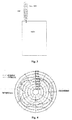
- Figure 1 is a schematic structure diagram of a dual-band antenna with a partial resonance structure according to the prior art
- Figure 2 is a schematic structure diagram of an exposed dual-band antenna with a GPS resonance part provided at a bottom of a helix according to the prior art
- Figure 3 is a schematic structure diagram of an exposed dual-band antenna with a GPS resonance part provided at a top of a helix according to the prior art
- Figure 4 is a gain pattern of a GPS frequency range of a dual pitch helical antenna according to the prior art
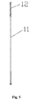
- FIG. 5 is a schematic structure diagram of a whip dual-band antenna according to the present invention.
- Figure 6 is frequency band specification of a simulation result of a UHF frequency range of a whip dual-band antenna according to the present invention
- Figure 7 is UHF radiation pattern specification of a simulation result of a UHF frequency range of a whip dual-band antenna according to the present invention.
- Figure 8 is frequency band parameters of a simulation result of a UHF frequency range of a whip dual-band antenna according to the present invention.
- Figure 9 is radiation pattern parameters of a simulation result of a UHF frequency range of a whip dual-band antenna according to the present invention.
- Figure 10 is frequency band specification of a fine tuning whip dual-band antenna sample according to the present invention.
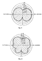
- Figure 11 is a gain radiation pattern of a whip antenna according to the present invention.
- Figure 12 is another gain radiation pattern of a whip antenna according to the present invention.
- FIG. 5 A structure of a whip dual-band antenna according to a preferable embodiment of the present invention is shown in Figure 5 , which includes a radiator connected to a radio via a feed point of the radio.
- the radiator includes two parts, the first part is a first radiator 11 with a linear shape for generating a first resonance, such as a whip antenna; and the second part is a second radiator 12 with a helical structure for generating a second resonance with a higher resonance frequency than the first radiator 11, such as a GPS resonance coil, where the second radiator 12 is provided on the top of the first radiator 11 in a series opposing.
- the first radiator 11 mainly generates the first resonance in the UHF frequency range (300-800MHz).
- the length of the second radiator 12 is a resonance length of the whip dual-band antenna operated in the GPS operating frequency range.
- the coil pitch may be adjusted by the coupling effect of the first radiator 11 and the second radiator 12, so as to tune the GPS resonance of different UHF frequency ranges.
- the current of the second radiator 12 is in the same direction as the upper current of the first radiator 11, such that the actual operating length of the second radiator 12 is equivalent to a length where two half-wave dipoles are superposed, and actually the length of the second resonance frequency model of the second radiator 12 is increased. Therefore, the influence of the variation of UHF frequency range on the second radiator is decreased, and the antenna has a good directivity on the upper hemisphere, which is better than the directivity in the case that one half-wave dipole is operated.
- the total length of the second radiator 12 is 1/4-1/2 of the resonance wavelength of the second radiator, and the total length of the first radiator 11 is 1/2 of the wavelength of the first resonance, and thus the UHF frequency range may not affect the GPS frequency range, such that the whip dual-band antenna has a better directivity, the dual-band tune is achieved in the whole frequency range (300-800MHz) of UHF, and the whip dual-band antenna can operate in more frequency ranges.
- Frequency band specification of a simulation result of UHF of a whip antenna according to the whip dual-band antenna of the present invention are shown in Figure 6
- UHF radiation pattern of a simulation result of UHF of the whip antenna are shown in Figure 7 .
- the simulation software is set to merely show the structure of the antenna and hide the part of the radio.
- the simulation result of Figure 6 and Figure 7 are idea values in the case that a sheath of an antenna and a radio shield are not used and the PCB loss is took no account.
- the gain radiation pattern of GPS is better.
- the GPS frequency range radiation pattern of the double pitch helical antenna shown in Figure 4 there is more energy toward sky, and there is no concave in the central or the gain which is weakened according to the direction, as shown in Figure 4 .
- the antenna performance of the dual-band antenna operated in the GPS frequency range is better concentrated on the upper hemisphere, which is better than the antenna performance of the double pitch helical antenna.
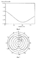
- a whip dual-band antenna sample according to the above design is tested in a chamber, and the range of the simulation frequency thereof is from 300MHZ to 2000MHZ, so as to obtain the frequency band parameter shown in Figure 10 and the gain direction shown in Figure 11 and Figure 12 .
- Reference numbers 1, 2, 3 in Figure 10 present the first resonance, the second resonance and the third resonance respectively.
- the third resonance of the whip dual-band antenna is not at 1575MHz but higher than 1575MHz, which can be adjusted by a variable pitch GPS resonance coil and will not affect the antenna GPS gain radiation pattern.
- the length of the second resonance frequency model is actually increased by providing the second radiator with a higher resonance frequency on the top of the first radiator, so as to decrease the influence of the second radiator on the UHF frequency range variation. Therefore, the antenna performance of the dual-band antenna operated in the GPS frequency range is better concentrated on the upper hemisphere, and a better GPS gain performance is achieved without affecting UHF frequency range effect.
Landscapes
- Engineering & Computer Science (AREA)
- Computer Networks & Wireless Communication (AREA)
- Physics & Mathematics (AREA)
- Electromagnetism (AREA)
- Variable-Direction Aerials And Aerial Arrays (AREA)
Abstract
Description
- The present invention relates to an antenna, and in particular to a whip dual-band antenna.
- In today's information society, people usually want to receive useful information conveniently, and thus various portable wireless communication devices are widely used in people's daily life. In a wireless communication device, an antenna used for transmitting and receiving radio waves to communicate radio signals is undoubtedly one of the very important elements. For most handheld terminal devices, the antenna needs to be light and small. In addition, the antenna is required to be operable for dual-band, and the frequency band of the antenna is required to be wider.
- At present,, a handheld terminal device is usually provided with several frequency ranges, such as frequency ranges required by Global System for Mobile Communications (GSM) and Digital Cellular System (DCS) of mobile telephones (GSM+DCS) as well as ultra high frequency (UHF) and a frequency of Global Positioning System (GPS) of interphone, to implement several functions or auxiliary functions. Therefore, the antennas of the handheld terminal device are a dual-band antenna or multi-band antenna.
- In the prior art, a dual-band antenna with a double branch structure is usually used in mobile telephone antenna design. The design idea is to lead out two radiation branch with different lengths from a feed point to generate resonances of different frequencies respectively.
- In the prior art, a dual-band antenna with a partial resonance structure is also usually used to design a higher frequency range with a different structure parameter. As shown in
Figure 1 , a kind of frequency is generated by the whole helix, while the high frequency resonance is generated by the helix part with the different parameter. For example, in the antennas of an early mobile telephone, the DCS frequency range is usually placed at the bottom of the coil to process. - An exposed dual-band antenna in existing art is usually implemented with the partial resonance structure with a helical structure, i.e., a double pitch helical antenna. In this structure, the high frequency resonance part is placed at the bottom of the coil, which is combined with the other part to constitute a low frequency resonance. However, an exposed dual-band antenna of an interphone is operated in an operating mode of UHF+GPS frequency range. As shown in
Figure 2 , the GPS resonance part is placed at the bottom of the helix to form the resonance in the prior art, by which the performance of the antenna is mostly concentrated on the lower hemisphere, and the performance on the upper hemisphere required by GPS (a part directing to the sky) is poor and is not suitable for a specialized GPS performance and a function positioning of the professional terminal device. Moreover, in this design, the bandwidth of the UHF frequency range is narrow due to the influence of the GPS frequency range. - In order to solve problems of the performance of GPS frequency range of antenna, in the existing UHF+GPS exposed dual-band antenna, the GPS resonance part is placed at the top of the antenna coil, as shown in
Figure 3 , so as to obtain a GPS receiving performance concentrated upwardly. The GPS performance will reach a relatively poor state when UHF frequency is about certain integral multiple of GPS frequency, which is determined by a special frequency range relationship and is unavoidable. For this antenna, UHF is operated in the first resonance mode, i.e., the total length of the coil is about half of the resonance wavelength, and the length of the top GPS is also about half of the wavelength, and therefore the GPS performance is greatly affected by the UHF frequency range. - Technical problems to be solved by the present invention are that: for the above disadvantages in the prior art, a whip dual-band antenna is provided, so that the antenna performance is better concentrated on the upper hemisphere when the dual-band antenna is operated in the GPS frequency range, and GPS performance is achieved better without affecting the UHF performance.
- Technical solutions for solving the technical problems in the present invention are: constructing a whip dual-band antenna including a radiator connected to a radio via a feed point of the radio, wherein the radiator includes a first radiator with a linear shape for generating a first resonance; and a second radiator with a helical structure for generating a second resonance with a higher resonance frequency than the first radiator, which is provided at the top of the first radiator in a series opposing.
- For the whip dual-band antenna of the present invention, a total length of the second radiator is 1/4-1/2 of a wavelength of the second resonance.
- For the whip dual-band antenna of the present invention, the current of the second radiator is in the same direction as a current at the top of the first radiator, and an operating length of the second radiator is a length where two half-wave dipoles are superposed.
- For the whip dual-band antenna of the present invention, a total length of the first radiator is 1/2 of the wavelength of the first resonance.
- For the whip dual-band antenna of the present invention, the first radiator uses a whip antenna.
- For the whip dual-band antenna of the present invention, the second radiator uses a GPS resonance coil.
- The whip dual-band antenna of the present invention has the following advantages: the second radiator with a higher resonance frequency is provided on the top of the first radiator, the length of the second resonance frequency model is increased, and thus influence of the UHF frequency range variation is decreased, the antenna performance of the dual-band antenna operated in the GPS frequency range is better concentrated on the upper hemisphere, and a better GPS gain performance is achieved without affecting the UHF effect.
- The present invention will be further explained below in conjunction with drawings and embodiments. In drawings,
-
Figure 1 is a schematic structure diagram of a dual-band antenna with a partial resonance structure according to the prior art; -
Figure 2 is a schematic structure diagram of an exposed dual-band antenna with a GPS resonance part provided at a bottom of a helix according to the prior art; -
Figure 3 is a schematic structure diagram of an exposed dual-band antenna with a GPS resonance part provided at a top of a helix according to the prior art; -
Figure 4 is a gain pattern of a GPS frequency range of a dual pitch helical antenna according to the prior art; -
Figure 5 is a schematic structure diagram of a whip dual-band antenna according to the present invention; -
Figure 6 is frequency band specification of a simulation result of a UHF frequency range of a whip dual-band antenna according to the present invention; -
Figure 7 is UHF radiation pattern specification of a simulation result of a UHF frequency range of a whip dual-band antenna according to the present invention; -
Figure 8 is frequency band parameters of a simulation result of a UHF frequency range of a whip dual-band antenna according to the present invention; -
Figure 9 is radiation pattern parameters of a simulation result of a UHF frequency range of a whip dual-band antenna according to the present invention; -
Figure 10 is frequency band specification of a fine tuning whip dual-band antenna sample according to the present invention; -
Figure 11 is a gain radiation pattern of a whip antenna according to the present invention; and -
Figure 12 is another gain radiation pattern of a whip antenna according to the present invention. - Preferable embodiments of the present invention will be described in detail below in conjunction with the drawings.
- A structure of a whip dual-band antenna according to a preferable embodiment of the present invention is shown in
Figure 5 , which includes a radiator connected to a radio via a feed point of the radio. The radiator includes two parts, the first part is afirst radiator 11 with a linear shape for generating a first resonance, such as a whip antenna; and the second part is asecond radiator 12 with a helical structure for generating a second resonance with a higher resonance frequency than thefirst radiator 11, such as a GPS resonance coil, where thesecond radiator 12 is provided on the top of thefirst radiator 11 in a series opposing. Thefirst radiator 11 mainly generates the first resonance in the UHF frequency range (300-800MHz). The length of thesecond radiator 12 is a resonance length of the whip dual-band antenna operated in the GPS operating frequency range. The coil pitch may be adjusted by the coupling effect of thefirst radiator 11 and thesecond radiator 12, so as to tune the GPS resonance of different UHF frequency ranges. - By providing the
second radiator 12 on the top of thefirst radiator 11 in a series opposing, the current of thesecond radiator 12 is in the same direction as the upper current of thefirst radiator 11, such that the actual operating length of thesecond radiator 12 is equivalent to a length where two half-wave dipoles are superposed, and actually the length of the second resonance frequency model of thesecond radiator 12 is increased. Therefore, the influence of the variation of UHF frequency range on the second radiator is decreased, and the antenna has a good directivity on the upper hemisphere, which is better than the directivity in the case that one half-wave dipole is operated. - Preferably, the total length of the
second radiator 12 is 1/4-1/2 of the resonance wavelength of the second radiator, and the total length of thefirst radiator 11 is 1/2 of the wavelength of the first resonance, and thus the UHF frequency range may not affect the GPS frequency range, such that the whip dual-band antenna has a better directivity, the dual-band tune is achieved in the whole frequency range (300-800MHz) of UHF, and the whip dual-band antenna can operate in more frequency ranges. - Frequency band specification of a simulation result of UHF of a whip antenna according to the whip dual-band antenna of the present invention are shown in
Figure 6 , UHF radiation pattern of a simulation result of UHF of the whip antenna are shown inFigure 7 . For clarify, the simulation software is set to merely show the structure of the antenna and hide the part of the radio. The simulation result ofFigure 6 and Figure 7 are idea values in the case that a sheath of an antenna and a radio shield are not used and the PCB loss is took no account. - In the present embodiment, taking UHF (470-520MHz) +GPS as a simulation model, frequency band parameters of the simulation data of the UHF frequency range of the whip dual-band antenna are shown in
Figure 8 , radiation pattern parameters of the simulation result of the UHF frequency range are shown inFigure 9 . The simulation gain data inFigure 8 andFigure 9 are idea values in the case that a sheath of an antenna and a radio shield are not used and the PCB loss is took no account. - As can be seen from
Figure 8 andFigure 9 , in the case that the second radiator (a GPS resonance coil) is provided on the top of the first radiator (a whip antenna), the gain radiation pattern of GPS is better. Compared with the GPS frequency range radiation pattern of the double pitch helical antenna shown inFigure 4 , there is more energy toward sky, and there is no concave in the central or the gain which is weakened according to the direction, as shown inFigure 4 . The antenna performance of the dual-band antenna operated in the GPS frequency range is better concentrated on the upper hemisphere, which is better than the antenna performance of the double pitch helical antenna. Moreover, it can be seen from the radiation pattern of the GPS frequency range and the simulation result of the UHF frequency range inFigure 6 and Figure 7 that the performance of the UHF frequency range is almost unaffected and dual-band turn can be achieved well in the whole frequency range (300-800MHz) of UHF. - A whip dual-band antenna sample according to the above design is tested in a chamber, and the range of the simulation frequency thereof is from 300MHZ to 2000MHZ, so as to obtain the frequency band parameter shown in
Figure 10 and the gain direction shown inFigure 11 and Figure 12 .Reference numbers Figure 10 present the first resonance, the second resonance and the third resonance respectively. As can be seen, the third resonance of the whip dual-band antenna is not at 1575MHz but higher than 1575MHz, which can be adjusted by a variable pitch GPS resonance coil and will not affect the antenna GPS gain radiation pattern. - According to the whip dual-band antenna of the present invention, the length of the second resonance frequency model is actually increased by providing the second radiator with a higher resonance frequency on the top of the first radiator, so as to decrease the influence of the second radiator on the UHF frequency range variation. Therefore, the antenna performance of the dual-band antenna operated in the GPS frequency range is better concentrated on the upper hemisphere, and a better GPS gain performance is achieved without affecting UHF frequency range effect.
- The above is merely preferable embodiments of the present invention, and does not intent to limit the present invention, and any amendments, equivalent substitutions or improvements within spirit and principle of the present invention are all included in the protection scope of the present invention.
Claims (6)
- A whip dual-band antenna, comprising a radiator connected to a radio via a feed point of the radio, wherein the radiator comprises a first radiator with a linear shape for generating a first resonance; and a second radiator with a helical structure for generating a second resonance with a higher resonance frequency than the first radiator, which is provided at the top of the first radiator in a series opposing.
- The whip dual-band antenna according to claim 1, wherein a total length of the second radiator is 1/4-1/2 of a wavelength of the second resonance.
- The whip dual-band antenna according to claim 1, wherein the current of the second radiator is in the same direction as a current at the top of the first radiator, and an operating model of the second radiator is operated in the mode that two half-wave dipoles are superposed.
- The whip dual-band antenna according to claim 1, wherein a length of the first radiator is 1/2 of a wavelength of the first resonance.
- The whip dual-band antenna according to claim 1, wherein the first radiator uses a whip antenna.
- The whip dual-band antenna according to claim 1, wherein the second radiator uses a GPS resonance coil.
Applications Claiming Priority (1)
| Application Number | Priority Date | Filing Date | Title |
|---|---|---|---|
| PCT/CN2010/071272 WO2011116522A1 (en) | 2010-03-24 | 2010-03-24 | Whip dual-band antenna |
Publications (2)
| Publication Number | Publication Date |
|---|---|
| EP2551957A1 true EP2551957A1 (en) | 2013-01-30 |
| EP2551957A4 EP2551957A4 (en) | 2014-04-02 |
Family
ID=44672445
Family Applications (1)
| Application Number | Title | Priority Date | Filing Date |
|---|---|---|---|
| EP10848184.7A Withdrawn EP2551957A4 (en) | 2010-03-24 | 2010-03-24 | ANTENNA WHIP BIBANDE |
Country Status (3)
| Country | Link |
|---|---|
| US (1) | US20130009840A1 (en) |
| EP (1) | EP2551957A4 (en) |
| WO (1) | WO2011116522A1 (en) |
Families Citing this family (1)
| Publication number | Priority date | Publication date | Assignee | Title |
|---|---|---|---|---|
| US8897407B2 (en) | 2011-12-04 | 2014-11-25 | Hemisphere Gnss Inc. | RF (including GNSS) signal interference mitigation system and method |
Family Cites Families (12)
| Publication number | Priority date | Publication date | Assignee | Title |
|---|---|---|---|---|
| US5734352A (en) * | 1992-08-07 | 1998-03-31 | R. A. Miller Industries, Inc. | Multiband antenna system |
| JPS63286008A (en) * | 1987-05-19 | 1988-11-22 | Toyo Commun Equip Co Ltd | Two-frequency common use antenna |
| SE509638C2 (en) * | 1996-06-15 | 1999-02-15 | Allgon Ab | Meander antenna device |
| US7848788B2 (en) * | 1999-04-15 | 2010-12-07 | The Johns Hopkins University | Magnetic resonance imaging probe |
| WO2001028033A1 (en) * | 1999-10-12 | 2001-04-19 | Galtronics Ltd. | Portable antenna |
| JP2002176310A (en) * | 2000-12-06 | 2002-06-21 | Nippon Antenna Co Ltd | 2 resonance antenna |
| US6452555B1 (en) * | 2001-01-24 | 2002-09-17 | Auden Techno Corp. | Multi-frequency helix antenna |
| US7592958B2 (en) * | 2003-10-22 | 2009-09-22 | Sony Ericsson Mobile Communications, Ab | Multi-band antennas and radio apparatus incorporating the same |
| CN2789949Y (en) * | 2005-04-26 | 2006-06-21 | 佛山市顺德区汉达精密电子科技有限公司 | Double-frequency antenna |
| CN1937317A (en) * | 2005-09-21 | 2007-03-28 | 英华达(上海)电子有限公司 | Multi-mode and multi frequency band combined antenna |
| US7817103B2 (en) * | 2008-02-28 | 2010-10-19 | Motorola, Inc. | Dual-band multi-pitch parasitic half-wave (MPPH) antenna |
| CA2724370C (en) * | 2009-12-08 | 2018-05-29 | Shahrzad Jalali Mazlouman | Reconfigurable axial-mode helical antenna |
-
2010
- 2010-03-24 US US13/636,641 patent/US20130009840A1/en not_active Abandoned
- 2010-03-24 WO PCT/CN2010/071272 patent/WO2011116522A1/en not_active Ceased
- 2010-03-24 EP EP10848184.7A patent/EP2551957A4/en not_active Withdrawn
Also Published As
| Publication number | Publication date |
|---|---|
| WO2011116522A1 (en) | 2011-09-29 |
| EP2551957A4 (en) | 2014-04-02 |
| US20130009840A1 (en) | 2013-01-10 |
Similar Documents
| Publication | Publication Date | Title |
|---|---|---|
| CN103236583B (en) | A kind of novel LTE metal frame antenna strengthening bandwidth | |
| Abedin et al. | Modifying the ground plane and its effect on planar inverted-F antennas (PIFAs) for mobile phone handsets | |
| US20110306310A1 (en) | Multi-antenna wireless transceiving device | |
| Huang et al. | Eight-band antenna for full-screen metal frame LTE mobile phones | |
| Rao et al. | Shared-aperture design of the cellular antenna and satellite communication antenna with circular polarization in S-band for metal-bezel smartphones | |
| CN102800967A (en) | Antenna for a portable computer | |
| Ban et al. | Small-size wideband monopole with distributed inductive strip for seven-band WWAN/LTE mobile phone | |
| US9825352B2 (en) | Wireless electronic devices including a feed structure connected to a plurality of antennas | |
| CN101356689A (en) | Multiband antenna device for radio communication terminal having wide high frequency band bandwidth | |
| Puri et al. | A review of antennas for wireless communication devices | |
| Chen et al. | Planar monopole antenna with a parasitic shorted strip for multistandard handheld terminals | |
| US8816935B2 (en) | Dual frequency antenna with wide frequency | |
| Ghnimi et al. | Study of a new Design of the planar inverted-F Antenna for Mobile phone handset Applications | |
| EP1396044A1 (en) | Antenna arrangement | |
| CN101958457B (en) | Wideband dual-frequency antenna | |
| Murali Krishna et al. | Bandwidth enhancement of circular ring fractal antenna for wireless applications | |
| Yang et al. | A novel U-shaped planar microstrip antenna for dual-frequency mobile telephone communications | |
| WO2012006781A1 (en) | Dual frequency antenna | |
| Ma et al. | Miniature printed octaband monopole antenna for mobile phones | |
| EP2551957A1 (en) | Whip dual-band antenna | |
| Jeong et al. | Dual-band Wi-Fi antenna with a ground stub for bandwidth enhancement | |
| CN201838714U (en) | Enclosed type multi-band antenna and wireless communication device of same | |
| CN201829614U (en) | Whip dual-frequency antenna | |
| Deng et al. | A novel design of LTE smart mobile antenna with multiband operation | |
| Li et al. | A compact monopole antenna for smartphones |
Legal Events
| Date | Code | Title | Description |
|---|---|---|---|
| PUAI | Public reference made under article 153(3) epc to a published international application that has entered the european phase |
Free format text: ORIGINAL CODE: 0009012 |
|
| 17P | Request for examination filed |
Effective date: 20120926 |
|
| AK | Designated contracting states |
Kind code of ref document: A1 Designated state(s): AT BE BG CH CY CZ DE DK EE ES FI FR GB GR HR HU IE IS IT LI LT LU LV MC MK MT NL NO PL PT RO SE SI SK SM TR |
|
| DAX | Request for extension of the european patent (deleted) | ||
| A4 | Supplementary search report drawn up and despatched |
Effective date: 20140303 |
|
| RIC1 | Information provided on ipc code assigned before grant |
Ipc: H01Q 9/30 20060101ALI20140225BHEP Ipc: H01Q 5/00 20060101ALI20140225BHEP Ipc: H01Q 1/36 20060101AFI20140225BHEP |
|
| STAA | Information on the status of an ep patent application or granted ep patent |
Free format text: STATUS: EXAMINATION IS IN PROGRESS |
|
| 17Q | First examination report despatched |
Effective date: 20161219 |
|
| STAA | Information on the status of an ep patent application or granted ep patent |
Free format text: STATUS: THE APPLICATION IS DEEMED TO BE WITHDRAWN |
|
| 18D | Application deemed to be withdrawn |
Effective date: 20170503 |